EP3546722A1 - Pleuel für eine brennkraftmaschine mit variabler verdichtung - Google Patents
Pleuel für eine brennkraftmaschine mit variabler verdichtung Download PDFInfo
- Publication number
- EP3546722A1 EP3546722A1 EP19163702.4A EP19163702A EP3546722A1 EP 3546722 A1 EP3546722 A1 EP 3546722A1 EP 19163702 A EP19163702 A EP 19163702A EP 3546722 A1 EP3546722 A1 EP 3546722A1
- Authority
- EP
- European Patent Office
- Prior art keywords
- connecting rod
- valve housing
- valve
- axial
- securing
- Prior art date
- Legal status (The legal status is an assumption and is not a legal conclusion. Google has not performed a legal analysis and makes no representation as to the accuracy of the status listed.)
- Granted
Links
Images


Classifications
-
- F—MECHANICAL ENGINEERING; LIGHTING; HEATING; WEAPONS; BLASTING
- F02—COMBUSTION ENGINES; HOT-GAS OR COMBUSTION-PRODUCT ENGINE PLANTS
- F02B—INTERNAL-COMBUSTION PISTON ENGINES; COMBUSTION ENGINES IN GENERAL
- F02B75/00—Other engines
- F02B75/04—Engines with variable distances between pistons at top dead-centre positions and cylinder heads
- F02B75/045—Engines with variable distances between pistons at top dead-centre positions and cylinder heads by means of a variable connecting rod length
Definitions
- the invention relates to a connecting rod for a variable compression internal combustion engine, and to a variable compression internal combustion engine having a connecting rod.
- a high compression ratio has a positive effect on the efficiency of the internal combustion engine.
- compression ratio is generally understood the ratio of the entire cylinder space before compression to the remaining cylinder space after compression.
- the compression ratio may only be selected so high that a so-called "knocking" of the internal combustion engine is avoided during full load operation.
- the compression ratio could be selected with higher values without "knocking" occurring.
- the important part load range of an internal combustion engine can be improved if the compression ratio is variably adjustable.
- systems with variable connecting rod length for example, are known, which actuate an adjusting device of a connecting rod with the aid of hydraulic changeover valves.
- a generic switching valve is for example from the DE 10 2012 112 461 A1 refer to.
- the switching valve is designed as a cartridge solution. This has the advantage that the changeover valve can be checked for leaks independently of the connecting rod arrangement in which the changeover valve is installed. The changeover valve is pressed into the connecting rod body.
- An object of the invention is to provide an improved, and inexpensive connecting rod for a variable compression internal combustion engine, which is process reliable to manufacture.
- Another object is to provide an internal combustion engine with variable compression with such a connecting rod.
- a connecting rod for an internal combustion engine with variable compression with an adjusting device for adjusting an effective connecting rod length, wherein an adjustment of the adjusting device by means of a switching valve is adjustable.
- a valve housing of the changeover valve is axially secured in a bore of the connecting rod.
- the connecting rod comprises a Pleuel Sciences and a connecting rod cover arranged thereon, which enclose a Bublagerauge.
- a connecting rod bearing eye can be arranged with the eccentric adjusting device.
- As a connecting rod length the distance of a central axis of the Hublagerauges is defined to a central axis of the connecting rod bearing eye.
- a press fit can be interpreted only with such a degree of excess as the structural mechanics of the connecting rod and the valve due to mounting voltages allowed.
- the valves can rotate axially with weak press dressings and low friction.
- the orientation of the switching valve in the bore can be of crucial importance for the operation of the valve, for example, if the tap of the valve is not arranged in the valve axis. This results in a conflict of objectives for the press dressing design: sufficient axial holding force, position fixation and low leakage against impermissibly high mounting voltage superimposed by operating voltages.
- the valve housing of the changeover valve is axially secured in the bore of the connecting rod.
- the valve housing can not loosen and move or rotate out of its intended position in the connecting rod body.
- the upper limit of the press fit valve housing in the connecting rod body can be adapted to the maximum allowable mounting voltages and the lower limit shifted to an economical production.
- the risk of axial displacement or rotation of the reversing valve in the connecting rod during engine operation can be advantageously reduced by means of the end-side axial securing of the valve housing in the connecting rod described here.
- a simple axial securing can take place via a weld or weld points between the valve housing and connecting rod body or connecting rod cover.
- an adhesive or an end coating, such as paint can be used as a backup.
- the connecting rod may have one or more axial counterbores whose protrusions for axial securing of the changeover valve are formed in one or more end-side recesses of the valve housing.
- This variant uses a countersink hole in the connecting rod and frontal cut-outs in the valve.
- the countersink holes serve as a centering for a forming tool, for example, with a hard ball head, which presses the projection of the countersink hole in the cutout of the valve, so as to securely fix the valve axially and against rotation.
- a countersink can be assigned to several cutouts of different valves.
- the axial lock can be selected independently of the valve position in the connecting rod. Likewise, several milled or reshaping operations can be applied.
- Countersink bores which are arranged in the connecting rod sufficiently close to the bore in the connecting rod for receiving the changeover valve, can be sufficiently thin Have wall thickness to the bore as a supernatant out, so that the material of these supernatants can be displaced by mechanical pressure to the bore. If the valve housing has end-side recesses at this point, then the material of the projections can be pushed into these recesses. As a result, a toothing between Pleuel stresses or Pleueldeckel and valve housing takes place. The valve housing is secured in this way in the bore against axial displacements. If the recesses in the valve housing are not circumferential but are arranged over a limited angular range, then the valve housing and thus the changeover valve can also be secured against rotation in the bore.
- the valve housing may have axial countersink holes, the supernatants for axial securing of the changeover valve are formed into one or more end-side recesses of the connecting rod.
- the counterbores can also be arranged in the valve and the frontal cut-outs in the connecting rod body.
- the projections of the counterbores can be pressed by means of a forming tool in the recesses.
- the material of the supernatants can be pressed into the recesses by exerting a mechanical pressure, as can be generated, for example, by means of a forming tool.
- the connecting rod balls can be pressed into the countersink holes, whereby the supernatants are pressed into the recesses.
- a variant of this technical solution is the injection of a ball in the countersink hole. The supernatant is so far deformed when pressing the ball in the countersink hole that an axial and Anti-rotation occurs, but also the ball is prevented from loosening.
- the desired toothing between Pleuel stresses or connecting rod cover and valve housing can be achieved in a suitable manner.
- conical or frusto-conical bodies could be pressed into the counterbores to achieve the desired effect.
- the recesses may be provided as on a peripheral edge of the valve housing chamfer.
- a simple embodiment of the recesses of the valve housing can be achieved in the form of a peripheral on the outer edge of the valve housing chamfer. This makes it possible to achieve axial securing of the reversing valve in the bore of the connecting rod. If the material of the supernatants with a suitable pressure in the chamfer and pressed against the valve housing, then it can also be used to secure against rotation of the valve housing in the bore.
- the valve housing may have on at least one end face an axial projection, wherein for the axial securing of the changeover valve, the supernatant is fixed with a retaining ring.
- Another variant of the frontal axial securing is in projecting valves, which are fixed by means of retaining rings in their axial position. DIN standard parts can also be used as circlips.
- the retaining ring can be fixed to the valve via a fit, a weld, in a groove, a thread or a similar fixation possibility.
- the valve housing may have on a first end face an axial shoulder and on a second end face an axial projection, wherein for the axial securing of the changeover valve, the supernatant is fixed with a retaining ring.
- the valve may alternatively be provided with an axial shoulder on an end face, which comes to rest on the connecting rod or connecting rod cover and a locking ring on the axial projection of the second end face, as a counterhold on the other end face of the connecting rod for fixing the valve housing serves.
- the circlip can be fixed to the valve via a fit, a weld, in a groove, a thread, or similar fixation capability.
- the connecting rod of the circlip may be mounted on the supernatant by means of a press fit, a weld or a thread.
- the securing ring can expediently be fixed to the valve via a fit, a weld, in a groove, a thread or a similar fixation possibility.
- the connecting rod of the locking ring may have at least one rotation.
- an additional anti-rotation of the locking ring can be secured against rotation, for example, as a ring with retaining tabs, which engage in a counterpart or both sides, executed.
- the anti-rotation may comprise at least one of the locking ring radially outwardly standing tab, which is fixed to the connecting rod, in particular to the connecting rod cover.
- the tab can be materially connected to the connecting rod, for example, be welded.
- the tab can engage in a recess of the connecting rod.
- the tab can engage in a recess of the connecting rod.
- the valve housing may have on at least one end face an axial projection, wherein for the axial securing of the changeover valve, the supernatant is provided reshaped after the assembly of the valve housing.
- the valve housing is in the area the supernatant heat treated before the forming process.
- the connecting rod can be mounted on at least one end face of the valve housing at least one grain for axially securing the switching valve, whereby material of the valve housing is displaced in a bore gap between the valve housing and connecting rod.
- material deformation By material deformation, the changeover valve can be secured against axial movement and against rotation. This can be achieved on the one hand by graining the end face of the valve housing, in which material is deformed radially outward in the direction of the connecting rod or connecting rod cover.
- the connecting rod can be mounted on at least one end face of the connecting rod at least one grain for axial securing of the changeover valve, whereby material of the connecting rod is displaced in the bore gap between the valve housing and connecting rod.
- the axial securing of the switching valve can also be achieved by graining the end face of the connecting rod, in which material is deformed radially inward in the direction of the valve housing.
- At least one securing element for axial securing of the changeover valve can be arranged in the bore gap between valve housing and connecting rod.
- a securing element such as a key, a cone, a wedge, which may also be designed as a DIN standard part, and which is driven frontally between the valve and bore in the bore gap.
- This can additionally be welded, glued or fixed in a similar manner.
- a combination of using a retaining ring and the axial securing with securing element represents the axial securing means of locking pins.
- at least one pin in the bore gap or a pocket between the connecting rod body and valve housing can be pressed, welded, glued or otherwise joined.
- an internal combustion engine with at least one connecting rod is proposed.
- a connecting rod can be used as described above in order to realize an adjustment device in a favorable manner and to implement an advantageous combustion process and thus fuel consumption in the internal combustion engine.
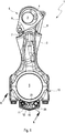
- FIGS. 1 and 2 show a connecting rod 1 according to the invention for a variable compression of an internal combustion engine, wherein FIG. 1 a side view of the connecting rod 1 and FIG. 2 an enlarged section through the connecting rod cover 10 shows.
- the connecting rod 1 has a Pleuel Sciences 2 and at least partially arranged in a connecting rod bearing eye 3 adjustable eccentric adjustment 6 with an eccentric 4.
- At the opposite end of the connecting rod 2 is a Hublagerauge 5 arranged, which is closed with the connecting rod cover 10.
- the eccentric adjusting device 6 is used to adjust an effective connecting rod length.
- As a connecting rod length the distance of a central axis of the Hublagerauges 5 is defined to a central axis of the connecting rod bearing eye 3.
- other types of adjusting devices for adjusting an effective connecting rod length in the context of the invention are conceivable, so that the invention is not limited to this specific embodiment.
- a rotation of the adjustable eccentric adjusting device 6 is initiated by the action of mass and load forces of the internal combustion engine, which act on the eccentric adjusting device 6 at a power stroke of the internal combustion engine.
- the rotational movement or adjustment is supported by hydraulic fluid, in particular engine oil, acted upon, integrated in the connecting rod 1 piston. The pistons thereby prevent a return of the eccentric adjusting device 6 due to varying force action directions of the force acting on the eccentric adjusting device 6 forces.
- the pistons are operatively connected by means of eccentric rods 7, 8 on both sides with a lever 9 of the eccentric device 6.
- the pistons are arranged displaceably in hydraulic chambers and are acted upon by hydraulic fluid, not shown, with hydraulic fluid via non-visible check valves. These prevent a backflow of hydraulic fluid from the hydraulic chambers back into the hydraulic fluid lines and allow a Nachsaugen hydraulic fluid in the hydraulic chambers.
- the hydraulic fluid conduits connected to the hydraulic chambers all or at least partially interact with a switching valve 11.
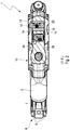
- the switching valve 11 which in FIG. 2 is shown in an enlarged section in the sectional plane EE, has a arranged in a valve housing 12 tap element 13, which in an axial direction displaceable either in a first switching position or a second switching position displaceable and can be locked by means of a spring-loaded locking element optionally in the first or the second switching position.
- a press fit can be interpreted only with such a large excess, as permitted by the structural mechanics of the connecting rod 1 and the changeover valve 11 due to mounting voltages.
- the changeover valves 11 can twist axially with weak press dressings and too little friction.
- the orientation of the changeover valve 11 in the bore 23 may be important if, for example, the tappet is introduced outside an axis in the changeover valve. This results in a conflict of objectives for the press dressing design, namely sufficient axial holding force, position fixation and low leakage against an inadmissibly high mounting voltage superimposed by operating voltages.
- valve housing 12 of the changeover valve 11 is provided axially secured in a bore 23 of the connecting rod 1.
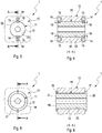
- the connecting rod 1, or the connecting rod cover 10 As in particular in the plan view in FIG. 3 and in the corresponding section in FIG. 4 can be seen, the connecting rod 1, or the connecting rod cover 10, according to one embodiment, one or more axial counterbores 14, whose directed to the valve housing 12 projections 15 for axial securing of the changeover valve 11 into one or more end-side recesses 16 of the valve housing 12 formed become.
- the axial counterbores 14 in the valve housing 12 and the recesses 16 in the connecting rod it is also possible to provide the axial counterbores 14 in the valve housing 12 and the recesses 16 in the connecting rod.
- the projections 15 of the counterbores 14 are pressed by means of a forming tool into the recesses 16.
- the counterbores 14 serve as centering for the forming tool, for example for a hard ball head, which deforms the supernatants 15 and presses into the recesses 16, so that the valve housing 12 is axially secured in the bore of the connecting rod 1 and secured against rotation.
- An embodiment, not shown, provides that in the countersink holes 14 of the connecting rod 1 balls are pressed, whereby the supernatants 15 are pressed into the recesses 16.
- the recesses 16 may be provided as on an outer edge 30 of the valve housing 12 circumferential chamfer. Also, it can be achieved in the connecting rod 1 with sufficient solid contact pressure of the projections 15 of the counterbores 14 an axial securing as well as a rotation of the valve housing.
- the switching valve 11 may have on a first end face 20 an axial stop in the form of a shoulder 17, which at the connecting rod 1 and in the in the FIGS. 5 and 6 embodiment shown comes to the connecting rod cover 10 to the plant.
- the valve housing 12 On a second End 21, the valve housing 12 has an axial projection 18, wherein for the axial securing of the changeover valve 11, the supernatant 18 is fixed with a retaining ring 19.
- the locking ring 19 can for example be pressed onto the projection 18, welded or fastened by means of a thread. Other mounting options are also conceivable within the scope of the invention. According to an embodiment not shown, the locking ring 19 can engage in a groove of the valve housing 12 and be fixed therein.
- valve housing 12 may be formed without the paragraph 17. If the securing ring 19 arranged on the projection 18 is firmly fixed, for example welded, to both the valve housing 12 and the connecting rod body 2 or connecting rod cover 10, an axial securing as well as an anti-rotation lock of the valve housing 12 in the connecting rod 1 can also be achieved via this.
- the supernatant 18 of the valve housing 12 can be converted to the axial securing of the changeover valve 11.
- the valve housing 12 is heat treated after assembly in the connecting rod 1 in the region of the supernatant 18 to perform the forming process of the supernatant 18 at the second end face 21 can.
- the heat treatment is carried out, for example, by tempering the material, for example by means of a laser process or an inductive heating.
- a penetration depth of the heat treatment can advantageously be chosen so that only the supernatant 18 is heat treated.
- the reshaping of the supernatant 18 is carried out by way of example by a crimping process.
- the locking ring 19 can, as in the isometric view in FIG. 7 shown, additionally have a rotation 26. Conceivable, for example, retaining tabs 25 which engage in corresponding recesses in the connecting rod 1.
- the anti-rotation device 26 may at least one of the retaining ring 19 radially comprise outwardly standing tab 25 which is fixed to the connecting rod 1, in particular to the connecting rod cover 10.
- the embodiment in FIG. 7 has two mutually opposite radially outward tabs 25.
- the tabs 25 can engage in corresponding recesses of the connecting rod 1 and so represent an effective anti-rotation 26.
- FIG. 8 shows a schematic plan view of a in the connecting rod 1 after FIG. 1 built-in switching valve 11 with grain 22 on an end face 20, 21 of the valve housing 12 according to a further embodiment of the invention.
- material of the valve housing 12 is displaced into a bore gap 27 between the valve housing 12 and the connecting rod 1 for axially securing the reversing valve 11 by means of a forming tool.
- the arrow directions 24 in FIG. 8 The material is displaced away from the grain 22 radially outward into the bore gap 27, whereby the valve housing 12 is effectively fixed in the bore gap 27 of the connecting rod cover 10 and thus both axially secured and secured against rotation.
- the end faces 20, 21 of the valve housing 12 close with the end faces 28, 29 of the connecting rod cover 10 from.
- FIG. 9 is shown as an alternative embodiment, a switching valve 11 with grain 22 in the connecting rod cover 10.
- the material of the connecting rod cover 10 for axial securing of the changeover valve 11 is displaced radially inwardly into the bore gap 27 in accordance with the illustrated deformation direction 24.
- a simple axial securing can also take place via a weld or weld points.
- an adhesive or an end coating can be used as a safeguard against falling out or twisting of the valve housing 12 in the connecting rod 1.
- a securing element 31 for example a feather key, a cone, or a wedge, which can be designed, for example, as a DIN standard part, and which is driven at the end between valve housing 12 and bore.
- a securing element 31 for example a feather key, a cone, or a wedge, which can be designed, for example, as a DIN standard part, and which is driven at the end between valve housing 12 and bore.
- This can additionally be welded, glued or joined in a similar way.
- FIG. 10 shows in a schematic plan view into the connecting rod 1 FIG. 1 built-in switching valve 11 with such fuse elements 31 according to a further embodiment of the invention.
- at least one, in FIG. 10 arranged three securing elements 31 for axial securing of the changeover valve 11 in the bore gap 27 between the valve housing 12 and connecting rod 1.
- a combination of using a retaining ring 19 and the axial securing means securing element 31 represents the axial securing means of pins.
- at least one pin is pressed into a pocket in Pleuel Sciences or connecting rod cover and the valve housing 12 per side, welded, glued or otherwise joined.
Landscapes
- Engineering & Computer Science (AREA)
- Chemical & Material Sciences (AREA)
- Combustion & Propulsion (AREA)
- Mechanical Engineering (AREA)
- General Engineering & Computer Science (AREA)
- Shafts, Cranks, Connecting Bars, And Related Bearings (AREA)
Abstract
Description
- Die Erfindung betrifft einen Pleuel für eine Brennkraftmaschine mit variabler Verdichtung, sowie eine Brennkraftmaschine mit variabler Verdichtung mit einem Pleuel.
- Bei Brennkraftmaschinen wirkt sich ein hohes Verdichtungsverhältnis positiv auf den Wirkungsgrad der Brennkraftmaschine aus. Unter Verdichtungsverhältnis wird im Allgemeinen das Verhältnis des gesamten Zylinderraumes vor der Verdichtung zum verbliebenen Zylinderraum nach der Verdichtung verstanden. Bei Brennkraftmaschinen mit Fremdzündung, insbesondere Ottomotoren, die ein festes Verdichtungsverhältnis aufweisen, darf das Verdichtungsverhältnis jedoch nur so hoch gewählt werden, dass bei Volllastbetrieb ein sogenanntes "Klopfen" der Brennkraftmaschine vermieden wird. Jedoch könnte für den weitaus häufiger auftretenden Teillastbereich der Brennkraftmaschine, also bei geringer Zylinderfüllung, das Verdichtungsverhältnis mit höheren Werten gewählt werden, ohne dass ein "Klopfen" auftreten würde. Der wichtige Teillastbereich einer Brennkraftmaschine kann verbessert werden, wenn das Verdichtungsverhältnis variabel einstellbar ist. Zur Verstellung des Verdichtungsverhältnisses sind beispielsweise Systeme mit variabler Pleuelstangenlänge bekannt, welche mit Hilfe von hydraulischen Umschaltventilen eine Verstelleinrichtung eines Pleuels betätigen.
- Ein gattungsgemäßes Umschaltventil ist beispielsweise aus der
DE 10 2012 112 461 A1 zu entnehmen. Das Umschaltventil ist als Patronenlösung ausgeführt. Dies weist den Vorteil auf, dass das Umschaltventil unabhängig von der Pleuelstangenanordnung, in welches das Umschaltventil verbaut wird, auf Dichtigkeit geprüft werden kann. Das Umschaltventil ist in den Pleuelkörper eingepresst. - Eine Aufgabe der Erfindung ist es, einen verbesserten, und kostengünstigen Pleuel für eine Brennkraftmaschine mit variabler Verdichtung zu schaffen, welches prozesssicher herzustellen ist.
- Eine weitere Aufgabe ist es, eine Brennkraftmaschine mit variabler Verdichtung mit einem solchen Pleuel zu schaffen.
- Die vorgenannten Aufgaben werden nach einem Aspekt der Erfindung gelöst mit den Merkmalen der unabhängigen Ansprüche.
- Günstige Ausgestaltungen und Vorteile der Erfindung ergeben sich aus den weiteren Ansprüchen, der Beschreibung und der Zeichnung.
- Es wird ein Pleuel für eine Brennkraftmaschine mit variabler Verdichtung vorgeschlagen, mit einer Verstelleinrichtung zur Verstellung einer effektiven Pleuelstangenlänge, wobei ein Verstellweg der Verstelleinrichtung mittels eines Umschaltventils verstellbar ist. Dabei ist ein Ventilgehäuse des Umschaltventils in einer Bohrung des Pleuels axial gesichert vorgesehen.
- Die Pleuelstange umfasst einen Pleuelkörper und einen daran angeordneten Pleueldeckel, welche ein Hublagerauge umschließen. An dem entgegengesetzten Ende des Pleuelkörpers kann beispielsweise ein Pleuellagerauge mit der Exzenter-Verstelleinrichtung angeordnet sein. Als Pleuelstangenlänge ist der Abstand einer Mittelachse des Hublagerauges zu einer Mittelachse des Pleuellagerauges definiert.
- Für die konstruktive Umsetzung des Hydraulikschaltplans eines Pleuels für eine Brennkraftmaschine mit variabler Verdichtung ist es vorteilhaft, Umschaltventile im Pleuelkörper einzubringen. Üblich ist die Nutzung von Pressverbänden, in der Ventile mit zylinderförmiger Außengeometrie, beispielsweise Drehteile, in Bohrungen quer zu einer Pleuelmittelebene eingepresst werden. Um den hohen Belastungen des Pleuels gerecht zu werden, müssen die Ventile derart positioniert werden, dass die Bohrungen möglichst geringen Belastungen, welche zu einer ovalen Verformung führen können, die jedoch im Motorbetrieb auftreten können, ausgesetzt sind. Einerseits führen starke Verformungen bei schwachen Pressverbänden zu Leckage und verringern die axiale Haltekraft des Pressverbands, sodass das Ventil axial aus der Bohrung austreten kann. Andererseits kann ein Pressverband nur mit einem so starken Übermaß ausgelegt werden, wie es die Strukturmechanik des Pleuels und des Ventils auf Grund von Montagespannungen zulässt. Weiter können sich die Ventile bei schwachen Pressverbänden und zu geringer Reibung axial verdrehen können. Die Orientierung des Umschaltventils in der Bohrung kann aber für die Funktionsweise des Ventils von entscheidender Bedeutung sein, wenn beispielsweise der Abgreifer des Ventils nicht in der Ventilachse angeordnet ist. Dadurch ergibt sich ein Zielkonflikt für die Pressverbandsauslegung: ausreichende axiale Haltekraft, Positionsfixierung und geringe Leckage gegen unzulässig hohe Montagespannung überlagert von Betriebsspannungen.
- Um den gegensätzlichen Anforderungen gerecht zu werden, können sehr enge Toleranzbereiche für die Pressverbände ausgewählt werden. Jedoch steigen bei dieser Maßnahme die Fertigungskosten signifikant an, sodass eine Serienfertigung nicht mehr wirtschaftlich ist.
- Erfindungsgemäß ist deshalb das Ventilgehäuse des Umschaltventils in der Bohrung des Pleuelkörpers axial gesichert vorgesehen. Dadurch kann sich das Ventilgehäuse nicht lockern und aus seiner vorgesehenen Lage im Pleuelkörper heraus verschieben oder verdrehen.
- Auf diese Weise kann die obere Grenze des Pressverbands Ventilgehäuse im Pleuelkörper an die maximal zulässigen Montagespannungen angepasst werden und die untere Grenze hin zu einer wirtschaftlichen Fertigung verschoben werden. Das Risiko einer axialen Verschiebung oder Verdrehung des Umschaltventils im Pleuel bei Motorbetrieb kann mithilfe der hier beschriebenen stirnseitigen Axialsicherung des Ventilgehäuses im Pleuel vorteilhaft reduziert werden.
- Eine einfache Axialsicherung kann über eine Schweißnaht oder Schweißpunkte zwischen Ventilgehäuse und Pleuelkörper oder Pleueldeckel erfolgen. Ebenso kann ein Klebstoff oder eine stirnseitige Beschichtung, beispielsweise Lack, als Sicherung herangezogen werden.
- Gemäß einer vorteilhaften Ausgestaltung kann der Pleuel eine oder mehrere axiale Senkungsbohrungen aufweisen, deren Überstände zur axialen Sicherung des Umschaltventils in eine oder mehrere stirnseitige Ausnehmungen des Ventilgehäuses umgeformt sind. Diese Variante verwendet eine Senkungsbohrung im Pleuel und stirnseitige Ausfräsungen im Ventil. Die Senkungsbohrungen dienen als Zentrierung für ein Umformwerkzeug, beispielsweise mit einem harten Kugelkopf, das den Überstand der Senkungsbohrung in die Ausfräsung des Ventils drückt, um somit das Ventil axial und gegen Verdrehen sicher zu fixieren. Ebenso kann eine Senkungsbohrung mehreren Ausfräsungen unterschiedlicher Ventile zugeordnet sein. Die Axialsicherung kann unabhängig von der Ventilposition im Pleuel gewählt werden. Ebenso können mehrere Anfräsungen oder Umformvorgänge angesetzt werden.
- Senkungsbohrungen, welche im Pleuel genügend nahe an der Bohrung im Pleuel zur Aufnahme des Umschaltventils angeordnet sind, können eine ausreichend dünne Wandstärke zur Bohrung als Überstand hin aufweisen, sodass das Material dieser Überstände durch mechanischen Druck zur Bohrung hin verlagert werden kann. Weist das Ventilgehäuse an dieser Stelle stirnseitige Ausnehmungen auf, so kann das Material der Überstände in diese Ausnehmungen geschoben werden. Dadurch findet eine Verzahnung zwischen Pleuelkörper oder Pleueldeckel und Ventilgehäuse statt. Das Ventilgehäuse ist auf diese Weise in der Bohrung gegen axiale Verschiebungen gesichert. Sind die Ausnehmungen im Ventilgehäuse nicht umlaufend, sondern über einen begrenzten Winkelbereich angeordnet, dann kann das Ventilgehäuse und damit das Umschaltventil auch gegen Verdrehen in der Bohrung gesichert werden.
- Gemäß einer vorteilhaften Ausgestaltung des Pleuels kann das Ventilgehäuse axiale Senkungsbohrungen aufweisen, deren Überstände zur axialen Sicherung des Umschaltventils in eine oder mehrere stirnseitige Ausnehmungen des Pleuels umgeformt sind. Die Senkungsbohrungen können auch im Ventil und die stirnseitigen Ausfräsungen im Pleuelkörper angeordnet sein. Damit lässt sich die axiale Sicherung des Ventilgehäuses in der Bohrung des Pleuels bei Verlagerung des Materials der Überstände in gleicher Weise erreichen.
- Gemäß einer vorteilhaften Ausgestaltung des Pleuels können die Überstände der Senkungsbohrungen mittels eines Umformwerkzeuges in die Ausnehmungen eingedrückt sein. Das Material der Überstände kann durch Auswirken eines mechanischen Drucks, wie er beispielsweise mittels eines Umformwerkzeugs erzeugt werden kann, in die Ausnehmungen eingedrückt werden. Dadurch lässt sich die gewünschte Verzahnung zwischen Pleuelkörper oder Pleueldeckel und Ventilgehäuse auf geeignete Weise erreichen.
- Gemäß einer vorteilhaften Ausgestaltung des Pleuels können in die Senkungsbohrungen Kugeln eingepresst sein, wodurch die Überstände in die Ausnehmungen eingedrückt sind. Eine Variante dieser technischen Lösung ist das Einpressen einer Kugel in die Senkungsbohrung. Der Überstand wird beim Einpressen der Kugel in die Senkungsbohrung so weit verformt, dass eine Axial- und Verdrehsicherung entsteht, aber auch die Kugel am Lösen gehindert wird. Dadurch lässt sich die gewünschte Verzahnung zwischen Pleuelkörper oder Pleueldeckel und Ventilgehäuse auf geeignete Weise erzielen. In ähnlicher Weise könnten auch kegelförmige oder kegelstumpfförmige Körper in die Senkungsbohrungen eingepresst werden, um den gewünschten Effekt zu erzielen.
- Gemäß einer vorteilhaften Ausgestaltung des Pleuels können die Ausnehmungen als auf einem Außenrand des Ventilgehäuses umlaufende Fase vorgesehen sein. Eine einfache Ausführung der Ausnehmungen des Ventilgehäuses kann in Form einer auf dem Außenrand des Ventilgehäuses umlaufenden Fase erreicht werden. Dadurch lässt sich eine axiale Sicherung des Umschaltventils in der Bohrung des Pleuels erreichen. Wird das Material der Überstände mit geeignetem Druck in die Fase und gegen das Ventilgehäuse gedrückt, dann kann damit auch eine Sicherung gegen Verdrehen des Ventilgehäuses in der Bohrung erzielt werden.
- Gemäß einer vorteilhaften Ausgestaltung des Pleuels kann das Ventilgehäuse auf wenigstens einer Stirnseite einen axialen Überstand aufweisen, wobei zur axialen Sicherung des Umschaltventils der Überstand mit einem Sicherungsring fixiert ist. Eine weitere Variante der stirnseitigen Axialsicherung liegt in überstehenden Ventilen, die mittels Sicherungsringen in ihrer axialen Lage fixiert werden. Auch DIN-Normteile können als Sicherungsringe verwendet werden. Der Sicherungsring kann über eine Passung, eine Schweißnaht, in einer Nut, ein Gewinde oder einer ähnlichen Fixierungsmöglichkeit an dem Ventil fixiert sein.
- Gemäß einer vorteilhaften Ausgestaltung des Pleuels kann das Ventilgehäuse auf einer ersten Stirnseite einen axialen Absatz und auf einer zweiten Stirnseite einen axialen Überstand aufweisen, wobei zur axialen Sicherung des Umschaltventils der Überstand mit einem Sicherungsring fixiert ist. Das Ventil kann so alternativ auch mit einem axialen Absatz an einer Stirnseite versehen sein, der an dem Pleuelkörper oder Pleueldeckel zur Anlage kommt und einen Sicherungsring an dem axialen Überstand der zweiten Stirnseite enthalten, der als Gegenhalt auf der anderen Stirnfläche des Pleuels zur Fixierung des Ventilgehäuses dient. Der Sicherungsring kann über eine Passung, eine Schweißnaht, in einer Nut, ein Gewinde oder einer ähnlichen Fixierungsmöglichkeit an dem Ventil fixiert sein.
- Gemäß einer vorteilhaften Ausgestaltung des Pleuels kann der Sicherungsring auf dem Überstand mittels einer Presspassung, einer Verschweißung oder eines Gewindes befestigt sein. Der Sicherungsring kann zweckmäßigerweise über eine Passung, eine Schweißnaht, in einer Nut, ein Gewinde oder einer ähnlichen Fixierungsmöglichkeit an dem Ventil fixiert sein.
- Gemäß einer vorteilhaften Ausgestaltung des Pleuels kann der Sicherungsring wenigstens eine Verdrehsicherung aufweisen. Um eine zusätzliche Verdrehsicherung herzustellen kann der Sicherungsring verdrehgesichert, beispielsweise als Ring mit Haltelaschen, die in ein Gegenstück oder beidseitig einrasten, ausgeführt sein.
- Gemäß einer vorteilhaften Ausgestaltung des Pleuels kann die Verdrehsicherung wenigstens eine von dem Sicherungsring radial nach außen stehende Lasche umfassen, welche an dem Pleuel, insbesondere an dem Pleueldeckel fixiert ist. Insbesondere kann die Lasche mit dem Pleuel stoffschlüssig verbunden, beispielsweise verschweißt sein.
- Gemäß einer vorteilhaften Ausgestaltung des Pleuels kann die Lasche in eine Aussparung des Pleuels eingreifen. Zweckmäßigerweise kann die Lasche in eine Aussparung des Pleuels einrasten. Dadurch kann vorteilhaft vorgesehen sein, dass der Sicherungsring auch wieder gelöst werden kann, wenn beispielsweise das Umschaltventil ausgetauscht werden soll.
- Gemäß einer vorteilhaften Ausgestaltung des Pleuels kann das Ventilgehäuse auf wenigstens einer Stirnseite einen axialen Überstand aufweisen, wobei zur axialen Sicherung des Umschaltventils der Überstand nach der Montage des Ventilgehäuses umgeformt vorgesehen ist. Dadurch kann eine axiale Sicherung ohne weitere Bauteile ermöglicht werden. Vorzugsweise wird dabei das Ventilgehäuse im Bereich des Überstandes vor dem Umformprozess wärmebehandelt.
- Gemäß einer vorteilhaften Ausgestaltung des Pleuels kann auf wenigstens einer Stirnseite des Ventilgehäuses wenigstens eine Körnung zur axialen Sicherung des Umschaltventils angebracht sein, wodurch Material des Ventilgehäuses in einen Bohrungsspalt zwischen Ventilgehäuse und Pleuel verlagert ist. Durch Materialumformung kann das Umschaltventil gegen Axialbewegung und auch gegen Verdrehung gesichert werden. Dies kann zum einen durch Körnen der Stirnseite des Ventilgehäuses erreicht werden, bei dem Material nach radial außen in Richtung des Pleuelkörpers oder Pleueldeckels verformt wird.
- Gemäß einer vorteilhaften Ausgestaltung des Pleuels kann auf wenigstens einer Stirnfläche des Pleuels wenigstens eine Körnung zur axialen Sicherung des Umschaltventils angebracht sein, wodurch Material des Pleuels in den Bohrungsspalt zwischen Ventilgehäuse und Pleuel verlagert ist. Alternativ kann die axiale Sicherung des Umschaltventils auch durch Körnen der Stirnfläche des Pleuels erreicht werden, bei dem Material nach radial innen in Richtung des Ventilgehäuses verformt wird.
- Gemäß einer vorteilhaften Ausgestaltung des Pleuels kann wenigstens ein Sicherungselement zur axialen Sicherung des Umschaltventils in dem Bohrungsspalt zwischen Ventilgehäuse und Pleuel angeordnet sein. Eine weitere Möglichkeit ist die Verwendung eines Sicherungselements, beispielsweise einer Passfeder, eines Konus, eines Keils, welches auch als DIN-Normteil ausgebildet sein kann, und welches stirnseitig zwischen Ventil und Bohrung in den Bohrungsspalt getrieben wird. Dieses kann zusätzlich geschweißt, geklebt oder auf ähnliche Weise fixiert werden. Eine Kombination aus Verwendung eines Sicherungsringes und der Axialsicherung mit Sicherungselement stellt die Axialsicherung mittels Sicherungsstiften dar. Hierbei kann auf jeder Stirnseite des Ventilgehäuses wenigstens ein Stift in den Bohrungsspalt oder eine Tasche zwischen Pleuelkörper und Ventilgehäuse eingepresst, verschweißt, verklebt oder anderweitig gefügt werden.
- Nach einem weiteren Aspekt der Erfindung wird eine Brennkraftmaschine mit wenigstens einem Pleuel vorgeschlagen. Dabei kann vorteilhaft ein Pleuel wie vorstehend beschrieben verwendet werden, um auf günstige Weise eine Verstelleinrichtung zu realisieren sowie einen vorteilhaften Verbrennungsprozess und damit Kraftstoffverbrauch in der Brennkraftmaschine umzusetzen.
- Weitere Vorteile ergeben sich aus der folgenden Zeichnungsbeschreibung. In den Zeichnungen ist ein Ausführungsbeispiel der Erfindung schematisch dargestellt.
-
- Fig. 1
- eine Seitenansicht eines erfindungsgemäßen Pleuels in einer ersten Stellung mit eingezeichneter Schnittebene E-E;
- Fig. 2
- einen vergrößerten Schnitt des Pleuels in der Schnittebene E-E gemäß
Fig. 1 ; - Fig. 3
- eine Draufsicht auf ein in den Pleuel nach
Figur 1 eingebautes Umschaltventil mit Senkungsbohrungen nach einem Ausführungsbeispiel der Erfindung mit eingezeichneter Schnittebene A-A; - Fig. 4
- einen Längsschnitt durch das Umschaltventil in der Schnittebene A-A gemäß
Fig. 3 ; - Fig. 5
- eine Draufsicht auf ein in den Pleuel nach
Figur 1 eingebautes Umschaltventil mit einem Absatz und einem Sicherungsring nach einem weiteren Ausführungsbeispiel der Erfindung mit eingezeichneter Schnittebene A-A; - Fig. 6
- einen Längsschnitt durch das Umschaltventil in der Schnittebene A-A gemäß
Fig. 5 ; - Fig. 7
- eine isometrische Darstellung eines Sicherungsrings für ein Umschaltventil nach einem weiteren Ausführungsbeispiel der Erfindung;
- Fig. 8
- eine schematische Draufsicht auf ein in den Pleuel nach
Figur 1 eingebautes Umschaltventil mit Körnungen im Ventilgehäuse nach einem weiteren Ausführungsbeispiel der Erfindung; - Fig. 9
- eine schematische Draufsicht auf ein in den Pleuel nach
Figur 1 eingebautes Umschaltventil mit Körnungen im Pleueldeckel nach einem weiteren Ausführungsbeispiel der Erfindung und - Fig. 10
- eine schematische Draufsicht auf ein in den Pleuel nach
Figur 1 eingebautes Umschaltventil mit Sicherungselementen nach einem weiteren Ausführungsbeispiel der Erfindung. - In den Figuren sind gleiche oder gleichartige Komponenten mit gleichen Bezugszeichen beziffert. Die Figuren zeigen lediglich Beispiele und sind nicht beschränkend zu verstehen.
- Die
Figuren 1 und2 zeigen einen erfindungsgemäßen Pleuel 1 für eine variable Verdichtung einer Brennkraftmaschine, wobeiFigur 1 eine Seitenansicht auf den Pleuel 1 undFigur 2 einen vergrößerten Schnitt durch den Pleueldeckel 10 zeigt. Der Pleuel 1 weist einen Pleuelkörper 2 und eine zumindest abschnittsweise in einem Pleuellagerauge 3 angeordnete verstellbare Exzenter-Verstelleinrichtung 6 mit einem Exzenter 4 auf. An dem entgegengesetzten Ende des Pleuelkörpers 2 ist ein Hublagerauge 5 angeordnet, welches mit dem Pleueldeckel 10 geschlossen wird. Die Exzenter-Verstelleinrichtung 6 dient zur Verstellung einer effektiven Pleuelstangenlänge. Als Pleuelstangenlänge ist der Abstand einer Mittelachse des Hublagerauges 5 zu einer Mittelachse des Pleuellagerauges 3 definiert. Grundsätzlich sind auch andersartige Verstelleinrichtungen zur Verstellung einer effektiven Pleuelstangenlänge im Rahmen der Erfindung denkbar, so dass die Erfindung nicht auf diese konkrete Ausführungsform beschränkt ist. - Eine Verdrehung der verstellbaren Exzenter-Verstelleinrichtung 6 wird durch Einwirken von Massen- und Lastkräften der Brennkraftmaschine eingeleitet, die bei einem Arbeitstakt der Brennkraftmaschine auf die Exzenter-Verstelleinrichtung 6 wirken. Während eines Arbeitstaktes verändern sich die Wirkungsrichtungen der auf die Exzenter-Verstelleinrichtung 6 wirkenden Kräfte kontinuierlich. Die Drehbewegung oder Verstellbewegung wird durch mit Hydraulikflüssigkeit, insbesondere mit Motoröl, beaufschlagte, im Pleuel 1 integrierte Kolben unterstützt. Die Kolben verhindern dabei ein Rückstellen der Exzenter-Verstelleinrichtung 6 aufgrund variierender Kraftwirkungsrichtungen der auf die Exzenter-Verstelleinrichtung 6 wirkenden Kräfte.
- Die Kolben sind mittels Exzenterstangen 7, 8 beidseitig mit einem Hebel 9 der Exzentereinrichtung 6 wirkverbunden. Die Kolben sind in Hydraulikkammern verschiebbar angeordnet und über nicht gezeigte Hydraulikflüssigkeitsleitungen mit Hydraulikflüssigkeit über nicht sichtbare Rückschlagventile beaufschlagt. Diese verhindern dabei ein Rückfließen der Hydraulikflüssigkeit aus den Hydraulikkammern zurück in die Hydraulikflüssigkeitsleitungen und ermöglichen ein Nachsaugen von Hydraulikflüssigkeit in die Hydraulikkammern. Die mit den Hydraulikkammern verbundenen Hydraulikflüssigkeitsleitungen wirken alle oder wenigstens teilweise mit einem Umschaltventil 11 zusammen.
- Das Umschaltventil 11, welches in
Figur 2 in einem vergrößerten Ausschnitt in der Schnittebene E-E dargestellt ist, weist ein in einem Ventilgehäuse 12 angeordnetes Abgriffselement 13 auf, welches in einer axialen Richtung verschiebbar wahlweise in eine erste Schaltstellung oder eine zweite Schaltstellung verlagerbar und mittels eines federbeaufschlagten Rastelementes wahlweise in der ersten oder der zweiten Schaltstellung arretierbar ist. - Für die konstruktive Umsetzung eines Hydraulikschaltplans des Pleuels 1 ist es notwendig, ein Umschaltventil 11 in den Pleuelkörper 2 oder den Pleueldeckel 10 einzubringen. Eine gängige Möglichkeit ist die Nutzung von Pressverbänden, in der Umschaltventile 11 mit kreisförmiger Außengeometrie (Drehteile) in Bohrungen 23 quer zur Pleuelmittelebene eingepresst werden. Um den hohen Belastungen des Pleuels 1 gerecht zu werden, müssen die Umschaltventile 11 derart positioniert werden, dass die Bohrungen 23 möglichst geringen Belastungen, die sich im Motorbetrieb ergeben und eine ovale Verformung bewirken können, ausgesetzt sind. Einerseits führen starke Verformungen bei schwachen Pressverbänden zu Leckage und verringern die axiale Haltekraft des Pressverbands, sodass das Umschaltventil 11 axial aus der Bohrung 23 austreten kann. Andererseits kann ein Pressverband nur mit einem so starken Übermaß ausgelegt werden, wie es die Strukturmechanik des Pleuels 1 und des Umschaltventils 11 auf Grund von Montagespannungen zulässt. Hinzu kommt, dass sich die Umschaltventile 11 bei schwachen Pressverbänden und zu geringer Reibung axial verdrehen können. Die Orientierung des Umschaltventils 11 in der Bohrung 23 kann aber von Bedeutung sein, wenn beispielsweise der Abgreifer außerhalb einer Achse in das Umschaltventil eingebracht ist. Dadurch ergibt sich ein Zielkonflikt für die Pressverbandsauslegung, nämlich ausreichende axiale Haltekraft, Positionsfixierung und geringe Leckage gegen eine unzulässig hohe Montagespannung überlagert von Betriebsspannungen.
- Um den gegensätzlichen Anforderungen gerecht zu werden, können sehr enge Toleranzbereiche für die Pressverbände ausgewählt werden. Jedoch steigen bei dieser Maßnahme die Fertigungskosten signifikant an, was sie für Serienanwendungen wenig attraktiv macht.
- Erfindungsgemäß ist daher das Ventilgehäuse 12 des Umschaltventils 11 in einer Bohrung 23 des Pleuels 1 axial gesichert vorgesehen.
- Wie insbesondere in der Draufsicht in
Figur 3 und in dem entsprechenden Schnitt inFigur 4 zu erkennen ist, kann der Pleuel 1, bzw. der Pleueldeckel 10, gemäß einem Ausführungsbeispiel eine oder mehrere axiale Senkungsbohrungen 14 aufweisen, deren zum Ventilgehäuse 12 gerichteten Überstände 15 zur axialen Sicherung des Umschaltventils 11 in eine oder mehrere stirnseitige Ausnehmungen 16 des Ventilgehäuses 12 umgeformt werden. Alternativ ist es auch möglich, die axialen Senkungsbohrungen 14 im Ventilgehäuse 12 und die Ausnehmungen 16 im Pleuel vorzusehen. - Die Überstände 15 der Senkungsbohrungen 14 werden mittels eines Umformwerkzeuges in die Ausnehmungen 16 eingedrückt. Die Senkungsbohrungen 14 dienen dabei als Zentrierung für das Umformwerkzeug, beispielsweise für einen harten Kugelkopf, welcher die Überstände 15 verformt und in die Ausnehmungen 16 drückt, so dass das Ventilgehäuse 12 in der Bohrung des Pleuels 1 axial gesichert und verdrehgesichert fixiert ist.
- Eine nicht gezeigte Ausführungsform sieht vor, dass in die Senkungsbohrungen 14 des Pleuels 1 Kugeln eingepresst werden, wodurch die Überstände 15 in die Ausnehmungen 16 eingedrückt werden.
- In einer weiteren nicht gezeigten Ausführungsform können die Ausnehmungen 16 als auf einem Außenrand 30 des Ventilgehäuses 12 umlaufende Fase vorgesehen sein. Auch dabei kann bei genügend fester Anpressung der Überstände 15 der Senkungsbohrungen 14 eine axiale Sicherung wie auch eine Verdrehsicherung des Ventilgehäuses 12 im Pleuel 1 erreicht werden.
- Gemäß einer weiteren Ausführungsform, welche in der Draufsicht in
Figur 5 und in dem entsprechenden Schnitt inFigur 6 dargestellt ist, kann das Umschaltventil 11 auf einer ersten Stirnseite 20 einen axialen Anschlag in Form eines Absatzes 17 aufweisen, welcher am Pleuel 1 und in der in denFiguren 5 und 6 dargestellten Ausführungsform an dem Pleueldeckel 10 zur Anlage kommt. Auf einer zweiten Stirnseite 21 weist das Ventilgehäuse 12 einen axialen Überstand 18 auf, wobei zur axialen Sicherung des Umschaltventils 11 der Überstand 18 mit einem Sicherungsring 19 fixiert ist. - Der Sicherungsring 19 kann beispielsweise auf den Überstand 18 verpresst, geschweißt oder mittels eines Gewindes befestigt werden. Andere Befestigungsmöglichkeiten sind ebenfalls im Rahmen der Erfindung denkbar. Gemäß einer nicht gezeigten Ausführungsform kann der Sicherungsring 19 in eine Nut des Ventilgehäuses 12 eingreifen und darin fixiert werden.
- In einer weiteren nicht gezeigten Ausführungsform kann das Ventilgehäuse 12 auch ohne den Absatz 17 ausgebildet sein. Wird der an dem Überstand 18 angeordnete Sicherungsring 19 sowohl an dem Ventilgehäuse 12 als auch am Pleuelkörper 2 oder Pleueldeckel 10 fest fixiert, beispielsweise verschweißt, so lässt sich auch darüber eine axiale Sicherung wie auch eine Verdrehsicherung des Ventilgehäuses 12 im Pleuel 1 erreichen.
- Gemäß einer weiteren nicht gezeigten Ausführungsform kann der Überstand 18 des Ventilgehäuses 12 zur axialen Sicherung des Umschaltventils 11 umgeformt werden. Hierzu wird das Ventilgehäuse 12 nach der Montage im Pleuel 1 im Bereich des Überstandes 18 wärmebehandelt, um den Umformprozess des Überstandes 18 an der zweiten Stirnseite 21 durchführen zu können.
Die Wärmebehandlung erfolgt beispielsweise durch Anlassen des Werkstoffes, beispielsweise mittels eines Laserprozesses oder einer induktiven Erwärmung.
Eine Eindringtiefe der Wärmebehandlung kann vorteilhaft so gewählt werden, dass nur der Überstand 18 wärmebehandelt wird.
Das Umformen des Überstandes 18 erfolgt beispielhaft durch ein Bördelverfahren. - Der Sicherungsring 19 kann, wie in der isometrischen Darstellung in
Figur 7 gezeigt, zusätzlich eine Verdrehsicherung 26 aufweisen. Denkbar sind beispielsweise Haltelaschen 25, welche in entsprechende Ausnehmungen im Pleuel 1 eingreifen. Die Verdrehsicherung 26 kann wenigstens eine von dem Sicherungsring 19 radial nach außen stehende Lasche 25 umfassen, welche an dem Pleuel 1, insbesondere an dem Pleueldeckel 10 fixiert ist. Das Ausführungsbeispiel inFigur 7 weist zwei einander gegenüber liegende radial nach außen stehende Laschen 25 auf. Die Laschen 25 können in entsprechende Aussparungen des Pleuels 1 eingreifen und so eine wirksame Verdrehsicherung 26 darstellen. -
Figur 8 zeigt eine schematische Draufsicht auf ein in den Pleuel 1 nachFigur 1 eingebautes Umschaltventil 11 mit Körnungen 22 auf einer Stirnseite 20, 21 des Ventilgehäuses 12 nach einem weiteren Ausführungsbeispiel der Erfindung. Durch die Körnungen 22 wird zur axialen Sicherung des Umschaltventils 11 mittels eines Umformwerkzeugs Material des Ventilgehäuses 12 in einen Bohrungsspalt 27 zwischen Ventilgehäuse 12 und Pleuel 1 verlagert. Die Pfeilrichtungen 24 inFigur 8 zeigen die Verformungsrichtungen des verlagerten Materials dar. Das Material wird von der Körnung 22 weg nach radial außen in den Bohrungsspalt 27 verlagert, wodurch das Ventilgehäuse 12 wirksam in dem Bohrungsspalt 27 des Pleueldeckels 10 fixiert und damit sowohl axial gesichert als auch verdrehgesichert ist. Die Stirnseiten 20, 21 des Ventilgehäuses 12 schließen mit den Stirnseiten 28, 29 des Pleueldeckels 10 ab. - In
Figur 9 ist als alternatives Ausführungsbeispiel ein Umschaltventil 11 mit Körnungen 22 im Pleueldeckel 10 dargestellt. In diesem Fall wird das Material des Pleueldeckels 10 zur axialen Sicherung des Umschaltventils 11 entsprechend der dargestellten Verformungsrichtung 24 nach radial innen in den Bohrungsspalt 27 verlagert. - Als Varianten zur Axialsicherung und/oder Verdrehsicherung sind weitere Ausführungen denkbar. Eine einfache Axialsicherung kann auch über eine Schweißnaht oder Schweißpunkte erfolgen. Ebenso kann ein Klebstoff oder eine stirnseitige Beschichtung (Lack) als Sicherung gegen ein Herausfallen oder Verdrehen des Ventilgehäuses 12 im Pleuel 1 herangezogen werden.
- Eine weitere Möglichkeit ist die Verwendung eines Sicherungselements 31, beispielsweise einer Passfeder, eines Konus, oder eines Keil, welcher beispielsweise als DIN-Normteil ausgeführt sein kann, und das stirnseitig zwischen Ventilgehäuse 12 und Bohrung getrieben wird. Dieses kann zusätzlich geschweißt, geklebt oder in ähnlicher Weise gefügt werden.
-
Figur 10 zeigt dazu in einer schematischen Draufsicht ein in den Pleuel 1 nachFigur 1 eingebautes Umschaltventil 11 mit derartigen Sicherungselementen 31 nach einem weiteren Ausführungsbeispiel der Erfindung. Bei diesem Ausführungsbeispiel ist wenigstens ein, inFigur 10 drei Sicherungselemente 31 zur axialen Sicherung des Umschaltventils 11 in dem Bohrungsspalt 27 zwischen Ventilgehäuse 12 und Pleuel 1 angeordnet. - Eine Kombination aus Verwendung eines Sicherungsringes 19 und der Axialsicherung mittels Sicherungselement 31 stellt die Axialsicherung mittels Stiften dar. Hierbei wird pro Seite mindestens ein Stift in eine Tasche im Pleuelkörper oder Pleueldeckel und dem Ventilgehäuse 12 eingepresst, verschweißt, verklebt oder anderweitig gefügt.
Claims (18)
- Pleuel (1) für eine Brennkraftmaschine mit variabler Verdichtung mit einer Verstelleinrichtung (6) zur Verstellung einer effektiven Pleuelstangenlänge, wobei ein Verstellweg der Verstelleinrichtung (6) mittels eines Umschaltventils (11) verstellbar ist, wobei ein Ventilgehäuse (12) des Umschaltventils (11) in einer Bohrung (23) des Pleuels (1) axial gesichert vorgesehen ist.
- Pleuel nach Anspruch 1, dadurch gekennzeichnet, dass das Pleuel (1) eine oder mehrere axiale Senkungsbohrungen (14) aufweist, deren Überstände (15) zur axialen Sicherung des Umschaltventils (11) in eine oder mehrere stirnseitige Ausnehmungen (16) des Ventilgehäuses (12) umgeformt sind.
- Pleuel nach Anspruch 1, dadurch gekennzeichnet, dass das Ventilgehäuse (12) axiale Senkungsbohrungen aufweist, deren Überstände zur axialen Sicherung des Umschaltventils (11) in eine oder mehrere stirnseitige Ausnehmungen des Pleuels (1) umgeformt sind.
- Pleuel nach Anspruch 2 oder 3, dadurch gekennzeichnet, dass die Überstände (15) der Senkungsbohrungen (14) mittels eines Umformwerkzeuges in die Ausnehmungen (16) eingedrückt sind.
- Pleuel nach Anspruch 2 oder 3, dadurch gekennzeichnet, dass in die Senkungsbohrungen (14) Kugeln eingepresst sind, wodurch die Überstände (15) in die Ausnehmungen (16) eingedrückt sind.
- Pleuel nach einem der vorhergehenden Ansprüche, dadurch gekennzeichnet, dass die Ausnehmungen (16) als auf einem Außenrand (30) des Ventilgehäuses (12) umlaufende Fase vorgesehen sind.
- Pleuel nach Anspruch 1, dadurch gekennzeichnet, dass das Ventilgehäuse (12) auf wenigstens einer Stirnseite (20, 21) einen axialen Überstand (18) aufweist, wobei zur axialen Sicherung des Umschaltventils (11) der Überstand (18) mit einem Sicherungsring (19) fixiert ist.
- Pleuel nach Anspruch 1, dadurch gekennzeichnet, dass das Ventilgehäuse (12) auf einer ersten Stirnseite (20) einen axialen Absatz (17) und auf einer zweiten Stirnseite (21) einen axialen Überstand (18) aufweist, wobei zur axialen Sicherung des Umschaltventils (11) der Überstand (18) mit einem Sicherungsring (19) fixiert ist.
- Pleuel nach Anspruch 7 oder 8, dadurch gekennzeichnet, dass der Sicherungsring (19) auf dem Überstand (18) mittels einer Presspassung, einer Verschweißung oder eines Gewindes befestigt ist.
- Pleuel nach einem der Ansprüche 7 bis 9, dadurch gekennzeichnet, dass der Sicherungsring (19) wenigstens eine Verdrehsicherung (26) aufweist.
- Pleuel nach Anspruch 10, dadurch gekennzeichnet, dass die Verdrehsicherung (26) wenigstens eine von dem Sicherungsring (19) radial nach außen stehende Lasche (25) umfasst, welche an dem Pleuel (1), insbesondere an dem Pleueldeckel (10) fixiert ist.
- Pleuel nach Anspruch 11, dadurch gekennzeichnet, dass die Lasche (25) in eine Aussparung des Pleuels (1) eingreift.
- Pleuel nach Anspruch 1, dadurch gekennzeichnet, dass das Ventilgehäuse (12) auf wenigstens einer Stirnseite (20, 21) einen axialen Überstand (18) aufweist, wobei zur axialen Sicherung des Umschaltventils (11) der Überstand (18) nach der Montage des Ventilgehäuses (12) umgeformt vorgesehen ist.
- Pleuel nach Anspruch 13, dadurch gekennzeichnet, dass das Ventilgehäuse (12) im Bereich des Überstandes (18) wärmebehandelt ist.
- Pleuel nach Anspruch 1, dadurch gekennzeichnet, dass auf wenigstens einer Stirnseite (20, 21) des Ventilgehäuses (12) wenigstens eine Körnung (22) zur axialen Sicherung des Umschaltventils (11) angebracht ist, wodurch Material des Ventilgehäuses (12) in einen Bohrungsspalt (27) zwischen Ventilgehäuse (12) und Pleuel (1) verlagert ist.
- Pleuel nach Anspruch 1, dadurch gekennzeichnet, dass auf wenigstens einer Stirnfläche (28, 29) des Pleuels (1) wenigstens eine Körnung (22) zur axialen Sicherung des Umschaltventils (11) angebracht ist, wodurch Material des Pleuels (1) in den Bohrungsspalt (27) zwischen Ventilgehäuse (12) und Pleuel (1) verlagert ist.
- Pleuel nach Anspruch 1, dadurch gekennzeichnet, dass wenigstens ein Sicherungselement (31) zur axialen Sicherung des Umschaltventils (11) in dem Bohrungsspalt (27) zwischen Ventilgehäuse (12) und Pleuel (1) angeordnet ist.
- Brennkraftmaschine mit wenigstens einem Pleuel (1) nach einem der vorhergehenden Ansprüche.
Applications Claiming Priority (2)
| Application Number | Priority Date | Filing Date | Title |
|---|---|---|---|
| DE102018107668 | 2018-03-29 | ||
| DE102018124464.9A DE102018124464A1 (de) | 2018-03-29 | 2018-10-04 | Pleuel für eine Brennkraftmaschine mit variabler Verdichtung |
Publications (2)
| Publication Number | Publication Date |
|---|---|
| EP3546722A1 true EP3546722A1 (de) | 2019-10-02 |
| EP3546722B1 EP3546722B1 (de) | 2020-12-30 |
Family
ID=65903935
Family Applications (1)
| Application Number | Title | Priority Date | Filing Date |
|---|---|---|---|
| EP19163702.4A Active EP3546722B1 (de) | 2018-03-29 | 2019-03-19 | Pleuel für eine brennkraftmaschine mit variabler verdichtung |
Country Status (1)
| Country | Link |
|---|---|
| EP (1) | EP3546722B1 (de) |
Citations (6)
| Publication number | Priority date | Publication date | Assignee | Title |
|---|---|---|---|---|
| DE102010016037A1 (de) * | 2010-03-19 | 2011-09-22 | Dr. Ing. H.C. F. Porsche Aktiengesellschaft | Umschaltventil und Verbrennungsmotor mit einem derartigen Umschaltventil |
| DE102012112461A1 (de) | 2012-12-18 | 2014-06-18 | Dr. Ing. H.C. F. Porsche Aktiengesellschaft | Umschaltventil und Verbrennungsmotor mit einem derartigen Umschaltventil |
| DE102015202538A1 (de) * | 2015-02-12 | 2016-08-18 | Schaeffler Technologies AG & Co. KG | Hydraulisch betätigtes Schaltventil für eine Vorrichtung zur Veränderung des Verdichtungsverhältnisses einer Zylindereinheit |
| DE102015202050A1 (de) * | 2015-02-05 | 2016-09-01 | Schaeffler Technologies AG & Co. KG | Schaltventil |
| DE102016211999A1 (de) * | 2015-10-09 | 2017-04-13 | Schaeffler Technologies AG & Co. KG | Hydraulisch betätigtes Wegeventil zur Einstellung eines variablen Verdichtungsverhältnisses einer Hubkolbenbrennkraftmaschine |
| WO2017162425A1 (de) * | 2016-03-21 | 2017-09-28 | ECO Holding 1 GmbH | Rückschlagventil für ein pleuel für eine brennkraftmaschine mit variabler verdichtung sowie pleuel mit einem rückschlagventil |
-
2019
- 2019-03-19 EP EP19163702.4A patent/EP3546722B1/de active Active
Patent Citations (6)
| Publication number | Priority date | Publication date | Assignee | Title |
|---|---|---|---|---|
| DE102010016037A1 (de) * | 2010-03-19 | 2011-09-22 | Dr. Ing. H.C. F. Porsche Aktiengesellschaft | Umschaltventil und Verbrennungsmotor mit einem derartigen Umschaltventil |
| DE102012112461A1 (de) | 2012-12-18 | 2014-06-18 | Dr. Ing. H.C. F. Porsche Aktiengesellschaft | Umschaltventil und Verbrennungsmotor mit einem derartigen Umschaltventil |
| DE102015202050A1 (de) * | 2015-02-05 | 2016-09-01 | Schaeffler Technologies AG & Co. KG | Schaltventil |
| DE102015202538A1 (de) * | 2015-02-12 | 2016-08-18 | Schaeffler Technologies AG & Co. KG | Hydraulisch betätigtes Schaltventil für eine Vorrichtung zur Veränderung des Verdichtungsverhältnisses einer Zylindereinheit |
| DE102016211999A1 (de) * | 2015-10-09 | 2017-04-13 | Schaeffler Technologies AG & Co. KG | Hydraulisch betätigtes Wegeventil zur Einstellung eines variablen Verdichtungsverhältnisses einer Hubkolbenbrennkraftmaschine |
| WO2017162425A1 (de) * | 2016-03-21 | 2017-09-28 | ECO Holding 1 GmbH | Rückschlagventil für ein pleuel für eine brennkraftmaschine mit variabler verdichtung sowie pleuel mit einem rückschlagventil |
Also Published As
| Publication number | Publication date |
|---|---|
| EP3546722B1 (de) | 2020-12-30 |
Similar Documents
| Publication | Publication Date | Title |
|---|---|---|
| AT517619B1 (de) | Längenverstellbare pleuelstange | |
| EP2464895B1 (de) | Verfahren zum herstellen einer gewindemutter eines kugelgewindetriebes | |
| AT517718B1 (de) | Längenverstellbare pleuelstange | |
| WO1985003897A1 (fr) | Tournevis mecanique avec une roue de serrage comportant une denture a reglage fin | |
| DE102009005731B4 (de) | Ventiltrieb für Gaswechselventile mit geneigter Doppel-Kugelraste | |
| AT517624A1 (de) | Längenverstellbare pleuelstange | |
| DE10212492A1 (de) | Kolbenpumpe | |
| AT519652B1 (de) | Dichtungsvorrichtung und Hydraulikkolben mit Dichtungsvorrichtung | |
| WO2004031540A1 (de) | Schaltelement für einen ventiltrieb einer brennkraftmaschine | |
| EP3268641B1 (de) | Pleuel mit einem kugelgelenk | |
| AT519012B1 (de) | Hubkolbenmaschine, insbesondere brennkraftmaschine | |
| EP1312810B1 (de) | Kolben/Zylinder-Einheit mit einer Drehsicherung zwichen Kolben und Kolbenstange | |
| WO2016169670A1 (de) | Einleger und pleuel für eine variable verdichtung einer brennkraftmaschine | |
| DE102017121425A1 (de) | Pleuel für eine Brennkraftmaschine mit variabler Verdichtung | |
| DE102018119419A1 (de) | Pleuel für eine Brennkraftmaschine mit einer Exzenter-Verstelleinrichtung zur Verstellung einer effektiven Pleuelstangenlänge | |
| EP3546722A1 (de) | Pleuel für eine brennkraftmaschine mit variabler verdichtung | |
| DE2107653A1 (de) | Teleskopische Kolben Zylinder Vorrichtung fur hydraulische Maschinen und Maschinenteile | |
| DE102018124464A1 (de) | Pleuel für eine Brennkraftmaschine mit variabler Verdichtung | |
| AT524662B1 (de) | Längenverstellbare Pleuelstange mit Schraubbund | |
| EP3502436B1 (de) | Pleuel für eine brennkraftmaschine mit variabler verdichtung mit einem umschaltventil | |
| EP3339602B1 (de) | Pleuel für eine brennkraftmaschine mit variabler verdichtung | |
| EP3361069B1 (de) | Pleuel einer brennkraftmaschine mit variabler verdichtung mit einem rückschlagventil | |
| AT518265A4 (de) | Pleuelstange mit hydraulischem Klemmkeil | |
| EP4189229B1 (de) | Verfahren zur montage eines kraftstoffinjektors und werkzeug zur verwendung in diesem verfahren | |
| AT524593B1 (de) | Fluidkolben-Vorrichtung |
Legal Events
| Date | Code | Title | Description |
|---|---|---|---|
| PUAI | Public reference made under article 153(3) epc to a published international application that has entered the european phase |
Free format text: ORIGINAL CODE: 0009012 |
|
| STAA | Information on the status of an ep patent application or granted ep patent |
Free format text: STATUS: THE APPLICATION HAS BEEN PUBLISHED |
|
| AK | Designated contracting states |
Kind code of ref document: A1 Designated state(s): AL AT BE BG CH CY CZ DE DK EE ES FI FR GB GR HR HU IE IS IT LI LT LU LV MC MK MT NL NO PL PT RO RS SE SI SK SM TR |
|
| AX | Request for extension of the european patent |
Extension state: BA ME |
|
| STAA | Information on the status of an ep patent application or granted ep patent |
Free format text: STATUS: REQUEST FOR EXAMINATION WAS MADE |
|
| 17P | Request for examination filed |
Effective date: 20191021 |
|
| RBV | Designated contracting states (corrected) |
Designated state(s): AL AT BE BG CH CY CZ DE DK EE ES FI FR GB GR HR HU IE IS IT LI LT LU LV MC MK MT NL NO PL PT RO RS SE SI SK SM TR |
|
| GRAP | Despatch of communication of intention to grant a patent |
Free format text: ORIGINAL CODE: EPIDOSNIGR1 |
|
| STAA | Information on the status of an ep patent application or granted ep patent |
Free format text: STATUS: GRANT OF PATENT IS INTENDED |
|
| GRAS | Grant fee paid |
Free format text: ORIGINAL CODE: EPIDOSNIGR3 |
|
| INTG | Intention to grant announced |
Effective date: 20200930 |
|
| GRAA | (expected) grant |
Free format text: ORIGINAL CODE: 0009210 |
|
| STAA | Information on the status of an ep patent application or granted ep patent |
Free format text: STATUS: THE PATENT HAS BEEN GRANTED |
|
| AK | Designated contracting states |
Kind code of ref document: B1 Designated state(s): AL AT BE BG CH CY CZ DE DK EE ES FI FR GB GR HR HU IE IS IT LI LT LU LV MC MK MT NL NO PL PT RO RS SE SI SK SM TR |
|
| REG | Reference to a national code |
Ref country code: GB Ref legal event code: FG4D Free format text: NOT ENGLISH |
|
| REG | Reference to a national code |
Ref country code: DE Ref legal event code: R096 Ref document number: 502019000598 Country of ref document: DE |
|
| REG | Reference to a national code |
Ref country code: AT Ref legal event code: REF Ref document number: 1350139 Country of ref document: AT Kind code of ref document: T Effective date: 20210115 |
|
| REG | Reference to a national code |
Ref country code: IE Ref legal event code: FG4D Free format text: LANGUAGE OF EP DOCUMENT: GERMAN |
|
| PG25 | Lapsed in a contracting state [announced via postgrant information from national office to epo] |
Ref country code: FI Free format text: LAPSE BECAUSE OF FAILURE TO SUBMIT A TRANSLATION OF THE DESCRIPTION OR TO PAY THE FEE WITHIN THE PRESCRIBED TIME-LIMIT Effective date: 20201230 Ref country code: RS Free format text: LAPSE BECAUSE OF FAILURE TO SUBMIT A TRANSLATION OF THE DESCRIPTION OR TO PAY THE FEE WITHIN THE PRESCRIBED TIME-LIMIT Effective date: 20201230 Ref country code: NO Free format text: LAPSE BECAUSE OF FAILURE TO SUBMIT A TRANSLATION OF THE DESCRIPTION OR TO PAY THE FEE WITHIN THE PRESCRIBED TIME-LIMIT Effective date: 20210330 Ref country code: GR Free format text: LAPSE BECAUSE OF FAILURE TO SUBMIT A TRANSLATION OF THE DESCRIPTION OR TO PAY THE FEE WITHIN THE PRESCRIBED TIME-LIMIT Effective date: 20210331 |
|
| PG25 | Lapsed in a contracting state [announced via postgrant information from national office to epo] |
Ref country code: LV Free format text: LAPSE BECAUSE OF FAILURE TO SUBMIT A TRANSLATION OF THE DESCRIPTION OR TO PAY THE FEE WITHIN THE PRESCRIBED TIME-LIMIT Effective date: 20201230 Ref country code: SE Free format text: LAPSE BECAUSE OF FAILURE TO SUBMIT A TRANSLATION OF THE DESCRIPTION OR TO PAY THE FEE WITHIN THE PRESCRIBED TIME-LIMIT Effective date: 20201230 Ref country code: BG Free format text: LAPSE BECAUSE OF FAILURE TO SUBMIT A TRANSLATION OF THE DESCRIPTION OR TO PAY THE FEE WITHIN THE PRESCRIBED TIME-LIMIT Effective date: 20210330 |
|
| REG | Reference to a national code |
Ref country code: NL Ref legal event code: MP Effective date: 20201230 |
|
| PG25 | Lapsed in a contracting state [announced via postgrant information from national office to epo] |
Ref country code: HR Free format text: LAPSE BECAUSE OF FAILURE TO SUBMIT A TRANSLATION OF THE DESCRIPTION OR TO PAY THE FEE WITHIN THE PRESCRIBED TIME-LIMIT Effective date: 20201230 |
|
| REG | Reference to a national code |
Ref country code: LT Ref legal event code: MG9D |
|
| PG25 | Lapsed in a contracting state [announced via postgrant information from national office to epo] |
Ref country code: CZ Free format text: LAPSE BECAUSE OF FAILURE TO SUBMIT A TRANSLATION OF THE DESCRIPTION OR TO PAY THE FEE WITHIN THE PRESCRIBED TIME-LIMIT Effective date: 20201230 Ref country code: EE Free format text: LAPSE BECAUSE OF FAILURE TO SUBMIT A TRANSLATION OF THE DESCRIPTION OR TO PAY THE FEE WITHIN THE PRESCRIBED TIME-LIMIT Effective date: 20201230 Ref country code: SK Free format text: LAPSE BECAUSE OF FAILURE TO SUBMIT A TRANSLATION OF THE DESCRIPTION OR TO PAY THE FEE WITHIN THE PRESCRIBED TIME-LIMIT Effective date: 20201230 Ref country code: RO Free format text: LAPSE BECAUSE OF FAILURE TO SUBMIT A TRANSLATION OF THE DESCRIPTION OR TO PAY THE FEE WITHIN THE PRESCRIBED TIME-LIMIT Effective date: 20201230 Ref country code: PT Free format text: LAPSE BECAUSE OF FAILURE TO SUBMIT A TRANSLATION OF THE DESCRIPTION OR TO PAY THE FEE WITHIN THE PRESCRIBED TIME-LIMIT Effective date: 20210430 Ref country code: LT Free format text: LAPSE BECAUSE OF FAILURE TO SUBMIT A TRANSLATION OF THE DESCRIPTION OR TO PAY THE FEE WITHIN THE PRESCRIBED TIME-LIMIT Effective date: 20201230 |
|
| PG25 | Lapsed in a contracting state [announced via postgrant information from national office to epo] |
Ref country code: PL Free format text: LAPSE BECAUSE OF FAILURE TO SUBMIT A TRANSLATION OF THE DESCRIPTION OR TO PAY THE FEE WITHIN THE PRESCRIBED TIME-LIMIT Effective date: 20201230 |
|
| PG25 | Lapsed in a contracting state [announced via postgrant information from national office to epo] |
Ref country code: IS Free format text: LAPSE BECAUSE OF FAILURE TO SUBMIT A TRANSLATION OF THE DESCRIPTION OR TO PAY THE FEE WITHIN THE PRESCRIBED TIME-LIMIT Effective date: 20210430 |
|
| REG | Reference to a national code |
Ref country code: DE Ref legal event code: R097 Ref document number: 502019000598 Country of ref document: DE |
|
| PG25 | Lapsed in a contracting state [announced via postgrant information from national office to epo] |
Ref country code: AL Free format text: LAPSE BECAUSE OF FAILURE TO SUBMIT A TRANSLATION OF THE DESCRIPTION OR TO PAY THE FEE WITHIN THE PRESCRIBED TIME-LIMIT Effective date: 20201230 Ref country code: MC Free format text: LAPSE BECAUSE OF FAILURE TO SUBMIT A TRANSLATION OF THE DESCRIPTION OR TO PAY THE FEE WITHIN THE PRESCRIBED TIME-LIMIT Effective date: 20201230 Ref country code: IT Free format text: LAPSE BECAUSE OF FAILURE TO SUBMIT A TRANSLATION OF THE DESCRIPTION OR TO PAY THE FEE WITHIN THE PRESCRIBED TIME-LIMIT Effective date: 20201230 |
|
| PLBE | No opposition filed within time limit |
Free format text: ORIGINAL CODE: 0009261 |
|
| STAA | Information on the status of an ep patent application or granted ep patent |
Free format text: STATUS: NO OPPOSITION FILED WITHIN TIME LIMIT |
|
| PG25 | Lapsed in a contracting state [announced via postgrant information from national office to epo] |
Ref country code: DK Free format text: LAPSE BECAUSE OF FAILURE TO SUBMIT A TRANSLATION OF THE DESCRIPTION OR TO PAY THE FEE WITHIN THE PRESCRIBED TIME-LIMIT Effective date: 20201230 |
|
| 26N | No opposition filed |
Effective date: 20211001 |
|
| REG | Reference to a national code |
Ref country code: BE Ref legal event code: MM Effective date: 20210331 |
|
| PG25 | Lapsed in a contracting state [announced via postgrant information from national office to epo] |
Ref country code: FR Free format text: LAPSE BECAUSE OF NON-PAYMENT OF DUE FEES Effective date: 20210331 Ref country code: LU Free format text: LAPSE BECAUSE OF NON-PAYMENT OF DUE FEES Effective date: 20210319 Ref country code: IE Free format text: LAPSE BECAUSE OF NON-PAYMENT OF DUE FEES Effective date: 20210319 Ref country code: ES Free format text: LAPSE BECAUSE OF FAILURE TO SUBMIT A TRANSLATION OF THE DESCRIPTION OR TO PAY THE FEE WITHIN THE PRESCRIBED TIME-LIMIT Effective date: 20201230 |
|
| PG25 | Lapsed in a contracting state [announced via postgrant information from national office to epo] |
Ref country code: SI Free format text: LAPSE BECAUSE OF FAILURE TO SUBMIT A TRANSLATION OF THE DESCRIPTION OR TO PAY THE FEE WITHIN THE PRESCRIBED TIME-LIMIT Effective date: 20201230 |
|
| PG25 | Lapsed in a contracting state [announced via postgrant information from national office to epo] |
Ref country code: IS Free format text: LAPSE BECAUSE OF FAILURE TO SUBMIT A TRANSLATION OF THE DESCRIPTION OR TO PAY THE FEE WITHIN THE PRESCRIBED TIME-LIMIT Effective date: 20210430 |
|
| PG25 | Lapsed in a contracting state [announced via postgrant information from national office to epo] |
Ref country code: BE Free format text: LAPSE BECAUSE OF NON-PAYMENT OF DUE FEES Effective date: 20210331 |
|
| REG | Reference to a national code |
Ref country code: CH Ref legal event code: PL |
|
| PG25 | Lapsed in a contracting state [announced via postgrant information from national office to epo] |
Ref country code: LI Free format text: LAPSE BECAUSE OF NON-PAYMENT OF DUE FEES Effective date: 20220331 Ref country code: CH Free format text: LAPSE BECAUSE OF NON-PAYMENT OF DUE FEES Effective date: 20220331 |
|
| P01 | Opt-out of the competence of the unified patent court (upc) registered |
Effective date: 20230515 |
|
| PG25 | Lapsed in a contracting state [announced via postgrant information from national office to epo] |
Ref country code: NL Free format text: LAPSE BECAUSE OF NON-PAYMENT OF DUE FEES Effective date: 20201230 Ref country code: CY Free format text: LAPSE BECAUSE OF FAILURE TO SUBMIT A TRANSLATION OF THE DESCRIPTION OR TO PAY THE FEE WITHIN THE PRESCRIBED TIME-LIMIT Effective date: 20201230 |
|
| PG25 | Lapsed in a contracting state [announced via postgrant information from national office to epo] |
Ref country code: SM Free format text: LAPSE BECAUSE OF FAILURE TO SUBMIT A TRANSLATION OF THE DESCRIPTION OR TO PAY THE FEE WITHIN THE PRESCRIBED TIME-LIMIT Effective date: 20201230 Ref country code: HU Free format text: LAPSE BECAUSE OF FAILURE TO SUBMIT A TRANSLATION OF THE DESCRIPTION OR TO PAY THE FEE WITHIN THE PRESCRIBED TIME-LIMIT; INVALID AB INITIO Effective date: 20190319 |
|
| GBPC | Gb: european patent ceased through non-payment of renewal fee |
Effective date: 20230319 |
|
| PG25 | Lapsed in a contracting state [announced via postgrant information from national office to epo] |
Ref country code: GB Free format text: LAPSE BECAUSE OF NON-PAYMENT OF DUE FEES Effective date: 20230319 |
|
| PG25 | Lapsed in a contracting state [announced via postgrant information from national office to epo] |
Ref country code: GB Free format text: LAPSE BECAUSE OF NON-PAYMENT OF DUE FEES Effective date: 20230319 |
|
| PG25 | Lapsed in a contracting state [announced via postgrant information from national office to epo] |
Ref country code: MK Free format text: LAPSE BECAUSE OF FAILURE TO SUBMIT A TRANSLATION OF THE DESCRIPTION OR TO PAY THE FEE WITHIN THE PRESCRIBED TIME-LIMIT Effective date: 20201230 |
|
| PG25 | Lapsed in a contracting state [announced via postgrant information from national office to epo] |
Ref country code: MT Free format text: LAPSE BECAUSE OF FAILURE TO SUBMIT A TRANSLATION OF THE DESCRIPTION OR TO PAY THE FEE WITHIN THE PRESCRIBED TIME-LIMIT Effective date: 20201230 |
|
| PGFP | Annual fee paid to national office [announced via postgrant information from national office to epo] |
Ref country code: DE Payment date: 20250319 Year of fee payment: 7 |
|
| REG | Reference to a national code |
Ref country code: AT Ref legal event code: MM01 Ref document number: 1350139 Country of ref document: AT Kind code of ref document: T Effective date: 20240319 |
|
| PG25 | Lapsed in a contracting state [announced via postgrant information from national office to epo] |
Ref country code: AT Free format text: LAPSE BECAUSE OF NON-PAYMENT OF DUE FEES Effective date: 20240319 |
|
| PG25 | Lapsed in a contracting state [announced via postgrant information from national office to epo] |
Ref country code: TR Free format text: LAPSE BECAUSE OF FAILURE TO SUBMIT A TRANSLATION OF THE DESCRIPTION OR TO PAY THE FEE WITHIN THE PRESCRIBED TIME-LIMIT Effective date: 20201230 |
|
| PGFP | Annual fee paid to national office [announced via postgrant information from national office to epo] |
Ref country code: AT Payment date: 20260410 Year of fee payment: 5 |