EP3546659A1 - Work machine comprising a hydraulic arrangement for a selection valve - Google Patents
Work machine comprising a hydraulic arrangement for a selection valve Download PDFInfo
- Publication number
- EP3546659A1 EP3546659A1 EP19163653.9A EP19163653A EP3546659A1 EP 3546659 A1 EP3546659 A1 EP 3546659A1 EP 19163653 A EP19163653 A EP 19163653A EP 3546659 A1 EP3546659 A1 EP 3546659A1
- Authority
- EP
- European Patent Office
- Prior art keywords
- work machine
- valve
- undercarriage
- hydraulic
- source
- Prior art date
- Legal status (The legal status is an assumption and is not a legal conclusion. Google has not performed a legal analysis and makes no representation as to the accuracy of the status listed.)
- Granted
Links
Images



Classifications
-
- E—FIXED CONSTRUCTIONS
- E02—HYDRAULIC ENGINEERING; FOUNDATIONS; SOIL SHIFTING
- E02F—DREDGING; SOIL-SHIFTING
- E02F9/00—Component parts of dredgers or soil-shifting machines, not restricted to one of the kinds covered by groups E02F3/00 - E02F7/00
- E02F9/006—Pivot joint assemblies
-
- E—FIXED CONSTRUCTIONS
- E02—HYDRAULIC ENGINEERING; FOUNDATIONS; SOIL SHIFTING
- E02F—DREDGING; SOIL-SHIFTING
- E02F9/00—Component parts of dredgers or soil-shifting machines, not restricted to one of the kinds covered by groups E02F3/00 - E02F7/00
- E02F9/02—Travelling-gear, e.g. associated with slewing gears
- E02F9/024—Travelling-gear, e.g. associated with slewing gears with laterally or vertically adjustable wheels or tracks
-
- B—PERFORMING OPERATIONS; TRANSPORTING
- B60—VEHICLES IN GENERAL
- B60B—VEHICLE WHEELS; CASTORS; AXLES FOR WHEELS OR CASTORS; INCREASING WHEEL ADHESION
- B60B35/00—Axle units; Parts thereof ; Arrangements for lubrication of axles
- B60B35/02—Dead axles, i.e. not transmitting torque
- B60B35/10—Dead axles, i.e. not transmitting torque adjustable for varying track
- B60B35/1036—Dead axles, i.e. not transmitting torque adjustable for varying track operated with power assistance
- B60B35/1054—Dead axles, i.e. not transmitting torque adjustable for varying track operated with power assistance hydraulically
-
- E—FIXED CONSTRUCTIONS
- E02—HYDRAULIC ENGINEERING; FOUNDATIONS; SOIL SHIFTING
- E02F—DREDGING; SOIL-SHIFTING
- E02F3/00—Dredgers; Soil-shifting machines
- E02F3/04—Dredgers; Soil-shifting machines mechanically-driven
- E02F3/28—Dredgers; Soil-shifting machines mechanically-driven with digging tools mounted on a dipper- or bucket-arm, i.e. there is either one arm or a pair of arms, e.g. dippers, buckets
- E02F3/30—Dredgers; Soil-shifting machines mechanically-driven with digging tools mounted on a dipper- or bucket-arm, i.e. there is either one arm or a pair of arms, e.g. dippers, buckets with a dipper-arm pivoted on a cantilever beam, i.e. boom
- E02F3/32—Dredgers; Soil-shifting machines mechanically-driven with digging tools mounted on a dipper- or bucket-arm, i.e. there is either one arm or a pair of arms, e.g. dippers, buckets with a dipper-arm pivoted on a cantilever beam, i.e. boom working downwardly and towards the machine, e.g. with backhoes
- E02F3/325—Backhoes of the miniature type
-
- E—FIXED CONSTRUCTIONS
- E02—HYDRAULIC ENGINEERING; FOUNDATIONS; SOIL SHIFTING
- E02F—DREDGING; SOIL-SHIFTING
- E02F9/00—Component parts of dredgers or soil-shifting machines, not restricted to one of the kinds covered by groups E02F3/00 - E02F7/00
- E02F9/20—Drives; Control devices
- E02F9/22—Hydraulic or pneumatic drives
- E02F9/2264—Arrangements or adaptations of elements for hydraulic drives
- E02F9/2275—Hoses and supports therefor and protection therefor
-
- B—PERFORMING OPERATIONS; TRANSPORTING
- B60—VEHICLES IN GENERAL
- B60Y—INDEXING SCHEME RELATING TO ASPECTS CROSS-CUTTING VEHICLE TECHNOLOGY
- B60Y2200/00—Type of vehicle
- B60Y2200/40—Special vehicles
- B60Y2200/41—Construction vehicles, e.g. graders, excavators
-
- E—FIXED CONSTRUCTIONS
- E02—HYDRAULIC ENGINEERING; FOUNDATIONS; SOIL SHIFTING
- E02F—DREDGING; SOIL-SHIFTING
- E02F3/00—Dredgers; Soil-shifting machines
- E02F3/04—Dredgers; Soil-shifting machines mechanically-driven
- E02F3/76—Graders, bulldozers, or the like with scraper plates or ploughshare-like elements; Levelling scarifying devices
- E02F3/80—Component parts
- E02F3/815—Blades; Levelling or scarifying tools
Definitions
- the present invention concerns a work machine comprising a hydraulic arrangement for a selection valve, in particular a work machine comprising a hydraulic arrangement for controlling a selection valve configured to vary the width of the undercarriage and the operation of a work blade of the work machine.
- Mini-excavator is a work machine having a relative small weight (e.g. less than 1.8 tons) and voted to earth moving.
- Mini-excavator essentially comprises a machine base rotatably mounted on an undercarriage movable thanks to moving means, e.g. track bands, and a work blade, also known as dozer, pivotally carried by a boom which is pivoted with respect to the machine base.
- moving means e.g. track bands
- dozer pivotally carried by a boom which is pivoted with respect to the machine base.
- Width of undercarriage may be varied in function of the space through which the mini-excavator must pass. Indeed, in certain situation undercarriage should be retracted to a minimum width, e.g. during the passage in a narrow space, or should be extended to a maximum width, e.g. when a great stability is needed. Dozer may be controlled by controlling the operation boom.
- undercarriage and dozer are hydraulically operated thanks to an hydraulic arrangement essentially comprising a hydraulic cylinder configured to operate boom carrying the dozer, a hydraulic cylinder configured to vary the width of the undercarriage and a selection valve configured to switch the passage of operating fluid so as to control only one of the two aforementioned cylinders.
- Such selection valve is placed in the machine base and therefore at least four hoses (two per cylinder), suitable for the passage of high pressure fluid, have to be provided between selection valve and cylinders.
- Such hoses may be subject to loads and wear due to their long path from valve to cylinders.
- hoses have to pass through a swivel joint which connects machine base to the undercarriage and allows the relative motion of machine base with respect to undercarriage. Therefore, swivel joint needs to be dimensioned to allow the passage of at least such four hoses, therefore increasing its costs and dimensions.
- the need is felt to reduce the number of hoses passing through the swivel joint of a mini-excavator for controlling the hydraulic cylinders which control the dozer and the width of the undercarriage. Moreover, the need is felt to simplify the control of the two aforementioned cylinders in an economic way.
- An aim of the present invention is to satisfy the above mentioned needs.
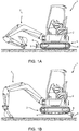
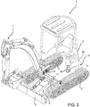
- Figures 1a and 2 discloses a work machine, i.e. a mini-excavator 1, comprising a machine base 2 rotatably mounted on an undercarriage 3 movable thanks to moving means, e.g. track bands 4, and a work blade, also known as dozer 5, pivotally carried by a boom 6 which is pivoted with respect to the machine base 2.
- Mini-excavator 1 further comprises a working element 7, e.g. a bucket carried by a hydraulically actuated boom, connected to machine base 2.
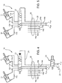
- Mini-excavator 1 comprises a hydraulic arrangement (not shown in detail in figures 1a and 2 but schematically represented in figure 3 ) configured to operate a first hydraulic actuator 11 voted to vary a width W of undercarriage defined by moving means, i.e. by track bands 4, and a second hydraulic actuator 12 voted to move boom 6 and consequently dozer 5.
- Hydraulic arrangement 10' as known in the prior art comprises a selection valve 13 configured to allow the passage of high pressure fluid from a source of fluid in pressure F HP of hydraulic arrangement 10' in only one of cylinders 11, 12. Respective hoses 11a, 11b and 12a, 1b fluidly connect selection valve 13 with respective openings of cylinders 11 and 12 and hoses 14a, 14b fluidly connect valve 13 to the high pressure fluid source F HP .
- Selection valve 13 is controlled by a pilot line which is configured to switch valve 13 so as to assume at least two operational positions. Pilot line may be a hydraulic pilot line or an electrically pilot line as known in the art.
- Hydraulic arrangement 10' may moreover comprise two hydraulic motors, more specifically a left motor 15 and a right motor 16, configured to operate moving means of mini-excavator 1, respectively left and right moving means, i.e. left and right tracks 4. Hydraulic motors 15 and 16 are fed by fluid in high pressure thanks to respective hoses 15a, 15b and 16a, 16b fluidly connecting respecting openings of motors 15 and 16 with the a high pressure fluid source F HP .
- Hoses 11a, 11b, 12a, 12b, 14a, 14b, 15a, 15b and 16a, 16b are high pressure hoses for operative fluid for oil hydraulic circuit of work machines as known in the art.
- Hoses 11a, 11b, 12a, 12b, 15a, 15b and 16a, 16b must pass from machine base 2 to undercarriage 3 through a swivel joint 20 (represented schematically by dot lines) positioned downstream with respect to valve 13 and upstream with respect to cylinders 11, 12 and motors 15, 16.
- hydraulic arrangement 10 comprises a selection valve 13 which is housed in undercarriage 3, i.e. it is positioned downstream with respect to swivel joint 20 and upstream with cylinders 11, 12.
- selection valve 13 is controlled thanks to a hydraulic pilot line 21 which may connected to a low pressure source F LP or to a discharge 23 by a control valve 24.
- selection valve 13 is controlled thanks to a electric pilot line 26.
- hydraulic pilot line 21 or electric pilot line 26 has to pass through swivel joint 20 from machine base 2 to undercarriage 3.
- selection valve 13 is disposed so that high pressure fluid from hoses 14a, 14b may pass through valve 13 to cylinder 12 to activate dozer 5 (see figures 3 and 4 ).
- Valve 13 is controlled by hydraulic pilot line 21 which, according to the embodiment of figure 4 , may be fluidly connected to discharge by valve 24.
- a proper electronic signal actuate valve 13 in the chosen position.
- selection valve 13 is disposed so that high pressure fluid from hoses 14a, 14b may pass through valve 13 to cylinder 11 to activate variation of width between tracks 4 (schema not represented) .
- Valve 13 is controlled by hydraulic pilot line 21 which, according to first embodiment, may be fluidly connected to low pressure fluid source through valve 24.
- the operation of the second embodiment is substantially the same of the above described operation of the first embodiment with the sole difference that a proper electronic signal in pilot line 26 actuate valve 13 in the chosen position instead of a hydraulic signal.
- selection valve 13 is controlled thanks to a signal given by a feedback line 30 which is entirely housed in said undercarriage 3.
- said signal is an hydraulic signal acquired by the pressure of operative fluid in inlet hose 12a of hydraulic cylinder 12.
- selection valve 13 may be actuated thanks to a hydraulic pilot line 21 which, when actuated by the operator e.g. pushing a specific button, is continuously connected to a low pressure source F LP .
- Selection valve 13 is further fluidly connected to inlet hose 12a of hydraulic cylinder 12 by feedback line 30 configured to allow the fluid in pressure in inlet hose 12a to switch selection valve 13 when such pressure is above a preset threshold. Accordingly, feedback line 30 hydraulic signal and low pressure fluid from pilot line 21 are two "and" condition to activate valve 13.
- the mentioned threshold is the pressure reached by working fluid in hose 12a when machine base 2 is lifted up, e.g. by pushing on the ground dozer 5 and the working element 7, so as to lift up machine base 2 (see figure 1b ).
- the weight of work machine 1 acts on cylinder of dozer 5 and cylinder 12 must supply a consequent load configured to support such function.
- hydraulic cylinder 12 In a first operative configuration, hydraulic cylinder 12 is used under a preset pressure threshold of working fluid in hose 12a and therefore selection valve 13 stay in a first position in which working fluid at high pressure flows to hydraulic cylinder 12 through valve 13; pilot signal 21 is inhibited to activate displacement of valve 13 by the fluid in hose 12a which pressure is under the preset pressure threshold.
- a second operative configuration ( figure 1b )
- user lifts machine base 2 by pushing dozer 5 and working arm 7 of the work machine 1 on the ground.
- Pressure of working fluid in hose 12a surmount the pressure threshold because cylinder 12 has to support machine weight.
- pressure of pilot signal 21 allow displacement of valve 13 which changes position and allows the fluidic connection between high pressure fluid source F HP to first cylinder 11.
- User may therefore vary width W of undercarriage 3. During such phase, since work machine 1 remains in the "lifted" configuration, user may continue to use cylinder 11 because pressure in hose 12a remains constant.
- selection valve 13 may be fluidly interposed between hydraulic cylinder 11 and at least one between motors 15 or 16, in the described exemplificative configuration only left motor 15, and controlled by hydraulic signal coming from feedback line 30 which fluidly connected inlet hose 12a of hydraulic cylinder 12 to selection valve 13.
- hydraulic cylinder 12 is continuously connected to high pressure source F HP by hoses 12a, 12b while left motor 15 and hydraulic cylinder 11 are selectively fluidly connected to high source pressure via hoses 14a, 14b in function of position of valve 13.
- hydraulic cylinder 12 In a first operative configuration ( figure 7 ), hydraulic cylinder 12 is used under a preset pressure threshold of working fluid in hose 12a and therefore selection valve 13 stay in a first position in which working fluid at high pressure flows from its source to left motor 15 through valve 13.
- a second operative configuration ( figure 8 )
- user lifts machine base 2 by pushing dozer 5 and working arm 7 of the work machine 1 on the ground.
- Pressure of working fluid in hose 12a surmount the pressure threshold because cylinder 12 has to support machine weight. Accordingly, such pressure activates displacement of valve 13 which changes position and allows the fluidic connection between high pressure fluid source F HP to first cylinder 11.
- User may therefore vary width W of undercarriage 3. During such phase, since work machine 1 remains in the "lifted" configuration, user may continue to use cylinder 11 because pressure in hose 12a remains constant.
- selection valve 13 may be fluidly interposed between hydraulic cylinder 11 and both motors 15 or 16 and controlled by hydraulic signal coming from feedback line 30 which fluidly connected inlet hose 12a of hydraulic cylinder 12 to selection valve 13.
- hydraulic cylinder 12 is continuously connected to high pressure source F HP by hoses 12a, 12b while both hoses 15a, 15b and 16a, 16b of respectively left and right motors 15, 16 and hydraulic cylinder 11 are selectively fluidly connected to high source pressure via hoses 14a, 14b in function of position of valve 13.
- hydraulic cylinder 12 is used under a preset pressure threshold of working fluid in hose 12a and therefore selection valve 13 stay in a first position in which working fluid at high pressure flows from its source to left and right motors 15 and 16 through valve 13.
- a second operative configuration (not shown), user lifts machine base 2 by pushing dozer 5 and working arm 7 of the work machine 1 on the ground.
- Pressure of working fluid in hose 12a surmount the pressure threshold because cylinder 12 has to support machine weight. Accordingly, such pressure activates displacement of valve 13 which changes position with the same effect of the above described fourth embodiment.
- selection valve 13 from machine base 2 to undercarriage 3 allows to reduce, of at least two units, the number of hoses which need to pass into swivel joint 20. In this way, swivel joint 20 may be designed smaller and therefore its costs and encumbrance are reduced.
- control of selection valve 13 may be hydraulically or electronically implemented, therefore increasing the versatility of hydraulic arrangement 10.
- control of selection valve 13 thanks to bypass line 30, allows to reduce further the number of hoses which need to pass into swivel joint 20.
- Such control allows to provide valve 13 between other elements of hydraulic arrangement 10, such as motors 15, 16 of work machine 1.
- selection valve 13 may be implemented in other way with respect to the described ones.
- feedback line 30 may be also provided as an electrical signal converted from a sensor configured to detect pressure in hose 12a.
- Selection valve 13 may be interposed with right motor 16 or may be again interposed between the two cylinders 11, 12.
Landscapes
- Engineering & Computer Science (AREA)
- Mining & Mineral Resources (AREA)
- Civil Engineering (AREA)
- General Engineering & Computer Science (AREA)
- Structural Engineering (AREA)
- Mechanical Engineering (AREA)
- Fluid-Pressure Circuits (AREA)
- Operation Control Of Excavators (AREA)
- Multiple-Way Valves (AREA)
- Lifting Devices For Agricultural Implements (AREA)
Abstract
Description
- The present invention concerns a work machine comprising a hydraulic arrangement for a selection valve, in particular a work machine comprising a hydraulic arrangement for controlling a selection valve configured to vary the width of the undercarriage and the operation of a work blade of the work machine.
- Mini-excavator is a work machine having a relative small weight (e.g. less than 1.8 tons) and voted to earth moving.
- Mini-excavator essentially comprises a machine base rotatably mounted on an undercarriage movable thanks to moving means, e.g. track bands, and a work blade, also known as dozer, pivotally carried by a boom which is pivoted with respect to the machine base.
- Width of undercarriage may be varied in function of the space through which the mini-excavator must pass. Indeed, in certain situation undercarriage should be retracted to a minimum width, e.g. during the passage in a narrow space, or should be extended to a maximum width, e.g. when a great stability is needed. Dozer may be controlled by controlling the operation boom.
- The above described operation of undercarriage and dozer are hydraulically operated thanks to an hydraulic arrangement essentially comprising a hydraulic cylinder configured to operate boom carrying the dozer, a hydraulic cylinder configured to vary the width of the undercarriage and a selection valve configured to switch the passage of operating fluid so as to control only one of the two aforementioned cylinders.
- Such selection valve is placed in the machine base and therefore at least four hoses (two per cylinder), suitable for the passage of high pressure fluid, have to be provided between selection valve and cylinders. Such hoses may be subject to loads and wear due to their long path from valve to cylinders.
- Moreover hoses have to pass through a swivel joint which connects machine base to the undercarriage and allows the relative motion of machine base with respect to undercarriage. Therefore, swivel joint needs to be dimensioned to allow the passage of at least such four hoses, therefore increasing its costs and dimensions.
- In view of the above, the need is felt to reduce the number of hoses passing through the swivel joint of a mini-excavator for controlling the hydraulic cylinders which control the dozer and the width of the undercarriage. Moreover, the need is felt to simplify the control of the two aforementioned cylinders in an economic way.
- An aim of the present invention is to satisfy the above mentioned needs.
- The aforementioned aim is reached by a work machine comprising a hydraulic arrangement as claimed in the appended set of claims.
- For a better understanding of the present invention, a preferred embodiment is described in the following, by way of a non-limiting example, with reference to the attached drawings wherein:
-
Figure 1a is a lateral schematic view of a known type mini-excavator in a first operative condition; -
Figure 1b is a lateral schematic view of a known type mini-excavator in a second operative condition; -
Figure 2 is a perspective view, with parts removed for sake of clarity, of a mini-excavator comprising a hydraulic arrangement as known in the prior art; -
Figure 3 is a scheme of the hydraulic arrangement for controlling dozer and undercarriage width-control cylinders as known in the prior art; -
Figure 4 is a scheme of a hydraulic arrangement for controlling dozer and undercarriage width-control cylinders according to a first embodiment of the present invention; -
Figure 5 is a scheme of a hydraulic arrangement for controlling dozer and undercarriage width-control cylinders according to a second embodiment of the present invention; -
Figure 6 is a scheme of a hydraulic arrangement for controlling dozer and undercarriage width-control cylinders according to a third embodiment of the present invention; -
Figures 7 and 8 are respective schemes of a hydraulic arrangement for controlling dozer and undercarriage width-control cylinders according to a fourth embodiment of the present invention in two different operative conditions, and -
Figure 9 is a scheme of a hydraulic arrangement for controlling dozer and undercarriage width-control cylinders according to a fifth embodiment of the present invention. -
Figures 1a and2 discloses a work machine, i.e. a mini-excavator 1, comprising amachine base 2 rotatably mounted on anundercarriage 3 movable thanks to moving means,e.g. track bands 4, and a work blade, also known asdozer 5, pivotally carried by aboom 6 which is pivoted with respect to themachine base 2. Mini-excavator 1 further comprises a workingelement 7, e.g. a bucket carried by a hydraulically actuated boom, connected tomachine base 2. - Mini-excavator 1 comprises a hydraulic arrangement (not shown in detail in
figures 1a and2 but schematically represented infigure 3 ) configured to operate a firsthydraulic actuator 11 voted to vary a width W of undercarriage defined by moving means, i.e. bytrack bands 4, and a secondhydraulic actuator 12 voted to moveboom 6 and consequentlydozer 5. - Hydraulic arrangement 10' as known in the prior art comprises a
selection valve 13 configured to allow the passage of high pressure fluid from a source of fluid in pressure FHP of hydraulic arrangement 10' in only one ofcylinders Respective hoses selection valve 13 with respective openings ofcylinders hoses valve 13 to the high pressure fluid source FHP. Selection valve 13 is controlled by a pilot line which is configured to switchvalve 13 so as to assume at least two operational positions. Pilot line may be a hydraulic pilot line or an electrically pilot line as known in the art. - Hydraulic arrangement 10' may moreover comprise two hydraulic motors, more specifically a
left motor 15 and aright motor 16, configured to operate moving means of mini-excavator 1, respectively left and right moving means, i.e. left andright tracks 4.Hydraulic motors respective hoses motors - Hoses 11a, 11b, 12a, 12b, 14a, 14b, 15a, 15b and 16a, 16b are high pressure hoses for operative fluid for oil hydraulic circuit of work machines as known in the art.
-
Hoses machine base 2 to undercarriage 3 through a swivel joint 20 (represented schematically by dot lines) positioned downstream with respect tovalve 13 and upstream with respect tocylinders motors - According to the present invention,
hydraulic arrangement 10 comprises aselection valve 13 which is housed inundercarriage 3, i.e. it is positioned downstream with respect toswivel joint 20 and upstream withcylinders - According to a first embodiment of the present invention, shown in
figure 4 ,selection valve 13 is controlled thanks to ahydraulic pilot line 21 which may connected to a low pressure source FLP or to adischarge 23 by acontrol valve 24. - According to a second embodiment of the present invention, shown in
figure 5 ,selection valve 13 is controlled thanks to aelectric pilot line 26. - In both embodiments
hydraulic pilot line 21 orelectric pilot line 26 has to pass throughswivel joint 20 frommachine base 2 toundercarriage 3. - The operation of
hydraulic arrangement 10 according to the two aforementioned embodiments of present invention is the following. - In a first operative
configuration selection valve 13 is disposed so that high pressure fluid fromhoses valve 13 tocylinder 12 to activate dozer 5 (seefigures 3 and4 ). Valve 13 is controlled byhydraulic pilot line 21 which, according to the embodiment offigure 4 , may be fluidly connected to discharge byvalve 24. According to embodiment offigure 5 , a proper electronic signal actuatevalve 13 in the chosen position. - In a second operative
configuration selection valve 13 is disposed so that high pressure fluid fromhoses valve 13 tocylinder 11 to activate variation of width between tracks 4 (schema not represented) . Valve 13 is controlled byhydraulic pilot line 21 which, according to first embodiment, may be fluidly connected to low pressure fluid source throughvalve 24. The operation of the second embodiment is substantially the same of the above described operation of the first embodiment with the sole difference that a proper electronic signal inpilot line 26 actuatevalve 13 in the chosen position instead of a hydraulic signal. - According to further aspect of the present invention, shown in
figures 5 to 7 ,selection valve 13 is controlled thanks to a signal given by afeedback line 30 which is entirely housed in saidundercarriage 3. In the aforementioned embodiment said signal is an hydraulic signal acquired by the pressure of operative fluid ininlet hose 12a ofhydraulic cylinder 12. - As disclosed in a third embodiment of the present invention, shown in
figure 6 ,selection valve 13 may be actuated thanks to ahydraulic pilot line 21 which, when actuated by the operator e.g. pushing a specific button, is continuously connected to a low pressure source FLP. Selection valve 13 is further fluidly connected toinlet hose 12a ofhydraulic cylinder 12 byfeedback line 30 configured to allow the fluid in pressure ininlet hose 12a to switchselection valve 13 when such pressure is above a preset threshold. Accordingly,feedback line 30 hydraulic signal and low pressure fluid frompilot line 21 are two "and" condition to activatevalve 13. - The mentioned threshold is the pressure reached by working fluid in
hose 12a whenmachine base 2 is lifted up, e.g. by pushing on theground dozer 5 and theworking element 7, so as to lift up machine base 2 (seefigure 1b ). In such configuration the weight ofwork machine 1 acts on cylinder ofdozer 5 andcylinder 12 must supply a consequent load configured to support such function. - The operation of
hydraulic arrangement 10 according to the aforementioned embodiment of present invention is the following. - In a first operative configuration,
hydraulic cylinder 12 is used under a preset pressure threshold of working fluid inhose 12a and thereforeselection valve 13 stay in a first position in which working fluid at high pressure flows tohydraulic cylinder 12 throughvalve 13;pilot signal 21 is inhibited to activate displacement ofvalve 13 by the fluid inhose 12a which pressure is under the preset pressure threshold. - In a second operative configuration (
figure 1b ), userlifts machine base 2 by pushingdozer 5 and workingarm 7 of thework machine 1 on the ground. Pressure of working fluid inhose 12a surmount the pressure threshold becausecylinder 12 has to support machine weight. Accordingly, pressure ofpilot signal 21 allow displacement ofvalve 13 which changes position and allows the fluidic connection between high pressure fluid source FHP tofirst cylinder 11. User may therefore vary width W ofundercarriage 3. During such phase, sincework machine 1 remains in the "lifted" configuration, user may continue to usecylinder 11 because pressure inhose 12a remains constant. - When the desired width W is reached, user will lower
machine base 2 and thereforedozer 5 will no more support machine weight. Pressure inhose 12a will therefore decrease under the preset threshold andpilot signal 21 returns to its inhibition state and valves returns in the positon according to the described first operation configuration. - As disclosed in a fourth embodiment of the present invention, shown in
figures 7 and 8 ,selection valve 13 may be fluidly interposed betweenhydraulic cylinder 11 and at least one betweenmotors motor 15, and controlled by hydraulic signal coming fromfeedback line 30 which fluidly connectedinlet hose 12a ofhydraulic cylinder 12 toselection valve 13. - In such configuration of
hydraulic arrangement 10,hydraulic cylinder 12 is continuously connected to high pressure source FHP byhoses left motor 15 andhydraulic cylinder 11 are selectively fluidly connected to high source pressure viahoses valve 13. - In a first operative configuration (
figure 7 ),hydraulic cylinder 12 is used under a preset pressure threshold of working fluid inhose 12a and thereforeselection valve 13 stay in a first position in which working fluid at high pressure flows from its source to leftmotor 15 throughvalve 13. - In a second operative configuration (
figure 8 ), userlifts machine base 2 by pushingdozer 5 and workingarm 7 of thework machine 1 on the ground. Pressure of working fluid inhose 12a surmount the pressure threshold becausecylinder 12 has to support machine weight. Accordingly, such pressure activates displacement ofvalve 13 which changes position and allows the fluidic connection between high pressure fluid source FHP tofirst cylinder 11. User may therefore vary width W ofundercarriage 3. During such phase, sincework machine 1 remains in the "lifted" configuration, user may continue to usecylinder 11 because pressure inhose 12a remains constant. - When the desired width W is reached, user will lower
machine base 2 and thereforedozer 5 will no more support machine weight. Pressure inhose 12a will therefore decrease under the preset threshold andselection valve 13 returns to in the positon according to the described first operation configuration. - As disclosed in a fifth embodiment of the present invention, shown in
figure 9 ,selection valve 13 may be fluidly interposed betweenhydraulic cylinder 11 and bothmotors feedback line 30 which fluidly connectedinlet hose 12a ofhydraulic cylinder 12 toselection valve 13. - In such configuration of
hydraulic arrangement 10,hydraulic cylinder 12 is continuously connected to high pressure source FHP byhoses hoses right motors hydraulic cylinder 11 are selectively fluidly connected to high source pressure viahoses valve 13. - In the exemplificative shown operative configuration of
figure 9 ,hydraulic cylinder 12 is used under a preset pressure threshold of working fluid inhose 12a and thereforeselection valve 13 stay in a first position in which working fluid at high pressure flows from its source to left andright motors valve 13. - In a second operative configuration (not shown), user
lifts machine base 2 by pushingdozer 5 and workingarm 7 of thework machine 1 on the ground. Pressure of working fluid inhose 12a surmount the pressure threshold becausecylinder 12 has to support machine weight. Accordingly, such pressure activates displacement ofvalve 13 which changes position with the same effect of the above described fourth embodiment. - In view of the foregoing, the advantages of
hydraulic arrangement 10 according to the invention are apparent. - The displacement of
selection valve 13 frommachine base 2 toundercarriage 3 allows to reduce, of at least two units, the number of hoses which need to pass into swivel joint 20. In this way, swivel joint 20 may be designed smaller and therefore its costs and encumbrance are reduced. - Moreover, since hoses of
cylinders valve 13 tocylinders - The control of
selection valve 13 may be hydraulically or electronically implemented, therefore increasing the versatility ofhydraulic arrangement 10. - Further, the control of
selection valve 13 thanks to bypassline 30, allows to reduce further the number of hoses which need to pass into swivel joint 20. Such control allows to providevalve 13 between other elements ofhydraulic arrangement 10, such asmotors work machine 1. - It has to be noted that according to the embodiments of
figures 6 to 8 a cost reduction can be further achieved by eliminating electric and/or hydraulic components configured to control movement ofselection valve 13. - It is clear that modifications can be made to the described
hydraulic arrangement 10 which do not extend beyond the scope of protection defined by the claims. - For example, it is clear that the actuation of
selection valve 13 may be implemented in other way with respect to the described ones. - Moreover, other elements than the described may be present into the
hydraulic arrangement 10 of the present invention. - Further, it is clear that
feedback line 30 may be also provided as an electrical signal converted from a sensor configured to detect pressure inhose 12a.Selection valve 13 may be interposed withright motor 16 or may be again interposed between the twocylinders - Finally, described embodiments may be combined together without departing from the scope of the appended set of claims.
Claims (11)
- Work machine (1) comprising a machine base (2) mounted movably over an undercarriage (3) and a hydraulic arrangement (10), said hydraulic arrangement (10) comprising:- a first cylinder (12) configured for operating a working blade (5) of said work machine (1),- a second cylinder (11) configured to vary the width (W) of said undercarriage (3),- a source of fluid at high pressure (FHP) which is fluidly connected to said first and second cylinders (11, 12) and which is housed in said machine base (2), and- a selection valve (13) which is fluidly interposed between said source (FHP) and at least one of said first and second cylinders (11, 12), wherein said valve is housed in said undercarriage (3).
- Work machine according to claim 1, wherein said hydraulic arrangement comprises a pilot line (21) suitable for fluidly connecting a source of fluid housed in said machine base (2) to said selection valve (13) so as to switch its position.
- Work machine according to claim 1, wherein said hydraulic arrangement comprises an electrical pilot line (26) suitable for electrically connecting an electrical source housed in said machine base (2) to said selection valve (13) so as to switch its position.
- Work machine according to claim 1, wherein said hydraulic arrangement comprises a feedback line (30) connected to said selection valve (13) so as to switch its position, said feedback line (30) being entirely housed in said undercarriage (3).
- Work machine according to claim 4, wherein said pilot line is a hydraulic feedback line (30).
- Work machine according to any of claims 4 or 5, wherein said pilot line is configured to detect a pressure value in an inlet hose (12a) of said first cylinder (12) and to switch position of said valve (13) when said pressure overcome a preset threshold.
- Work machine according to claim 6, wherein said pressure threshold is the pressure in said inlet hose (12a) reached when said work machine (1) is in lifted position.
- Work machine according to any of claims 6 or 7, wherein said feedback line (30) is a hose fluidly connecting said valve (13) to said inlet hose (12a).
- Work machine according to any of the preceding claims, wherein said valve (13) is fluidly interposed between said source and both said first and second cylinders (11, 12) .
- Work machine according to any of claims 6 to 8, wherein said valve (13) is fluidly interposed between said source,one between said first and second cylinders (11, 12) and at least one motor (14, 15) of said work machine (1).
- Work machine according to any of claims 6 to 8, wherein said valve (13) is fluidly interposed between said source, one between said first and second cylinders (11, 12) and both motors (14, 15) of said work machine (1).
Applications Claiming Priority (1)
| Application Number | Priority Date | Filing Date | Title |
|---|---|---|---|
| IT102018000003950A IT201800003950A1 (en) | 2018-03-26 | 2018-03-26 | WORKING MACHINE INCLUDING A HYDRAULIC ARRANGEMENT FOR A SELECTOR VALVE |
Publications (2)
| Publication Number | Publication Date |
|---|---|
| EP3546659A1 true EP3546659A1 (en) | 2019-10-02 |
| EP3546659B1 EP3546659B1 (en) | 2023-03-01 |
Family
ID=62530504
Family Applications (1)
| Application Number | Title | Priority Date | Filing Date |
|---|---|---|---|
| EP19163653.9A Active EP3546659B1 (en) | 2018-03-26 | 2019-03-19 | Work machine comprising a hydraulic arrangement for a selection valve |
Country Status (4)
| Country | Link |
|---|---|
| US (1) | US10767343B2 (en) |
| EP (1) | EP3546659B1 (en) |
| BR (1) | BR102019005978B1 (en) |
| IT (1) | IT201800003950A1 (en) |
Cited By (2)
| Publication number | Priority date | Publication date | Assignee | Title |
|---|---|---|---|---|
| IT202300014151A1 (en) | 2023-07-06 | 2025-01-06 | Cnh Ind Italia Spa | IMPROVED ROTARY JOINT ASSEMBLY FOR A WORK VEHICLE AND RELATED HYDRAULIC ARRANGEMENT |
| IT202300017649A1 (en) | 2023-08-28 | 2025-02-28 | Cnh Ind Italia Spa | IMPROVED ROTARY JOINT ASSEMBLY FOR A WORK VEHICLE AND RELATED HYDRAULIC ARRANGEMENT |
Citations (2)
| Publication number | Priority date | Publication date | Assignee | Title |
|---|---|---|---|---|
| JPH05331877A (en) * | 1992-06-02 | 1993-12-14 | Kubota Corp | Backhoe |
| JP3330683B2 (en) * | 1993-06-25 | 2002-09-30 | 小松ゼノア株式会社 | Power shovel |
Family Cites Families (2)
| Publication number | Priority date | Publication date | Assignee | Title |
|---|---|---|---|---|
| CA2696070A1 (en) * | 2007-08-13 | 2009-02-19 | Clark Equipment Company | Hydraulic control system for a swiveling construction machine |
| EP2136057B1 (en) * | 2008-06-19 | 2021-12-08 | Vitesco Technologies GmbH | Fuel quality dependent injection timing control for an internal combustion engine |
-
2018
- 2018-03-26 IT IT102018000003950A patent/IT201800003950A1/en unknown
-
2019
- 2019-03-19 EP EP19163653.9A patent/EP3546659B1/en active Active
- 2019-03-26 US US16/365,635 patent/US10767343B2/en active Active
- 2019-03-26 BR BR102019005978-8A patent/BR102019005978B1/en active IP Right Grant
Patent Citations (2)
| Publication number | Priority date | Publication date | Assignee | Title |
|---|---|---|---|---|
| JPH05331877A (en) * | 1992-06-02 | 1993-12-14 | Kubota Corp | Backhoe |
| JP3330683B2 (en) * | 1993-06-25 | 2002-09-30 | 小松ゼノア株式会社 | Power shovel |
Cited By (3)
| Publication number | Priority date | Publication date | Assignee | Title |
|---|---|---|---|---|
| IT202300014151A1 (en) | 2023-07-06 | 2025-01-06 | Cnh Ind Italia Spa | IMPROVED ROTARY JOINT ASSEMBLY FOR A WORK VEHICLE AND RELATED HYDRAULIC ARRANGEMENT |
| IT202300017649A1 (en) | 2023-08-28 | 2025-02-28 | Cnh Ind Italia Spa | IMPROVED ROTARY JOINT ASSEMBLY FOR A WORK VEHICLE AND RELATED HYDRAULIC ARRANGEMENT |
| EP4517008A1 (en) | 2023-08-28 | 2025-03-05 | CNH Industrial Italia S.p.A. | Improved swivel joint assembly for a work vehicle and related hydraulic arrangement |
Also Published As
| Publication number | Publication date |
|---|---|
| US20190292749A1 (en) | 2019-09-26 |
| IT201800003950A1 (en) | 2019-09-26 |
| US10767343B2 (en) | 2020-09-08 |
| BR102019005978B1 (en) | 2024-01-02 |
| EP3546659B1 (en) | 2023-03-01 |
| BR102019005978A2 (en) | 2019-11-05 |
Similar Documents
| Publication | Publication Date | Title |
|---|---|---|
| CN105008724B (en) | Hydraulic drives for construction machinery | |
| KR101316416B1 (en) | Hydraulic drive device for hydraulic working machine | |
| US8671824B2 (en) | Hydraulic control system | |
| EP2354331B1 (en) | Hydraulic drive device for hydraulic excavator | |
| CN106574642B (en) | The hydraulic control device of engineering machinery | |
| KR101975063B1 (en) | Construction machinery and hydraulic circuit thereof | |
| US20130042935A1 (en) | Hydraulic switching mechanism for mobile hydraulics, mobile hydraulic machine and valve unit | |
| CN102245908A (en) | Hydraulic drive for construction machine | |
| JP6656913B2 (en) | Working machine hydraulic system | |
| US9797419B2 (en) | Hydraulic system with energy recovery | |
| CN112639296B (en) | Hydraulic drive device for traveling construction machine | |
| US10767343B2 (en) | Work machine comprising a hydraulic arrangement for a selection valve | |
| US20020011013A1 (en) | Hydraulic excavating mobile machine | |
| CN110799710B (en) | Boom control system for construction machinery | |
| DE102014102336A1 (en) | Control valve device with a floating position | |
| US5794511A (en) | Apparatus and method for controlling multiple fluid cylinders | |
| JP7071198B2 (en) | Hydraulic circuit of work vehicle | |
| JP4502890B2 (en) | Backhoe hydraulic circuit structure | |
| JP7005416B2 (en) | Hydraulic circuit of construction machinery | |
| JP2005140153A (en) | Hydraulic control equipment for construction machinery | |
| EP1522740A1 (en) | A cushion valve for hydraulic remote controls of hydraulic directional valves | |
| KR100884870B1 (en) | Variable priority system for excavator control valve | |
| CN217976873U (en) | Control valve device and hydraulically driven machine equipped with the control valve device | |
| CN105874215A (en) | Control system for work machine | |
| US11898329B2 (en) | Hydraulic control circuit for implement |
Legal Events
| Date | Code | Title | Description |
|---|---|---|---|
| PUAI | Public reference made under article 153(3) epc to a published international application that has entered the european phase |
Free format text: ORIGINAL CODE: 0009012 |
|
| STAA | Information on the status of an ep patent application or granted ep patent |
Free format text: STATUS: THE APPLICATION HAS BEEN PUBLISHED |
|
| AK | Designated contracting states |
Kind code of ref document: A1 Designated state(s): AL AT BE BG CH CY CZ DE DK EE ES FI FR GB GR HR HU IE IS IT LI LT LU LV MC MK MT NL NO PL PT RO RS SE SI SK SM TR |
|
| AX | Request for extension of the european patent |
Extension state: BA ME |
|
| STAA | Information on the status of an ep patent application or granted ep patent |
Free format text: STATUS: REQUEST FOR EXAMINATION WAS MADE |
|
| 17P | Request for examination filed |
Effective date: 20200402 |
|
| RBV | Designated contracting states (corrected) |
Designated state(s): AL AT BE BG CH CY CZ DE DK EE ES FI FR GB GR HR HU IE IS IT LI LT LU LV MC MK MT NL NO PL PT RO RS SE SI SK SM TR |
|
| STAA | Information on the status of an ep patent application or granted ep patent |
Free format text: STATUS: EXAMINATION IS IN PROGRESS |
|
| 17Q | First examination report despatched |
Effective date: 20210625 |
|
| GRAJ | Information related to disapproval of communication of intention to grant by the applicant or resumption of examination proceedings by the epo deleted |
Free format text: ORIGINAL CODE: EPIDOSDIGR1 |
|
| GRAP | Despatch of communication of intention to grant a patent |
Free format text: ORIGINAL CODE: EPIDOSNIGR1 |
|
| GRAP | Despatch of communication of intention to grant a patent |
Free format text: ORIGINAL CODE: EPIDOSNIGR1 |
|
| STAA | Information on the status of an ep patent application or granted ep patent |
Free format text: STATUS: GRANT OF PATENT IS INTENDED |
|
| RIC1 | Information provided on ipc code assigned before grant |
Ipc: E02F 3/815 20060101ALN20220802BHEP Ipc: B62D 55/084 20060101ALI20220802BHEP Ipc: B60B 35/10 20060101ALI20220802BHEP Ipc: E02F 9/02 20060101AFI20220802BHEP |
|
| RIC1 | Information provided on ipc code assigned before grant |
Ipc: E02F 3/815 20060101ALN20220816BHEP Ipc: B62D 55/084 20060101ALI20220816BHEP Ipc: B60B 35/10 20060101ALI20220816BHEP Ipc: E02F 9/02 20060101AFI20220816BHEP |
|
| INTG | Intention to grant announced |
Effective date: 20220831 |
|
| RIC1 | Information provided on ipc code assigned before grant |
Ipc: E02F 3/815 20060101ALN20220823BHEP Ipc: B62D 55/084 20060101ALI20220823BHEP Ipc: B60B 35/10 20060101ALI20220823BHEP Ipc: E02F 9/02 20060101AFI20220823BHEP |
|
| GRAS | Grant fee paid |
Free format text: ORIGINAL CODE: EPIDOSNIGR3 |
|
| GRAA | (expected) grant |
Free format text: ORIGINAL CODE: 0009210 |
|
| STAA | Information on the status of an ep patent application or granted ep patent |
Free format text: STATUS: THE PATENT HAS BEEN GRANTED |
|
| AK | Designated contracting states |
Kind code of ref document: B1 Designated state(s): AL AT BE BG CH CY CZ DE DK EE ES FI FR GB GR HR HU IE IS IT LI LT LU LV MC MK MT NL NO PL PT RO RS SE SI SK SM TR |
|
| REG | Reference to a national code |
Ref country code: GB Ref legal event code: FG4D |
|
| REG | Reference to a national code |
Ref country code: CH Ref legal event code: EP Ref country code: AT Ref legal event code: REF Ref document number: 1551056 Country of ref document: AT Kind code of ref document: T Effective date: 20230315 |
|
| REG | Reference to a national code |
Ref country code: DE Ref legal event code: R096 Ref document number: 602019025725 Country of ref document: DE |
|
| REG | Reference to a national code |
Ref country code: IE Ref legal event code: FG4D |
|
| REG | Reference to a national code |
Ref country code: LT Ref legal event code: MG9D |
|
| RAP4 | Party data changed (patent owner data changed or rights of a patent transferred) |
Owner name: CNH INDUSTRIAL ITALIA S.P.A. |
|
| REG | Reference to a national code |
Ref country code: NL Ref legal event code: MP Effective date: 20230301 |
|
| PG25 | Lapsed in a contracting state [announced via postgrant information from national office to epo] |
Ref country code: RS Free format text: LAPSE BECAUSE OF FAILURE TO SUBMIT A TRANSLATION OF THE DESCRIPTION OR TO PAY THE FEE WITHIN THE PRESCRIBED TIME-LIMIT Effective date: 20230301 Ref country code: NO Free format text: LAPSE BECAUSE OF FAILURE TO SUBMIT A TRANSLATION OF THE DESCRIPTION OR TO PAY THE FEE WITHIN THE PRESCRIBED TIME-LIMIT Effective date: 20230601 Ref country code: LV Free format text: LAPSE BECAUSE OF FAILURE TO SUBMIT A TRANSLATION OF THE DESCRIPTION OR TO PAY THE FEE WITHIN THE PRESCRIBED TIME-LIMIT Effective date: 20230301 Ref country code: LT Free format text: LAPSE BECAUSE OF FAILURE TO SUBMIT A TRANSLATION OF THE DESCRIPTION OR TO PAY THE FEE WITHIN THE PRESCRIBED TIME-LIMIT Effective date: 20230301 Ref country code: HR Free format text: LAPSE BECAUSE OF FAILURE TO SUBMIT A TRANSLATION OF THE DESCRIPTION OR TO PAY THE FEE WITHIN THE PRESCRIBED TIME-LIMIT Effective date: 20230301 Ref country code: ES Free format text: LAPSE BECAUSE OF FAILURE TO SUBMIT A TRANSLATION OF THE DESCRIPTION OR TO PAY THE FEE WITHIN THE PRESCRIBED TIME-LIMIT Effective date: 20230301 |
|
| REG | Reference to a national code |
Ref country code: AT Ref legal event code: MK05 Ref document number: 1551056 Country of ref document: AT Kind code of ref document: T Effective date: 20230301 |
|
| PG25 | Lapsed in a contracting state [announced via postgrant information from national office to epo] |
Ref country code: SE Free format text: LAPSE BECAUSE OF FAILURE TO SUBMIT A TRANSLATION OF THE DESCRIPTION OR TO PAY THE FEE WITHIN THE PRESCRIBED TIME-LIMIT Effective date: 20230301 Ref country code: PL Free format text: LAPSE BECAUSE OF FAILURE TO SUBMIT A TRANSLATION OF THE DESCRIPTION OR TO PAY THE FEE WITHIN THE PRESCRIBED TIME-LIMIT Effective date: 20230301 Ref country code: NL Free format text: LAPSE BECAUSE OF FAILURE TO SUBMIT A TRANSLATION OF THE DESCRIPTION OR TO PAY THE FEE WITHIN THE PRESCRIBED TIME-LIMIT Effective date: 20230301 Ref country code: GR Free format text: LAPSE BECAUSE OF FAILURE TO SUBMIT A TRANSLATION OF THE DESCRIPTION OR TO PAY THE FEE WITHIN THE PRESCRIBED TIME-LIMIT Effective date: 20230602 Ref country code: FI Free format text: LAPSE BECAUSE OF FAILURE TO SUBMIT A TRANSLATION OF THE DESCRIPTION OR TO PAY THE FEE WITHIN THE PRESCRIBED TIME-LIMIT Effective date: 20230301 |
|
| PG25 | Lapsed in a contracting state [announced via postgrant information from national office to epo] |
Ref country code: SM Free format text: LAPSE BECAUSE OF FAILURE TO SUBMIT A TRANSLATION OF THE DESCRIPTION OR TO PAY THE FEE WITHIN THE PRESCRIBED TIME-LIMIT Effective date: 20230301 Ref country code: RO Free format text: LAPSE BECAUSE OF FAILURE TO SUBMIT A TRANSLATION OF THE DESCRIPTION OR TO PAY THE FEE WITHIN THE PRESCRIBED TIME-LIMIT Effective date: 20230301 Ref country code: PT Free format text: LAPSE BECAUSE OF FAILURE TO SUBMIT A TRANSLATION OF THE DESCRIPTION OR TO PAY THE FEE WITHIN THE PRESCRIBED TIME-LIMIT Effective date: 20230703 Ref country code: EE Free format text: LAPSE BECAUSE OF FAILURE TO SUBMIT A TRANSLATION OF THE DESCRIPTION OR TO PAY THE FEE WITHIN THE PRESCRIBED TIME-LIMIT Effective date: 20230301 Ref country code: CZ Free format text: LAPSE BECAUSE OF FAILURE TO SUBMIT A TRANSLATION OF THE DESCRIPTION OR TO PAY THE FEE WITHIN THE PRESCRIBED TIME-LIMIT Effective date: 20230301 Ref country code: AT Free format text: LAPSE BECAUSE OF FAILURE TO SUBMIT A TRANSLATION OF THE DESCRIPTION OR TO PAY THE FEE WITHIN THE PRESCRIBED TIME-LIMIT Effective date: 20230301 |
|
| REG | Reference to a national code |
Ref country code: CH Ref legal event code: PL |
|
| PG25 | Lapsed in a contracting state [announced via postgrant information from national office to epo] |
Ref country code: SK Free format text: LAPSE BECAUSE OF FAILURE TO SUBMIT A TRANSLATION OF THE DESCRIPTION OR TO PAY THE FEE WITHIN THE PRESCRIBED TIME-LIMIT Effective date: 20230301 Ref country code: IS Free format text: LAPSE BECAUSE OF FAILURE TO SUBMIT A TRANSLATION OF THE DESCRIPTION OR TO PAY THE FEE WITHIN THE PRESCRIBED TIME-LIMIT Effective date: 20230701 |
|
| REG | Reference to a national code |
Ref country code: BE Ref legal event code: MM Effective date: 20230331 |
|
| REG | Reference to a national code |
Ref country code: DE Ref legal event code: R097 Ref document number: 602019025725 Country of ref document: DE |
|
| PG25 | Lapsed in a contracting state [announced via postgrant information from national office to epo] |
Ref country code: LU Free format text: LAPSE BECAUSE OF NON-PAYMENT OF DUE FEES Effective date: 20230319 |
|
| PLBE | No opposition filed within time limit |
Free format text: ORIGINAL CODE: 0009261 |
|
| STAA | Information on the status of an ep patent application or granted ep patent |
Free format text: STATUS: NO OPPOSITION FILED WITHIN TIME LIMIT |
|
| PG25 | Lapsed in a contracting state [announced via postgrant information from national office to epo] |
Ref country code: MC Free format text: LAPSE BECAUSE OF FAILURE TO SUBMIT A TRANSLATION OF THE DESCRIPTION OR TO PAY THE FEE WITHIN THE PRESCRIBED TIME-LIMIT Effective date: 20230301 |
|
| REG | Reference to a national code |
Ref country code: IE Ref legal event code: MM4A |
|
| PG25 | Lapsed in a contracting state [announced via postgrant information from national office to epo] |
Ref country code: SI Free format text: LAPSE BECAUSE OF FAILURE TO SUBMIT A TRANSLATION OF THE DESCRIPTION OR TO PAY THE FEE WITHIN THE PRESCRIBED TIME-LIMIT Effective date: 20230301 Ref country code: MC Free format text: LAPSE BECAUSE OF FAILURE TO SUBMIT A TRANSLATION OF THE DESCRIPTION OR TO PAY THE FEE WITHIN THE PRESCRIBED TIME-LIMIT Effective date: 20230301 Ref country code: LI Free format text: LAPSE BECAUSE OF NON-PAYMENT OF DUE FEES Effective date: 20230331 Ref country code: IE Free format text: LAPSE BECAUSE OF NON-PAYMENT OF DUE FEES Effective date: 20230319 Ref country code: DK Free format text: LAPSE BECAUSE OF FAILURE TO SUBMIT A TRANSLATION OF THE DESCRIPTION OR TO PAY THE FEE WITHIN THE PRESCRIBED TIME-LIMIT Effective date: 20230301 Ref country code: CH Free format text: LAPSE BECAUSE OF NON-PAYMENT OF DUE FEES Effective date: 20230331 |
|
| 26N | No opposition filed |
Effective date: 20231204 |
|
| PG25 | Lapsed in a contracting state [announced via postgrant information from national office to epo] |
Ref country code: BE Free format text: LAPSE BECAUSE OF NON-PAYMENT OF DUE FEES Effective date: 20230331 |
|
| PG25 | Lapsed in a contracting state [announced via postgrant information from national office to epo] |
Ref country code: BG Free format text: LAPSE BECAUSE OF FAILURE TO SUBMIT A TRANSLATION OF THE DESCRIPTION OR TO PAY THE FEE WITHIN THE PRESCRIBED TIME-LIMIT Effective date: 20230301 |
|
| PG25 | Lapsed in a contracting state [announced via postgrant information from national office to epo] |
Ref country code: BG Free format text: LAPSE BECAUSE OF FAILURE TO SUBMIT A TRANSLATION OF THE DESCRIPTION OR TO PAY THE FEE WITHIN THE PRESCRIBED TIME-LIMIT Effective date: 20230301 |
|
| PG25 | Lapsed in a contracting state [announced via postgrant information from national office to epo] |
Ref country code: CY Free format text: LAPSE BECAUSE OF FAILURE TO SUBMIT A TRANSLATION OF THE DESCRIPTION OR TO PAY THE FEE WITHIN THE PRESCRIBED TIME-LIMIT; INVALID AB INITIO Effective date: 20190319 |
|
| PG25 | Lapsed in a contracting state [announced via postgrant information from national office to epo] |
Ref country code: HU Free format text: LAPSE BECAUSE OF FAILURE TO SUBMIT A TRANSLATION OF THE DESCRIPTION OR TO PAY THE FEE WITHIN THE PRESCRIBED TIME-LIMIT; INVALID AB INITIO Effective date: 20190319 |
|
| PG25 | Lapsed in a contracting state [announced via postgrant information from national office to epo] |
Ref country code: TR Free format text: LAPSE BECAUSE OF FAILURE TO SUBMIT A TRANSLATION OF THE DESCRIPTION OR TO PAY THE FEE WITHIN THE PRESCRIBED TIME-LIMIT Effective date: 20230301 |
|
| PGFP | Annual fee paid to national office [announced via postgrant information from national office to epo] |
Ref country code: GB Payment date: 20260319 Year of fee payment: 8 |
|
| PGFP | Annual fee paid to national office [announced via postgrant information from national office to epo] |
Ref country code: DE Payment date: 20260320 Year of fee payment: 8 |
|
| PGFP | Annual fee paid to national office [announced via postgrant information from national office to epo] |
Ref country code: IT Payment date: 20260320 Year of fee payment: 8 |
|
| PGFP | Annual fee paid to national office [announced via postgrant information from national office to epo] |
Ref country code: FR Payment date: 20260323 Year of fee payment: 8 |