EP3546636A1 - A framework for washing and/or drying devices - Google Patents
A framework for washing and/or drying devices Download PDFInfo
- Publication number
- EP3546636A1 EP3546636A1 EP18207688.5A EP18207688A EP3546636A1 EP 3546636 A1 EP3546636 A1 EP 3546636A1 EP 18207688 A EP18207688 A EP 18207688A EP 3546636 A1 EP3546636 A1 EP 3546636A1
- Authority
- EP
- European Patent Office
- Prior art keywords
- bottom support
- support
- front support
- housing
- snap
- Prior art date
- Legal status (The legal status is an assumption and is not a legal conclusion. Google has not performed a legal analysis and makes no representation as to the accuracy of the status listed.)
- Granted
Links
Images


Classifications
-
- D—TEXTILES; PAPER
- D06—TREATMENT OF TEXTILES OR THE LIKE; LAUNDERING; FLEXIBLE MATERIALS NOT OTHERWISE PROVIDED FOR
- D06F—LAUNDERING, DRYING, IRONING, PRESSING OR FOLDING TEXTILE ARTICLES
- D06F39/00—Details of washing machines not specific to a single type of machines covered by groups D06F9/00 - D06F27/00
- D06F39/12—Casings; Tubs
Definitions
- the present invention relates to frameworks provided at the washing and/or drying devices.
- the washing devices like washing machines, and the drying devices comprise at least one body and at least one drum in which textile products to be washed and/or dried are placed.
- said drum is located on a framework inside the body.
- Said framework generally comprises a bottom support and a front support.
- Said front support comprises at least one opening which allows access into the drum, wherein the bottom support may comprise multiple compartments in which various components of the washing and/or drying device (such as a heat exchanger, a water tank, a detergent tank) are located.
- frameworks used for the washing and/or drying devices are produced such that at least two different pieces are produced independently from each other and then joined together.
- said bottom support and the front support are produced separately, and then, these two pieces are fixed to each other.
- this fixing operation may be troublesome.
- Patent document no. US2006230630A1 covered by the known art discloses a drying device.
- mounting of the front support to the bottom support is such that protrusions provided at the front support are placed to the housings which are provided at the bottom support.
- the bottom support and the front support are connected to each other at only one axis. In other words, connection of the bottom support and the front support is poor. For that reason, problems arise such as the framework obtained being not durable enough.
- Said framework comprises at least one bottom support; at least one front support suitable for being connected to the bottom support; at least one connecting pin provided at the front support or the bottom support; at least one pin housing which is provided at the bottom support or the front support and suitable for receiving said connecting pin; at least one snap provided at the front support or the bottom support; at least one snap housing which is provided at the bottom support or the front support, and suitable for receiving said snap when the bottom support and the front support are connected to each other.
- the framework according to the present invention enables to perform connection process easily since the connecting pin, the pin housing, the snap and the snap housing are used to connect the front support and the bottom support each other. Moreover, because of the fact that the front support is prevented from moving at different axis with respect to the bottom support as a result of said connection, a durable and reliable framework is enabled, as well.
- An object of the present invention is to provide a framework suitable for being used in washing and/or drying devices.
- Another object of the present invention is to provide a framework which is easy-to-mount.
- Yet another object of the present invention is to provide a durable and reliable framework.
- Bottom support (1) Front support (2) Connecting pin (3) Pin housing (4) Snap (5) Snap housing (6) First connection housing (7) Second connection housing (8)
- Devices which are used to wash and/or dry the textile products comprise at least one body and at least one drum which is located inside the body and suitable for receiving said textile products.
- Said drum is supported inside the body by means of at least one framework.
- the framework supporting the drum generally consists of several pieces. Said framework is desired not only to be produced in a practical and simple way, but also to be durable. For that reason, the present invention provides a durable and reliable framework which is suitable for being used in the washing and/or drying devices and is produced in a simple and practical way.
- the framework according to the present invention comprises at least one bottom support (1); at least one front support (2) suitable for being connected to the bottom support (1); at least one (preferably only one) connecting pin (3) which is provided at the front support (2) or the bottom support (1) and is preferably in the form of a cylinder; at least one (preferably only one) pin housing (4) which is provided at the bottom support (2) or the front support (1) (e.g.
- the one without a connecting pin (3) is suitable for receiving said connecting pin (3) such that the connecting pin is preferably able to perform rotary motion, and is preferably in the form of a hollow cylinder; at least one snap (5) provided at the front support (2) or the bottom support (1); at least one snap housing (6) which is provided at the bottom support (1) or the front support (2) (e.g. the one without a snap (5)), and suitable for receiving said snap (5) when the bottom support (1) and the front support (2) are connected to each other.
- said front support (2) is able to be connected to at least one side of the bottom support (1) at at least one side.
- said connecting pin (3) is provided at the corner of a side of the front support (2) from where the front support is connected to the bottom support (1), wherein said connecting pin (3) is perpendicular to said side axis.
- Said pin housing (4) is provided at the corner of a side of the bottom support (1) from where the bottom support is connected to the front support (2). Yet in a different example, locations of the connecting pin (3) and the pin housing (4) may be vice versa (such that the connecting pin (3) is at the bottom support (1), and the pin housing (4) is at the front support (2)).
- the front support (2) when the connecting pin (3) is received at the pin housing (4) as shown in figures 2 and 3 , the front support (2) is able to perform rotary motion with respect to the bottom support (1). This rotation is performed such that the connection side of the front support (2) approaches to and moves away from the connection side of the bottom support (1).
- Said snap (5) is preferably provided at a corner of the connection side of the bottom support (1) which is away from the pin housing (4).
- the snap housing (6) corresponding to the snap (5) is provided at a corner of the connection side of the front support (2) which is away from the connecting pin (3) (locations of the snap (5) and the snap housing (6) may be vice versa, as well).
- said framework comprises at least a first connection housing (7) provided at the front support (2), at least a second connection housing (8) provided at the bottom support (1), and at least one connection element (not shown in the figures) fixed to the front support (2) at at least one side, and to the bottom support (1) at at least another side such that it passes through the first connection housing (7) and the second connection housing (8).
- Said first connection housing (7) and the second connection housing (8) is positioned so as to be at the same horizontal line when the snap (5) is received at the snap housing (6).
- the connection element being preferably in the form of a screw passes through the first connection housing (7) and the second connection housing (8) to strengthen the connection between the front support (2) and the bottom support (1).
- the framework according to the present invention enables to perform connection process easily since the connecting pin (3), the pin housing (4), the snap (5) and the snap housing (6) are used to connect the front support (2) and the bottom support (1) each other. Moreover, because of the fact that the front support (2) is prevented from moving at different axis with respect to the bottom support (1) as a result of said connection, a durable and reliable framework is enabled, as well.
Landscapes
- Engineering & Computer Science (AREA)
- Textile Engineering (AREA)
- Main Body Construction Of Washing Machines And Laundry Dryers (AREA)
Abstract
Description
- The present invention relates to frameworks provided at the washing and/or drying devices.
- The washing devices like washing machines, and the drying devices comprise at least one body and at least one drum in which textile products to be washed and/or dried are placed. In general, said drum is located on a framework inside the body. Said framework generally comprises a bottom support and a front support. Said front support comprises at least one opening which allows access into the drum, wherein the bottom support may comprise multiple compartments in which various components of the washing and/or drying device (such as a heat exchanger, a water tank, a detergent tank) are located.
- For the sake of production ease, frameworks used for the washing and/or drying devices are produced such that at least two different pieces are produced independently from each other and then joined together. In here, said bottom support and the front support are produced separately, and then, these two pieces are fixed to each other. However, this fixing operation may be troublesome.
- Patent document no.
US2006230630A1 covered by the known art discloses a drying device. For said drying device, mounting of the front support to the bottom support is such that protrusions provided at the front support are placed to the housings which are provided at the bottom support. However, in this process, the bottom support and the front support are connected to each other at only one axis. In other words, connection of the bottom support and the front support is poor. For that reason, problems arise such as the framework obtained being not durable enough. - With the present invention, there is developed a framework suitable for use in washing and/or drying devices. Said framework comprises at least one bottom support; at least one front support suitable for being connected to the bottom support; at least one connecting pin provided at the front support or the bottom support; at least one pin housing which is provided at the bottom support or the front support and suitable for receiving said connecting pin; at least one snap provided at the front support or the bottom support; at least one snap housing which is provided at the bottom support or the front support, and suitable for receiving said snap when the bottom support and the front support are connected to each other.
- The framework according to the present invention enables to perform connection process easily since the connecting pin, the pin housing, the snap and the snap housing are used to connect the front support and the bottom support each other. Moreover, because of the fact that the front support is prevented from moving at different axis with respect to the bottom support as a result of said connection, a durable and reliable framework is enabled, as well.
- An object of the present invention is to provide a framework suitable for being used in washing and/or drying devices.
- Another object of the present invention is to provide a framework which is easy-to-mount.
- Yet another object of the present invention is to provide a durable and reliable framework.
- Exemplary embodiments of the framework according to the present invention are illustrated in figures, in which:
-
Figure 1 ; is a perspective view of the framework according to the present invention in a mounted state. -
Figure 2 ; is a perspective view of the framework according to the present invention before mounting. -
Figure 3 ; is a perspective view of the framework according to the present invention in a semi-mounted state. -
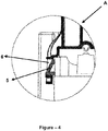
Figure 4 ; is a front sectional view of the detail A ofFigure 1 . - All the parts illustrated in figures are individually assigned a reference numeral and the corresponding terms of these numbers are listed below:
Bottom support (1) Front support (2) Connecting pin (3) Pin housing (4) Snap (5) Snap housing (6) First connection housing (7) Second connection housing (8) - Devices which are used to wash and/or dry the textile products comprise at least one body and at least one drum which is located inside the body and suitable for receiving said textile products. Said drum is supported inside the body by means of at least one framework. The framework supporting the drum generally consists of several pieces. Said framework is desired not only to be produced in a practical and simple way, but also to be durable. For that reason, the present invention provides a durable and reliable framework which is suitable for being used in the washing and/or drying devices and is produced in a simple and practical way.
- The framework according to the present invention, exemplary views of which are illustrated in
figures 1-4 , comprises at least one bottom support (1); at least one front support (2) suitable for being connected to the bottom support (1); at least one (preferably only one) connecting pin (3) which is provided at the front support (2) or the bottom support (1) and is preferably in the form of a cylinder; at least one (preferably only one) pin housing (4) which is provided at the bottom support (2) or the front support (1) (e.g. the one without a connecting pin (3)), is suitable for receiving said connecting pin (3) such that the connecting pin is preferably able to perform rotary motion, and is preferably in the form of a hollow cylinder; at least one snap (5) provided at the front support (2) or the bottom support (1); at least one snap housing (6) which is provided at the bottom support (1) or the front support (2) (e.g. the one without a snap (5)), and suitable for receiving said snap (5) when the bottom support (1) and the front support (2) are connected to each other. - In an exemplary embodiment of the invention, said front support (2) is able to be connected to at least one side of the bottom support (1) at at least one side. In this embodiment, said connecting pin (3) is provided at the corner of a side of the front support (2) from where the front support is connected to the bottom support (1), wherein said connecting pin (3) is perpendicular to said side axis. Said pin housing (4), on the other hand, is provided at the corner of a side of the bottom support (1) from where the bottom support is connected to the front support (2). Yet in a different example, locations of the connecting pin (3) and the pin housing (4) may be vice versa (such that the connecting pin (3) is at the bottom support (1), and the pin housing (4) is at the front support (2)). In both examples, when the connecting pin (3) is received at the pin housing (4) as shown in
figures 2 and3 , the front support (2) is able to perform rotary motion with respect to the bottom support (1). This rotation is performed such that the connection side of the front support (2) approaches to and moves away from the connection side of the bottom support (1). Said snap (5) is preferably provided at a corner of the connection side of the bottom support (1) which is away from the pin housing (4). The snap housing (6) corresponding to the snap (5) is provided at a corner of the connection side of the front support (2) which is away from the connecting pin (3) (locations of the snap (5) and the snap housing (6) may be vice versa, as well). In here, when the front support (2) is moved with respect to the bottom support (1) such that the connection side of the front support (2) approaches to the connection side of the bottom support (1), said snap (5) is received at the snap housing (6). By this way, rotational movement of the front support (2) with respect to the bottom support (1) is prevented by means of the snap (5) and the snap housing (6). As a result, it is enabled that the front support (2) and the bottom support (1) are connected to each other in a quick and reliable way. - In a preferred embodiment of the invention, said framework comprises at least a first connection housing (7) provided at the front support (2), at least a second connection housing (8) provided at the bottom support (1), and at least one connection element (not shown in the figures) fixed to the front support (2) at at least one side, and to the bottom support (1) at at least another side such that it passes through the first connection housing (7) and the second connection housing (8). Said first connection housing (7) and the second connection housing (8) is positioned so as to be at the same horizontal line when the snap (5) is received at the snap housing (6). By this way, the connection element being preferably in the form of a screw passes through the first connection housing (7) and the second connection housing (8) to strengthen the connection between the front support (2) and the bottom support (1).
- The framework according to the present invention enables to perform connection process easily since the connecting pin (3), the pin housing (4), the snap (5) and the snap housing (6) are used to connect the front support (2) and the bottom support (1) each other. Moreover, because of the fact that the front support (2) is prevented from moving at different axis with respect to the bottom support (1) as a result of said connection, a durable and reliable framework is enabled, as well.
Claims (5)
- A framework suitable for being used in washing and/or drying devices and comprising at least one bottom support (1); at least one front support (2) suitable for being connected to the bottom support (1);
characterized by comprising:- at least one connecting pin (3) provided at the front support (2) or the bottom support (1);- at least one pin housing (4) which is provided at the bottom support (1) or the front support (2) and suitable for receiving said connecting pin (3);- at least one snap (5) provided at the front support (2) or the bottom support (1);- at least one snap housing (6) which is provided at the bottom support (1) or the front support (2), and suitable for receiving said snap (5) when the bottom support (1) and the front support (2) are connected to each other. - A framework according to Claim 1, characterized in that said connecting pin (3) is in the form of a cylinder.
- A framework according to Claim 1, characterized in that said pin housing (4) is in the form of a hollow cylinder.
- A framework according to Claim 1, characterized by comprising at least a first connection housing (7) provided at the front support (2), at least a second connection housing (8) provided at the bottom support (1), and at least one connection element fixed to the front support (2) at at least one side, and to the bottom support (1) at at least another side such that it passes through the first connection housing (7) and the second connection housing (8).
- A framework according to Claim 4, characterized in that said connection element is a screw.
Applications Claiming Priority (1)
| Application Number | Priority Date | Filing Date | Title |
|---|---|---|---|
| TR201804258 | 2018-03-26 |
Publications (2)
| Publication Number | Publication Date |
|---|---|
| EP3546636A1 true EP3546636A1 (en) | 2019-10-02 |
| EP3546636B1 EP3546636B1 (en) | 2022-09-14 |
Family
ID=64559435
Family Applications (1)
| Application Number | Title | Priority Date | Filing Date |
|---|---|---|---|
| EP18207688.5A Active EP3546636B1 (en) | 2018-03-26 | 2018-11-22 | A framework for washing and/or drying devices |
Country Status (1)
| Country | Link |
|---|---|
| EP (1) | EP3546636B1 (en) |
Citations (6)
| Publication number | Priority date | Publication date | Assignee | Title |
|---|---|---|---|---|
| DE2840939A1 (en) * | 1978-05-26 | 1979-12-06 | Domar Sa | FRAME AND CASE FOR WASHING MACHINES |
| US20040154909A1 (en) * | 2002-11-29 | 2004-08-12 | Kim Jong Seok | Control panel assembly of washing machine |
| US20060230630A1 (en) | 2005-03-31 | 2006-10-19 | Lg Electronics Inc. | Laundry dryer and impurity entry preventing structure for the same |
| EP1806447A2 (en) * | 2006-01-10 | 2007-07-11 | MIELE & CIE. KG | Casing for a front-loading clothes washing machine |
| DE102013102512A1 (en) * | 2013-03-13 | 2014-09-18 | Miele & Cie. Kg | Housing for household appliances such as tumble dryer, washing machine, dishwasher or the like |
| EP2801652A1 (en) * | 2013-05-07 | 2014-11-12 | Miele & Cie. KG | Housing for a domestic appliance such as a laundry dryer and a method for producing a housing |
-
2018
- 2018-11-22 EP EP18207688.5A patent/EP3546636B1/en active Active
Patent Citations (6)
| Publication number | Priority date | Publication date | Assignee | Title |
|---|---|---|---|---|
| DE2840939A1 (en) * | 1978-05-26 | 1979-12-06 | Domar Sa | FRAME AND CASE FOR WASHING MACHINES |
| US20040154909A1 (en) * | 2002-11-29 | 2004-08-12 | Kim Jong Seok | Control panel assembly of washing machine |
| US20060230630A1 (en) | 2005-03-31 | 2006-10-19 | Lg Electronics Inc. | Laundry dryer and impurity entry preventing structure for the same |
| EP1806447A2 (en) * | 2006-01-10 | 2007-07-11 | MIELE & CIE. KG | Casing for a front-loading clothes washing machine |
| DE102013102512A1 (en) * | 2013-03-13 | 2014-09-18 | Miele & Cie. Kg | Housing for household appliances such as tumble dryer, washing machine, dishwasher or the like |
| EP2801652A1 (en) * | 2013-05-07 | 2014-11-12 | Miele & Cie. KG | Housing for a domestic appliance such as a laundry dryer and a method for producing a housing |
Also Published As
| Publication number | Publication date |
|---|---|
| EP3546636B1 (en) | 2022-09-14 |
Similar Documents
| Publication | Publication Date | Title |
|---|---|---|
| RU2291922C2 (en) | Support for washing machine and cloths drying apparatus | |
| EP2140058B1 (en) | Laundry treating apparatus | |
| US9371608B2 (en) | Laundry treatment apparatus | |
| US9567701B2 (en) | Laundry treating apparatus | |
| EP2891737B1 (en) | Drum type washing machine | |
| US10697102B2 (en) | Laundry treatment apparatus | |
| WO2002090640A1 (en) | Clothes drying machine | |
| JP6870068B2 (en) | Clothes processing equipment | |
| KR101084116B1 (en) | Door of drum washing machine | |
| EP3546636A1 (en) | A framework for washing and/or drying devices | |
| EP2519682B1 (en) | A laundry dryer | |
| RU2425186C2 (en) | Dryer machine for linen | |
| US20150020556A1 (en) | Clothes treatment apparatus | |
| US10590586B2 (en) | Washing machine having an improved coupling structure | |
| US20180148884A1 (en) | Laundry platform accessory | |
| US6807751B2 (en) | Laundry drier | |
| EP4187009A1 (en) | A household appliance comprising a knob | |
| KR101734432B1 (en) | Easy folding clothes dryer | |
| US20040129031A1 (en) | Installation and washing machine for the wet treatment of laundry | |
| ITTO20120039A1 (en) | DISHWASHER MACHINE WITH MOBILE PORT ACESTO DEVICE | |
| CN211368149U (en) | Ironing board capable of being quickly assembled and disassembled and convenient to store | |
| KR101950428B1 (en) | Clothes dryer | |
| CN110924074B (en) | Support for washing equipment | |
| KR200473928Y1 (en) | Furniture-loading clothes | |
| JP3110720U (en) | Shelf mounting bracket for electric washing machine and shelf unit for electric washing machine |
Legal Events
| Date | Code | Title | Description |
|---|---|---|---|
| PUAI | Public reference made under article 153(3) epc to a published international application that has entered the european phase |
Free format text: ORIGINAL CODE: 0009012 |
|
| STAA | Information on the status of an ep patent application or granted ep patent |
Free format text: STATUS: THE APPLICATION HAS BEEN PUBLISHED |
|
| AK | Designated contracting states |
Kind code of ref document: A1 Designated state(s): AL AT BE BG CH CY CZ DE DK EE ES FI FR GB GR HR HU IE IS IT LI LT LU LV MC MK MT NL NO PL PT RO RS SE SI SK SM TR |
|
| AX | Request for extension of the european patent |
Extension state: BA ME |
|
| STAA | Information on the status of an ep patent application or granted ep patent |
Free format text: STATUS: REQUEST FOR EXAMINATION WAS MADE |
|
| 17P | Request for examination filed |
Effective date: 20200331 |
|
| RBV | Designated contracting states (corrected) |
Designated state(s): AL AT BE BG CH CY CZ DE DK EE ES FI FR GB GR HR HU IE IS IT LI LT LU LV MC MK MT NL NO PL PT RO RS SE SI SK SM TR |
|
| GRAP | Despatch of communication of intention to grant a patent |
Free format text: ORIGINAL CODE: EPIDOSNIGR1 |
|
| STAA | Information on the status of an ep patent application or granted ep patent |
Free format text: STATUS: GRANT OF PATENT IS INTENDED |
|
| INTG | Intention to grant announced |
Effective date: 20220425 |
|
| GRAS | Grant fee paid |
Free format text: ORIGINAL CODE: EPIDOSNIGR3 |
|
| GRAA | (expected) grant |
Free format text: ORIGINAL CODE: 0009210 |
|
| STAA | Information on the status of an ep patent application or granted ep patent |
Free format text: STATUS: THE PATENT HAS BEEN GRANTED |
|
| AK | Designated contracting states |
Kind code of ref document: B1 Designated state(s): AL AT BE BG CH CY CZ DE DK EE ES FI FR GB GR HR HU IE IS IT LI LT LU LV MC MK MT NL NO PL PT RO RS SE SI SK SM TR |
|
| REG | Reference to a national code |
Ref country code: GB Ref legal event code: FG4D |
|
| REG | Reference to a national code |
Ref country code: CH Ref legal event code: EP |
|
| REG | Reference to a national code |
Ref country code: DE Ref legal event code: R096 Ref document number: 602018040601 Country of ref document: DE |
|
| REG | Reference to a national code |
Ref country code: IE Ref legal event code: FG4D |
|
| REG | Reference to a national code |
Ref country code: AT Ref legal event code: REF Ref document number: 1518758 Country of ref document: AT Kind code of ref document: T Effective date: 20221015 |
|
| REG | Reference to a national code |
Ref country code: LT Ref legal event code: MG9D |
|
| REG | Reference to a national code |
Ref country code: NL Ref legal event code: MP Effective date: 20220914 |
|
| PG25 | Lapsed in a contracting state [announced via postgrant information from national office to epo] |
Ref country code: SE Free format text: LAPSE BECAUSE OF FAILURE TO SUBMIT A TRANSLATION OF THE DESCRIPTION OR TO PAY THE FEE WITHIN THE PRESCRIBED TIME-LIMIT Effective date: 20220914 Ref country code: RS Free format text: LAPSE BECAUSE OF FAILURE TO SUBMIT A TRANSLATION OF THE DESCRIPTION OR TO PAY THE FEE WITHIN THE PRESCRIBED TIME-LIMIT Effective date: 20220914 Ref country code: NO Free format text: LAPSE BECAUSE OF FAILURE TO SUBMIT A TRANSLATION OF THE DESCRIPTION OR TO PAY THE FEE WITHIN THE PRESCRIBED TIME-LIMIT Effective date: 20221214 Ref country code: LV Free format text: LAPSE BECAUSE OF FAILURE TO SUBMIT A TRANSLATION OF THE DESCRIPTION OR TO PAY THE FEE WITHIN THE PRESCRIBED TIME-LIMIT Effective date: 20220914 Ref country code: LT Free format text: LAPSE BECAUSE OF FAILURE TO SUBMIT A TRANSLATION OF THE DESCRIPTION OR TO PAY THE FEE WITHIN THE PRESCRIBED TIME-LIMIT Effective date: 20220914 Ref country code: FI Free format text: LAPSE BECAUSE OF FAILURE TO SUBMIT A TRANSLATION OF THE DESCRIPTION OR TO PAY THE FEE WITHIN THE PRESCRIBED TIME-LIMIT Effective date: 20220914 |
|
| REG | Reference to a national code |
Ref country code: AT Ref legal event code: MK05 Ref document number: 1518758 Country of ref document: AT Kind code of ref document: T Effective date: 20220914 |
|
| PG25 | Lapsed in a contracting state [announced via postgrant information from national office to epo] |
Ref country code: HR Free format text: LAPSE BECAUSE OF FAILURE TO SUBMIT A TRANSLATION OF THE DESCRIPTION OR TO PAY THE FEE WITHIN THE PRESCRIBED TIME-LIMIT Effective date: 20220914 Ref country code: GR Free format text: LAPSE BECAUSE OF FAILURE TO SUBMIT A TRANSLATION OF THE DESCRIPTION OR TO PAY THE FEE WITHIN THE PRESCRIBED TIME-LIMIT Effective date: 20221215 |
|
| PG25 | Lapsed in a contracting state [announced via postgrant information from national office to epo] |
Ref country code: SM Free format text: LAPSE BECAUSE OF FAILURE TO SUBMIT A TRANSLATION OF THE DESCRIPTION OR TO PAY THE FEE WITHIN THE PRESCRIBED TIME-LIMIT Effective date: 20220914 Ref country code: RO Free format text: LAPSE BECAUSE OF FAILURE TO SUBMIT A TRANSLATION OF THE DESCRIPTION OR TO PAY THE FEE WITHIN THE PRESCRIBED TIME-LIMIT Effective date: 20220914 Ref country code: PT Free format text: LAPSE BECAUSE OF FAILURE TO SUBMIT A TRANSLATION OF THE DESCRIPTION OR TO PAY THE FEE WITHIN THE PRESCRIBED TIME-LIMIT Effective date: 20230116 Ref country code: ES Free format text: LAPSE BECAUSE OF FAILURE TO SUBMIT A TRANSLATION OF THE DESCRIPTION OR TO PAY THE FEE WITHIN THE PRESCRIBED TIME-LIMIT Effective date: 20220914 Ref country code: CZ Free format text: LAPSE BECAUSE OF FAILURE TO SUBMIT A TRANSLATION OF THE DESCRIPTION OR TO PAY THE FEE WITHIN THE PRESCRIBED TIME-LIMIT Effective date: 20220914 Ref country code: AT Free format text: LAPSE BECAUSE OF FAILURE TO SUBMIT A TRANSLATION OF THE DESCRIPTION OR TO PAY THE FEE WITHIN THE PRESCRIBED TIME-LIMIT Effective date: 20220914 |
|
| PG25 | Lapsed in a contracting state [announced via postgrant information from national office to epo] |
Ref country code: SK Free format text: LAPSE BECAUSE OF FAILURE TO SUBMIT A TRANSLATION OF THE DESCRIPTION OR TO PAY THE FEE WITHIN THE PRESCRIBED TIME-LIMIT Effective date: 20220914 Ref country code: PL Free format text: LAPSE BECAUSE OF FAILURE TO SUBMIT A TRANSLATION OF THE DESCRIPTION OR TO PAY THE FEE WITHIN THE PRESCRIBED TIME-LIMIT Effective date: 20220914 Ref country code: IS Free format text: LAPSE BECAUSE OF FAILURE TO SUBMIT A TRANSLATION OF THE DESCRIPTION OR TO PAY THE FEE WITHIN THE PRESCRIBED TIME-LIMIT Effective date: 20230114 Ref country code: EE Free format text: LAPSE BECAUSE OF FAILURE TO SUBMIT A TRANSLATION OF THE DESCRIPTION OR TO PAY THE FEE WITHIN THE PRESCRIBED TIME-LIMIT Effective date: 20220914 |
|
| REG | Reference to a national code |
Ref country code: DE Ref legal event code: R097 Ref document number: 602018040601 Country of ref document: DE |
|
| PG25 | Lapsed in a contracting state [announced via postgrant information from national office to epo] |
Ref country code: NL Free format text: LAPSE BECAUSE OF FAILURE TO SUBMIT A TRANSLATION OF THE DESCRIPTION OR TO PAY THE FEE WITHIN THE PRESCRIBED TIME-LIMIT Effective date: 20220914 Ref country code: MC Free format text: LAPSE BECAUSE OF FAILURE TO SUBMIT A TRANSLATION OF THE DESCRIPTION OR TO PAY THE FEE WITHIN THE PRESCRIBED TIME-LIMIT Effective date: 20220914 Ref country code: AL Free format text: LAPSE BECAUSE OF FAILURE TO SUBMIT A TRANSLATION OF THE DESCRIPTION OR TO PAY THE FEE WITHIN THE PRESCRIBED TIME-LIMIT Effective date: 20220914 |
|
| REG | Reference to a national code |
Ref country code: CH Ref legal event code: PL |
|
| PLBE | No opposition filed within time limit |
Free format text: ORIGINAL CODE: 0009261 |
|
| STAA | Information on the status of an ep patent application or granted ep patent |
Free format text: STATUS: NO OPPOSITION FILED WITHIN TIME LIMIT |
|
| REG | Reference to a national code |
Ref country code: BE Ref legal event code: MM Effective date: 20221130 |
|
| PG25 | Lapsed in a contracting state [announced via postgrant information from national office to epo] |
Ref country code: LI Free format text: LAPSE BECAUSE OF NON-PAYMENT OF DUE FEES Effective date: 20221130 Ref country code: DK Free format text: LAPSE BECAUSE OF FAILURE TO SUBMIT A TRANSLATION OF THE DESCRIPTION OR TO PAY THE FEE WITHIN THE PRESCRIBED TIME-LIMIT Effective date: 20220914 Ref country code: CH Free format text: LAPSE BECAUSE OF NON-PAYMENT OF DUE FEES Effective date: 20221130 |
|
| 26N | No opposition filed |
Effective date: 20230615 |
|
| PG25 | Lapsed in a contracting state [announced via postgrant information from national office to epo] |
Ref country code: SI Free format text: LAPSE BECAUSE OF FAILURE TO SUBMIT A TRANSLATION OF THE DESCRIPTION OR TO PAY THE FEE WITHIN THE PRESCRIBED TIME-LIMIT Effective date: 20220914 Ref country code: LU Free format text: LAPSE BECAUSE OF NON-PAYMENT OF DUE FEES Effective date: 20221122 |
|
| PG25 | Lapsed in a contracting state [announced via postgrant information from national office to epo] |
Ref country code: IE Free format text: LAPSE BECAUSE OF NON-PAYMENT OF DUE FEES Effective date: 20221122 |
|
| PG25 | Lapsed in a contracting state [announced via postgrant information from national office to epo] |
Ref country code: BE Free format text: LAPSE BECAUSE OF NON-PAYMENT OF DUE FEES Effective date: 20221130 |
|
| PG25 | Lapsed in a contracting state [announced via postgrant information from national office to epo] |
Ref country code: HU Free format text: LAPSE BECAUSE OF FAILURE TO SUBMIT A TRANSLATION OF THE DESCRIPTION OR TO PAY THE FEE WITHIN THE PRESCRIBED TIME-LIMIT; INVALID AB INITIO Effective date: 20181122 |
|
| PG25 | Lapsed in a contracting state [announced via postgrant information from national office to epo] |
Ref country code: CY Free format text: LAPSE BECAUSE OF FAILURE TO SUBMIT A TRANSLATION OF THE DESCRIPTION OR TO PAY THE FEE WITHIN THE PRESCRIBED TIME-LIMIT Effective date: 20220914 |
|
| PG25 | Lapsed in a contracting state [announced via postgrant information from national office to epo] |
Ref country code: MK Free format text: LAPSE BECAUSE OF FAILURE TO SUBMIT A TRANSLATION OF THE DESCRIPTION OR TO PAY THE FEE WITHIN THE PRESCRIBED TIME-LIMIT Effective date: 20220914 Ref country code: IT Free format text: LAPSE BECAUSE OF FAILURE TO SUBMIT A TRANSLATION OF THE DESCRIPTION OR TO PAY THE FEE WITHIN THE PRESCRIBED TIME-LIMIT Effective date: 20220914 |
|
| PG25 | Lapsed in a contracting state [announced via postgrant information from national office to epo] |
Ref country code: BG Free format text: LAPSE BECAUSE OF FAILURE TO SUBMIT A TRANSLATION OF THE DESCRIPTION OR TO PAY THE FEE WITHIN THE PRESCRIBED TIME-LIMIT Effective date: 20220914 |
|
| PG25 | Lapsed in a contracting state [announced via postgrant information from national office to epo] |
Ref country code: MT Free format text: LAPSE BECAUSE OF FAILURE TO SUBMIT A TRANSLATION OF THE DESCRIPTION OR TO PAY THE FEE WITHIN THE PRESCRIBED TIME-LIMIT Effective date: 20220914 |
|
| PGFP | Annual fee paid to national office [announced via postgrant information from national office to epo] |
Ref country code: DE Payment date: 20251119 Year of fee payment: 8 |
|
| PGFP | Annual fee paid to national office [announced via postgrant information from national office to epo] |
Ref country code: GB Payment date: 20251121 Year of fee payment: 8 |
|
| PGFP | Annual fee paid to national office [announced via postgrant information from national office to epo] |
Ref country code: FR Payment date: 20251126 Year of fee payment: 8 |
|
| PGFP | Annual fee paid to national office [announced via postgrant information from national office to epo] |
Ref country code: TR Payment date: 20251120 Year of fee payment: 8 |