EP3546374A1 - Cap with sealant flow path - Google Patents
Cap with sealant flow path Download PDFInfo
- Publication number
- EP3546374A1 EP3546374A1 EP19163229.8A EP19163229A EP3546374A1 EP 3546374 A1 EP3546374 A1 EP 3546374A1 EP 19163229 A EP19163229 A EP 19163229A EP 3546374 A1 EP3546374 A1 EP 3546374A1
- Authority
- EP
- European Patent Office
- Prior art keywords
- cap
- base
- fastener
- annular
- skirt
- Prior art date
- Legal status (The legal status is an assumption and is not a legal conclusion. Google has not performed a legal analysis and makes no representation as to the accuracy of the status listed.)
- Granted
Links
Images


Classifications
-
- F—MECHANICAL ENGINEERING; LIGHTING; HEATING; WEAPONS; BLASTING
- F16—ENGINEERING ELEMENTS AND UNITS; GENERAL MEASURES FOR PRODUCING AND MAINTAINING EFFECTIVE FUNCTIONING OF MACHINES OR INSTALLATIONS; THERMAL INSULATION IN GENERAL
- F16B—DEVICES FOR FASTENING OR SECURING CONSTRUCTIONAL ELEMENTS OR MACHINE PARTS TOGETHER, e.g. NAILS, BOLTS, CIRCLIPS, CLAMPS, CLIPS OR WEDGES; JOINTS OR JOINTING
- F16B37/00—Nuts or like thread-engaging members
- F16B37/14—Cap nuts; Nut caps or bolt caps
-
- B—PERFORMING OPERATIONS; TRANSPORTING
- B64—AIRCRAFT; AVIATION; COSMONAUTICS
- B64C—AEROPLANES; HELICOPTERS
- B64C1/00—Fuselages; Constructional features common to fuselages, wings, stabilising surfaces or the like
-
- B—PERFORMING OPERATIONS; TRANSPORTING
- B64—AIRCRAFT; AVIATION; COSMONAUTICS
- B64C—AEROPLANES; HELICOPTERS
- B64C1/00—Fuselages; Constructional features common to fuselages, wings, stabilising surfaces or the like
- B64C1/26—Attaching the wing or tail units or stabilising surfaces
-
- B—PERFORMING OPERATIONS; TRANSPORTING
- B64—AIRCRAFT; AVIATION; COSMONAUTICS
- B64D—EQUIPMENT FOR FITTING IN OR TO AIRCRAFT; FLIGHT SUITS; PARACHUTES; ARRANGEMENT OR MOUNTING OF POWER PLANTS OR PROPULSION TRANSMISSIONS IN AIRCRAFT
- B64D45/00—Aircraft indicators or protectors not otherwise provided for
- B64D45/02—Lightning protectors; Static dischargers
-
- F—MECHANICAL ENGINEERING; LIGHTING; HEATING; WEAPONS; BLASTING
- F16—ENGINEERING ELEMENTS AND UNITS; GENERAL MEASURES FOR PRODUCING AND MAINTAINING EFFECTIVE FUNCTIONING OF MACHINES OR INSTALLATIONS; THERMAL INSULATION IN GENERAL
- F16B—DEVICES FOR FASTENING OR SECURING CONSTRUCTIONAL ELEMENTS OR MACHINE PARTS TOGETHER, e.g. NAILS, BOLTS, CIRCLIPS, CLAMPS, CLIPS OR WEDGES; JOINTS OR JOINTING
- F16B33/00—Features common to bolt and nut
- F16B33/004—Sealing; Insulation
-
- F—MECHANICAL ENGINEERING; LIGHTING; HEATING; WEAPONS; BLASTING
- F16—ENGINEERING ELEMENTS AND UNITS; GENERAL MEASURES FOR PRODUCING AND MAINTAINING EFFECTIVE FUNCTIONING OF MACHINES OR INSTALLATIONS; THERMAL INSULATION IN GENERAL
- F16B—DEVICES FOR FASTENING OR SECURING CONSTRUCTIONAL ELEMENTS OR MACHINE PARTS TOGETHER, e.g. NAILS, BOLTS, CIRCLIPS, CLAMPS, CLIPS OR WEDGES; JOINTS OR JOINTING
- F16B33/00—Features common to bolt and nut
Definitions
- the present invention relates to a cap for forming a sealed cavity around an end of a fastener.
- the present invention relates to a spark containment cap.
- the present invention also relates to a joint, a method of assembling a joint, and an aircraft comprising at least one of the cap and the joint.
- Figure 1 is a side view of part of a fastener assembly passing through a panel 1, which may be a composite or metallic panel.
- the assembly comprises a fastener comprising an externally threaded bolt 2, an internally threaded nut 3, and a washer 4.
- sparking, plasma or out-gassing may occur at the locations indicated by reference 5 in Figure 1 .
- injectable nut caps for example WO 2015/025130 , which are provided over the end of the fastener protruding from the panel.
- Such a nut cap is provided to form a sealed cavity around an end of a fastener.
- An inner cap body is provided that terminates at an inner cap rim which surrounds an opening into a central cavity.
- An annular skirt terminating at a skirt rim provides an annular pocket between the skirt and the inner cap body, in which a curable sealing material is provided. However, uncured sealing material may flow from the pocket.
- a cap for forming a sealed cavity around an end o*f a fastener protruding from a surface of a structure, the cap comprising: a cap body with an annular base terminating at a base rim which surrounds an opening into a central cavity for receiving the end of the fastener and lies in a base rim plane around at least a majority of a circumference of the annular base; an annular skirt providing an annular pocket for receiving a sealant material between the skirt and the annular base, and a biasing configuration configured to positively bias the base rim against the surface of the structure.
- the base rim is urged into a close engagement with the surface of the structure from which the end of the fastener extends. As such, leakage of air and sealant into the central cavity can be minimised.
- the annular base may comprise a cap axis, the biasing configuration being displaceable radially away from the cap axis and being biased radially towards the cap axis upon displacement.
- At least part of the annular base may be configured to distend radially outwardly.
- the annular base may act on the biasing configuration to bias the biasing configuration radially inwardly.
- the biasing configuration may comprise at least one protrusion extending inwardly from the base into the central cavity, wherein the at least one protrusion comprises a cam surface arranged to locate against the fastener, the cam surface being inclined to slope towards the base rim plane away from the base to a free end of the at least one protrusion.
- At least one protrusion may comprise at least two, and optionally at least three, opposing protrusions distributed around the cap body.
- the at least two opposing protrusions may be distributed around an internal face of the annular base, wherein the annular base may have a lobed shape in cross-section such that a radially outwardly bulging lobe extends between each neighbouring pair of protrusions.
- the base of the cap may be used to provide an urging force.
- the cap may be formed in a simple manner.
- the at least one protrusion may comprise a guide element forming the cam surface.
- the at least one protrusion may comprise a rib projecting inwardly from the base, and the guide element may project from the rib.
- the cam surface may be planar.
- the cam surface may be inclined at between 15-60 degrees to the base rim plane.
- the at least one protrusion may be in a fixed relationship with the annular base.
- the at least one protrusion may be proximate to or at the base rim.
- the at least one protrusion may comprise a displacing face configured to abut the fastener when the cap is received over the end of the fastener to urge the at least one protrusion to distend radially outwardly.
- a spark prevention cap for forming a sealed cavity around an end of a fastener, the cap comprising: a cap body with an annular base terminating at a base rim which surrounds an opening into a central cavity for receiving the end of the fastener and lies in a base rim plane around at least a majority of a circumference of the annular base; at least two guide elements distributed around an internal face of the annular base, each guide element extending inwardly into the central cavity from the base; wherein the annular base has a lobed shape in cross-section such that a radially outwardly bulging lobe extends between each neighbouring pair of guide elements.
- Each guide element may be a retention tab.
- Each guide element may comprise a cam surface, the cam surface being inclined to slope towards the base rim plane away from the base to a free end of each guide element.
- the cap may comprise an annular skirt providing an annular pocket for receiving a sealant material between the skirt and the annular base.
- the cap may comprise an inlet hole in the skirt, wherein the inlet hole is in fluid communication with the pocket to permit a flow of sealing material through the skirt via the inlet hole into the pocket; and an outlet in the skirt, wherein the outlet is in fluid communication with the pocket and arranged to enable air to escape the annular pocket through the skirt via the outlet as the sealing material flows from the inlet hole into the pocket.
- the base rim may lay in the base rim plane around the full circumference of the skirt.
- a joint comprising: a structure; an end of a fastener protruding from the structure; and a cap as described above forming a sealed cavity around the end of the fastener, the cap comprising a cured sealing material in the annular pocket which secures the cap to the structure.
- a method of assembling the joint as described above comprising: fitting the cap over the end of the fastener; and injecting sealing material into the annular pocket.
- the aircraft 10 includes a fuselage 11. Two wings 12 extend from the fuselage 11. It will be appreciated that the fuselage 11 and wings 12 may take a variety of different planform shapes and profiles depending on the particular application. Fuel tanks 13 are formed in the fuselage 11 and wings 12. One such fuel tank 13 is shown schematically in Figure 2 . The fuel tanks 13 are formed by a structure or structures forming part of the aircraft 10.
- FIGs 3 to 7 show a joint 100 in stages of installation.
- the joint 100 is shown assembled in Figure 3 .
- the joint 100 comprises a structure 110 such as an aircraft skin panel.
- the structure 110 has a planar surface 111.
- a fastener 120 extends through the structure 110.
- the structure 110 in this embodiment is a composite aircraft structural component, but may be a hybrid composite-metallic or other component.
- the fastener 120 comprises a first fastening member 122 and a second fastening member 123.
- the first and second fastening members 122, 123 are engageable with each other.
- the second fastening member 123 comprises an axially extending shaft 123a protruding from the structure 110.
- the first fastening member 122 comprises a nut 122a screwed onto the shaft 123a and a washer 124 between the nut 122a and the structure 110.
- the nut 122a is threadingly engageable on the shaft 123a.
- the fastener 120 defines a longitudinal axis.
- the washer 124 is stepped.
- the washer 124 defines a step 125 of the fastener 120.
- the step 125 is formed by a diametrically recessed section 126 in an outer side of the washer 124.
- the step 125 faces a structure contact face 127 of the washer 124.
- the washer 124 comprises first and second washer parts in which the second washer part has a smaller diameter than the first washer part.
- the step 125 may be formed by a groove in the washer 124 (not shown).
- the step is defined by the washer having a smaller outer diameter than the nut.
- the step is formed in the nut.
- a cap 200 encloses the end 121 of the fastener 120 and will be described in detail with reference to Figures 3 to 10 .
- the cap 200 has a cap body 201 with a domed outboard (upper) part 202 and a substantially cylindrical base 210.
- the base 210 is annular.
- the base 210 terminates at a rim 211 which surrounds an opening 212 into a central cavity 130.
- the rim 211 lies in a plane 214 so it can intimately engage with the planar surface 111 of the structure 110 around its full circumference when the cap 200 is fitted over the end 121 of the fastener 120 as shown.
- An annular skirt 220 extends from an outboard (upper) end 221 where it meets the cap body 210 to an inboard (lower) skirt rim 222.
- the skirt has a flared elliptical outboard (upper) part 223 which extends away from the cap body 210, and a substantially cylindrical inboard (lower) part 224 which extends parallel with a cap axis 230.
- the skirt rim 222 represents the inboard (lower) extent of the skirt 220.
- An annular pocket 240 is provided between the skirt 220 and the annular base 210.
- the pocket 240 extends from a closed outboard end 241 at the outboard end 221 of the skirt 220, to an open inboard end 242 at the skirt rim 222. Due to the flared shape of the outboard part 223 of the skirt 220, the pocket 240 has a radial width which increases as it extends from its outboard end 241 to its inboard end 242.
- the skirt 220 has a tubular projection 250 which projects outwardly from the skirt and provides an injection channel leading to a circular inlet hole 251.
- the tubular projection 250 is arranged to interconnect with a nozzle of a sealing material injection device (not shown) to provide a flow of sealing material through the skirt 220 via the inlet hole 251 into the pocket 240. In this case they are interconnected by receiving the projection 250 within the sealing material injection device nozzle, although the opposite arrangement is also possible.
- the skirt 220 also has an outlet 270 on an opposite side of the cap axis 230 to the inlet hole 251.
- the skirt 220 terminates in the skirt rim 222 which surrounds the pocket 240 and lies in a plane around a majority of its circumference except where it is formed with an outlet recess 271 shown most clearly in Figure 5 .
- the outlet recess 271 extends around about 1/6th of the circumference of the cap.
- the outlet 270 is in fluid communication with the pocket 240 and is arranged to enable air to escape the pocket 240 through the skirt via the outlet 270 as the sealing material flows from the inlet hole 251 into the pocket 240.
- the cap body 201 is formed with three protrusions 261.
- the protrusions 261 project inwardly into the central cavity 130.
- the protrusions 261 protrude from an inner surface 213 of the base 210.
- Each protrusion comprises a guide element 260 formed as a tooth.
- Each protrusion 261 acts as a retention tab.
- the retention tabs act to retain the cap 200 on the end of the fastener 120.
- the retention tab acts to guide and retain the cap against the surface 111 of the structure 120.
- Each guide element 260 projects radially inwardly.
- the guide elements 260 are formed at the lower, inboard, end of the cap body 201.
- the guide elements 260 are proximate the base rim 211.
- the cap 200 is formed with three guide elements 260, however the number of guide elements may differ.
- an alternative cap 200 is shown with five guide elements 260.
- the guide elements 260 are dispersed equidistantly around the base 210.
- Each guide element 260 is on a rib 215.
- the ribs 215 extend axially (refer in particular to Figure 5 ) and project inwardly into the central cavity 130.
- the ribs 215 protrude from the inner surface 213 of the base 210.
- the ribs 215 abut the cylindrical outer faces of the washer 124 as an interference fit, when the fastener 120 is received in the cap 200.
- the guide elements 260 protrude from the ribs 215.
- one or more of the guide elements 260 protrudes from the inner surface 213 and the ribs 215 are omitted.
- Each guide element 260 has a fastener locating face 262.
- the locating face 262 acts as a cam surface.
- the locating face 262 is configured to abut against the step 125.
- the locating face 262 is inclined to slope towards the base rim plane 214.
- the locating face 262 extends in an inboard direction from the base 210 to a free end 263 of the guide element 260.
- the cam surface is inclined at between 15-60 degrees to the base rim plane 214.
- each guide element 260 is angled with respect to the cap axis 230.
- the locating faces 262 form closed faces, that is they face into the outboard (upper) end of the cavity 130.
- the locating face 262 of each guide element 260 acting as cam surfaces, are inclined downwardly towards the inboard (lower) end.
- the locating faces 262 are inclined by the same angle with the base rim plane 214.
- the locating faces 262 converge inwardly towards the cap axis 230.
- Each of the locating faces 262 is planar.
- the locating faces 262 extend from the ribs 215, that is away from the base 210.
- the locating faces 262 each provide a contact region at which the guide elements 260 can contact the fastener.
- the protrusions 261 oppose each other in the cavity 130. That is, at least two protrusions 261 are dispersed at greater than 90 degrees to each other. With three evenly distributed protrusions, the protrusions 261 are disposed at 120 degrees to each other, for example.
- Each guide element 260 has an open face 264.
- the open face 264 faces the base rim plane 214.
- the open face 264 is exposed to the opening 212 into a central cavity 130.
- the open face 264 extends from the base rim 211.
- the open face 264 is set back from the base rim 211.
- the open face 264 is inclined to slope away from the base rim plane 214.
- the open face 264 extends in an outboard direction from the cap body to a free end 263 of the guide element 260.
- the locating face 262 and the open face 264 of each guide element 260 converge towards the open end 263.
- the guide element 260 has a substantially triangular profile.
- the distance between the base rim plane 214 and the locating face 262, that is the lower end of the locating face 262, is smaller than the height of the step 125.
- the height of the step 125 corresponds to the distance between the step 125 and the structure contact face 127 of the washer 124.
- the distance between the base rim plane 214 and the upper end of the locating face 262 is greater than the height of the step 125.
- the annular base 210 of the cap body 210 has a tri-lobed shape in cross-section prior to assembly onto the fastener end 121 (the size of the lobes may differ).
- the number of lobes may vary, and so the annular base 210 of the cap body 210 may have a dual-lobed or other multi-lobed shape.
- the tri-lobed cross-sectional shape extends from the base rim 211 of the annular base 210 to a location substantially in line with (or in the vicinity of) the junction between the skirt 220 and the annular base 210.
- the cross-sectional shape of the cap body 201 between this location and the upper domed part 202 changes to provide a continuous blending from the tri-lobed shape to a substantially circular shape.
- the annular base 210 has the three protrusions 261 which extend radially inwardly from three evenly spaced positions around the annular base 210.
- the guide elements 260 provide the cam surface 262 to contact the fastener 120, and the tri-lobed shape is such that a radially outwardly extending lobe 265 extends between each neighbouring pair of protrusions 261.
- the invention extends to embodiments with more than three guide elements 260 and lobes, and especially to embodiments with four, five, six or seven guide elements and lobes.
- annular may have a circular cross-section.
- annular features will have a non-circular cross-sectional shape.
- annular is used herein to refer to a feature (for instance a rim, shoulder, protrusion or recess) which runs round a circumference of the cap assembly regardless of the shape of that circumference.
- the lobed shape of the base 210 enables the base 210 to deform so that it has a substantially cylindrical shape as a result of its installation on the fastener end 121.
- the base 210 is installed on the fastener end 121 so that the locating face 262 of each guide element 260 contact the step 125 of the fastener 120. As shown in the figures, the locating face 262 contacts an edge of the step 125. However, it will be understood that the step may be angled relative to the longitudinal axis of the fastener 120 so that the locating face 162 of each guide element 260 locates against a face of the step 125.
- the circumference of the washer 124 forming the step 125, defining a contact region, is located radially further outwardly than the free end 263 of each guide element 260. Therefore, the protrusions 261 must be urged radially outwardly to achieve installation.
- the base 210 is deformable such that the protrusions 261 are displaceable radially away from the cap axis 230. Upon displacement, the protrusions 261 are biased radially towards the cap axis 230.
- the guide elements 260 therefore distend radially outwardly.
- the open face 264 contacts the fastener 120 and urges the guide elements 260 to distend outwardly.
- the angle of the open face 264 relative to the cap axis 230 causes an outward bias, and the base 210 deforms.
- the guide elements 260 at their free end 263 slide along the fastener 120, until the step 125 is reached.
- the base 210 deforms so that the lobes become shallower, i.e. less curved, to the extent that the base 210 becomes substantially cylindrical, that is less lobed.
- This change in shape provides a radially inward bias between the guide elements 260 and the fastener 120.
- the inward bias of the deformed base 210 causes the guide elements 260 to distend inwardly.
- the cam surface of the guide elements 260 is urged to slide along the edge of the step 125.
- the radially inward distention provides a longitudinal bias to the cap 200 along the cap axis 230. That is, the cap 200 is biased to move in an inboard direction along the cap axis 230, that is towards the surface 111 of the structure 110. The cap 200 is therefore urged into a positive abutment with the structure 110.
- the base rim 211 is biased into a positive engagement with the surface 111.
- the expected deformation of the base 210 when the dimensions of the fastener 120 are at their nominal dimensions For example, if the height of the step 125 is greater than the nominal dimension, or the diameter of the washer 124 is smaller than the nominal dimension (e.g. because of manufacturing tolerances) then the base 210 may remain lobe shaped after installation, but with shallower lobes than before installation.
- the base 210 may adopt an inverse lobed shape, in which the maximum extent of each lobe coincides with the protrusions 261 (that is, the lobes are formed at the protrusions 261 rather than between them). In each of these cases the deformation provides a radial biasing action on the guide elements 260.
- the protrusions 261 are integrally formed with the base 210. That is, the protrusions 261 are in a fixed relationship with the annular base 210. In the presently described embodiments, the inwardly radial bias on the protrusions 261 is provided by the lobed arrangement of the base, alternative configurations are possible. For example, alternatively or additionally the protrusions are pivotally mounted and/or the protrusions themselves are resilient.
- One of the guide elements 260 is disposed adjacent to the inlet hole 251. By providing the inlet hole 251 with the adjacent guide element 260 it is possible to help restrict movement of the cap 200 away from the structure surface 111.
- a suitable material is a nylon material, such as Nylon PA66 or Nylon PA12.
- a suitable sealant material is a polythioether sealant such as PPG PR-2001B2 or a polysulphide sealant such as Naftoseal (R) MC238B, MC238A, or MC780 available from Chemetall Group.
- the cap is retained on the fastener 120 and the base rim 211 is urged into engagement with the surface 111.
- Sealing material is injected into the pocket 240.
- the sealing material flows from the inlet hole 251 into the pocket 240.
- the pocket 240 is full, the pressure in the pocket 240 increases until it forces sealing material to escape the pocket 240 through the skirt 220 via the outlet 270.
- the outlet includes an outlet hole formed through the skirt 220. As the pressure is applied by the sealing material, the cap 200 is urged upwardly.
- the biasing of the protrusions 261 against the step 125 causes a counteraction to the pressure applied by the sealing material to maintain the intimate engagement of the base rim 211 against the surface and prevent any gap being formed between the base 210 and the surface 111. As such, leakage into the inner cavity 130 is prevented.
- the sealing material is then allowed to cure, leaving a cured sealing material 140 (shown in Figure 3 ) in the pocket 240 which secures the cap 200 to the structure 110 and forms a seal around the cavity 130.
- This seal prevents the ingress of water or other contaminants into the cavity 130, and also prevents plasma or other out-gassing products from exiting the cavity 130 in the event of a lightning strike.
- Cured sealing material 140 also fills the injection channel, the inlet hole 251 and the outlet 270.
- the base rim 211 lies in the plane 214.
- the base rim 211 lying in the base rim plane 214 helps to ensure that the base rim 211 is able to intimately engage with the planar surface 111 of the structure 110 around its full circumference when the cap 200 is fitted over the end 121 of the fastener 120 and the biasing configuration of the cap 200 acts on the fastener 120 to positively bias the base rim 211 against the surface 111 of the structure 110.
- the skirt rim 222 lies in a plane 225.
- the skirt rim plane 225 is not coplanar with the base rim plane 214.
- the skirt rim 222 of the skirt 220 is spaced from the base rim plane around its full circumference. As such, there is an offset from the base rim plane 214. The offset defines a gap between the skirt rim 222 and the base rim plane 214.
- the length of the skirt 220 is uniform around the circumference of the skirt 220 except for the recess 271.
- the skirt rim 222 lies in the skirt rim plane 225 around the full circumference of the skirt 220, except for the recess 271.
- the skirt rim plane 222 lies parallel to the base rim plane 214.
- the offset, represented by dimension Y in Figure 4 , of the skirt rim 222 from the base rim plane 214 around at least the majority of the circumference of the skirt 220 is in the range of 0.05mm and 0.35mm. It will be understood that the offset may be determined based on the viscosity of the sealant material to be used with the cap 200.
- the rim 211 lies in its plane so it can intimately engage with the planar surface 111 of the structure 110 around its full circumference. This helps prevent leakage of air and sealant into the inner cavity 130.
- the offset Y of the skirt rim 122 from the plane of the base rim 211 helps to ensure that the skirt 120 does not come into contact with the planar surface 111 of the structure 110.
- the cap may be formed with no offset.
- the skirt rim lies on the base rim plane.
- at least of the skirt and the skirt rim may be formed from a flexible material.
- the skirt and the skirt rim formed from a flexible material extends through the base rim plane.
- the cap is formed from a one-piece cap member, it will be understood that alternative configurations are possible.
- the cap is formed from a two-piece cap member in which the annular pocket is defined between an inner cap member forming the annular base and an outer cap member forming the skirt rim.
- the form and function are generally similar, with the arrangement of the biasing configuration being applicable to such an embodiment.
Landscapes
- Engineering & Computer Science (AREA)
- General Engineering & Computer Science (AREA)
- Mechanical Engineering (AREA)
- Aviation & Aerospace Engineering (AREA)
- Closures For Containers (AREA)
Abstract
Description
- The present invention relates to a cap for forming a sealed cavity around an end of a fastener. In particular, but not exclusively, the present invention relates to a spark containment cap. The present invention also relates to a joint, a method of assembling a joint, and an aircraft comprising at least one of the cap and the joint.
- Large passenger aircraft are typically struck by lightning once or twice a year, each lightning bolt striking with up to 200,000 amps of electrical current that seeks the path of least electrical resistance. Many modern passenger aircraft have exterior surfaces made from composite materials which have a very high electrical resistance. There is therefore a high probability of lightening attachment at any of the many metallic fasteners in the exterior surface, which have a much lower electrical resistance. In the wing, some of these fasteners pass through the outer wing skin into the fuel tank.
-
Figure 1 is a side view of part of a fastener assembly passing through a panel 1, which may be a composite or metallic panel. The assembly comprises a fastener comprising an externally threadedbolt 2, an internally threadednut 3, and awasher 4. In the event of a lightning strike hitting the panel 1 and attaching to the fastener, sparking, plasma or out-gassing may occur at the locations indicated byreference 5 inFigure 1 . - It is known to provide injectable nut caps, for example
WO 2015/025130 , which are provided over the end of the fastener protruding from the panel. Such a nut cap is provided to form a sealed cavity around an end of a fastener. An inner cap body is provided that terminates at an inner cap rim which surrounds an opening into a central cavity. An annular skirt terminating at a skirt rim provides an annular pocket between the skirt and the inner cap body, in which a curable sealing material is provided. However, uncured sealing material may flow from the pocket. - According to an aspect of the invention, there is provided a cap for forming a sealed cavity around an end o*f a fastener protruding from a surface of a structure, the cap comprising: a cap body with an annular base terminating at a base rim which surrounds an opening into a central cavity for receiving the end of the fastener and lies in a base rim plane around at least a majority of a circumference of the annular base; an annular skirt providing an annular pocket for receiving a sealant material between the skirt and the annular base, and a biasing configuration configured to positively bias the base rim against the surface of the structure.
- With this arrangement, the base rim is urged into a close engagement with the surface of the structure from which the end of the fastener extends. As such, leakage of air and sealant into the central cavity can be minimised.
- The annular base may comprise a cap axis, the biasing configuration being displaceable radially away from the cap axis and being biased radially towards the cap axis upon displacement.
- As such, it is possible to provide a biasing force to aid positive engagement of the base rim with the surface prior to a sealant being received by the cap.
- At least part of the annular base may be configured to distend radially outwardly.
- The annular base may act on the biasing configuration to bias the biasing configuration radially inwardly.
- The biasing configuration may comprise at least one protrusion extending inwardly from the base into the central cavity, wherein the at least one protrusion comprises a cam surface arranged to locate against the fastener, the cam surface being inclined to slope towards the base rim plane away from the base to a free end of the at least one protrusion.
- With such an arrangement it is possible to use the protrusions to bias the base rim against the surface.
- At least one protrusion may comprise at least two, and optionally at least three, opposing protrusions distributed around the cap body.
- The at least two opposing protrusions may be distributed around an internal face of the annular base, wherein the annular base may have a lobed shape in cross-section such that a radially outwardly bulging lobe extends between each neighbouring pair of protrusions.
- As such, the base of the cap may be used to provide an urging force. The cap may be formed in a simple manner.
- The at least one protrusion may comprise a guide element forming the cam surface.
- The at least one protrusion may comprise a rib projecting inwardly from the base, and the guide element may project from the rib.
- The cam surface may be planar.
- The cam surface may be inclined at between 15-60 degrees to the base rim plane.
- The at least one protrusion may be in a fixed relationship with the annular base.
- The at least one protrusion may be proximate to or at the base rim.
- The at least one protrusion may comprise a displacing face configured to abut the fastener when the cap is received over the end of the fastener to urge the at least one protrusion to distend radially outwardly.
- According to a further aspect of the invention, there is provided a spark prevention cap for forming a sealed cavity around an end of a fastener, the cap comprising: a cap body with an annular base terminating at a base rim which surrounds an opening into a central cavity for receiving the end of the fastener and lies in a base rim plane around at least a majority of a circumference of the annular base; at least two guide elements distributed around an internal face of the annular base, each guide element extending inwardly into the central cavity from the base; wherein the annular base has a lobed shape in cross-section such that a radially outwardly bulging lobe extends between each neighbouring pair of guide elements.
- Each guide element may be a retention tab.
- With such a configuration, it is possible to simply provide a biasing force to the guide elements to ensure that the guide elements correctly engage with the fastener and restrict removal of the cap from the end of the fastener.
- Each guide element may comprise a cam surface, the cam surface being inclined to slope towards the base rim plane away from the base to a free end of each guide element.
- The cap may comprise an annular skirt providing an annular pocket for receiving a sealant material between the skirt and the annular base.
- The cap may comprise an inlet hole in the skirt, wherein the inlet hole is in fluid communication with the pocket to permit a flow of sealing material through the skirt via the inlet hole into the pocket; and an outlet in the skirt, wherein the outlet is in fluid communication with the pocket and arranged to enable air to escape the annular pocket through the skirt via the outlet as the sealing material flows from the inlet hole into the pocket.
- The base rim may lay in the base rim plane around the full circumference of the skirt.
- According to a further aspect of the invention, there is provided a joint comprising: a structure; an end of a fastener protruding from the structure; and a cap as described above forming a sealed cavity around the end of the fastener, the cap comprising a cured sealing material in the annular pocket which secures the cap to the structure.
- According to a further aspect of the invention, there is provided a method of assembling the joint as described above, the method comprising: fitting the cap over the end of the fastener; and injecting sealing material into the annular pocket.
- Embodiments of the invention will now be described with reference to the accompanying drawings, in which:
-
Figure 1 shows a side view of part of a prior art fastener assembly protruding from a structure; -
Figure 2 shows a perspective view of an aircraft; -
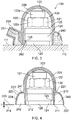
Figure 3 shows a partial cross-sectional front view of a joint comprising a fastener and a cap following injection with a sealant; -
Figure 4 shows a partial cross-sectional side view of the joint ofFigure 3 comprising the fastener and the cap prior to injection with a sealant; -
Figure 5 shows a cross-sectional front view of the cap ofFigures 3 and 4 ; -
Figure 6 shows a side view of the cap ofFigures 3-5 ; -
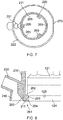
Figure 7 shows a plan view from below of the cap ofFigure 6 ; -
Figure 8 shows a partial cross-sectional view of part of the joint ofFigure 4 ; -
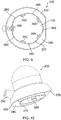
Figure 9 shows a plan view from below of another cap; and -
Figure 10 shows a perspective view of the cap ofFigure 3 . - An
aircraft 10 is shown inFigure 2 . Theaircraft 10 includes afuselage 11. Twowings 12 extend from thefuselage 11. It will be appreciated that thefuselage 11 andwings 12 may take a variety of different planform shapes and profiles depending on the particular application.Fuel tanks 13 are formed in thefuselage 11 andwings 12. Onesuch fuel tank 13 is shown schematically inFigure 2 . Thefuel tanks 13 are formed by a structure or structures forming part of theaircraft 10. -
Figures 3 to 7 show a joint 100 in stages of installation. The joint 100 is shown assembled inFigure 3 . The joint 100 comprises astructure 110 such as an aircraft skin panel. Thestructure 110 has aplanar surface 111. Afastener 120 extends through thestructure 110. Thestructure 110 in this embodiment is a composite aircraft structural component, but may be a hybrid composite-metallic or other component. - An
end 121 of thefastener 120 protrudes from thestructure 110. Thefastener 120 comprises afirst fastening member 122 and asecond fastening member 123. The first andsecond fastening members - The
second fastening member 123 comprises anaxially extending shaft 123a protruding from thestructure 110. Thefirst fastening member 122 comprises anut 122a screwed onto theshaft 123a and awasher 124 between thenut 122a and thestructure 110. Thenut 122a is threadingly engageable on theshaft 123a. Thefastener 120 defines a longitudinal axis. - The
washer 124 is stepped. Thewasher 124 defines astep 125 of thefastener 120. In the Figures thestep 125 is formed by a diametrically recessedsection 126 in an outer side of thewasher 124. Thestep 125 faces a structure contact face 127 of thewasher 124. In an alternative embodiment, thewasher 124 comprises first and second washer parts in which the second washer part has a smaller diameter than the first washer part. Thestep 125 may be formed by a groove in the washer 124 (not shown). In embodiments, the step is defined by the washer having a smaller outer diameter than the nut. In embodiments, the step is formed in the nut. - A
cap 200 encloses theend 121 of thefastener 120 and will be described in detail with reference toFigures 3 to 10 . Thecap 200 has acap body 201 with a domed outboard (upper)part 202 and a substantiallycylindrical base 210. Thebase 210 is annular. Thebase 210 terminates at arim 211 which surrounds anopening 212 into acentral cavity 130. Therim 211 lies in aplane 214 so it can intimately engage with theplanar surface 111 of thestructure 110 around its full circumference when thecap 200 is fitted over theend 121 of thefastener 120 as shown. - An
annular skirt 220 extends from an outboard (upper) end 221 where it meets thecap body 210 to an inboard (lower)skirt rim 222. The skirt has a flared elliptical outboard (upper)part 223 which extends away from thecap body 210, and a substantially cylindrical inboard (lower)part 224 which extends parallel with acap axis 230. Theskirt rim 222 represents the inboard (lower) extent of theskirt 220. - An
annular pocket 240 is provided between theskirt 220 and theannular base 210. Thepocket 240 extends from a closedoutboard end 241 at theoutboard end 221 of theskirt 220, to an openinboard end 242 at theskirt rim 222. Due to the flared shape of theoutboard part 223 of theskirt 220, thepocket 240 has a radial width which increases as it extends from itsoutboard end 241 to itsinboard end 242. - The
skirt 220 has atubular projection 250 which projects outwardly from the skirt and provides an injection channel leading to acircular inlet hole 251. Thetubular projection 250 is arranged to interconnect with a nozzle of a sealing material injection device (not shown) to provide a flow of sealing material through theskirt 220 via theinlet hole 251 into thepocket 240. In this case they are interconnected by receiving theprojection 250 within the sealing material injection device nozzle, although the opposite arrangement is also possible. Theskirt 220 also has anoutlet 270 on an opposite side of thecap axis 230 to theinlet hole 251. Theskirt 220 terminates in theskirt rim 222 which surrounds thepocket 240 and lies in a plane around a majority of its circumference except where it is formed with anoutlet recess 271 shown most clearly inFigure 5 . Theoutlet recess 271 extends around about 1/6th of the circumference of the cap. - The
outlet 270 is in fluid communication with thepocket 240 and is arranged to enable air to escape thepocket 240 through the skirt via theoutlet 270 as the sealing material flows from theinlet hole 251 into thepocket 240. - The
cap body 201 is formed with threeprotrusions 261. Theprotrusions 261 project inwardly into thecentral cavity 130. Theprotrusions 261 protrude from aninner surface 213 of thebase 210. Each protrusion comprises aguide element 260 formed as a tooth. Eachprotrusion 261 acts as a retention tab. The retention tabs act to retain thecap 200 on the end of thefastener 120. The retention tab acts to guide and retain the cap against thesurface 111 of thestructure 120. Eachguide element 260 projects radially inwardly. Theguide elements 260 are formed at the lower, inboard, end of thecap body 201. Theguide elements 260 are proximate thebase rim 211. In the present embodiment thecap 200 is formed with threeguide elements 260, however the number of guide elements may differ. For example, inFigure 9 analternative cap 200 is shown with fiveguide elements 260. Theguide elements 260 are dispersed equidistantly around thebase 210. - Each
guide element 260 is on arib 215. Theribs 215 extend axially (refer in particular toFigure 5 ) and project inwardly into thecentral cavity 130. Theribs 215 protrude from theinner surface 213 of thebase 210. In embodiments, theribs 215 abut the cylindrical outer faces of thewasher 124 as an interference fit, when thefastener 120 is received in thecap 200. Theguide elements 260 protrude from theribs 215. Alternatively, or additionally, one or more of theguide elements 260 protrudes from theinner surface 213 and theribs 215 are omitted. - Each
guide element 260 has afastener locating face 262. The locatingface 262 acts as a cam surface. The locatingface 262 is configured to abut against thestep 125. The locatingface 262 is inclined to slope towards thebase rim plane 214. The locatingface 262 extends in an inboard direction from the base 210 to afree end 263 of theguide element 260. The cam surface is inclined at between 15-60 degrees to thebase rim plane 214. - The locating
face 262 of eachguide element 260 is angled with respect to thecap axis 230. The locating faces 262 form closed faces, that is they face into the outboard (upper) end of thecavity 130. The locatingface 262 of eachguide element 260, acting as cam surfaces, are inclined downwardly towards the inboard (lower) end. The locating faces 262 are inclined by the same angle with thebase rim plane 214. The locating faces 262 converge inwardly towards thecap axis 230. Each of the locating faces 262 is planar. The locating faces 262 extend from theribs 215, that is away from thebase 210. The locating faces 262 each provide a contact region at which theguide elements 260 can contact the fastener. - The
protrusions 261 oppose each other in thecavity 130. That is, at least twoprotrusions 261 are dispersed at greater than 90 degrees to each other. With three evenly distributed protrusions, theprotrusions 261 are disposed at 120 degrees to each other, for example. - Each
guide element 260 has anopen face 264. Theopen face 264 faces thebase rim plane 214. Theopen face 264 is exposed to theopening 212 into acentral cavity 130. Theopen face 264 extends from thebase rim 211. In embodiments, theopen face 264 is set back from thebase rim 211. Theopen face 264 is inclined to slope away from thebase rim plane 214. Theopen face 264 extends in an outboard direction from the cap body to afree end 263 of theguide element 260. The locatingface 262 and theopen face 264 of eachguide element 260 converge towards theopen end 263. Theguide element 260 has a substantially triangular profile. - The distance between the
base rim plane 214 and the locatingface 262, that is the lower end of the locatingface 262, is smaller than the height of thestep 125. The height of thestep 125 corresponds to the distance between thestep 125 and the structure contact face 127 of thewasher 124. The distance between thebase rim plane 214 and the upper end of the locatingface 262 is greater than the height of thestep 125. - As shown in
Figure 7 , theannular base 210 of thecap body 210 has a tri-lobed shape in cross-section prior to assembly onto the fastener end 121 (the size of the lobes may differ). The number of lobes may vary, and so theannular base 210 of thecap body 210 may have a dual-lobed or other multi-lobed shape. - The tri-lobed cross-sectional shape extends from the
base rim 211 of theannular base 210 to a location substantially in line with (or in the vicinity of) the junction between theskirt 220 and theannular base 210. The cross-sectional shape of thecap body 201 between this location and the upperdomed part 202 changes to provide a continuous blending from the tri-lobed shape to a substantially circular shape. Theannular base 210 has the threeprotrusions 261 which extend radially inwardly from three evenly spaced positions around theannular base 210. Theguide elements 260 provide thecam surface 262 to contact thefastener 120, and the tri-lobed shape is such that a radially outwardly extendinglobe 265 extends between each neighbouring pair ofprotrusions 261. Although there are threeguide elements 260, and threelobes 265, in this embodiment, the invention extends to embodiments with more than threeguide elements 260 and lobes, and especially to embodiments with four, five, six or seven guide elements and lobes. - Where various features are described as being annular, these parts may have a circular cross-section. However, in the case of a non-circular cap assembly then these annular features will have a non-circular cross-sectional shape. The term "annular" is used herein to refer to a feature (for instance a rim, shoulder, protrusion or recess) which runs round a circumference of the cap assembly regardless of the shape of that circumference.
- The lobed shape of the
base 210 enables the base 210 to deform so that it has a substantially cylindrical shape as a result of its installation on thefastener end 121. Thebase 210 is installed on thefastener end 121 so that the locatingface 262 of eachguide element 260 contact thestep 125 of thefastener 120. As shown in the figures, the locatingface 262 contacts an edge of thestep 125. However, it will be understood that the step may be angled relative to the longitudinal axis of thefastener 120 so that the locating face 162 of eachguide element 260 locates against a face of thestep 125. - Prior to installation (
Figure 7 ), the circumference of thewasher 124 forming thestep 125, defining a contact region, is located radially further outwardly than thefree end 263 of eachguide element 260. Therefore, theprotrusions 261 must be urged radially outwardly to achieve installation. Thebase 210 is deformable such that theprotrusions 261 are displaceable radially away from thecap axis 230. Upon displacement, theprotrusions 261 are biased radially towards thecap axis 230. Theguide elements 260 therefore distend radially outwardly. Upon insertion of thefastener 120 into thecap 200, theopen face 264 contacts thefastener 120 and urges theguide elements 260 to distend outwardly. The angle of theopen face 264 relative to thecap axis 230 causes an outward bias, and thebase 210 deforms. Theguide elements 260 at theirfree end 263 slide along thefastener 120, until thestep 125 is reached. - As a result of the outward distention of the
guide elements 260, thebase 210 deforms so that the lobes become shallower, i.e. less curved, to the extent that thebase 210 becomes substantially cylindrical, that is less lobed. This change in shape provides a radially inward bias between theguide elements 260 and thefastener 120. When theguide elements 260 overlap thestep 250, the inward bias of thedeformed base 210 causes theguide elements 260 to distend inwardly. The cam surface of theguide elements 260 is urged to slide along the edge of thestep 125. As a result of the incline of the cam surfaces relative to thebase rim plane 214, the radially inward distention provides a longitudinal bias to thecap 200 along thecap axis 230. That is, thecap 200 is biased to move in an inboard direction along thecap axis 230, that is towards thesurface 111 of thestructure 110. Thecap 200 is therefore urged into a positive abutment with thestructure 110. Thebase rim 211 is biased into a positive engagement with thesurface 111. By providing a linear bias against thesurface 111 of thestructure 111, leakage between the base 210 and thesurface 111 is further restricted or prevented. The downward bias acts against an upward force applied on thecap 200 during injection and curing of sealant material into theannular pocket 240. - It will be understood that in the embodiment described herein, the expected deformation of the base 210 when the dimensions of the
fastener 120 are at their nominal dimensions. For example, if the height of thestep 125 is greater than the nominal dimension, or the diameter of thewasher 124 is smaller than the nominal dimension (e.g. because of manufacturing tolerances) then the base 210 may remain lobe shaped after installation, but with shallower lobes than before installation. On the other hand, if the height of thestep 125 is smaller than the nominal dimension, or the diameter of thewasher 124 is greater than the nominal dimension then the base 210 may adopt an inverse lobed shape, in which the maximum extent of each lobe coincides with the protrusions 261 (that is, the lobes are formed at theprotrusions 261 rather than between them). In each of these cases the deformation provides a radial biasing action on theguide elements 260. - The
protrusions 261 are integrally formed with thebase 210. That is, theprotrusions 261 are in a fixed relationship with theannular base 210. In the presently described embodiments, the inwardly radial bias on theprotrusions 261 is provided by the lobed arrangement of the base, alternative configurations are possible. For example, alternatively or additionally the protrusions are pivotally mounted and/or the protrusions themselves are resilient. - One of the
guide elements 260 is disposed adjacent to theinlet hole 251. By providing theinlet hole 251 with theadjacent guide element 260 it is possible to help restrict movement of thecap 200 away from thestructure surface 111. - All parts of the cap are integrally formed by injection moulding or similar. A suitable material is a nylon material, such as Nylon PA66 or Nylon PA12.
- A suitable sealant material is a polythioether sealant such as PPG PR-2001B2 or a polysulphide sealant such as Naftoseal (R) MC238B, MC238A, or MC780 available from Chemetall Group.
- During forming of joint 100, the cap is retained on the
fastener 120 and thebase rim 211 is urged into engagement with thesurface 111. Sealing material is injected into thepocket 240. The sealing material flows from theinlet hole 251 into thepocket 240. When thepocket 240 is full, the pressure in thepocket 240 increases until it forces sealing material to escape thepocket 240 through theskirt 220 via theoutlet 270. When the flow of sealing material out of theoutlet 270 is visually observed, the flow of sealing material into theinlet hole 251 is stopped. Alternatively, or additionally, the outlet includes an outlet hole formed through theskirt 220. As the pressure is applied by the sealing material, thecap 200 is urged upwardly. The biasing of theprotrusions 261 against thestep 125 causes a counteraction to the pressure applied by the sealing material to maintain the intimate engagement of thebase rim 211 against the surface and prevent any gap being formed between the base 210 and thesurface 111. As such, leakage into theinner cavity 130 is prevented. - The sealing material is then allowed to cure, leaving a cured sealing material 140 (shown in
Figure 3 ) in thepocket 240 which secures thecap 200 to thestructure 110 and forms a seal around thecavity 130. This seal prevents the ingress of water or other contaminants into thecavity 130, and also prevents plasma or other out-gassing products from exiting thecavity 130 in the event of a lightning strike. Cured sealing material 140 also fills the injection channel, theinlet hole 251 and theoutlet 270. - As described above, the
base rim 211 lies in theplane 214. Thebase rim 211 lying in thebase rim plane 214 helps to ensure that thebase rim 211 is able to intimately engage with theplanar surface 111 of thestructure 110 around its full circumference when thecap 200 is fitted over theend 121 of thefastener 120 and the biasing configuration of thecap 200 acts on thefastener 120 to positively bias thebase rim 211 against thesurface 111 of thestructure 110. - The
skirt rim 222 lies in aplane 225. Theskirt rim plane 225 is not coplanar with thebase rim plane 214. Theskirt rim 222 of theskirt 220 is spaced from the base rim plane around its full circumference. As such, there is an offset from thebase rim plane 214. The offset defines a gap between theskirt rim 222 and thebase rim plane 214. - When the
outlet recess 271 forms therecess 270 in theskirt 220, the length of theskirt 220 is uniform around the circumference of theskirt 220 except for therecess 271. Theskirt rim 222 lies in theskirt rim plane 225 around the full circumference of theskirt 220, except for therecess 271. Theskirt rim plane 222 lies parallel to thebase rim plane 214. - The offset, represented by dimension Y in
Figure 4 , of theskirt rim 222 from thebase rim plane 214 around at least the majority of the circumference of theskirt 220 is in the range of 0.05mm and 0.35mm. It will be understood that the offset may be determined based on the viscosity of the sealant material to be used with thecap 200. - When the
cap 200 is fitted over theend 121 of thefastener 120, therim 211 lies in its plane so it can intimately engage with theplanar surface 111 of thestructure 110 around its full circumference. This helps prevent leakage of air and sealant into theinner cavity 130. The offset Y of theskirt rim 122 from the plane of thebase rim 211 helps to ensure that theskirt 120 does not come into contact with theplanar surface 111 of thestructure 110. - Although a positive offset is provided between the skirt rim and the base rim plane in the above described embodiments, it will be understood that the cap may be formed with no offset. In such an arrangement, the skirt rim lies on the base rim plane. In such an embodiment, at least of the skirt and the skirt rim may be formed from a flexible material. In a similar arrangement, the skirt and the skirt rim formed from a flexible material extends through the base rim plane.
- Although in the above described embodiments the cap is formed from a one-piece cap member, it will be understood that alternative configurations are possible. For example, in an alternative embodiment, the cap is formed from a two-piece cap member in which the annular pocket is defined between an inner cap member forming the annular base and an outer cap member forming the skirt rim. In such an arrangement, the form and function are generally similar, with the arrangement of the biasing configuration being applicable to such an embodiment.
- Where the word 'or' appears this is to be construed to mean 'and/or' such that items referred to are not necessarily mutually exclusive and may be used in any appropriate combination.
- Although the invention has been described above with reference to one or more preferred embodiments, it will be appreciated that various changes or modifications may be made without departing from the scope of the invention as defined in the appended claims.
Claims (15)
- A cap for forming a sealed cavity around an end of a fastener protruding from a surface of a structure, the cap comprising:a cap body with an annular base terminating at a base rim which surrounds an opening into a central cavity for receiving the end of the fastener and lies in a base rim plane around at least a majority of a circumference of the annular base;an annular skirt providing an annular pocket for receiving a sealant material between the skirt and the annular base, anda biasing configuration configured to positively bias the base rim against the surface of the structure.
- The cap of claim 1, wherein the cap body comprises a cap axis, the biasing configuration being displaceable radially away from the cap axis and being biased radially towards the cap axis upon displacement.
- The cap of claim 2, wherein the annular base acts on the biasing configuration to bias the biasing configuration radially inwardly.
- The cap of any preceding claim, wherein the biasing configuration comprises at least one protrusion extending inwardly from the base into the central cavity,
wherein the at least one protrusion comprises a cam surface arranged to locate against the fastener, the cam surface being inclined to slope towards the base rim plane away from the base to a free end of the at least one protrusion. - The cap of claim 4, wherein the at least one protrusion comprises at least two, and optionally at least three, opposing protrusions distributed around the base.
- The cap of claim 5, wherein the at least two opposing protrusions are distributed around an internal face of the annular base, wherein the annular base has a lobed shape in cross-section such that a radially outwardly bulging lobe extends between each neighbouring pair of protrusions.
- The cap of any of claims 4 to 6, wherein the at least one protrusion comprises a guide element forming the cam surface.
- The cap of any of claims 4 to 7, wherein the at least one protrusion is in a fixed relationship with the annular base.
- The cap of any of claims 4 to 7, wherein the at least one protrusion is proximate to or at the base rim.
- The cap of any of claims 4 to 7, wherein the at least one protrusion comprises an open face configured to abut the fastener as the cap is received over the end of the fastener to urge the at least one protrusion to distend radially outwardly.
- A spark prevention cap for forming a sealed cavity around an end of a fastener, the cap comprising:a cap body with an annular base terminating at a base rim which surrounds an opening into a central cavity for receiving the end of the fastener and lies in a base rim plane around at least a majority of a circumference of the annular base;at least two guide elements distributed around an internal face of the annular base, each guide element extending inwardly into the central cavity from the annular base;wherein the annular base has a lobed shape in cross-section such that a radially outwardly bulging lobe extends between each neighbouring pair of guide elements.
- The cap of any of claims 1 to 10, comprising an inlet hole in the skirt, wherein the inlet hole is in fluid communication with the pocket to permit a flow of sealing material through the skirt via the inlet hole into the pocket; and an outlet in the skirt, wherein the outlet is in fluid communication with the pocket and arranged to enable air to escape the annular pocket through the skirt via the outlet as the sealing material flows from the inlet hole into the pocket.
- The cap of any preceding claim, wherein the base rim lies in the base rim plane around the full circumference of the skirt.
- A joint comprising:a structure;an end of a fastener protruding from the structure; anda cap according to any preceding claim forming a sealed cavity around the end of the fastener, the cap comprising a cured sealing material in the annular pocket which secures the cap to the structure.
- A method of assembling the joint of claim 14, the method comprising:
fitting the cap over the end of the fastener; and injecting sealing material into the annular pocket.
Applications Claiming Priority (1)
| Application Number | Priority Date | Filing Date | Title |
|---|---|---|---|
| GB1804984.1A GB2572376A (en) | 2018-03-28 | 2018-03-28 | Cap with sealant flow path |
Publications (2)
| Publication Number | Publication Date |
|---|---|
| EP3546374A1 true EP3546374A1 (en) | 2019-10-02 |
| EP3546374B1 EP3546374B1 (en) | 2021-12-08 |
Family
ID=62067925
Family Applications (1)
| Application Number | Title | Priority Date | Filing Date |
|---|---|---|---|
| EP19163229.8A Not-in-force EP3546374B1 (en) | 2018-03-28 | 2019-03-15 | Cap with sealant flow path |
Country Status (8)
| Country | Link |
|---|---|
| US (1) | US11118618B2 (en) |
| EP (1) | EP3546374B1 (en) |
| JP (1) | JP2019189210A (en) |
| CN (1) | CN110316349A (en) |
| BR (1) | BR102019005977A2 (en) |
| CA (1) | CA3037489A1 (en) |
| GB (1) | GB2572376A (en) |
| RU (1) | RU2019108297A (en) |
Cited By (6)
| Publication number | Priority date | Publication date | Assignee | Title |
|---|---|---|---|---|
| EP3882159A1 (en) * | 2020-03-16 | 2021-09-22 | The Boeing Company | Compression fit eme protection seal cap |
| US11236777B2 (en) | 2019-05-06 | 2022-02-01 | The Boeing Company | Friction fit electromagnetic effect protection cap system |
| US11248647B2 (en) | 2018-11-09 | 2022-02-15 | The Boeing Company | EME cap for preventing uncured sealant squeeze out |
| US11725687B2 (en) | 2018-04-27 | 2023-08-15 | The Boeing Company | Anchoring washer for an EME protection cap system |
| US11732743B2 (en) | 2018-04-24 | 2023-08-22 | The Boeing Company | Anchoring nut for an EME protection cap system |
| US11788573B2 (en) | 2019-05-23 | 2023-10-17 | The Boeing Company | Multi-component melt electromagnetic effect protection cap system |
Families Citing this family (5)
| Publication number | Priority date | Publication date | Assignee | Title |
|---|---|---|---|---|
| CN112747026B (en) * | 2019-10-31 | 2024-09-06 | 伊利诺斯工具制品有限公司 | Cap for nut and nut and cap assembly |
| US20210231159A1 (en) * | 2020-01-29 | 2021-07-29 | Novaria Holdings, LLC | One-piece nut cap |
| GB2598373A (en) * | 2020-08-28 | 2022-03-02 | Airbus Operations Ltd | Spark containment cap |
| GB202017193D0 (en) * | 2020-10-29 | 2020-12-16 | Airbus Operations Ltd | Spark containment cap |
| US12188511B2 (en) * | 2021-06-04 | 2025-01-07 | The Boeing Company | Nut cap assembly |
Citations (6)
| Publication number | Priority date | Publication date | Assignee | Title |
|---|---|---|---|---|
| WO2014118117A1 (en) * | 2013-01-30 | 2014-08-07 | Short Brothers Plc | Electrical protector |
| GB2514171A (en) * | 2013-05-16 | 2014-11-19 | Airbus Operations Ltd | Injectable nut cap |
| WO2015025130A1 (en) * | 2013-08-21 | 2015-02-26 | Airbus Operations Limited | Cap with injected sealant |
| US20160169266A1 (en) * | 2014-12-16 | 2016-06-16 | Airbus Operations Limited | Spark containment cap |
| GB2535518A (en) * | 2015-02-20 | 2016-08-24 | Airbus Operations Ltd | Cap with injected sealant |
| US20170009797A1 (en) * | 2013-09-23 | 2017-01-12 | The Boeing Company | Methods for use in covering a portion of a fastener protruding from a surface |
Family Cites Families (19)
| Publication number | Priority date | Publication date | Assignee | Title |
|---|---|---|---|---|
| US3241427A (en) * | 1963-06-27 | 1966-03-22 | Borg Warner | Bolt cap unit |
| NL6513012A (en) | 1965-10-07 | 1967-04-10 | ||
| CA849810A (en) * | 1969-03-11 | 1970-08-25 | Barber Machinery Co. Limited | Protective cap |
| US4400123A (en) * | 1980-07-14 | 1983-08-23 | Rodun Development Corporation | Nut and thread protector |
| AU534714B3 (en) | 1982-03-15 | 1984-02-02 | Stewart Kenneth Mckay | Securing assembly |
| US4659273A (en) * | 1985-11-08 | 1987-04-21 | Trailer Marine Transport | Lug attachment |
| JPS643308A (en) | 1987-03-18 | 1989-01-09 | Shinjo Seisakusho Kk | Screw head-section coating device |
| US4905931A (en) | 1988-02-18 | 1990-03-06 | The Boeing Company | Arc suppression around fasteners |
| US5082409A (en) * | 1990-10-26 | 1992-01-21 | Aluminum Company Of America | Vehicular lug nut cover and clip |
| JP3021104U (en) | 1995-07-28 | 1996-02-16 | 大東電材株式会社 | Anti-rust cap for bolts and nuts |
| US6086972A (en) * | 1996-02-21 | 2000-07-11 | Rayburn; Herbert | Deformable self-adhering fastener cover and installation method |
| WO2000057069A1 (en) * | 1999-03-22 | 2000-09-28 | Alcoa Inc. | Two-piece cover for bolt and nut assembly and clip thereof |
| DE10148414C1 (en) | 2001-09-29 | 2003-03-06 | Radolid Thiel Gmbh | Protective cap for nut and bolt connection comprises transparent, cylindrical thermoplastic upper section which is sealed at top and sliding ring on this which has sealing lip fitting under chamfers of nut |
| EP2673193B1 (en) * | 2011-02-10 | 2018-07-11 | Airbus Operations Limited | Cap for forming sealed cavity around fastener |
| WO2013178985A1 (en) | 2012-05-31 | 2013-12-05 | Airbus Operations Limited | Injectable nut cap |
| GB201214579D0 (en) | 2012-08-15 | 2012-09-26 | Airbus Operations Ltd | Flanged cap for forming sealed cavity around fastener |
| GB201220002D0 (en) * | 2012-11-06 | 2012-12-19 | Airbus Operations Ltd | Cap with channels for forming a sealed cavity around fastener |
| GB2523123B (en) * | 2014-02-12 | 2016-04-13 | Fijowave Ltd | Method and hardware device for remotely connecting to and controlling a private branch exchange |
| GB2523125B (en) | 2014-02-13 | 2016-10-19 | Airbus Operations Ltd | Lobed nut cap |
-
2018
- 2018-03-28 GB GB1804984.1A patent/GB2572376A/en not_active Withdrawn
-
2019
- 2019-03-15 EP EP19163229.8A patent/EP3546374B1/en not_active Not-in-force
- 2019-03-19 CA CA3037489A patent/CA3037489A1/en not_active Abandoned
- 2019-03-22 RU RU2019108297A patent/RU2019108297A/en not_active Application Discontinuation
- 2019-03-25 JP JP2019056150A patent/JP2019189210A/en active Pending
- 2019-03-26 BR BR102019005977-0A patent/BR102019005977A2/en not_active IP Right Cessation
- 2019-03-26 CN CN201910234161.XA patent/CN110316349A/en active Pending
- 2019-03-27 US US16/366,236 patent/US11118618B2/en active Active
Patent Citations (6)
| Publication number | Priority date | Publication date | Assignee | Title |
|---|---|---|---|---|
| WO2014118117A1 (en) * | 2013-01-30 | 2014-08-07 | Short Brothers Plc | Electrical protector |
| GB2514171A (en) * | 2013-05-16 | 2014-11-19 | Airbus Operations Ltd | Injectable nut cap |
| WO2015025130A1 (en) * | 2013-08-21 | 2015-02-26 | Airbus Operations Limited | Cap with injected sealant |
| US20170009797A1 (en) * | 2013-09-23 | 2017-01-12 | The Boeing Company | Methods for use in covering a portion of a fastener protruding from a surface |
| US20160169266A1 (en) * | 2014-12-16 | 2016-06-16 | Airbus Operations Limited | Spark containment cap |
| GB2535518A (en) * | 2015-02-20 | 2016-08-24 | Airbus Operations Ltd | Cap with injected sealant |
Cited By (7)
| Publication number | Priority date | Publication date | Assignee | Title |
|---|---|---|---|---|
| US11732743B2 (en) | 2018-04-24 | 2023-08-22 | The Boeing Company | Anchoring nut for an EME protection cap system |
| US11725687B2 (en) | 2018-04-27 | 2023-08-15 | The Boeing Company | Anchoring washer for an EME protection cap system |
| US11248647B2 (en) | 2018-11-09 | 2022-02-15 | The Boeing Company | EME cap for preventing uncured sealant squeeze out |
| US11236777B2 (en) | 2019-05-06 | 2022-02-01 | The Boeing Company | Friction fit electromagnetic effect protection cap system |
| US11788573B2 (en) | 2019-05-23 | 2023-10-17 | The Boeing Company | Multi-component melt electromagnetic effect protection cap system |
| EP3882159A1 (en) * | 2020-03-16 | 2021-09-22 | The Boeing Company | Compression fit eme protection seal cap |
| US11754111B2 (en) | 2020-03-16 | 2023-09-12 | The Boeing Company | Compression fit EME protection seal cap |
Also Published As
| Publication number | Publication date |
|---|---|
| US20190301515A1 (en) | 2019-10-03 |
| BR102019005977A2 (en) | 2019-10-15 |
| GB2572376A (en) | 2019-10-02 |
| CA3037489A1 (en) | 2019-09-28 |
| RU2019108297A (en) | 2020-09-28 |
| US11118618B2 (en) | 2021-09-14 |
| CN110316349A (en) | 2019-10-11 |
| JP2019189210A (en) | 2019-10-31 |
| EP3546374B1 (en) | 2021-12-08 |
| GB201804984D0 (en) | 2018-05-09 |
Similar Documents
| Publication | Publication Date | Title |
|---|---|---|
| EP3546374B1 (en) | Cap with sealant flow path | |
| US11130591B2 (en) | Lobed nut cap | |
| EP3546375B1 (en) | Cap with sealant flow path | |
| US9764854B2 (en) | Cap to accommodate washers | |
| EP3036163B1 (en) | Cap with injected sealant | |
| EP2996941B1 (en) | Injectable nut cap | |
| US9951804B2 (en) | Spark containment cap | |
| US20140234050A1 (en) | Lightning protection fastener and cap for lightning protection fastener | |
| WO2014118510A1 (en) | Fastener cap assembly | |
| CN113366229A (en) | Spark suppressing cap | |
| EP3961055B1 (en) | Spark containment cap | |
| EP3656679B1 (en) | Spark containment cap |
Legal Events
| Date | Code | Title | Description |
|---|---|---|---|
| PUAI | Public reference made under article 153(3) epc to a published international application that has entered the european phase |
Free format text: ORIGINAL CODE: 0009012 |
|
| STAA | Information on the status of an ep patent application or granted ep patent |
Free format text: STATUS: THE APPLICATION HAS BEEN PUBLISHED |
|
| AK | Designated contracting states |
Kind code of ref document: A1 Designated state(s): AL AT BE BG CH CY CZ DE DK EE ES FI FR GB GR HR HU IE IS IT LI LT LU LV MC MK MT NL NO PL PT RO RS SE SI SK SM TR |
|
| AX | Request for extension of the european patent |
Extension state: BA ME |
|
| STAA | Information on the status of an ep patent application or granted ep patent |
Free format text: STATUS: REQUEST FOR EXAMINATION WAS MADE |
|
| 17P | Request for examination filed |
Effective date: 20200226 |
|
| RBV | Designated contracting states (corrected) |
Designated state(s): AL AT BE BG CH CY CZ DE DK EE ES FI FR GB GR HR HU IE IS IT LI LT LU LV MC MK MT NL NO PL PT RO RS SE SI SK SM TR |
|
| STAA | Information on the status of an ep patent application or granted ep patent |
Free format text: STATUS: EXAMINATION IS IN PROGRESS |
|
| 17Q | First examination report despatched |
Effective date: 20201008 |
|
| GRAP | Despatch of communication of intention to grant a patent |
Free format text: ORIGINAL CODE: EPIDOSNIGR1 |
|
| STAA | Information on the status of an ep patent application or granted ep patent |
Free format text: STATUS: GRANT OF PATENT IS INTENDED |
|
| INTG | Intention to grant announced |
Effective date: 20210728 |
|
| GRAS | Grant fee paid |
Free format text: ORIGINAL CODE: EPIDOSNIGR3 |
|
| GRAA | (expected) grant |
Free format text: ORIGINAL CODE: 0009210 |
|
| STAA | Information on the status of an ep patent application or granted ep patent |
Free format text: STATUS: THE PATENT HAS BEEN GRANTED |
|
| AK | Designated contracting states |
Kind code of ref document: B1 Designated state(s): AL AT BE BG CH CY CZ DE DK EE ES FI FR GB GR HR HU IE IS IT LI LT LU LV MC MK MT NL NO PL PT RO RS SE SI SK SM TR |
|
| REG | Reference to a national code |
Ref country code: GB Ref legal event code: FG4D |
|
| REG | Reference to a national code |
Ref country code: AT Ref legal event code: REF Ref document number: 1453603 Country of ref document: AT Kind code of ref document: T Effective date: 20211215 Ref country code: CH Ref legal event code: EP |
|
| REG | Reference to a national code |
Ref country code: DE Ref legal event code: R096 Ref document number: 602019009805 Country of ref document: DE |
|
| REG | Reference to a national code |
Ref country code: IE Ref legal event code: FG4D |
|
| REG | Reference to a national code |
Ref country code: LT Ref legal event code: MG9D |
|
| REG | Reference to a national code |
Ref country code: NL Ref legal event code: MP Effective date: 20211208 |
|
| PG25 | Lapsed in a contracting state [announced via postgrant information from national office to epo] |
Ref country code: RS Free format text: LAPSE BECAUSE OF FAILURE TO SUBMIT A TRANSLATION OF THE DESCRIPTION OR TO PAY THE FEE WITHIN THE PRESCRIBED TIME-LIMIT Effective date: 20211208 Ref country code: LT Free format text: LAPSE BECAUSE OF FAILURE TO SUBMIT A TRANSLATION OF THE DESCRIPTION OR TO PAY THE FEE WITHIN THE PRESCRIBED TIME-LIMIT Effective date: 20211208 Ref country code: FI Free format text: LAPSE BECAUSE OF FAILURE TO SUBMIT A TRANSLATION OF THE DESCRIPTION OR TO PAY THE FEE WITHIN THE PRESCRIBED TIME-LIMIT Effective date: 20211208 Ref country code: BG Free format text: LAPSE BECAUSE OF FAILURE TO SUBMIT A TRANSLATION OF THE DESCRIPTION OR TO PAY THE FEE WITHIN THE PRESCRIBED TIME-LIMIT Effective date: 20220308 |
|
| REG | Reference to a national code |
Ref country code: AT Ref legal event code: MK05 Ref document number: 1453603 Country of ref document: AT Kind code of ref document: T Effective date: 20211208 |
|
| PG25 | Lapsed in a contracting state [announced via postgrant information from national office to epo] |
Ref country code: SE Free format text: LAPSE BECAUSE OF FAILURE TO SUBMIT A TRANSLATION OF THE DESCRIPTION OR TO PAY THE FEE WITHIN THE PRESCRIBED TIME-LIMIT Effective date: 20211208 Ref country code: NO Free format text: LAPSE BECAUSE OF FAILURE TO SUBMIT A TRANSLATION OF THE DESCRIPTION OR TO PAY THE FEE WITHIN THE PRESCRIBED TIME-LIMIT Effective date: 20220308 Ref country code: LV Free format text: LAPSE BECAUSE OF FAILURE TO SUBMIT A TRANSLATION OF THE DESCRIPTION OR TO PAY THE FEE WITHIN THE PRESCRIBED TIME-LIMIT Effective date: 20211208 Ref country code: HR Free format text: LAPSE BECAUSE OF FAILURE TO SUBMIT A TRANSLATION OF THE DESCRIPTION OR TO PAY THE FEE WITHIN THE PRESCRIBED TIME-LIMIT Effective date: 20211208 Ref country code: GR Free format text: LAPSE BECAUSE OF FAILURE TO SUBMIT A TRANSLATION OF THE DESCRIPTION OR TO PAY THE FEE WITHIN THE PRESCRIBED TIME-LIMIT Effective date: 20220309 Ref country code: ES Free format text: LAPSE BECAUSE OF FAILURE TO SUBMIT A TRANSLATION OF THE DESCRIPTION OR TO PAY THE FEE WITHIN THE PRESCRIBED TIME-LIMIT Effective date: 20211208 |
|
| PG25 | Lapsed in a contracting state [announced via postgrant information from national office to epo] |
Ref country code: NL Free format text: LAPSE BECAUSE OF FAILURE TO SUBMIT A TRANSLATION OF THE DESCRIPTION OR TO PAY THE FEE WITHIN THE PRESCRIBED TIME-LIMIT Effective date: 20211208 |
|
| PG25 | Lapsed in a contracting state [announced via postgrant information from national office to epo] |
Ref country code: SM Free format text: LAPSE BECAUSE OF FAILURE TO SUBMIT A TRANSLATION OF THE DESCRIPTION OR TO PAY THE FEE WITHIN THE PRESCRIBED TIME-LIMIT Effective date: 20211208 Ref country code: SK Free format text: LAPSE BECAUSE OF FAILURE TO SUBMIT A TRANSLATION OF THE DESCRIPTION OR TO PAY THE FEE WITHIN THE PRESCRIBED TIME-LIMIT Effective date: 20211208 Ref country code: RO Free format text: LAPSE BECAUSE OF FAILURE TO SUBMIT A TRANSLATION OF THE DESCRIPTION OR TO PAY THE FEE WITHIN THE PRESCRIBED TIME-LIMIT Effective date: 20211208 Ref country code: PT Free format text: LAPSE BECAUSE OF FAILURE TO SUBMIT A TRANSLATION OF THE DESCRIPTION OR TO PAY THE FEE WITHIN THE PRESCRIBED TIME-LIMIT Effective date: 20220408 Ref country code: EE Free format text: LAPSE BECAUSE OF FAILURE TO SUBMIT A TRANSLATION OF THE DESCRIPTION OR TO PAY THE FEE WITHIN THE PRESCRIBED TIME-LIMIT Effective date: 20211208 Ref country code: CZ Free format text: LAPSE BECAUSE OF FAILURE TO SUBMIT A TRANSLATION OF THE DESCRIPTION OR TO PAY THE FEE WITHIN THE PRESCRIBED TIME-LIMIT Effective date: 20211208 |
|
| PG25 | Lapsed in a contracting state [announced via postgrant information from national office to epo] |
Ref country code: PL Free format text: LAPSE BECAUSE OF FAILURE TO SUBMIT A TRANSLATION OF THE DESCRIPTION OR TO PAY THE FEE WITHIN THE PRESCRIBED TIME-LIMIT Effective date: 20211208 Ref country code: AT Free format text: LAPSE BECAUSE OF FAILURE TO SUBMIT A TRANSLATION OF THE DESCRIPTION OR TO PAY THE FEE WITHIN THE PRESCRIBED TIME-LIMIT Effective date: 20211208 |
|
| REG | Reference to a national code |
Ref country code: DE Ref legal event code: R097 Ref document number: 602019009805 Country of ref document: DE |
|
| PG25 | Lapsed in a contracting state [announced via postgrant information from national office to epo] |
Ref country code: IS Free format text: LAPSE BECAUSE OF FAILURE TO SUBMIT A TRANSLATION OF THE DESCRIPTION OR TO PAY THE FEE WITHIN THE PRESCRIBED TIME-LIMIT Effective date: 20220408 |
|
| PLBE | No opposition filed within time limit |
Free format text: ORIGINAL CODE: 0009261 |
|
| STAA | Information on the status of an ep patent application or granted ep patent |
Free format text: STATUS: NO OPPOSITION FILED WITHIN TIME LIMIT |
|
| PG25 | Lapsed in a contracting state [announced via postgrant information from national office to epo] |
Ref country code: MC Free format text: LAPSE BECAUSE OF FAILURE TO SUBMIT A TRANSLATION OF THE DESCRIPTION OR TO PAY THE FEE WITHIN THE PRESCRIBED TIME-LIMIT Effective date: 20211208 Ref country code: DK Free format text: LAPSE BECAUSE OF FAILURE TO SUBMIT A TRANSLATION OF THE DESCRIPTION OR TO PAY THE FEE WITHIN THE PRESCRIBED TIME-LIMIT Effective date: 20211208 Ref country code: AL Free format text: LAPSE BECAUSE OF FAILURE TO SUBMIT A TRANSLATION OF THE DESCRIPTION OR TO PAY THE FEE WITHIN THE PRESCRIBED TIME-LIMIT Effective date: 20211208 |
|
| REG | Reference to a national code |
Ref country code: CH Ref legal event code: PL |
|
| 26N | No opposition filed |
Effective date: 20220909 |
|
| PG25 | Lapsed in a contracting state [announced via postgrant information from national office to epo] |
Ref country code: SI Free format text: LAPSE BECAUSE OF FAILURE TO SUBMIT A TRANSLATION OF THE DESCRIPTION OR TO PAY THE FEE WITHIN THE PRESCRIBED TIME-LIMIT Effective date: 20211208 |
|
| REG | Reference to a national code |
Ref country code: BE Ref legal event code: MM Effective date: 20220331 |
|
| PG25 | Lapsed in a contracting state [announced via postgrant information from national office to epo] |
Ref country code: LU Free format text: LAPSE BECAUSE OF NON-PAYMENT OF DUE FEES Effective date: 20220315 Ref country code: LI Free format text: LAPSE BECAUSE OF NON-PAYMENT OF DUE FEES Effective date: 20220331 Ref country code: IE Free format text: LAPSE BECAUSE OF NON-PAYMENT OF DUE FEES Effective date: 20220315 Ref country code: CH Free format text: LAPSE BECAUSE OF NON-PAYMENT OF DUE FEES Effective date: 20220331 |
|
| PG25 | Lapsed in a contracting state [announced via postgrant information from national office to epo] |
Ref country code: BE Free format text: LAPSE BECAUSE OF NON-PAYMENT OF DUE FEES Effective date: 20220331 |
|
| PG25 | Lapsed in a contracting state [announced via postgrant information from national office to epo] |
Ref country code: IT Free format text: LAPSE BECAUSE OF FAILURE TO SUBMIT A TRANSLATION OF THE DESCRIPTION OR TO PAY THE FEE WITHIN THE PRESCRIBED TIME-LIMIT Effective date: 20211208 |
|
| PG25 | Lapsed in a contracting state [announced via postgrant information from national office to epo] |
Ref country code: MK Free format text: LAPSE BECAUSE OF FAILURE TO SUBMIT A TRANSLATION OF THE DESCRIPTION OR TO PAY THE FEE WITHIN THE PRESCRIBED TIME-LIMIT Effective date: 20211208 Ref country code: CY Free format text: LAPSE BECAUSE OF FAILURE TO SUBMIT A TRANSLATION OF THE DESCRIPTION OR TO PAY THE FEE WITHIN THE PRESCRIBED TIME-LIMIT Effective date: 20211208 |
|
| PGFP | Annual fee paid to national office [announced via postgrant information from national office to epo] |
Ref country code: DE Payment date: 20240320 Year of fee payment: 6 Ref country code: GB Payment date: 20240320 Year of fee payment: 6 |
|
| PG25 | Lapsed in a contracting state [announced via postgrant information from national office to epo] |
Ref country code: HU Free format text: LAPSE BECAUSE OF FAILURE TO SUBMIT A TRANSLATION OF THE DESCRIPTION OR TO PAY THE FEE WITHIN THE PRESCRIBED TIME-LIMIT; INVALID AB INITIO Effective date: 20190315 |
|
| PGFP | Annual fee paid to national office [announced via postgrant information from national office to epo] |
Ref country code: FR Payment date: 20240328 Year of fee payment: 6 |
|
| PG25 | Lapsed in a contracting state [announced via postgrant information from national office to epo] |
Ref country code: TR Free format text: LAPSE BECAUSE OF FAILURE TO SUBMIT A TRANSLATION OF THE DESCRIPTION OR TO PAY THE FEE WITHIN THE PRESCRIBED TIME-LIMIT Effective date: 20211208 |
|
| PG25 | Lapsed in a contracting state [announced via postgrant information from national office to epo] |
Ref country code: MT Free format text: LAPSE BECAUSE OF FAILURE TO SUBMIT A TRANSLATION OF THE DESCRIPTION OR TO PAY THE FEE WITHIN THE PRESCRIBED TIME-LIMIT Effective date: 20211208 |
|
| REG | Reference to a national code |
Ref country code: DE Ref legal event code: R119 Ref document number: 602019009805 Country of ref document: DE |
|
| GBPC | Gb: european patent ceased through non-payment of renewal fee |
Effective date: 20250315 |
|
| PG25 | Lapsed in a contracting state [announced via postgrant information from national office to epo] |
Ref country code: DE Free format text: LAPSE BECAUSE OF NON-PAYMENT OF DUE FEES Effective date: 20251001 |
|
| PG25 | Lapsed in a contracting state [announced via postgrant information from national office to epo] |
Ref country code: GB Free format text: LAPSE BECAUSE OF NON-PAYMENT OF DUE FEES Effective date: 20250315 |
|
| PG25 | Lapsed in a contracting state [announced via postgrant information from national office to epo] |
Ref country code: FR Free format text: LAPSE BECAUSE OF NON-PAYMENT OF DUE FEES Effective date: 20250331 |