EP3546366A1 - Propulsion unit with propeller comprising a thermal engine and an electric engine as well as aircraft comprising such a propulsion unit with propeller - Google Patents
Propulsion unit with propeller comprising a thermal engine and an electric engine as well as aircraft comprising such a propulsion unit with propeller Download PDFInfo
- Publication number
- EP3546366A1 EP3546366A1 EP19165911.9A EP19165911A EP3546366A1 EP 3546366 A1 EP3546366 A1 EP 3546366A1 EP 19165911 A EP19165911 A EP 19165911A EP 3546366 A1 EP3546366 A1 EP 3546366A1
- Authority
- EP
- European Patent Office
- Prior art keywords
- propeller
- aircraft
- propulsion unit
- electric motor
- electric
- Prior art date
- Legal status (The legal status is an assumption and is not a legal conclusion. Google has not performed a legal analysis and makes no representation as to the accuracy of the status listed.)
- Granted
Links
- 238000012549 training Methods 0.000 claims abstract description 6
- 230000008878 coupling Effects 0.000 claims description 19
- 238000010168 coupling process Methods 0.000 claims description 19
- 238000005859 coupling reaction Methods 0.000 claims description 19
- 238000002485 combustion reaction Methods 0.000 claims description 10
- 239000000446 fuel Substances 0.000 claims description 10
- 230000005484 gravity Effects 0.000 claims description 6
- 230000000903 blocking effect Effects 0.000 claims description 2
- 238000012423 maintenance Methods 0.000 abstract description 4
- 239000007789 gas Substances 0.000 description 14
- 238000010586 diagram Methods 0.000 description 6
- 238000009434 installation Methods 0.000 description 5
- 238000001816 cooling Methods 0.000 description 3
- CURLTUGMZLYLDI-UHFFFAOYSA-N Carbon dioxide Chemical compound O=C=O CURLTUGMZLYLDI-UHFFFAOYSA-N 0.000 description 2
- 239000003344 environmental pollutant Substances 0.000 description 2
- 231100000719 pollutant Toxicity 0.000 description 2
- 230000002787 reinforcement Effects 0.000 description 2
- 241000256259 Noctuidae Species 0.000 description 1
- 240000008042 Zea mays Species 0.000 description 1
- 230000001133 acceleration Effects 0.000 description 1
- 229910002092 carbon dioxide Inorganic materials 0.000 description 1
- 239000001569 carbon dioxide Substances 0.000 description 1
- 230000003197 catalytic effect Effects 0.000 description 1
- 239000003638 chemical reducing agent Substances 0.000 description 1
- 238000004891 communication Methods 0.000 description 1
- 230000008021 deposition Effects 0.000 description 1
- 238000013461 design Methods 0.000 description 1
- 230000005611 electricity Effects 0.000 description 1
- 238000002513 implantation Methods 0.000 description 1
- 239000003350 kerosene Substances 0.000 description 1
- 238000004519 manufacturing process Methods 0.000 description 1
- 238000013519 translation Methods 0.000 description 1
Images


Classifications
-
- B—PERFORMING OPERATIONS; TRANSPORTING
- B64—AIRCRAFT; AVIATION; COSMONAUTICS
- B64D—EQUIPMENT FOR FITTING IN OR TO AIRCRAFT; FLIGHT SUITS; PARACHUTES; ARRANGEMENTS OR MOUNTING OF POWER PLANTS OR PROPULSION TRANSMISSIONS IN AIRCRAFT
- B64D27/00—Arrangement or mounting of power plant in aircraft; Aircraft characterised thereby
- B64D27/02—Aircraft characterised by the type or position of power plant
-
- B64D27/026—
-
- B—PERFORMING OPERATIONS; TRANSPORTING
- B64—AIRCRAFT; AVIATION; COSMONAUTICS
- B64D—EQUIPMENT FOR FITTING IN OR TO AIRCRAFT; FLIGHT SUITS; PARACHUTES; ARRANGEMENTS OR MOUNTING OF POWER PLANTS OR PROPULSION TRANSMISSIONS IN AIRCRAFT
- B64D27/00—Arrangement or mounting of power plant in aircraft; Aircraft characterised thereby
- B64D27/02—Aircraft characterised by the type or position of power plant
- B64D27/10—Aircraft characterised by the type or position of power plant of gas-turbine type
- B64D27/12—Aircraft characterised by the type or position of power plant of gas-turbine type within or attached to wing
-
- B—PERFORMING OPERATIONS; TRANSPORTING
- B64—AIRCRAFT; AVIATION; COSMONAUTICS
- B64D—EQUIPMENT FOR FITTING IN OR TO AIRCRAFT; FLIGHT SUITS; PARACHUTES; ARRANGEMENTS OR MOUNTING OF POWER PLANTS OR PROPULSION TRANSMISSIONS IN AIRCRAFT
- B64D27/00—Arrangement or mounting of power plant in aircraft; Aircraft characterised thereby
- B64D27/02—Aircraft characterised by the type or position of power plant
- B64D27/24—Aircraft characterised by the type or position of power plant using steam, electricity, or spring force
-
- B—PERFORMING OPERATIONS; TRANSPORTING
- B64—AIRCRAFT; AVIATION; COSMONAUTICS
- B64D—EQUIPMENT FOR FITTING IN OR TO AIRCRAFT; FLIGHT SUITS; PARACHUTES; ARRANGEMENTS OR MOUNTING OF POWER PLANTS OR PROPULSION TRANSMISSIONS IN AIRCRAFT
- B64D35/00—Transmitting power from power plant to propellers or rotors; Arrangements of transmissions
- B64D35/08—Transmitting power from power plant to propellers or rotors; Arrangements of transmissions characterised by the transmission being driven by a plurality of power plants
-
- F—MECHANICAL ENGINEERING; LIGHTING; HEATING; WEAPONS; BLASTING
- F01—MACHINES OR ENGINES IN GENERAL; ENGINE PLANTS IN GENERAL; STEAM ENGINES
- F01D—NON-POSITIVE DISPLACEMENT MACHINES OR ENGINES, e.g. STEAM TURBINES
- F01D15/00—Adaptations of machines or engines for special use; Combinations of engines with devices driven thereby
- F01D15/10—Adaptations for driving, or combinations with, electric generators
-
- F—MECHANICAL ENGINEERING; LIGHTING; HEATING; WEAPONS; BLASTING
- F02—COMBUSTION ENGINES; HOT-GAS OR COMBUSTION-PRODUCT ENGINE PLANTS
- F02C—GAS-TURBINE PLANTS; AIR INTAKES FOR JET-PROPULSION PLANTS; CONTROLLING FUEL SUPPLY IN AIR-BREATHING JET-PROPULSION PLANTS
- F02C6/00—Plural gas-turbine plants; Combinations of gas-turbine plants with other apparatus; Adaptations of gas- turbine plants for special use
-
- F—MECHANICAL ENGINEERING; LIGHTING; HEATING; WEAPONS; BLASTING
- F05—INDEXING SCHEMES RELATING TO ENGINES OR PUMPS IN VARIOUS SUBCLASSES OF CLASSES F01-F04
- F05D—INDEXING SCHEME FOR ASPECTS RELATING TO NON-POSITIVE-DISPLACEMENT MACHINES OR ENGINES, GAS-TURBINES OR JET-PROPULSION PLANTS
- F05D2220/00—Application
- F05D2220/30—Application in turbines
- F05D2220/32—Application in turbines in gas turbines
- F05D2220/323—Application in turbines in gas turbines for aircraft propulsion, e.g. jet engines
-
- F—MECHANICAL ENGINEERING; LIGHTING; HEATING; WEAPONS; BLASTING
- F05—INDEXING SCHEMES RELATING TO ENGINES OR PUMPS IN VARIOUS SUBCLASSES OF CLASSES F01-F04
- F05D—INDEXING SCHEME FOR ASPECTS RELATING TO NON-POSITIVE-DISPLACEMENT MACHINES OR ENGINES, GAS-TURBINES OR JET-PROPULSION PLANTS
- F05D2220/00—Application
- F05D2220/70—Application in combination with
- F05D2220/76—Application in combination with an electrical generator
-
- Y—GENERAL TAGGING OF NEW TECHNOLOGICAL DEVELOPMENTS; GENERAL TAGGING OF CROSS-SECTIONAL TECHNOLOGIES SPANNING OVER SEVERAL SECTIONS OF THE IPC; TECHNICAL SUBJECTS COVERED BY FORMER USPC CROSS-REFERENCE ART COLLECTIONS [XRACs] AND DIGESTS
- Y02—TECHNOLOGIES OR APPLICATIONS FOR MITIGATION OR ADAPTATION AGAINST CLIMATE CHANGE
- Y02T—CLIMATE CHANGE MITIGATION TECHNOLOGIES RELATED TO TRANSPORTATION
- Y02T50/00—Aeronautics or air transport
- Y02T50/40—Weight reduction
-
- Y—GENERAL TAGGING OF NEW TECHNOLOGICAL DEVELOPMENTS; GENERAL TAGGING OF CROSS-SECTIONAL TECHNOLOGIES SPANNING OVER SEVERAL SECTIONS OF THE IPC; TECHNICAL SUBJECTS COVERED BY FORMER USPC CROSS-REFERENCE ART COLLECTIONS [XRACs] AND DIGESTS
- Y02—TECHNOLOGIES OR APPLICATIONS FOR MITIGATION OR ADAPTATION AGAINST CLIMATE CHANGE
- Y02T—CLIMATE CHANGE MITIGATION TECHNOLOGIES RELATED TO TRANSPORTATION
- Y02T50/00—Aeronautics or air transport
- Y02T50/60—Efficient propulsion technologies, e.g. for aircraft
Definitions
- the present invention relates to a propeller propulsion unit, and in particular an aircraft propeller propulsion unit.
- a propeller propulsion unit for example an aircraft intended for the transport of a payload, such as for example a civil aircraft intended for the carriage of passengers and / or the transport of freight.
- an aircraft comprises a fuselage, a wing and a tail.
- a cockpit At the front of the fuselage is a cockpit.
- the fuselage has a central part for transporting a payload.
- a cabin for receiving passengers is in the central part of the fuselage, possibly with a cargo hold to transport cargo.
- This central part can also be arranged to receive only freight.
- the empennage is attached to a rear part of the fuselage. This empennage is classically associated with a drift.
- the rear part of the fuselage is generally dedicated to the housing of technical compartments.
- the wing whose position and shape depend on the design of the aircraft, is attached to the fuselage.
- the aircraft generally comprises engines, and for example two engines fixed under the wing of the aircraft.
- These engines are the propulsion means of the aircraft and are typically internal combustion engines, also called thermal engines, fueled, which is stored in a tank of the aircraft.
- the French patent application no. 1355610 filed on June 14, 2013 describes an aircraft comprising a fuel-consuming thermal engine, such as a gas turbine or combustion turbine, coupled to electric propulsion means (which comprise, for example, propeller-electric motors) arranged on each side of the fuselage (particularly on the wing), and a generator of electrical energy and storage and power supply means which are arranged substantially in a longitudinal axis of symmetry of the fuselage.
- a fuel-consuming thermal engine such as a gas turbine or combustion turbine
- electric propulsion means which comprise, for example, propeller-electric motors
- Such motorization can however be improved, for example in terms of power that can be provided, ease of maintenance or ergonomics, or security.
- the present invention thus aims to improve at least some of the aforementioned aspects.
- the heat engine and the electrical energy generator, on the one hand, and the electric motor (also called “EPU” for “Electrical Power Unit”), on the other hand, are coupled and arranged behind the propeller.
- Such a propeller propulsion unit is then safer since it can provide energy to the propeller by means of two different sources: the engine and the electric motor.
- Positioning the engine behind the propeller in the context of a hybrid engine also reduces drag.
- such a hybrid propulsion propulsion unit allows to provide more power, and has an ease of maintenance and ergonomics, and is safer.
- the electrical energy generator is for example possibly mounted on the primary shaft, or even crossed by the primary shaft.
- the electric motor configured to generate a rotary output movement comprises for example, at the output, a secondary shaft and / or a pinion driven in rotation.
- the thermal engine consuming fuel is an internal combustion engine, such as a gas turbine or combustion turbine.
- the training and selection device comprises a coupling element and a guiding element configured to at least guide in rotation the coupling element.
- the coupling element is for example an element of which at least a part is movable between a position in which it is coupled to the primary shaft of the heat engine and a position in which it is coupled to the output of the electric motor.
- the guide element is an element configured to at least guide the coupling element between the configuration in which it is coupled to the primary shaft of the heat engine and the configuration in which it is coupled to the output of the electric motor, without blocking its rotation.
- the drive and selection device comprises a gearbox.
- the reducer is for example an epicyclic gear train.
- the kinematic system further comprises a gas exhaust duct, for example positioned behind the engine.
- the propeller propulsion unit further comprises storage and power supply means configured to store the electrical energy generated by the electric power generator and to supply electrical energy to the electric motor.
- the propeller propulsion unit further comprises a rectifier configured to convert an alternating current output of the electric power generator into direct current.
- the rectifier can power, or even for example load, storage and power supply means.
- the propeller propulsion unit further comprises an alternator configured to convert a direct current to alternating current to power the electric motor.
- the direct current supplied to the alternator comes from the storage and power supply means.
- the propeller propulsion unit further comprises an electrical system.
- the electrical system mainly comprises electrical and / or electronic elements.
- the electrical system is configured to transmit electrical energy from the electric power generator to the electric motor.
- the electrical system may also include the various cables useful for the desired electrical connections.
- the electrical system comprises various electrical and / or electronic elements useful for the operation of the propeller propulsion unit.
- the propeller propulsion unit may also include a cooling system configured to lower in temperature at least a portion of the kinematic system and / or the electrical system.
- an aircraft comprising at least one propeller propulsion unit.
- the propeller propulsion unit comprises at least a portion of the features described above.
- a propulsion propulsion unit comprising at least a portion of the previously described characteristics in an aircraft, thus has advantages similar to those described above.
- the kinematic system of the propulsion propulsion unit is for example installed outside the fuselage of the aircraft, for example under the wing or at the rear of the aircraft.
- the aircraft has at least one wing and the kinematic system is disposed under the wing.
- the kinematic system is for example fixed under the wing by a nacelle or any other type of fastener.
- the accelerations of the engines are reduced compared to a rear installation of the engines (for example 2.5 G instead of 8 G).
- the installation of the kinematic system is facilitated because it is similar to a usual installation of engine under wing.
- the maintenance is facilitated because at least the engine being positioned outside the fuselage, the kinematic system is easier to access and especially when it is positioned under wing for example. It is thus possible to directly access the kinematic system whereas when the heat engine and the generator are positioned in the fuselage, it is necessary to proceed by an access hatch.
- the storage and power supply means are arranged in the fuselage.
- the storage and power supply means follow an inner shape of the fuselage.
- the storage and power supply means are disposed near the center of gravity of the aircraft equipped with at least the kinematic system.
- a center of gravity of the aircraft provided with at least the kinematic system, and then define where to position the storage and power supply means, as close to the center of gravity as possible.
- the weight of the aircraft equipped with such a propulsion propulsion unit is then concentrated towards a center of gravity of the aircraft.
- the aircraft further comprises a propeller electric motor.
- An electric propeller motor here designates an electric motor (EPU) provided with a propeller.
- the electric propeller motor is also disposed under a wing of the aircraft.
- the heat engine and the electric power generator of the propeller propulsion unit are configured to further supply electrical energy to the electric propeller motor.
- the aircraft further comprises a fuselage and the electric propeller motor is disposed under the wing and the kinematic system is positioned between the electric propeller motor and the fuselage.
- the kinematic system of the propeller propulsion unit and an independent propeller electric motor are both arranged under the same wing of the aircraft.
- the kinematic system of the propeller propulsion unit is disposed between the fuselage and the electric propeller motor.
- the aircraft can comprise several propeller electric motors. They are for example symmetrically arranged on each side of the fuselage, and for example under each wing.
- the aircraft has a kinematic system on each side of the fuselage.
- the aircraft may comprise an electrical system common to the kinematic systems arranged on each side of the fuselage.
- the electrical generators of each of the kinematic systems supply the same storage and power supply means.
- front and rear refer to the propeller propulsion unit as it would be disposed in an aircraft and / or the aircraft and its direction of flight in flight.
- the figure 1 schematically presents the general principle of a propeller propulsion unit 100 according to the invention.
- the propeller propulsion unit 100 comprises by definition at least one kinematic system 110 and an electrical system 120.
- the kinematic system comprises the propeller and the main elements positioned behind the propeller and to which they are attached mechanically or even kinematically.
- the engine 111 consuming fuel is for example an internal combustion engine, such as a gas turbine or combustion turbine.
- the electrical system 120 mainly comprises electrical and / or electronic elements.
- the electrical system 120 is configured to transmit electrical energy from the electric power generator 113 to the electric motor 114.
- It comprises for example at least cables or other connecting elements, referenced indifferently by the reference 124, allowing to transmitting electrical energy from the electric power generator 113 to the electric motor 114.
- the first configuration 115a is involved, while in case of need of overpower, for example during an aircraft take-off or a special maneuver, or in case emergency, for example in case of failure of the electric motor and / or the generator, the second configuration 115b can be put into operation.
- the training and selection device 115 is thus configured to take each of the two configurations.
- the exemplary embodiment of the figure 1 illustrates a kinematic architecture in series in which the primary shaft 112 passes through the electric power generator 113 and the electric motor 114.
- the electric motor 114 and the electric energy generator 113 are mounted on the primary shaft 112 and the electric energy generator is positioned between the electric motor 114 and the heat engine 111.
- the electric power generator 113 is here mounted at the output of the heat engine 111.
- the primary shaft 112 comprises for example a pinion, or any other type of toothed wheel (including even a ring gear), configured to mate with a coupling element of the drive and selection device 115 in the second configuration 115b.
- the pinion, or any other type of toothed wheel (including even a ring gear), of the primary shaft 112 is then located between the helix 116 and the rotary element at the output of the electric motor 114.
- the rotary element at the output of the electric motor 114 is for example a shaft, here called secondary shaft, possibly provided with a pinion, or any other type of toothed wheel (including even a crown).
- the rotary element at the output of the electric motor 114 is for example the element configured to mate with a coupling element of the drive and selection device 115 in the first configuration 115a.
- the drive and selection device 115 comprises at least one coupling element configured to couple either to the primary shaft 112 or to the rotary element at the output of the electric motor 114.
- figure 5 it may be a single coupling element (referenced 119 on this figure 5 ) configured to take two positions (115a or 115b, in which it is partially shown in dashed lines) allowing it to be coupled with one or the other of the primary shaft 112 or the output of the electric motor 114.
- the exemplary embodiment of the figure 2 presents a variant of that of the figure 1 . It differs in that the electric motor 114 is mounted on a stator independent of the primary shaft 112. In this example, at least the rotary element at the output of the electric motor 114 is positioned between the propeller 116 and the pinion, or any other type of toothed wheel (including even a crown) of the primary shaft 112.
- the rotary element at the output of the electric motor and the pinion, or any other type of toothed wheel (including even a crown), of the primary shaft 112 could however be at the same distance behind the propeller to drive the propeller.
- the electric power generator 113 supplied by the heat engine 111 is only dedicated to the production of electricity and does not produce any useful thrust in the kinematic system 110 of the propeller propulsion unit 100.
- the figure 3 schematically presents more fully a propeller propulsion unit 100 according to an exemplary embodiment of the invention.
- the kinematic system may also include a gas exhaust duct 118.
- Such a gas exhaust duct 118 is typically positioned behind the engine 111.
- an inner surface of the gas exhaust duct 118 may have an active exhaust gas treatment surface to reduce the emission of pollutants into the atmosphere.
- the active surface of the gas exhaust duct interacts with the exhaust gases to treat them.
- this active surface can be made by catalytic deposition similar to those used in the exhaust pipes of motor vehicles.
- Such an active surface is adapted to directly treat the exhaust gas at the output of the heat engine, and in particular the gases resulting from the combustion of a turbine.
- the electrical system 120 may comprise other elements.
- the electric power generator 113 is adapted to supply the storage and power supply means 121.
- the storage and power supply means 121 consist for example of at least one battery adapted to store the electrical energy from the electric power generator 113. It is for example several batteries in parallel.
- the storage and power supply means 121 are used to supply electrical power to at least the electric motor 114.
- they are also used to ensure a sufficient power supply of the electric motor in case of failure of the electric power generator 113.
- figure 3 also illustrates that the propeller propulsion unit may comprise a cooling system 130.
- the cooling system 130 is configured to cool at least a portion of the kinematic system 110 and / or the electrical system 120.
- the figure 4 shows a particular example of an arrangement comprising a propeller propulsion unit according to an exemplary embodiment of the invention, for example as described above, and a propeller electric motor 200, for their implantation in an aircraft.
- the propeller electric motor 200 here comprises an electric motor 201 and a propeller 202, as well as possibly any element (such as for example a gear train) that is useful for adapting the speed of rotation between an output of the electric motor and the propeller.
- the electric propeller motor 200 here designates a unit devoid of a clean engine.
- At least the electric power generator 113 of the kinematic system 110 of the propeller propulsion unit according to the invention is configured to feed the electric propeller motor 200, in addition to the electric motor. 114 of the kinematic system 110 of the propeller propulsion unit itself. Thus, in other words for example, the electric power generator 113 then feed two electric motors.
- the electrical energy generator 113 is electrically connected, by at least one electrical connection (which is here schematically represented by a thick line), to the electric motor 201 of the electric propeller motor 200.
- the electrical system 120 of the propeller propulsion unit 100 comprises an additional electrical connection configured to connect the storage and power supply means 121, or even the alternator 123, to the electric motor 201 of the engine electric propeller 200.
- the figure 5 represents on the one hand an example of a kinematic diagram and on the other hand a block diagram illustrating the operation of the propeller propulsion unit.
- the heat engine 111 rotates the primary shaft 112.
- the primary shaft 112 passes through the electrical energy generator 113 and the electric motor 114 and comprises, here beyond the electric motor 114, a toothed wheel, such as a pinion gear.
- the electrical energy generator 113 and the electric motor 114 are for example connected to the primary shaft 112 by pivot links.
- the heat engine 111 and the electric energy generator 113 are fixed, for example with respect to a reference (which can be a housing for example, and / or an aircraft in which they are arranged).
- a reference which can be a housing for example, and / or an aircraft in which they are arranged.
- the electric motor 114 powered by the electrical energy generator 113 is here represented by its rotary element at the output, for example a toothed wheel (for example of the pinion type).
- the drive and selection device 115 here comprises a coupling element 119.
- the coupling element 119 is configured to couple either to the primary shaft 112, in particular here to its toothed wheel, or to the rotary element at the output of the electric motor 114, in particular here to its gear wheel.
- the coupling element 119 here comprises, for example, a shaft provided with a toothed wheel, which, by translation of the shaft and / or the toothed wheel with respect to the shaft, can mate with either the wheel toothed of the primary shaft (second configuration 115b in which the toothed wheel is shown in dotted lines) or to the toothed wheel output of the electric motor 114 (first configuration 115a in which the toothed wheel is shown in solid lines).
- the drive and selection device 115 may comprise a single coupling element 119 configured to take the first configuration 115a or the second configuration 115b.
- the drive and selection device 115 may also comprise a guide element 117.
- the drive and selection device 115 is here represented very schematically by the guide element 117 and the coupling element 119.
- the guide element 117 schematized here in a very simplified way, makes it possible, for example, to adapt the speed of rotation of the coupling element 119 to a desired rotational speed for the propeller 116.
- the propeller 116 here comprises a ring configured to mate at the output of the drive and selection device 115.
- the propeller can be coupled at the output of the spindle. coupling element 119 for example.
- the propeller is for example connected by a pivot connection to a fixed axis, for example with respect to a reference (the latter may be a casing for example and / or the aircraft, or even the same as that mentioned above).
- the block diagram of the figure 5 illustrates the operation of a propulsion propulsion unit according to the invention from a point of view "Electric", although by clarity of the kinematic elements are represented.
- fuel F is injected into the heat engine 111 which by rotating the primary shaft (angular velocity w for example) feeds the electric power generator 113 which generates an alternating current (AC).
- AC alternating current
- the rectifier 122 transforms the alternating current (AC) into direct current (DC) which is fed to the storage and power supply means 121 by means of cables or other connecting elements, referenced indifferently by the reference 124.
- the storage and power supply means 121 supply a direct current (DC) to the alternator 123 which converts this direct current (DC) into alternating current (AC) to supply the electric motor 114.
- DC direct current
- AC alternating current
- the electric motor 114 then supplies at the output a rotary movement, for example at angular speed w ', which may nevertheless be the same as that of the heat engine.
- the drive and selection device 115 is configured to take a first configuration 115a in which it is coupled to the output of the electric motor 114 and a second configuration 115b in which it is coupled to the output of the heat engine 111 (in particular to the primary tree).
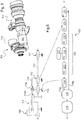
- the Figures 6 to 8 allow to represent a numerical model corresponding to the kinematic system of the propeller propulsion unit of the figure 3 , especially according to the layout of the figure 2 that is to say, where the electric motor 114 is mounted on a stator independent of the primary shaft 112.
- the figures 6 and 8 allow to show that the drive and selection device 115 has an output to which the propeller is coupled.
- FIGS. 9 and 10 show an aircraft according to an exemplary embodiment of the invention.
- the aircraft described below is a transonic aircraft intended for the transport of passengers, and for example allowing, in certain interior layout configurations, the transport of at least 100 passengers.
- the present invention is not limited to such an aircraft and may also relate to aircraft most commonly referred to as "cargo aircraft”.
- the aircraft 300 mainly comprises a fuselage 301 and a wing attached to the fuselage.
- the wing has two wings 302 extending symmetrically on either side of the fuselage 301.
- the fuselage has a front part, a central part and a rear part.
- An empennage 303 is attached to the fuselage 301 in particular at its rear portion.
- the front part of the fuselage here comprises a cockpit 304 inside which is a cockpit.
- the latter comprises in particular all the control elements for piloting the aircraft, control screens, communication means, etc.
- the cockpit can be located elsewhere than in the front part of the fuselage.
- the front part of the fuselage can then be intended for carrying a payload.
- the central part of the fuselage is mainly intended for the transport of a payload.
- the central portion of the fuselage then mainly comprises a cabin for receiving passengers and a cargo hold to receive the luggage of passengers and possibly other goods, arranged under the cabin.
- the aircraft 300 comprises a propeller propulsion unit comprising at least a portion of the characteristics described above.
- the heat engine is for example a gas turbine using as fuel a fuel embedded in the aircraft, and typically kerosene stored in a tank of the aircraft.
- the kinematic system 110 of the propeller propulsion unit is disposed under a wing 302.
- the aircraft here comprises a kinematic system 110 under each wing 302, on either side of the fuselage 301.
- the aircraft further comprises a propeller electric motor 200 and in particular here an electric propeller motor 200 under each wing 302, on either side of the fuselage 301.
- each electric propeller motor 200 is supplied by the storage and power supply means 121 which are loaded by the electrical energy generator 113 of each of the kinematic systems 110 arranged in the aircraft.
- the storage and power supply means 121 are arranged in the fuselage, near the center of gravity of the aircraft.
- each kinematic system 110 is positioned between the corresponding electric propeller motor 200 and the fuselage 301.
- This configuration allows a better distribution of loads.
- each electric propeller motor 200 is positioned between the fuselage 301 and the corresponding kinematic system 110.
- Figures 11 and 12 illustrate means for fixing a kinematic system 110 according to the invention under a wing 302.
- this is a nacelle 305 while in the example of the figure 12 it may be a "turbofan" type fastener 306.
Abstract
L'invention porte sur une unité de propulsion à hélice (100), comportant au moins un système cinématique (110) comprenant au moins : un moteur thermique (111), un générateur d'énergie électrique (113), un moteur électrique (114) configuré pour générer un mouvement rotatif en sortie à partir de l'énergie électrique générée par le générateur d'énergie électrique (113), un dispositif d'entrainement et de sélection (115) configuré pour prendre une première configuration (115a) dans laquelle il est accouplé en sortie du moteur électrique (114) et une deuxième configuration (115b) dans laquelle il est accouplé à l'arbre primaire (112) du moteur thermique (111), et une hélice (116) entrainée en rotation par le dispositif d'entrainement et de sélection (115). Une telle unité de propulsion à hélice à motorisation hybride permet de fournir plus de puissance, et présente une facilité de maintenance et d'ergonomie, et est plus sure.

Description
La présente invention concerne une unité de propulsion à hélice, et en particulier une unité de propulsion à hélice d'aéronef.The present invention relates to a propeller propulsion unit, and in particular an aircraft propeller propulsion unit.
Elle concerne également un aéronef comportant une telle unité de propulsion à hélice, par exemple un aéronef destiné au transport d'une charge utile, comme par exemple un aéronef civil destiné au transport de passagers et/ou au transport de fret.It also relates to an aircraft comprising such a propeller propulsion unit, for example an aircraft intended for the transport of a payload, such as for example a civil aircraft intended for the carriage of passengers and / or the transport of freight.
De manière classique, un aéronef comporte un fuselage, une voilure et un empennage.Conventionally, an aircraft comprises a fuselage, a wing and a tail.
A l'avant du fuselage se trouve un cockpit.At the front of the fuselage is a cockpit.
Derrière le cockpit, le fuselage comporte une partie centrale destinée au transport d'une charge utile. Typiquement, une cabine pour recevoir des passagers se trouve dans la partie centrale du fuselage, avec éventuellement une soute pour transporter du fret. Cette partie centrale peut aussi être aménagée pour ne recevoir que du fret.Behind the cockpit, the fuselage has a central part for transporting a payload. Typically, a cabin for receiving passengers is in the central part of the fuselage, possibly with a cargo hold to transport cargo. This central part can also be arranged to receive only freight.
L'empennage est attaché à une partie arrière du fuselage. Cet empennage est classiquement associé à une dérive.The empennage is attached to a rear part of the fuselage. This empennage is classically associated with a drift.
La partie arrière du fuselage est généralement dédiée au logement de compartiments techniques.The rear part of the fuselage is generally dedicated to the housing of technical compartments.
La voilure, dont la position et la forme dépendent de la conception de l'aéronef, est attachée au fuselage.The wing, whose position and shape depend on the design of the aircraft, is attached to the fuselage.
L'aéronef comporte généralement des moteurs, et par exemple deux moteurs fixés sous la voilure de l'aéronef.The aircraft generally comprises engines, and for example two engines fixed under the wing of the aircraft.
Ces moteurs constituent les moyens de propulsion de l'aéronef et sont typiquement des moteurs à combustion internes, aussi dits moteurs thermiques, alimentés en carburant, lequel est stocké dans un réservoir de l'aéronef.These engines are the propulsion means of the aircraft and are typically internal combustion engines, also called thermal engines, fueled, which is stored in a tank of the aircraft.
Dans un but de réduire la consommation de carburant et les émissions de dioxyde de carbone et autres polluants issus de la combustion pour un tel aéronef, la demande de brevet français n °
Une telle motorisation peut toutefois être améliorée, par exemple en termes de puissance pouvant être fournie, de facilité de maintenance ou d'ergonomie, ou encore de sécurité.Such motorization can however be improved, for example in terms of power that can be provided, ease of maintenance or ergonomics, or security.
La présente invention vise ainsi à améliorer au moins une partie des aspects précités.The present invention thus aims to improve at least some of the aforementioned aspects.
A cet effet, est proposé, selon un premier aspect, une unité de propulsion à hélice, comportant au moins un système cinématique comprenant au moins :
- un moteur thermique consommant du carburant et un arbre primaire entrainé en rotation en sortie du moteur thermique,
- un générateur d'énergie électrique configuré pour générer une énergie électrique à partir de la rotation de l'arbre primaire,
- un moteur électrique configuré pour générer un mouvement rotatif en sortie à partir de l'énergie électrique générée par le générateur d'énergie électrique,
- un dispositif d'entrainement et de sélection configuré pour prendre
- ∘ une première configuration dans laquelle il est accouplé en sortie du moteur électrique et
- ∘ une deuxième configuration dans laquelle il est accouplé à l'arbre primaire,
- une hélice entrainée en rotation par le dispositif d'entrainement et de sélection.
- a heat engine consuming fuel and a primary shaft driven in rotation at the output of the heat engine,
- an electric energy generator configured to generate electrical energy from the rotation of the primary shaft,
- an electric motor configured to generate rotary motion output from the electrical energy generated by the electric power generator,
- a training and selection device configured to take
- A first configuration in which it is coupled to the output of the electric motor and
- A second configuration in which it is coupled to the primary shaft,
- a propeller rotated by the drive and selection device.
Ainsi, le moteur thermique et le générateur d'énergie électrique, d'une part, et le moteur électrique (aussi désigné « EPU » pour « Electrical Power Unit »), d'autre part, sont couplés et agencés derrière l'hélice.Thus, the heat engine and the electrical energy generator, on the one hand, and the electric motor (also called "EPU" for "Electrical Power Unit"), on the other hand, are coupled and arranged behind the propeller.
En cas d'urgence ou de défaillance, il est ainsi possible de remplacer la source d'énergie électrique, c'est-à-dire l'EPU, par la source d'énergie thermique, c'est-à-dire le moteur thermique, grâce à la possibilité d'établir un lien direct entre l'arbre primaire et l'hélice par le dispositif d'entrainement et de sélection qui est configuré pour prendre chacune des deux configurations, mais l'une des deux à un moment donné.In case of emergency or failure, it is thus possible to replace the source of electrical energy, that is to say the UPE, by the source of thermal energy, that is to say the engine thermal, thanks to the possibility of establishing a direct link between the primary shaft and the propeller by the drive and selection device which is configured to take each of the two configurations, but one of them at a given moment .
Il est précisé que « direct » signifie ici « sans impliquer l'utilisation du moteur électrique ».It is stated that "direct" here means "without involving the use of the electric motor".
Une telle unité de propulsion à hélice est alors plus sure puisqu'elle permet de fournir de l'énergie à l'hélice au moyen de deux sources différentes : le moteur thermique et le moteur électrique.Such a propeller propulsion unit is then safer since it can provide energy to the propeller by means of two different sources: the engine and the electric motor.
De plus, alors qu'il s'agit d'une motorisation hybride, la possibilité d'établir un lien direct entre l'arbre rotatif du moteur thermique, c'est-à-dire l'arbre primaire, et l'hélice permet de fournir davantage d'énergie à l'hélice.In addition, while it is a hybrid engine, the possibility of establishing a direct link between the rotary shaft of the engine, that is to say the primary shaft, and the propeller allows to provide more energy to the propeller.
Un positionnement du moteur thermique derrière l'hélice dans le cadre d'une motorisation hybride permet aussi de réduire la trainée.Positioning the engine behind the propeller in the context of a hybrid engine also reduces drag.
Ainsi, une telle unité de propulsion à hélice à motorisation hybride permet de fournir plus de puissance, et présente une facilité de maintenance et d'ergonomie, et est plus sure.Thus, such a hybrid propulsion propulsion unit allows to provide more power, and has an ease of maintenance and ergonomics, and is safer.
Le générateur d'énergie électrique est par exemple possiblement monté sur l'arbre primaire, voire traversé par l'arbre primaire.The electrical energy generator is for example possibly mounted on the primary shaft, or even crossed by the primary shaft.
Le moteur électrique configuré pour générer un mouvement rotatif en sortie comporte par exemple, en sortie, un arbre secondaire et/ou un pignon entrainé en rotation.The electric motor configured to generate a rotary output movement comprises for example, at the output, a secondary shaft and / or a pinion driven in rotation.
Par exemple, le moteur thermique consommant du carburant est un moteur thermique à combustion interne, tel qu'une turbine à gaz ou turbine à combustion.For example, the thermal engine consuming fuel is an internal combustion engine, such as a gas turbine or combustion turbine.
Dans un exemple de réalisation intéressant, le dispositif d'entrainement et de sélection comporte un élément d'accouplement et un élément de guidage configuré pour au moins guider en rotation l'élément d'accouplement.In an interesting embodiment, the training and selection device comprises a coupling element and a guiding element configured to at least guide in rotation the coupling element.
L'élément d'accouplement est par exemple un élément dont au moins une partie est mobile entre une position dans laquelle il est accouplé à l'arbre primaire du moteur thermique et une position dans laquelle il est accouplé à la sortie du moteur électrique.The coupling element is for example an element of which at least a part is movable between a position in which it is coupled to the primary shaft of the heat engine and a position in which it is coupled to the output of the electric motor.
L'élément de guidage est un élément configuré pour au moins guider l'élément d'accouplement entre la configuration dans laquelle il est accouplé à l'arbre primaire du moteur thermique et la configuration dans laquelle il est accouplé à la sortie du moteur électrique, sans bloquer sa rotation.The guide element is an element configured to at least guide the coupling element between the configuration in which it is coupled to the primary shaft of the heat engine and the configuration in which it is coupled to the output of the electric motor, without blocking its rotation.
Par exemple, le dispositif d'entrainement et de sélection comporte un réducteur.For example, the drive and selection device comprises a gearbox.
Le réducteur est par exemple un train épicycloïdal.The reducer is for example an epicyclic gear train.
Dans un exemple de réalisation, le système cinématique comporte en outre un conduit d'échappement de gaz, par exemple positionné en arrière du moteur thermique.In an exemplary embodiment, the kinematic system further comprises a gas exhaust duct, for example positioned behind the engine.
Par exemple, l'unité de propulsion à hélice comporte en outre des moyens de stockage et d'alimentation électrique configurés pour stocker l'énergie électrique générée par le générateur d'énergie électrique et pour alimenter en énergie électrique le moteur électrique.For example, the propeller propulsion unit further comprises storage and power supply means configured to store the electrical energy generated by the electric power generator and to supply electrical energy to the electric motor.
Par exemple, l'unité de propulsion à hélice comporte en outre un redresseur configuré pour transformer un courant alternatif en sortie du générateur d'énergie électrique en courant continu.For example, the propeller propulsion unit further comprises a rectifier configured to convert an alternating current output of the electric power generator into direct current.
Par exemple, le redresseur permet d'alimenter, voire par exemple charger, les moyens de stockage et d'alimentation électrique.For example, the rectifier can power, or even for example load, storage and power supply means.
Par exemple, l'unité de propulsion à hélice comporte en outre un alternateur configuré pour transformer un courant continu en courant alternatif pour alimenter le moteur électrique.For example, the propeller propulsion unit further comprises an alternator configured to convert a direct current to alternating current to power the electric motor.
Par exemple, le courant continu fourni à l'alternateur provient des moyens de stockage et d'alimentation électrique.For example, the direct current supplied to the alternator comes from the storage and power supply means.
En d'autres termes, l'unité de propulsion à hélice comporte en outre un système électrique.In other words, the propeller propulsion unit further comprises an electrical system.
Le système électrique comporte principalement des éléments électriques et/ou électroniques.The electrical system mainly comprises electrical and / or electronic elements.
Le système électrique est configuré pour transmettre de l'énergie électrique depuis le générateur d'énergie électrique au moteur électrique.The electrical system is configured to transmit electrical energy from the electric power generator to the electric motor.
Il comporte par exemple au moins l'un des éléments précités, à savoir : des moyens de stockage et d'alimentation électrique, un redresseur, un alternateur.... Le système électrique peut aussi comporter les différents câbles utiles aux liaisons électriques souhaitées. En d'autre terme, le système électrique comporte différents éléments électriques et/ou électroniques utiles au fonctionnement de l'unité de propulsion à hélice.It comprises for example at least one of the aforementioned elements, namely: storage and power supply means, a rectifier, an alternator .... The electrical system may also include the various cables useful for the desired electrical connections. In other words, the electrical system comprises various electrical and / or electronic elements useful for the operation of the propeller propulsion unit.
L'unité de propulsion à hélice peut aussi comporter un système de refroidissement configuré pour abaisser en température au moins une partie du système cinématique et/ou du système électrique.The propeller propulsion unit may also include a cooling system configured to lower in temperature at least a portion of the kinematic system and / or the electrical system.
Est également proposé, selon un autre aspect, un aéronef comportant au moins une unité de propulsion à hélice.It is also proposed, in another aspect, an aircraft comprising at least one propeller propulsion unit.
L'unité de propulsion à hélice comporte au moins une partie des caractéristiques décrites précédemment.The propeller propulsion unit comprises at least a portion of the features described above.
Une unité de propulsion à hélice comportant au moins une partie des caractéristiques précédemment décrites, dans un aéronef, présente ainsi des avantages analogues à ceux décrits ci-dessus.A propulsion propulsion unit comprising at least a portion of the previously described characteristics in an aircraft, thus has advantages similar to those described above.
Dans le cas d'une installation dans un aéronef, il est en outre possible de réduire des renforts structuraux du fuselage du fait que l'installation du moteur thermique et du générateur électrique se fait alors hors du fuselage.In the case of an installation in an aircraft, it is also possible to reduce structural reinforcements of the fuselage because the installation of the engine and the electric generator is then outside the fuselage.
La réduction des renforts structuraux permet alors un allègement du fuselage.The reduction of the structural reinforcements then allows a lightening of the fuselage.
Le système cinématique de l'unité de propulsion à hélice est par exemple installé à l'extérieur du fuselage de l'aéronef, par exemple sous voilure ou à l'arrière de l'aéronef.The kinematic system of the propulsion propulsion unit is for example installed outside the fuselage of the aircraft, for example under the wing or at the rear of the aircraft.
Par exemple, l'aéronef comporte au moins une aile et le système cinématique est disposé sous l'aile.For example, the aircraft has at least one wing and the kinematic system is disposed under the wing.
Le système cinématique est par exemple fixé sous l'aile par une nacelle ou tout autre type d'attache.The kinematic system is for example fixed under the wing by a nacelle or any other type of fastener.
Les accélérations des moteurs sont réduites par rapport à une installation arrière des moteurs (par exemple 2.5 G au lieu de 8 G).The accelerations of the engines are reduced compared to a rear installation of the engines (for example 2.5 G instead of 8 G).
L'installation du système cinématique est facilitée car elle s'apparente à une installation habituelle de moteur sous aile.The installation of the kinematic system is facilitated because it is similar to a usual installation of engine under wing.
En outre, la maintenance est facilitée car au moins le moteur thermique étant positionné hors du fuselage, le système cinématique est plus facile d'accès et ce d'autant plus lorsqu'il est positionné sous aile par exemple. Il est ainsi possible d'accéder directement au système cinématique alors que lorsque le moteur thermique et le générateur sont positionnés dans le fuselage, il est nécessaire de procéder par une trappe d'accès.In addition, the maintenance is facilitated because at least the engine being positioned outside the fuselage, the kinematic system is easier to access and especially when it is positioned under wing for example. It is thus possible to directly access the kinematic system whereas when the heat engine and the generator are positioned in the fuselage, it is necessary to proceed by an access hatch.
Dans un exemple de réalisation, les moyens de stockage et d'alimentation électrique sont disposés dans le fuselage.In an exemplary embodiment, the storage and power supply means are arranged in the fuselage.
Dans une forme de réalisation, les moyens de stockage et d'alimentation électrique épousent une forme intérieure du fuselage.In one embodiment, the storage and power supply means follow an inner shape of the fuselage.
Dans un exemple de réalisation, les moyens de stockage et d'alimentation électrique sont disposés à proximité du centre de gravité de l'aéronef équipé au moins du système cinématique.In an exemplary embodiment, the storage and power supply means are disposed near the center of gravity of the aircraft equipped with at least the kinematic system.
Par exemple, en d'autres termes, une fois le système cinématique disposé dans l'aéronef, ou tous les systèmes cinématiques si plus sont prévus, par exemple sous aile, il est possible de déterminer un centre de gravité de l'aéronef, muni d'au moins le système cinématique, et alors définir où positionner les moyens de stockage et d'alimentation électrique, au plus près du centre de gravité dans la mesure du possible.For example, in other words, once the kinematic system disposed in the aircraft, or all the kinematic systems if more are provided, for example under wing, it is possible to determine a center of gravity of the aircraft, provided with at least the kinematic system, and then define where to position the storage and power supply means, as close to the center of gravity as possible.
Le poids de l'aéronef muni d'une telle unité de propulsion à hélice est alors concentré vers un centre de gravité de l'aéronef.The weight of the aircraft equipped with such a propulsion propulsion unit is then concentrated towards a center of gravity of the aircraft.
Dans un exemple de réalisation, l'aéronef comporte en outre un moteur électrique à hélice.In an exemplary embodiment, the aircraft further comprises a propeller electric motor.
Un moteur électrique à hélice désigne ici un moteur électrique (EPU) muni d'une hélice.An electric propeller motor here designates an electric motor (EPU) provided with a propeller.
Dans un exemple de réalisation, le moteur électrique à hélice est aussi disposé sous une aile de l'aéronef.In an exemplary embodiment, the electric propeller motor is also disposed under a wing of the aircraft.
Par exemple, le moteur thermique et le générateur d'énergie électrique de l'unité de propulsion à hélice sont configurés pour en outre fournir de l'énergie électrique au moteur électrique à hélice.For example, the heat engine and the electric power generator of the propeller propulsion unit are configured to further supply electrical energy to the electric propeller motor.
Dans un exemple de réalisation, l'aéronef comporte en outre un fuselage et le moteur électrique à hélice est disposé sous l'aile et le système cinématique est positionné entre le moteur électrique à hélice et le fuselage.In an exemplary embodiment, the aircraft further comprises a fuselage and the electric propeller motor is disposed under the wing and the kinematic system is positioned between the electric propeller motor and the fuselage.
Autrement dit, au moins le système cinématique de l'unité de propulsion à hélice et un moteur électrique à hélice indépendant sont tous deux disposés sous une même aile de l'aéronef. Et par exemple, le système cinématique de l'unité de propulsion à hélice est disposé entre le fuselage et le moteur électrique à hélice.In other words, at least the kinematic system of the propeller propulsion unit and an independent propeller electric motor are both arranged under the same wing of the aircraft. And for example, the kinematic system of the propeller propulsion unit is disposed between the fuselage and the electric propeller motor.
En pratique, l'aéronef peut comprendre plusieurs moteurs électriques à hélice. Ils sont par exemple disposés symétriquement de chaque côté du fuselage, et par exemple sous chacune des ailes.In practice, the aircraft can comprise several propeller electric motors. They are for example symmetrically arranged on each side of the fuselage, and for example under each wing.
Par exemple, l'aéronef comporte un système cinématique de chaque côté du fuselage.For example, the aircraft has a kinematic system on each side of the fuselage.
Dans un exemple de réalisation, l'aéronef peut comporter un système électrique commun aux systèmes cinématiques disposés de chaque côté du fuselage.In an exemplary embodiment, the aircraft may comprise an electrical system common to the kinematic systems arranged on each side of the fuselage.
Ainsi, par exemple, les générateurs électriques de chacun des systèmes cinématiques alimentent les mêmes moyens de stockage et d'alimentation électrique.Thus, for example, the electrical generators of each of the kinematic systems supply the same storage and power supply means.
L'invention, selon un exemple de réalisation, sera bien comprise et ses avantages apparaitront mieux à la lecture de la description détaillée qui suit, donnée à titre indicatif et nullement limitatif, en référence aux dessins annexés dans lesquels :
- La
figure 1 montre schématiquement une architecture cinématique d'unité de propulsion à hélice selon un mode de mise en oeuvre de l'invention, - La
figure 2 montre schématiquement une architecture cinématique alternative au mode de mise en oeuvre de lafigure 1 , - La
figure 3 montre schématiquement une unité de propulsion à hélice selon un exemple de réalisation de l'invention, - La
figure 4 illustre le système cinématique de l'unité de propulsion à hélice de lafigure 3 adjoint d'un moteur électrique à hélice alimenté par le moteur thermique et le générateur d'énergie électrique du système cinématique, - La
figure 5 présente un schéma cinématique d'un mode de réalisation du système cinématique de l'unité de propulsion à hélice selon l'invention et un exemple de diagramme bloc de l'unité de propulsion à hélice, - Les
figures 6 et7 présentent une maquette numérique correspondant au système cinématique de l'unité de propulsion à hélice de lafigure 3 , le système cinématique étant dépourvu de l'hélice sur lafigure 6 par rapport à lafigure 7 , - La
figure 8 est une vue partiellement en transparence de la maquette numérique de lafigure 7 , - La
figure 9 présentent un aéronef en trois dimensions selon un exemple de mise en oeuvre de l'invention, - La
figure 10 présentent un aéronef en trois dimensions selon un autre exemple de mise en oeuvre de l'invention, et - Les
figures 11 et 12 illustrent des exemples de systèmes d'attache pour fixer un système cinématique d'une unité de propulsion à hélice selon un exemple de réalisation de l'invention sous une aile d'aéronef.
- The
figure 1 schematically shows a kinematic architecture propeller propulsion unit according to an embodiment of the invention, - The
figure 2 schematically shows an alternative kinematic architecture to the mode of implementation of thefigure 1 , - The
figure 3 schematically shows a propulsion propulsion unit according to an exemplary embodiment of the invention, - The
figure 4 illustrates the kinematic system of the propeller propulsion unit of thefigure 3 assistant of a propeller electric motor powered by the thermal engine and the electrical energy generator of the kinematic system, - The
figure 5 presents a kinematic diagram of an embodiment of the kinematic system of the propulsion propulsion unit according to the invention and an example of a block diagram of the propulsion propulsion unit, - The
figures 6 and7 present a digital model corresponding to the kinematic system of the propeller propulsion unit of thefigure 3 , the kinematic system being devoid of the propeller on thefigure 6 compared to thefigure 7 , - The
figure 8 is a partially transparent view of the digital model of thefigure 7 , - The
figure 9 present an aircraft in three dimensions according to an exemplary implementation of the invention, - The
figure 10 show a three-dimensional aircraft according to another embodiment of the invention, and - The
Figures 11 and 12 illustrate examples of fastening systems for securing a kinematic system of a propeller propulsion unit according to an exemplary embodiment of the invention under an aircraft wing.
Les éléments identiques représentés sur les figures précitées sont identifiés par des références numériques identiques.The identical elements shown in the above figures are identified by identical reference numerals.
Dans la description qui suit, les termes "avant" et "arrière" se réfèrent à l'unité de propulsion à hélice telle qu'elle serait disposée dans un aéronef et/ou à l'aéronef et à son sens de déplacement en vol.In the following description, the terms "front" and "rear" refer to the propeller propulsion unit as it would be disposed in an aircraft and / or the aircraft and its direction of flight in flight.
Les notions de positions relatives, inférieure et supérieure, se repèrent par exemple lorsque l'aéronef est en vol de croisière ou lorsqu'il est posé au sol.The concepts of relative positions, lower and upper, are identified for example when the aircraft is in cruising flight or when it is placed on the ground.
La
L'unité de propulsion à hélice 100 comporte par définition au moins un système cinématique 110 et un système électrique 120.The
Le système cinématique comporte l'hélice et les principaux éléments positionnés en arrière de l'hélice et à laquelle ils sont rattachés mécaniquement, voire aussi cinématiquement.The kinematic system comprises the propeller and the main elements positioned behind the propeller and to which they are attached mechanically or even kinematically.
Le système cinématique 110 comporte au moins :
- un moteur thermique 111 consommant du carburant avec un arbre primaire 112 entrainé en rotation en sortie du moteur thermique, par exemple selon un vitesse angulaire notée « w »,
- un générateur d'énergie électrique 113 configuré pour générer une énergie électrique à partir de la rotation de l'arbre primaire 112,
- un moteur électrique 114 configuré pour générer un mouvement rotatif en sortie (par exemple par tout type d'élément rotatif), à partir de l'énergie électrique générée par le générateur d'énergie électrique 113 et qui lui est transmise,
- un dispositif d'entrainement et de sélection (référencé par
la suite 115 mais dont seul les configurations énoncées ci-dessous le représentent sur cette figure) configuré pour prendre :une première configuration 115a dans laquelle il est accouplé en sortie du moteur électrique 114 etune deuxième configuration 115b dans laquelle il est accouplé à l'arbre primaire 112, et
une hélice 116 entrainée en rotation par le dispositif d'entrainement et de sélection 115.
- a
heat engine 111 consuming fuel with aprimary shaft 112 rotated at the output of the heat engine, for example at an angular velocity denoted "w", - an
electric energy generator 113 configured to generate electrical energy from the rotation of theprimary shaft 112, - an
electric motor 114 configured to generate a rotary output movement (for example by any type of rotary element), from the electrical energy generated by theelectric energy generator 113 and transmitted to it, - a training and selection device (referenced subsequently 115 but only the configurations listed below represent it in this figure) configured to take:
- a
first configuration 115a in which it is coupled at the output of theelectric motor 114 and - a
second configuration 115b in which it is coupled to theprimary shaft 112, and
- a
- a
propeller 116 rotated by the drive andselection device 115.
Le moteur thermique 111 consommant du carburant est par exemple un moteur thermique à combustion interne, tel qu'une turbine à gaz ou turbine à combustion.The
Le système électrique 120 comporte principalement des éléments électriques et/ou électroniques.The
Le système électrique 120 est configuré pour transmettre de l'énergie électrique depuis le générateur d'énergie électrique 113 au moteur électrique 114.The
Il comporte par exemple au moins des câbles ou autres éléments de liaison, référencés indifféremment par la référence 124, permettant de transmettre de l'énergie électrique depuis le générateur d'énergie électrique 113 au moteur électrique 114.It comprises for example at least cables or other connecting elements, referenced indifferently by the
Ainsi, en conditions dites « normales » d'utilisation, la première configuration 115a est impliquée, alors qu'en cas de besoin de surpuissance, par exemple lors d'un décollage d'un aéronef ou d'une manoeuvre spéciale, ou en cas d'urgence, par exemple en cas de défaillance du moteur électrique et/ou du générateur, la deuxième configuration 115b peut être mise en fonctionnement.Thus, in so-called "normal" conditions of use, the
Le dispositif d'entrainement et de sélection 115 est donc configuré pour prendre au choix chacune des deux configurations.The training and
L'exemple de réalisation de la
De plus, l'arbre primaire 112 comporte par exemple un pignon, ou tout autre type de roue dentée (incluant même une couronne), configuré pour s'accoupler à un élément d'accouplement du dispositif d'entrainement et de sélection 115 dans la deuxième configuration 115b.In addition, the
Dans l'exemple de réalisation de la
L'élément rotatif en sortie du moteur électrique 114 est par exemple un arbre, dit ici arbre secondaire, éventuellement muni d'un pignon, ou tout autre type de roue dentée (incluant même une couronne).The rotary element at the output of the
L'élément rotatif en sortie du moteur électrique 114 est par exemple l'élément configuré pour s'accoupler à un élément d'accouplement du dispositif d'entrainement et de sélection 115 dans la première configuration 115a.The rotary element at the output of the
Ainsi, de manière générale, le dispositif d'entrainement et de sélection 115 comporte au moins un élément d'accouplement configuré pour s'accoupler soit à l'arbre primaire 112 soit à l'élément rotatif en sortie du moteur électrique 114.Thus, in general, the drive and
Dans un exemple de réalisation illustré en
L'exemple de réalisation de la
Dans un autre exemple de réalisation, l'élément rotatif en sortie du moteur électrique et le pignon, ou tout autre type de roue dentée (incluant même une couronne), de l'arbre primaire 112 pourraient toutefois être à une même distance derrière l'hélice pour entraîner l'hélice.In another embodiment, the rotary element at the output of the electric motor and the pinion, or any other type of toothed wheel (including even a crown), of the
Le générateur d'énergie électrique 113 alimenté par le moteur thermique 111 est uniquement dédié à la production d'électricité et ne produit pas de poussée utile dans le système cinématique 110 de l'unité de propulsion à hélice 100.The
La
L'un ou l'autre des agencements présentés en
Cette figure illustre en outre le fait que le moteur thermique 111 est alimenté en carburant F (lequel est généralement stocké dans un réservoir indépendant de l'unité de propulsion à hélice décrite ici).This figure further illustrates that the
Le système cinématique peut aussi comporter un conduit d'échappement de gaz 118.The kinematic system may also include a
Un tel conduit d'échappement de gaz 118 est typiquement positionné en arrière du moteur thermique 111.Such a
En particulier, une surface interne du conduit d'échappement de gaz 118 (c'est-à-dire celle destinée à être en contact avec des gaz d'échappement) peut présenter une surface active de traitement des gaz d'échappement afin de diminuer l'émission de polluants dans l'atmosphère.In particular, an inner surface of the gas exhaust duct 118 (that is to say that intended to be in contact with exhaust gas) may have an active exhaust gas treatment surface to reduce the emission of pollutants into the atmosphere.
La surface active du conduit d'échappement de gaz interagit avec les gaz d'échappement pour les traiter.The active surface of the gas exhaust duct interacts with the exhaust gases to treat them.
A titre d'exemple, cette surface active peut être réalisée par dépôt catalytique similaire à ceux utilisés dans les pots d'échappement des véhicules automobiles.For example, this active surface can be made by catalytic deposition similar to those used in the exhaust pipes of motor vehicles.
Une telle surface active est adaptée à traiter directement les gaz d'échappement en sortie du moteur thermique, et notamment les gaz issus de la combustion d'une turbine.Such an active surface is adapted to directly treat the exhaust gas at the output of the heat engine, and in particular the gases resulting from the combustion of a turbine.
Cette
Sur cette figure, le système électrique 120 comporte, par définition :
un redresseur 122 configuré pour transformer un courant alternatif en sortie du générateur d'énergie électrique 113 en courant continu,- des moyens de stockage et d'alimentation électrique 121 configurés pour stocker l'énergie électrique générée par le générateur d'énergie électrique 113 et pour alimenter en énergie électrique le moteur électrique 114,
un alternateur 123 configuré pour transformer un courant continu, notamment issu des moyens de stockage et d'alimentation électrique 121, en courant alternatif pour alimenter le moteur électrique 114 et- des câbles ou autres éléments de liaison, référencés indifféremment par la référence 124, permettant de transmettre de l'énergie électrique depuis le générateur d'énergie électrique 113 au moteur électrique 114, et en particulier entre le redresseur 122 et les moyens de stockage et d'alimentation électrique 121 et entre les moyens de stockage et d'alimentation électrique 121 et l'alternateur 123, ainsi qu'entre le générateur d'énergie électrique 113 et le redresseur 122 et entre l'alternateur 123 et le moteur électrique 114.
- a
rectifier 122 configured to transform an alternating current at the output of theelectric power generator 113 into direct current, - storage and power supply means 121 configured to store the electrical energy generated by the
electric energy generator 113 and to supply electrical energy to theelectric motor 114, - an
alternator 123 configured to transform a direct current, in particular from the storage and power supply means 121, into alternating current for supplying theelectric motor 114 and - cables or other connecting elements, referenced indifferently by the
reference 124, for transmitting electrical energy from theelectric power generator 113 to theelectric motor 114, and in particular between therectifier 122 and the storage and control means. 121 and between the power supply and storage means 121 and thealternator 123, and between theelectric power generator 113 and therectifier 122 and between thealternator 123 and theelectric motor 114.
Bien entendu cette disposition n'est pas limitative et le système électrique 120 peut comporter d'autres éléments.Of course this provision is not limiting and the
Ainsi, le générateur d'énergie électrique 113 est adapté à alimenter les moyens de stockage et d'alimentation électrique 121.Thus, the
Les moyens de stockage et d'alimentation électrique 121 sont par exemple constitués d'au moins une batterie adaptée à stocker l'énergie électrique provenant du générateur d'énergie électrique 113. Il s'agit par exemple de plusieurs batteries en parallèle.The storage and power supply means 121 consist for example of at least one battery adapted to store the electrical energy from the
Les moyens de stockage et d'alimentation électrique 121 sont utilisés pour alimenter en courant électrique au moins le moteur électrique 114.The storage and power supply means 121 are used to supply electrical power to at least the
De préférence, ils servent aussi à assurer une alimentation électrique suffisante du moteur électrique en cas de panne du générateur d'énergie électrique 113.Preferably, they are also used to ensure a sufficient power supply of the electric motor in case of failure of the
Enfin, la
Le système de refroidissement 130 est configuré pour refroidir au moins une partie du système cinématique 110 et/ou du système électrique 120.The
La
Le moteur électrique à hélice 200 comporte ici un moteur électrique 201 et une hélice 202, ainsi qu'éventuellement tout élément (comme par exemple un train d'engrenage) utile à l'adaptation de la vitesse de rotation entre une sortie du moteur électrique et l'hélice. En outre, le moteur électrique à hélice 200 désigne ici une unité dépourvue d'un moteur thermique propre.The propeller
Ainsi, au moins le générateur d'énergie électrique 113 du système cinématique 110 de l'unité de propulsion à hélice selon l'invention est configuré pour alimenter le moteur électrique à hélice 200, en plus du moteur électrique 114 du système cinématique 110 de l'unité de propulsion à hélice même. Ainsi, en d'autres termes par exemple, le générateur d'énergie électrique 113 alimentent alors deux moteurs électriques.Thus, at least the
A cet effet, le générateur d'énergie électrique 113 est relié électriquement, par au moins une liaison électrique (laquelle est ici représenté schématiquement par un trait épais), au moteur électrique 201 du moteur électrique à hélice 200.For this purpose, the
Dans un exemple de réalisation, le système électrique 120 de l'unité de propulsion à hélice 100 comporte une liaison électrique supplémentaire configurée pour connecter les moyens de stockage et d'alimentation électrique 121, voire l'alternateur 123, au moteur électrique 201 du moteur électrique à hélice 200.In an exemplary embodiment, the
La
D'après ce schéma cinématique, le moteur thermique 111 entraine en rotation l'arbre primaire 112.According to this kinematic diagram, the
L'arbre primaire 112 traverse le générateur d'énergie électrique 113 et le moteur électrique 114 et comporte, ici au-delà du moteur électrique 114, une roue dentée, de type pignon par exemple. Le générateur d'énergie électrique 113 et le moteur électrique 114 sont par exemple reliés à l'arbre primaire 112 par des liaisons pivots.The
Comme illustré, le moteur thermique 111 et le générateur d'énergie électrique 113 sont fixes, par exemple par rapport à une référence (celle-ci pouvant être un carter par exemple, et/ou un aéronef dans lequel ils sont disposés).As illustrated, the
Le moteur électrique 114 alimenté par le générateur d'énergie électrique 113 est ici représenté par son élément rotatif en sortie, par exemple une roue dentée (par exemple de type pignon).The
Le dispositif d'entrainement et de sélection 115 comporte ici un élément d'accouplement 119.The drive and
Comme évoqué précédemment, l'élément d'accouplement 119 est configuré pour s'accoupler soit à l'arbre primaire 112, en particulier ici à sa roue dentée, soit à l'élément rotatif en sortie du moteur électrique 114, en particulier ici à sa roue dentée.As mentioned above, the
L'élément d'accouplement 119 comporte ici par exemple un arbre muni d'une roue dentée, laquelle, par translation de l'arbre et/ou de la roue dentée par rapport à l'arbre, peut s'accoupler soit à la roue dentée de l'arbre primaire (deuxième configuration 115b dans laquelle la roue dentée est représentée en pointillés), soit à la roue dentée en sortie du moteur électrique 114 (première configuration 115a dans laquelle la roue dentée est représentée en trait plein).The
Ainsi, ceci illustre que de manière générale, le dispositif d'entrainement et de sélection 115 peut comporter un seul élément d'accouplement 119 configuré pour prendre la première configuration 115a ou la deuxième configuration 115b.Thus, this illustrates that in general, the drive and
En outre, comme illustré sur cette figure, le dispositif d'entrainement et de sélection 115 peut aussi comporter un élément de guidage 117.In addition, as illustrated in this figure, the drive and
Par souci de simplification de la figure, le dispositif d'entrainement et de sélection 115 est ici représenté très schématiquement par l'élément de guidage 117 et l'élément d'accouplement 119.For the sake of simplification of the figure, the drive and
L'élément de guidage 117, schématisé ici de manière très simplifiée, permet par exemple d'adapter la vitesse de rotation de l'élément d'accouplement 119 à une vitesse de rotation souhaitée pour l'hélice 116.The
A titre d'exemple, l'hélice 116 comporte ici une couronne configurée pour s'accoupler en sortie du dispositif d'entrainement et de sélection 115. Dans un exemple particulier, l'hélice peut être accouplée en sortie de l'arbre de l'élément d'accouplement 119 par exemple. L'hélice est par exemple reliée par une liaison pivot à un axe fixe, par exemple par rapport à une référence (celle-ci pouvant être un carter par exemple et/ou l'aéronef, voire le même que celui mentionné précédemment).For example, the
Le diagramme bloc de la
Ainsi, du carburant F est injecté dans le moteur thermique 111 lequel en entrainant en rotation l'arbre primaire (à vitesse angulaire w par exemple) alimente le générateur d'énergie électrique 113 qui génère un courant alternatif (AC).Thus, fuel F is injected into the
La redresseur 122 transforme le courant alternatif (AC) en courant continu (DC) lequel est acheminé vers les moyens de stockage et d'alimentation électrique 121 au moyen de câbles ou autres éléments de liaison, référencés indifféremment par la référence 124.The
Les moyens de stockage et d'alimentation électrique 121 fournissent un courant continu (DC) à l'alternateur 123 qui transforme ce courant continu (DC) en courant alternatif (AC) pour alimenter le moteur électrique 114.The storage and power supply means 121 supply a direct current (DC) to the
Le moteur électrique 114 fournit ensuite en sortie un mouvement rotatif, par exemple à vitesse angulaire w', qui peut néanmoins être la même que celle du moteur thermique.The
Le dispositif d'entrainement et de sélection 115 est configuré pour prendre une première configuration 115a dans laquelle il est accouplé en sortie du moteur électrique 114 et une deuxième configuration 115b dans laquelle il est accouplé en sortie du moteur thermique 111 (soit notamment à l'arbre primaire).The drive and
Enfin, l'hélice 116 est entrainée en rotation par le dispositif d'entrainement et de sélection 115.Finally, the
Les
Les
Les
A titre d'exemple non limitatif, l'aéronef décrit ci-après est un aéronef transsonique destiné au transport de passagers, et par exemple permettant, dans certaines configurations d'aménagement intérieur, le transport d'au moins cent passagers.By way of nonlimiting example, the aircraft described below is a transonic aircraft intended for the transport of passengers, and for example allowing, in certain interior layout configurations, the transport of at least 100 passengers.
Toutefois, la présente invention ne se limite pas à un tel aéronef et peut également concerner des aéronefs appelés le plus couramment « avion-cargo ».However, the present invention is not limited to such an aircraft and may also relate to aircraft most commonly referred to as "cargo aircraft".
Comme bien illustré sur les figures, l'aéronef 300 comporte principalement un fuselage 301 et une voilure attachée au fuselage.As well illustrated in the figures, the
La voilure comporte deux ailes 302 s'étendant symétriquement de part et d'autre du fuselage 301.The wing has two
Le fuselage comporte une partie avant, une partie centrale et une partie arrière.The fuselage has a front part, a central part and a rear part.
Un empennage 303 est attaché au fuselage 301 en particulier à sa partie arrière.An
La partie avant du fuselage comporte ici un cockpit 304 à l'intérieur duquel se trouve un poste de pilotage. Ce dernier comporte notamment tous les éléments de commande pour le pilotage de l'aéronef, des écrans de contrôle, des moyens de communication, ...The front part of the fuselage here comprises a
Bien entendu, le cockpit peut être disposé ailleurs que dans la partie avant du fuselage. La partie avant du fuselage peut alors être destinée au transport d'une charge utile.Of course, the cockpit can be located elsewhere than in the front part of the fuselage. The front part of the fuselage can then be intended for carrying a payload.
La partie centrale du fuselage est principalement destinée au transport d'une charge utile.The central part of the fuselage is mainly intended for the transport of a payload.
Si la charge utile est essentiellement composée de passagers, la partie centrale du fuselage comporte alors principalement une cabine destinée à recevoir les passagers et une soute pour recevoir les bagages des passagers et éventuellement d'autres marchandises, aménagée sous la cabine.If the payload is essentially composed of passengers, the central portion of the fuselage then mainly comprises a cabin for receiving passengers and a cargo hold to receive the luggage of passengers and possibly other goods, arranged under the cabin.
Une telle configuration est tout à fait classique dans un aéronef et n'a pas besoin d'être détaillée ici.Such a configuration is quite conventional in an aircraft and need not be detailed here.
Comme illustré sur les
A titre d'exemple non limitatif, le moteur thermique est par exemple une turbine à gaz utilisant comme combustible un carburant embarqué dans l'aéronef, et typiquement du kérosène stocké dans un réservoir de l'aéronef.By way of non-limiting example, the heat engine is for example a gas turbine using as fuel a fuel embedded in the aircraft, and typically kerosene stored in a tank of the aircraft.
Sur ces figures, le système cinématique 110 de l'unité de propulsion à hélice est disposé sous une aile 302.In these figures, the
En particulier, l'aéronef comporte ici un système cinématique 110 sous chaque aile 302, de part et d'autre du fuselage 301.In particular, the aircraft here comprises a
L'aéronef comporte en outre un moteur électrique à hélice 200 et en particulier ici un moteur électrique à hélice 200 sous chaque aile 302, de part et d'autre du fuselage 301.The aircraft further comprises a propeller
De plus, comme décrit en lien avec la
En outre, comme l'illustre la
Dans l'exemple de réalisation de la
Cette configuration permet une meilleure répartition des charges.This configuration allows a better distribution of loads.
En alternative, dans l'exemple de réalisation de la
Enfin les
Dans l'exemple de la
Il s'agit par exemple d'un moyen connu des hommes du métier basé sur le principe d'attache d'un mât sous voilure pour un turboréacteur.This is for example a means known to those skilled in the art based on the principle of attaching a mast under wings for a turbojet engine.
Claims (13)
Applications Claiming Priority (1)
| Application Number | Priority Date | Filing Date | Title |
|---|---|---|---|
| FR1852804A FR3079498B1 (en) | 2018-03-30 | 2018-03-30 | PROPELLER UNIT COMPRISING A HEAT MOTOR AND AN ELECTRIC MOTOR AND AIRCRAFT COMPRISING SUCH A PROPELLER UNIT |
Publications (2)
| Publication Number | Publication Date |
|---|---|
| EP3546366A1 true EP3546366A1 (en) | 2019-10-02 |
| EP3546366B1 EP3546366B1 (en) | 2021-09-22 |
Family
ID=62751076
Family Applications (1)
| Application Number | Title | Priority Date | Filing Date |
|---|---|---|---|
| EP19165911.9A Active EP3546366B1 (en) | 2018-03-30 | 2019-03-28 | Propulsion unit with propeller comprising a thermal engine and an electric engine as well as aircraft comprising such a propulsion unit with propeller |
Country Status (4)
| Country | Link |
|---|---|
| US (1) | US11897622B2 (en) |
| EP (1) | EP3546366B1 (en) |
| CN (1) | CN110316387A (en) |
| FR (1) | FR3079498B1 (en) |
Cited By (1)
| Publication number | Priority date | Publication date | Assignee | Title |
|---|---|---|---|---|
| GB2587679A (en) * | 2019-10-02 | 2021-04-07 | Advanced Mobility Res And Development Ltd | Systems, arrangements, structures and methods for aircraft |
Families Citing this family (2)
| Publication number | Priority date | Publication date | Assignee | Title |
|---|---|---|---|---|
| GB201918281D0 (en) * | 2019-12-12 | 2020-01-29 | Rolls Royce Plc | Aircraft hybrid propulsion system |
| US11408340B2 (en) | 2020-05-15 | 2022-08-09 | Pratt & Whitney Canada Corp. | Twin-engine system with electric drive |
Citations (8)
| Publication number | Priority date | Publication date | Assignee | Title |
|---|---|---|---|---|
| EP1355610A1 (en) | 2001-01-29 | 2003-10-29 | Hollert, Astrid | Device for inserting a needle-shaped body into living tissue |
| EP2226487A2 (en) * | 2009-03-02 | 2010-09-08 | Rolls-Royce plc | Variable drive gas turbine engine |
| DE102010021026A1 (en) * | 2010-05-19 | 2011-11-24 | Eads Deutschland Gmbh | Hybrid propulsion and power system for aircraft |
| US20140010652A1 (en) * | 2012-07-09 | 2014-01-09 | Mcmaster University | Hybrid powertrain system |
| US20150075167A1 (en) * | 2008-11-14 | 2015-03-19 | Hybrid Innovation Technologies Llc | Electronic system and method of automating, controlling, and optimizing the operation of one or more energy storage units and a combined serial and parallel hybrid marine propulsion system |
| KR20160010355A (en) * | 2014-07-17 | 2016-01-27 | 에어버스 헬리콥터스 | An electrical architecture for an aircraft, an aircraft, and a method of using it |
| DE102014224637A1 (en) * | 2014-12-02 | 2016-06-02 | Georgi Atanasov | Hybrid electric propulsion system for an aircraft |
| US20170225573A1 (en) * | 2014-09-23 | 2017-08-10 | Sikorsky Aircraft Corporation | Hybrid electric power drive system for a rotorcraft |
Family Cites Families (13)
| Publication number | Priority date | Publication date | Assignee | Title |
|---|---|---|---|---|
| US2462201A (en) * | 1943-02-02 | 1949-02-22 | Westinghouse Electric Corp | Electrical airplane propulsion |
| US8636241B2 (en) * | 2005-04-20 | 2014-01-28 | Richard H. Lugg | Hybrid jet/electric VTOL aircraft |
| DE102006055426A1 (en) | 2006-11-22 | 2008-05-29 | Evonik Röhm Gmbh | Process for the preparation of alkyl (meth) acrylates using enzymatic cyanohydrin hydrolysis |
| FR2945268B1 (en) * | 2009-05-05 | 2013-05-17 | Airbus France | ELECTRIC GENERATOR ON A ROTATING PART OF A TURBOPROPULSEUR |
| DE102012209807A1 (en) * | 2012-06-12 | 2013-12-12 | Siemens Aktiengesellschaft | Airplane and method for manufacturing an aircraft |
| FR2992630B1 (en) * | 2012-06-29 | 2015-02-20 | Turbomeca | METHOD AND CONFIGURATION OF PROPULSIVE AND / OR NON-PROPULSIVE ENERGY DELIVERY IN A HELICOPTER ARCHITECTURE BY A POWER AUXILIARY ENGINE |
| ES2500015B1 (en) * | 2013-02-28 | 2015-06-23 | Axter Aerospace S.L. | Electric auxiliary power system for piston engine aircraft |
| FR3006997B1 (en) | 2013-06-14 | 2016-12-23 | Airbus | AIRCRAFT WITH ELECTRICAL PROPULSION MEANS |
| US9643729B2 (en) * | 2014-06-20 | 2017-05-09 | Electronair Llc | Energy cell regenerative system for electrically powered aircraft |
| FR3029172B1 (en) * | 2014-11-27 | 2018-05-25 | Safran Helicopter Engines | PROPULSE GROUP WITH SELECTIVE COUPLING MEANS |
| US10717539B2 (en) * | 2016-05-05 | 2020-07-21 | Pratt & Whitney Canada Corp. | Hybrid gas-electric turbine engine |
| US10604266B2 (en) * | 2016-05-16 | 2020-03-31 | Rolls-Royce Corporation | Electrical assist for aircraft |
| CN106184779A (en) * | 2016-09-19 | 2016-12-07 | 中电科芜湖钻石飞机设计研究院有限公司 | A kind of hybrid power aeroplane coupled system |
-
2018
- 2018-03-30 FR FR1852804A patent/FR3079498B1/en not_active Expired - Fee Related
-
2019
- 2019-03-28 EP EP19165911.9A patent/EP3546366B1/en active Active
- 2019-03-28 US US16/368,305 patent/US11897622B2/en active Active
- 2019-03-29 CN CN201910250550.1A patent/CN110316387A/en active Pending
Patent Citations (8)
| Publication number | Priority date | Publication date | Assignee | Title |
|---|---|---|---|---|
| EP1355610A1 (en) | 2001-01-29 | 2003-10-29 | Hollert, Astrid | Device for inserting a needle-shaped body into living tissue |
| US20150075167A1 (en) * | 2008-11-14 | 2015-03-19 | Hybrid Innovation Technologies Llc | Electronic system and method of automating, controlling, and optimizing the operation of one or more energy storage units and a combined serial and parallel hybrid marine propulsion system |
| EP2226487A2 (en) * | 2009-03-02 | 2010-09-08 | Rolls-Royce plc | Variable drive gas turbine engine |
| DE102010021026A1 (en) * | 2010-05-19 | 2011-11-24 | Eads Deutschland Gmbh | Hybrid propulsion and power system for aircraft |
| US20140010652A1 (en) * | 2012-07-09 | 2014-01-09 | Mcmaster University | Hybrid powertrain system |
| KR20160010355A (en) * | 2014-07-17 | 2016-01-27 | 에어버스 헬리콥터스 | An electrical architecture for an aircraft, an aircraft, and a method of using it |
| US20170225573A1 (en) * | 2014-09-23 | 2017-08-10 | Sikorsky Aircraft Corporation | Hybrid electric power drive system for a rotorcraft |
| DE102014224637A1 (en) * | 2014-12-02 | 2016-06-02 | Georgi Atanasov | Hybrid electric propulsion system for an aircraft |
Cited By (2)
| Publication number | Priority date | Publication date | Assignee | Title |
|---|---|---|---|---|
| GB2587679A (en) * | 2019-10-02 | 2021-04-07 | Advanced Mobility Res And Development Ltd | Systems, arrangements, structures and methods for aircraft |
| WO2021064383A3 (en) * | 2019-10-02 | 2021-07-08 | Electric Aviation Group Ltd | Aircraft power system structure comprising electric generator |
Also Published As
| Publication number | Publication date |
|---|---|
| EP3546366B1 (en) | 2021-09-22 |
| US20190300186A1 (en) | 2019-10-03 |
| FR3079498B1 (en) | 2020-06-19 |
| FR3079498A1 (en) | 2019-10-04 |
| CN110316387A (en) | 2019-10-11 |
| US11897622B2 (en) | 2024-02-13 |
Similar Documents
| Publication | Publication Date | Title |
|---|---|---|
| EP3546366B1 (en) | Propulsion unit with propeller comprising a thermal engine and an electric engine as well as aircraft comprising such a propulsion unit with propeller | |
| EP2574546B1 (en) | Hybriddrehflügelflugzeug | |
| EP2981470B1 (en) | System for recovering and converting kinetic energy and potential energy into electrical energy for an aircraft | |
| EP3628593A1 (en) | Multirotor aircraft with hybrid or electric engine with optimised energy consumption | |
| EP3031730B1 (en) | Aircraft and method for arranging such an aircraft | |
| WO2020225510A1 (en) | Hybrid propulsion system for vertical take-off and landing aircraft | |
| FR2966804A1 (en) | AERODYNE COMPRISING MOTORIZED LANDING TRAINS | |
| FR3084318A1 (en) | METHOD AND DEVICE FOR MANAGING THE ENERGY OF A HYBRID POWER PLANT OF A MULTIROTOR AIRCRAFT | |
| FR2864030A1 (en) | Convertiplane, has two tilt fans arranged on both sides of fuselage, another fan arranged between two tail booms, and openings evacuate exhaust gas from two engines on top of fuselage | |
| FR2957207A1 (en) | ELECTROMOTEUR GROUP DISTRIBUTED. | |
| FR2949434A1 (en) | AIRCRAFT COMPRISING AT LEAST TWO ELECTRIC MOTOR PURPOSE MOUNTED ON THE BACK | |
| FR2976555A1 (en) | Method for performing energetic management of e.g. helicopter, involves adjusting pitch of propeller if thrust is zero or negative such that rotation of propeller allows machine system to generate electrical energy | |
| FR3092926A1 (en) | Hybrid propulsion vertical take-off and landing aircraft equipped with an on-board automatic energy management system | |
| EP3828082B1 (en) | Hybrid rotorcraft comprising at least one pusher or tractor propeller and associated control method | |
| EP3883854B1 (en) | Propulsion system for an aircraft and functioning method of such a system | |
| WO2018055287A1 (en) | Pressurised-air supply unit for an aircraft | |
| FR2943622A3 (en) | MOTORIZED ULTRALOGEN APPARATUS | |
| FR3110896A1 (en) | Electrical architecture of an aircraft | |
| WO2020070438A1 (en) | Electric architecture for hybrid propulsion | |
| FR3120053A1 (en) | METHOD FOR OPERATING AN AIRCRAFT ACCORDING TO AN OPERATING MODE | |
| WO2020025885A1 (en) | Vertical take-off and landing aircraft | |
| FR3133592A1 (en) | Improved turbomachine for hybrid aircraft | |
| FR3096659A1 (en) | Machine comprising a hybrid powertrain and corresponding control method | |
| WO2021250330A1 (en) | Hybrid dual-power-supply electric power chain for a single-propeller aeroplane | |
| FR3134079A1 (en) | Propeller plane |
Legal Events
| Date | Code | Title | Description |
|---|---|---|---|
| PUAI | Public reference made under article 153(3) epc to a published international application that has entered the european phase |
Free format text: ORIGINAL CODE: 0009012 |
|
| STAA | Information on the status of an ep patent application or granted ep patent |
Free format text: STATUS: THE APPLICATION HAS BEEN PUBLISHED |
|
| AK | Designated contracting states |
Kind code of ref document: A1 Designated state(s): AL AT BE BG CH CY CZ DE DK EE ES FI FR GB GR HR HU IE IS IT LI LT LU LV MC MK MT NL NO PL PT RO RS SE SI SK SM TR |
|
| AX | Request for extension of the european patent |
Extension state: BA ME |
|
| STAA | Information on the status of an ep patent application or granted ep patent |
Free format text: STATUS: REQUEST FOR EXAMINATION WAS MADE |
|
| 17P | Request for examination filed |
Effective date: 20200302 |
|
| RBV | Designated contracting states (corrected) |
Designated state(s): AL AT BE BG CH CY CZ DE DK EE ES FI FR GB GR HR HU IE IS IT LI LT LU LV MC MK MT NL NO PL PT RO RS SE SI SK SM TR |
|
| STAA | Information on the status of an ep patent application or granted ep patent |
Free format text: STATUS: EXAMINATION IS IN PROGRESS |
|
| 17Q | First examination report despatched |
Effective date: 20200731 |
|
| STAA | Information on the status of an ep patent application or granted ep patent |
Free format text: STATUS: EXAMINATION IS IN PROGRESS |
|
| GRAP | Despatch of communication of intention to grant a patent |
Free format text: ORIGINAL CODE: EPIDOSNIGR1 |
|
| STAA | Information on the status of an ep patent application or granted ep patent |
Free format text: STATUS: GRANT OF PATENT IS INTENDED |
|
| INTG | Intention to grant announced |
Effective date: 20210423 |
|
| GRAS | Grant fee paid |
Free format text: ORIGINAL CODE: EPIDOSNIGR3 |
|
| GRAA | (expected) grant |
Free format text: ORIGINAL CODE: 0009210 |
|
| STAA | Information on the status of an ep patent application or granted ep patent |
Free format text: STATUS: THE PATENT HAS BEEN GRANTED |
|
| AK | Designated contracting states |
Kind code of ref document: B1 Designated state(s): AL AT BE BG CH CY CZ DE DK EE ES FI FR GB GR HR HU IE IS IT LI LT LU LV MC MK MT NL NO PL PT RO RS SE SI SK SM TR |
|
| REG | Reference to a national code |
Ref country code: GB Ref legal event code: FG4D Free format text: NOT ENGLISH |
|
| REG | Reference to a national code |
Ref country code: IE Ref legal event code: FG4D Free format text: LANGUAGE OF EP DOCUMENT: FRENCH |
|
| REG | Reference to a national code |
Ref country code: DE Ref legal event code: R096 Ref document number: 602019007780 Country of ref document: DE |
|
| REG | Reference to a national code |
Ref country code: CH Ref legal event code: EP Ref country code: AT Ref legal event code: REF Ref document number: 1432154 Country of ref document: AT Kind code of ref document: T Effective date: 20211015 |
|
| REG | Reference to a national code |
Ref country code: LT Ref legal event code: MG9D |
|
| REG | Reference to a national code |
Ref country code: NL Ref legal event code: MP Effective date: 20210922 |
|
| PG25 | Lapsed in a contracting state [announced via postgrant information from national office to epo] |
Ref country code: SE Free format text: LAPSE BECAUSE OF FAILURE TO SUBMIT A TRANSLATION OF THE DESCRIPTION OR TO PAY THE FEE WITHIN THE PRESCRIBED TIME-LIMIT Effective date: 20210922 Ref country code: RS Free format text: LAPSE BECAUSE OF FAILURE TO SUBMIT A TRANSLATION OF THE DESCRIPTION OR TO PAY THE FEE WITHIN THE PRESCRIBED TIME-LIMIT Effective date: 20210922 Ref country code: FI Free format text: LAPSE BECAUSE OF FAILURE TO SUBMIT A TRANSLATION OF THE DESCRIPTION OR TO PAY THE FEE WITHIN THE PRESCRIBED TIME-LIMIT Effective date: 20210922 Ref country code: NO Free format text: LAPSE BECAUSE OF FAILURE TO SUBMIT A TRANSLATION OF THE DESCRIPTION OR TO PAY THE FEE WITHIN THE PRESCRIBED TIME-LIMIT Effective date: 20211222 Ref country code: HR Free format text: LAPSE BECAUSE OF FAILURE TO SUBMIT A TRANSLATION OF THE DESCRIPTION OR TO PAY THE FEE WITHIN THE PRESCRIBED TIME-LIMIT Effective date: 20210922 Ref country code: BG Free format text: LAPSE BECAUSE OF FAILURE TO SUBMIT A TRANSLATION OF THE DESCRIPTION OR TO PAY THE FEE WITHIN THE PRESCRIBED TIME-LIMIT Effective date: 20211222 Ref country code: LT Free format text: LAPSE BECAUSE OF FAILURE TO SUBMIT A TRANSLATION OF THE DESCRIPTION OR TO PAY THE FEE WITHIN THE PRESCRIBED TIME-LIMIT Effective date: 20210922 |
|
| REG | Reference to a national code |
Ref country code: AT Ref legal event code: MK05 Ref document number: 1432154 Country of ref document: AT Kind code of ref document: T Effective date: 20210922 |
|
| PG25 | Lapsed in a contracting state [announced via postgrant information from national office to epo] |
Ref country code: LV Free format text: LAPSE BECAUSE OF FAILURE TO SUBMIT A TRANSLATION OF THE DESCRIPTION OR TO PAY THE FEE WITHIN THE PRESCRIBED TIME-LIMIT Effective date: 20210922 Ref country code: GR Free format text: LAPSE BECAUSE OF FAILURE TO SUBMIT A TRANSLATION OF THE DESCRIPTION OR TO PAY THE FEE WITHIN THE PRESCRIBED TIME-LIMIT Effective date: 20211223 |
|
| PG25 | Lapsed in a contracting state [announced via postgrant information from national office to epo] |
Ref country code: AT Free format text: LAPSE BECAUSE OF FAILURE TO SUBMIT A TRANSLATION OF THE DESCRIPTION OR TO PAY THE FEE WITHIN THE PRESCRIBED TIME-LIMIT Effective date: 20210922 |
|
| PG25 | Lapsed in a contracting state [announced via postgrant information from national office to epo] |
Ref country code: IS Free format text: LAPSE BECAUSE OF FAILURE TO SUBMIT A TRANSLATION OF THE DESCRIPTION OR TO PAY THE FEE WITHIN THE PRESCRIBED TIME-LIMIT Effective date: 20220122 Ref country code: SK Free format text: LAPSE BECAUSE OF FAILURE TO SUBMIT A TRANSLATION OF THE DESCRIPTION OR TO PAY THE FEE WITHIN THE PRESCRIBED TIME-LIMIT Effective date: 20210922 Ref country code: RO Free format text: LAPSE BECAUSE OF FAILURE TO SUBMIT A TRANSLATION OF THE DESCRIPTION OR TO PAY THE FEE WITHIN THE PRESCRIBED TIME-LIMIT Effective date: 20210922 Ref country code: PT Free format text: LAPSE BECAUSE OF FAILURE TO SUBMIT A TRANSLATION OF THE DESCRIPTION OR TO PAY THE FEE WITHIN THE PRESCRIBED TIME-LIMIT Effective date: 20220124 Ref country code: PL Free format text: LAPSE BECAUSE OF FAILURE TO SUBMIT A TRANSLATION OF THE DESCRIPTION OR TO PAY THE FEE WITHIN THE PRESCRIBED TIME-LIMIT Effective date: 20210922 Ref country code: NL Free format text: LAPSE BECAUSE OF FAILURE TO SUBMIT A TRANSLATION OF THE DESCRIPTION OR TO PAY THE FEE WITHIN THE PRESCRIBED TIME-LIMIT Effective date: 20210922 Ref country code: ES Free format text: LAPSE BECAUSE OF FAILURE TO SUBMIT A TRANSLATION OF THE DESCRIPTION OR TO PAY THE FEE WITHIN THE PRESCRIBED TIME-LIMIT Effective date: 20210922 Ref country code: EE Free format text: LAPSE BECAUSE OF FAILURE TO SUBMIT A TRANSLATION OF THE DESCRIPTION OR TO PAY THE FEE WITHIN THE PRESCRIBED TIME-LIMIT Effective date: 20210922 Ref country code: CZ Free format text: LAPSE BECAUSE OF FAILURE TO SUBMIT A TRANSLATION OF THE DESCRIPTION OR TO PAY THE FEE WITHIN THE PRESCRIBED TIME-LIMIT Effective date: 20210922 Ref country code: AL Free format text: LAPSE BECAUSE OF FAILURE TO SUBMIT A TRANSLATION OF THE DESCRIPTION OR TO PAY THE FEE WITHIN THE PRESCRIBED TIME-LIMIT Effective date: 20210922 |
|
| REG | Reference to a national code |
Ref country code: DE Ref legal event code: R097 Ref document number: 602019007780 Country of ref document: DE |
|
| PG25 | Lapsed in a contracting state [announced via postgrant information from national office to epo] |
Ref country code: DK Free format text: LAPSE BECAUSE OF FAILURE TO SUBMIT A TRANSLATION OF THE DESCRIPTION OR TO PAY THE FEE WITHIN THE PRESCRIBED TIME-LIMIT Effective date: 20210922 |
|
| PLBE | No opposition filed within time limit |
Free format text: ORIGINAL CODE: 0009261 |
|
| STAA | Information on the status of an ep patent application or granted ep patent |
Free format text: STATUS: NO OPPOSITION FILED WITHIN TIME LIMIT |
|
| 26N | No opposition filed |
Effective date: 20220623 |
|
| PG25 | Lapsed in a contracting state [announced via postgrant information from national office to epo] |
Ref country code: MC Free format text: LAPSE BECAUSE OF FAILURE TO SUBMIT A TRANSLATION OF THE DESCRIPTION OR TO PAY THE FEE WITHIN THE PRESCRIBED TIME-LIMIT Effective date: 20210922 |
|
| REG | Reference to a national code |
Ref country code: CH Ref legal event code: PL |
|
| PG25 | Lapsed in a contracting state [announced via postgrant information from national office to epo] |
Ref country code: SI Free format text: LAPSE BECAUSE OF FAILURE TO SUBMIT A TRANSLATION OF THE DESCRIPTION OR TO PAY THE FEE WITHIN THE PRESCRIBED TIME-LIMIT Effective date: 20210922 |
|
| REG | Reference to a national code |
Ref country code: BE Ref legal event code: MM Effective date: 20220331 |
|
| PG25 | Lapsed in a contracting state [announced via postgrant information from national office to epo] |
Ref country code: LU Free format text: LAPSE BECAUSE OF NON-PAYMENT OF DUE FEES Effective date: 20220328 Ref country code: LI Free format text: LAPSE BECAUSE OF NON-PAYMENT OF DUE FEES Effective date: 20220331 Ref country code: IT Free format text: LAPSE BECAUSE OF FAILURE TO SUBMIT A TRANSLATION OF THE DESCRIPTION OR TO PAY THE FEE WITHIN THE PRESCRIBED TIME-LIMIT Effective date: 20210922 Ref country code: IE Free format text: LAPSE BECAUSE OF NON-PAYMENT OF DUE FEES Effective date: 20220328 Ref country code: CH Free format text: LAPSE BECAUSE OF NON-PAYMENT OF DUE FEES Effective date: 20220331 |
|
| PG25 | Lapsed in a contracting state [announced via postgrant information from national office to epo] |
Ref country code: BE Free format text: LAPSE BECAUSE OF NON-PAYMENT OF DUE FEES Effective date: 20220331 |
|
| PGFP | Annual fee paid to national office [announced via postgrant information from national office to epo] |
Ref country code: FR Payment date: 20230327 Year of fee payment: 5 |
|
| PGFP | Annual fee paid to national office [announced via postgrant information from national office to epo] |
Ref country code: GB Payment date: 20230322 Year of fee payment: 5 Ref country code: DE Payment date: 20230321 Year of fee payment: 5 |