EP3546296A1 - A rear underrun protection device - Google Patents
A rear underrun protection device Download PDFInfo
- Publication number
- EP3546296A1 EP3546296A1 EP18164241.4A EP18164241A EP3546296A1 EP 3546296 A1 EP3546296 A1 EP 3546296A1 EP 18164241 A EP18164241 A EP 18164241A EP 3546296 A1 EP3546296 A1 EP 3546296A1
- Authority
- EP
- European Patent Office
- Prior art keywords
- driver
- protection device
- locking member
- axis
- underrun protection
- Prior art date
- Legal status (The legal status is an assumption and is not a legal conclusion. Google has not performed a legal analysis and makes no representation as to the accuracy of the status listed.)
- Granted
Links
Images





Classifications
-
- B—PERFORMING OPERATIONS; TRANSPORTING
- B60—VEHICLES IN GENERAL
- B60R—VEHICLES, VEHICLE FITTINGS, OR VEHICLE PARTS, NOT OTHERWISE PROVIDED FOR
- B60R19/00—Wheel guards; Radiator guards, e.g. grilles; Obstruction removers; Fittings damping bouncing force in collisions
- B60R19/02—Bumpers, i.e. impact receiving or absorbing members for protecting vehicles or fending off blows from other vehicles or objects
- B60R19/24—Arrangements for mounting bumpers on vehicles
- B60R19/38—Arrangements for mounting bumpers on vehicles adjustably or movably mounted, e.g. horizontally displaceable for securing a space between parked vehicles
-
- B—PERFORMING OPERATIONS; TRANSPORTING
- B60—VEHICLES IN GENERAL
- B60R—VEHICLES, VEHICLE FITTINGS, OR VEHICLE PARTS, NOT OTHERWISE PROVIDED FOR
- B60R19/00—Wheel guards; Radiator guards, e.g. grilles; Obstruction removers; Fittings damping bouncing force in collisions
- B60R19/56—Fittings damping bouncing force in truck collisions, e.g. bumpers; Arrangements on high-riding vehicles, e.g. lorries, for preventing vehicles or objects from running thereunder
Definitions
- the present invention relates to a rear underrun protection device for a towing vehicle.
- underrun protection device for preventing smaller vehicles from ending up under the truck in the event of a collision.
- underrun protection devices for frontal, side and rear collisions, an example of the last-mentioned type being disclosed in WO 2017/130015 .
- Rear underrun protection devices usually have a transverse beam which is attached to a rear part of the truck via arms.
- the arms may be rotatable, thereby allowing the beam to be raised so that a trailer can be connected to the truck.
- the arms In order to raise or lower the beam, the arms are first unlocked, then rotated and finally locked in the new position. A rather complicated series of movements is thus required to raise or lower the beam, something which makes this process not only time consuming and difficult to perform manually but also complicated to automate using motors.
- a rear underrun protection device for a towing vehicle comprising:
- a towing vehicle comprising a rear underrun protection device according to the first aspect of the present invention.
- the operating assembly may have more than one first point of engagement and/or more than one second point of engagement. This may for example be the case if the rear underrun protection device has several locking members.
- the inventive concept of the present invention is to, by means of a uniform movement, first unlock the arms, then raise or lower the arms, and finally lock the arms.
- the impact bar can be moved between its different positions by a manoeuvre that is both easy to perform manually and straightforward to automate using a single motor.
- automation is possible using simple electrical systems.
- a plurality of controllers that help to synchronize the movements of the various components of the rear underrun protection device during raising and lowering of the impact bar.
- the above-described rear underrun protection device does not require a large number of components and can have a simple and robust design, so production and maintenance costs can be kept low.
- the operating assembly may be adapted such that the driver experiences an increase in resistance during the uniform movement, the increase in resistance causing the transmission arrangement to transition from the first phase to the second phase.
- Such an operating member helps to make the transition between the phases fast and well defined.
- the operating assembly may comprise a biasing arrangement adapted to provide the increase in resistance causing the transmission arrangement to transition from the first phase to the second phase.
- the biasing arrangement may be adapted to bias the locking member towards the engaged position. Such a biasing arrangement helps to stabilize the movement of the locking member.
- the locking member may be a locking pin movable substantially parallel to the axis of rotation.
- the locking member may form part of the operating assembly, and the locking member may provide the second point of engagement.
- the locking member may be arranged so as to, in the second phase, engage one of the support arms and thereby bring that support arm to rotate.
- the rear underrun protection device can have a particularly simple design and a particularly low number of components.
- the locking member may be operatively connected to a cam follower, and the driver may be operatively connected to a cam surface providing the first point of engagement.
- a cam-and-follower mechanism can be simple to manufacture and reliable in operation.
- the cam surface may have portions that are inclined relative to each other such that the cam surface cooperates with the biasing arrangement to provide the increase in resistance causing the transmission arrangement to transition from the first phase to the second phase.
- the driver may have a side wall substantially parallel with the axis of rotation, and the cam surface may be formed in the side wall.
- the driver may be rotatable around a driver rotation axis substantially parallel to the axis of rotation.
- the uniform direction may then be a direction of rotation.
- the driver rotation axis may coincide with, or be arranged at a distance from, the axis around which the support arms are rotatable.
- the locking member and the cam follower may be integrated with an annular part coaxial with the driver rotation axis.
- a rear underrun protection device can have a particularly small number of components and a particularly simple design.
- the annular part may rigidly connect several locking members to each other, so that the locking members are movable as a single unit. If the rear underrun protection device has several locking members, the locking members are typically rigidly connected so that all of them move if one of them moves. Of course, the locking members may be rigidly connected to each other in some other way than via the annular part.
- the operating assembly may comprise a ring gear rotatable around the driver rotation axis, wherein the ring gear is engaged with a gear member adapted to be fixed to the structure of the towing vehicle, wherein the ring gear is arranged so that the driver rotation axis moves when the ring gear rotates, and wherein the second point of engagement is located along said driver rotation axis.
- a rear underrun protection device may have a particularly robust design.
- the ring gear may form part of a planetary gear set connected to move the ring gear in a direction opposite to the rotational movement of the driver.
- the driver may be a linear actuator.
- the uniform direction may then be a direction of a linear movement.
- the driver may be arranged to create a linear movement of a first point relative to a second point, the first point being intended to be stationary relative to the structure of the towing vehicle, and the second point being arranged to move together with the one of the support arms during the second phase.
- the rear underrun protection device may comprise at least one motor connected to move the driver in the uniform direction.
- the rear underrun protection device according to the first aspect of the present invention is particularly suitable for motorization.
- the rear underrun protection may alternatively, or additionally, be adapted such that the driver can be moved in the uniform direction manually.
- the rear underrun protection device may comprise two locking members, one for each of the support arms, and two corresponding operating assemblies.
- FIGS 1 a and 1 b show a rear underrun protection device 1 which is mounted to the rear part of a towing vehicle 20.
- the towing vehicle 20 is in this case is a motorized truck.
- an intermediate trailer i.e. a trailer which is pulled by a motorized truck and which in turn pulls a subsequent trailer, is a towing vehicle in the sense used herein.
- the rear underrun protection device 1 comprises an impact bar 2, henceforth referred to as the "bar" for brevity.
- the bar 2 is elongated and straight, and the transverse cross-section of the bar 2 is circular. In a different example, however, the bar 2 may be curved and/or have a different cross-section, such as a rectangular cross-section.
- the bar 2 is arranged so as to be substantially horizontal when the towing vehicle 20 is standing on horizontal ground.
- the longitudinal extension of the bar 2 is arranged laterally with respect to the towing vehicle 20. Stated differently, the bar 2 is arranged so as to extend substantially transversely to the direction of straight forward travel of the towing vehicle 20.
- the length a of the bar 2 is such that the bar 2 extends substantially from one longitudinal side of the towing vehicle 20 to the other.
- the longitudinal sides of the towing vehicle 20 is here meant the sides of the towing vehicle 20 that are parallel to the direction of straight forward travel of the towing vehicle 20.
- the bar 2 is preferably made of a hard material, so that the bar 2 does not easily yield under a force imparted thereon by a vehicle colliding with the towing vehicle 20 from behind.
- the bar 2 may for example be made of a metal, such a steel.
- the bar 2 is supported by two support arms 3, 3' which will henceforth be referred to as the "arms" for brevity.
- the illustrated arms 3, 3' are elongated and straight, and both arms 3, 3' have the same shape. However, the arms 3, 3' are not limited to such a shape, and nor do the arms 3, 3' necessarily have to have the same shape.
- the arms 3, 3' may for example be curved.
- the arms 3, 3' are arranged substantially parallel to each other and to the longitudinal sides of the towing vehicle 20.
- the distance b between the arms 3, 3' varies depending on the application.
- the length c of the arms 3, 3' also varies depending on the application, but is typically less than 1 m.
- the arms 3, 3' are preferably made of a hard material, so that the arms 3, 3' do not easily yield under a force imparted thereon by a vehicle colliding with the towing vehicle 20 from behind.
- the arms 3, 3' may for example be made of steel or some other metal.
- each arm 3, 3' has a first end portion 3a, 3a' which in this case is rigidly mounted to the bar 2.
- the arms 3, 3' and the bar 2 thus form a rigid structure.
- the first end portions 3a, 3a' are mounted to the bar 2 on different sides of the longitudinal center thereof.
- the first end portions 3a, 3a' are symmetrically arranged with respect to the longitudinal center of the bar 2.
- the bar 2 extends beyond the first portions 3a, 3a', toward the longitudinal sides of the towing vehicle 20. So the distance b between the arms 3, 3' is here less than the length a of the bar 2. More specifically, the distance b is here slightly longer than a third of the length a.
- the bar 2 does not have to be rigidly mounted to the first end portions 3a, 3a'.
- the bar 2 is usually mounted so as not to be able to move vertically and horizontally relative to the first end portions 3a, 3a'.
- Each arm 3, 3' further has a second end portion 3b, 3b'.
- the two second end portions 3b, 3b' are rotatably connected to a respective beam 21, 21' of the towing vehicle 20.
- the two beams 21, 21' extend along the longitudinal sides of the towing vehicle 20 and are arranged on different sides of a longitudinal center line of the towing vehicle 20.
- the towing vehicle 20 may, instead of the beams 21, 21' illustrated herein, have some other type of structure to which the second end portions 3b, 3b' are rotatably connected.
- the second end portions 3b, 3b' are rotatably connected to the beams 21, 21' such that the arms 3, 3' are movable between a first position (see Figure 1 a) and a second position (see Figure 1 b) .
- the arms 3, 3' are rotatable around the same axis of rotation R (see Figures 2 to 3b , further discussed below).
- the axis of rotation R here refers to a geometrical axis.
- the rear underrun protection device 1 further comprises two optional actuators 4, 4' mechanically connected to a respective arm 3, 3' and to the towing vehicle 20. More precisely, each actuator 4, 4' is mechanically connected to one of the arms 3, 3' and the beam 21, 21' to which that arm 3, 3' is mounted. The actuators 4, 4' are mechanically connected to a point approximately at the longitudinal center of the arms 3, 3'.
- the actuators 4, 4' may, for example, be springs or cylinders, such as hydraulic cylinders or pneumatic cylinders.
- the rear underrun protection device 1 may comprise at least one actuator 4, 4' arranged to help to move the arms 3, 3' between the first position and the second position, the at least one actuator 4, 4' being connected to one of the arms 3, 3' and connectable to the towing vehicle 20.
- the actuators 4, 4' facilitate the raising and the lowering of the bar 2 and, thereby, reduces the load on the lifting mechanisms 5, 5' (further discussed below) so that the wear thereon is reduced.
- the rear underrun protection device 1 further comprises two lifting mechanisms 5, 5' configured to raise and lower the bar 2.
- Each lifting mechanism 5, 5' is located at a respective one of the second end portions 3b, 3b'.
- the lifting mechanisms 5, 5' are illustrated with housings for protection against dirt, water, etc.
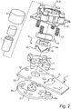
- Figures 2 , 3a and 3b show the right lifting mechanism 5 in Figures 1 a and 1 b without the housing to reveal some of its inner components.
- the left lifting mechanism 5' in Figures 1 a and 1 b is similar to the right one and will therefore not be described in detail.
- the lifting mechanism 5 comprises a motor 6, which is schematically illustrated in Figure 2 .
- the motor 6 is in this case an electric motor, but it is possible to use other types of motors or actuators.
- the motor 6 is mounted to an axle 7.
- the axle 7 is here rigidly mounted to a plate 8 which, in turn, is rigidly mounted to the beam 21 of the towing vehicle 20 shown in Figures 1 a and 1 b.
- the illustrated plate 8 has seats 8a formed by openings in the plate 8 and a protrusion 8b which extends into an elongated hole 3c in the arm 3.
- the seats 8a may be formed by, for example, indentations in the plate 8 instead of openings extending through the plate 8. Further, the seats 8a may form part of the beam 21, or some other structure of the towing vehicle 20, instead of the plate 8. In such case, the plate 8 may be omitted.
- the lifting mechanism 5 further comprises a driver 9 which is rotatable around a driver rotation axis R'.
- the driver 9 has in this case a cylindrical hollow body.
- the driver rotation axis R' is here a central axis of the driver 9.
- the driver rotation axis R' here refers to a geometrical axis.
- the driver rotation axis R' is substantially horizontal when the towing vehicle 20 is standing on horizontal ground.
- a side wall 9a of the driver 9 is substantially parallel with the driver rotation axis R'.
- the side wall 9a is here circular.
- the axle 7 passes through the hollow body of the driver 9 and coincides with the driver rotation axis R'.
- the driver 9 is rotatably mounted to the axle 7.
- the motor 6 is connected to rotate the driver 9 around the driver rotation axis R'. We herein say that the driver 9 moves in a uniform direction when rotating clockwise or counterclockwise around the driver rotation axis R'.
- driver rotation axis R' in this case coincides with the axis of rotation R of the arms 3, 3'.
- the driver rotation axis R' in this case coincides therewith.
- the driver 9 is provided with several slits 9b. More precisely, the illustrated driver 9 has three slits 9b formed in the side wall 9a. The slits 9b passes through the body of the driver 9. Each slit 9b forms a cam surface 9c, so three cam surfaces 9c are in this case formed in the side wall 9a of the driver 9. The cam surfaces 9c and the driver 9 are therefore operatively connected. The cam surfaces 9c are oriented so as to face away from the arm 3. The slits 9b and the cam surfaces 9c are in this case curved. More precisely, the slits 9b and the cam surfaces 9c are V-shaped.
- the driver 9, the slits 9b and the cam surfaces 9c can be implemented in a variety of ways and do not have to be exactly as illustrated in Figure 2 .
- the driver 9 may be solid instead of hollow and the number of slits 9b, as well as the number of cam surfaces 9c, may be smaller or greater than three.
- the cam surfaces 9c do not have to be oriented so as to face away from the arm 3.
- the slits 9b and the cam surfaces 9c are not limited to being V-shaped. Other shapes, such as U-shapes or irregular shapes, are conceivable.
- the cam surfaces 9c may be formed by grooves in the side wall 9a of the driver 9.
- the lifting mechanism 5 further comprises three cam followers 10.
- the number of cam followers 10 is in this case, as is typical, equal to the number of cam surfaces 9c.
- the cam followers 10 are projections extending in a direction substantially perpendicular to the axis R.
- Each cam follower 10 extends into one of the slits 9b, thereby contacting a cam surface 9c.
- each cam follower 10 engages a respective one of the cam surfaces 9c.
- the cam followers 10 are in this case integrated with an annular part 11 which is coaxial with the axis R.
- the annular part 11 here encircles the driver 9.
- the annular part 11 is rotatable about the axis R.
- Four locking members 12 are integrated with the annular part 11.
- the locking members 12 and the cam followers 10 are rigidly connected via the annular part 11. Since the annular part 11 is rotatable about the axis R, the locking members 12 and the cam followers 10 are also rotatable about the axis R.
- the locking members 12 are in this case locking pins extending parallel to the axis R. It should be noted that the locking members 12 do not have to be pins and that the number thereof may be less than or more than four in a different example.
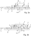
- the locking members 12 have an engaged position (see Figure 3a ) and a disengaged position (see Figure 3b ).
- the locking members 12 move a distance d (see Figure 3b ) parallel to the axis R to get from the engaged position to the disengaged position, and vice versa.
- the distance d may for example be in the centimeter range.
- each locking member 12 engages with a structure of the towing vehicle 20 in such a manner that the arm 3 cannot rotate about the axis R.
- each locking member 12 extends through an opening 3d in the arm 3 and into one of the seats 8a of the plate 8.
- the plate 8 is, as mentioned above, rigidly mounted to the beam 21. The locking members 12 are thus received by the seats 8a when the locking members 12 are in the engaged position.
- the locking members 12 are disengaged from the structure of the towing vehicle 20. Specifically, in this case, the locking members 12 extend into the openings 3d in the arms 3, but not into the seats 8a of the plate 8. Consequently, the locking members 12 can rotate about the axis R, and will then push the arm 3 so that the arm 3, too, rotates about the axis R.
- the lifting mechanism 5 further comprises a biasing arrangement.
- the biasing arrangement comprises a first biasing member 13 and a second biasing member 14.
- a cover 15 of the lifting mechanism 5 acts as an abutment for the first and second biasing members 13, 14.
- the first biasing member 13 here comprises four coil springs. Each coil spring is arranged to bias one of the locking members 12 towards its engaged position by pushing the locking member 12 towards its seat 8a.
- the second biasing member 14 here comprises a wave spring.
- the wave spring 14 is arranged around the driver 9 and to push the annular part 11, during the second phase (further described below), towards the arm 3. Thereby, the second biasing member 14 biases each locking member 12 towards its engaged position.
- the second biasing member 14 has in this case a different spring constant than the first biasing member 13. Specifically, the spring constant of the second biasing member 14 is in this case greater than the spring constant of the first biasing member 13.
- first and second biasing members 13, 14 can be implemented in a variety of ways.
- the first and second biasing members 13, 14 do not have to be springs but could instead be formed by pieces of elastic materials, such as rubber.
- the biasing arrangement may include only one biasing member, so the first biasing member 13 or the second biasing member 14 may be omitted.
- the choice of material for the components of the lifting mechanism 5 vary depending on the application.
- the plate 8, the driver 9 and the locking members 12 are usually made of one or more metals, such as steel, or some other hard and wear-resistant material(s).
- the sizes and dimensions of the components of the lifting mechanism 5 also vary depending on the application.
- the cam surfaces 9c, the cam followers 10 and the annular part 11 may here be seen as forming part of a transmission arrangement.
- the transmission arrangement, the biasing arrangement 13, 14, the driver 9 and the locking members 12 may be seen as forming part of an operating assembly.
- the operating assembly has first points of engagement operatively connected to the locking members 12 and second points of engagement with the arm 3.
- the first points of engagements are in this case between the cam surfaces 9c and the cam followers 10.
- the first points of engagement are here operatively connected to the locking members 12 via the cam followers 10 and the annular part 11.
- the second points of engagement are in this case between the locking members 12 and the arm 3, at the openings 3d in the arm 3.
- the locking members 12 move along the axis R, from their engaged positions to their disengaged positions.
- a person such as the driver of the towing vehicle 20, may raise the bar 2 by starting the motor 6 using for example a control unit (not shown) connected to control the motor 6.
- the control unit may for example include a button or a knob for raising the bar 2 inside the driver's compartment of the towing vehicle 20.
- the motor 6 then rotates the driver 9 around the axis R.
- the cam followers 10 ride on the cam surfaces 9c of the rotating driver 9, whereby the locking members 12 move along the axis R away from the arm 3 while compressing the first biasing member 13 but not the second biasing member 14.
- the locking members 12 are initially in their engaged positions, in which they are received by the seats 8a and, therefore, cannot rotate about the axis R.
- the locking members 12 reach their disengaged positions, in which they are no longer received by the seats 8a.
- the cam surfaces 9c are in this case designed so that the cam followers 10 have not yet reached the points where the two "legs" of the V-shaped cam surfaces 9c meet because that position is typically unstable.
- the cam surfaces 9c may for example be designed so that the cam followers 10 are approximately in the middle of the "legs" when the locking members 12 reach their disengaged positions.
- the continued rotation of the driver 9 causes the locking members 12 to rotate around the axis R.
- the rotating locking members 12 push the arm 3 to rotate until the latter reaches the high position (see Figure 1 b) and cannot be rotated any further.
- the protrusion 8b of the plate 8 moves in the elongated hole 3c of the arm 3 when the arm 3 rotates.
- the arm 3 stops when the protrusion 8b abuts against an end of the elongated hole 3c.
- other types of stopping arrangements for ensuring that the arm 3 stops rotating after having reached the high (or the low) position may be used.
- the locking members 12 rotate around the axis R while engaging the arm 3, thereby rotating the arm 3 from the low position to the high position.
- the locking members 12 rotate around the axis R, instead of translates therealong, because, in the second phase, both the first biasing member 13 and the second biasing member 14 (via the annular part 11) bias the locking members 12.
- the biasing arrangement 13, 14 is in this case adapted to bias the locking members 12 with a larger force in the second phase than in the first phase.
- the biasing arrangement is arranged such that the driver 9 experiences an increase in resistance when rotating, the increase in resistance causing the transition from the first phase to the second phase.
- the translation resistance is greater than the rotation resistance in the second phase.
- this can be achieved by means of a single spring and/or by arranging a protuberance where the two "legs" of the V-shaped cam surfaces 9c meet, so that some extra force is required to move the cam followers 10 from one "leg” to the other.
- This can also be achieved by providing the cam surfaces 9c with several portions that are inclined relative to each other. By providing the cam surfaces 9b with such portions, the cam surfaces 9c may be adapted to cooperate with the biasing arrangement to vary a resistance acting on the driver 9 during the three phases.
- the locking members 12 move along the axis R, from their disengaged positions to their engaged positions. Specifically, when the arm 3 has reached the high position and stopped, the locking members 12 move along the axis R away from the arm 3, compressing both biasing members 13, 14 a bit more, until the cam followers 10 reach the points where the two "legs" of the V-shaped slits 9b meet. The cam followers 10 then continue over to the other "legs", and the locking members 12 start to move towards the arm 3. The locking members 12 are pushed towards the arm 3 by the both biasing members 13, 14 at first and, after a while, only by the first biasing member 13. When the locking members 12 have been received by the seats 8a, they have reached their engaged positions. The arm 3 is now locked and the bar 2 is in the high position.
- FIG. 4 a rear underrun protection device 100 according to a second embodiment of the present invention will be described. It should be noted that the rear underrun protection device 100 in Figure 4 has several features in common with the rear underrun protection device 1 in Figures 1 to 3b , and some of these features will not be discussed, or only briefly discussed, in the following. Moreover, many of the modifications and variations mentioned in the discussion above of the rear underrun protection devices 1 in Figures 1 to 3b are applicable also to the rear underrun protection device 100 in Figure 4 .
- the rear underrun protection device 100 comprises an optional motor 6 which is connected to rotate a driver 9 around a driver rotation axis R', henceforth referred to as the axis R'.
- the driver 9 in Figure 4 is similar to the driver in Figures 2 to 3b .
- the driver 9 in Figure 4 is, however, operatively connected to only one cam surface 9c.
- the cam surface 9c is formed in a V-shaped slit 9b in the side wall 9a of the driver 9.
- the driver 9 is in this case operatively connected to a planetary gear set 101.
- the illustrated planetary gear set 101 is of a conventional type known in the art.
- the planetary gear set 101 is here arranged partly inside the driver 9.
- the planetary gear set 101 here comprises a disc 101 a, a central sun gear 101 b, three intermediate planet gears 101 c and an outer ring gear 101 d.
- the sun gear 101 b is arranged on the axis R'.
- the planet gears 101 c are arranged at a radial distance from the axis R', between the sun gear 101 b and the ring gear 101 d.
- the ring gear 101 d is centered on and rotatable about the axis R'.
- the sun gear 101 b meshes with the planet gears 101 c which mesh with the ring gear 101d.
- the planet gears 101c mesh with inner teeth of the ring gear 101 d.
- the ring gear 101 d has inner teeth, which are arranged on a side of the ring gear 101 d facing the axis R', and outer teeth, which are arranged on a side of the ring gear 101 d facing away from the axis R'.
- the inner teeth and the outer teeth are displaced relative to each other along the axis R'.
- the sun gear 101 b is rotatable about the axis R'.
- the motor 6 is here connected to rotate the sun gear 101 b about the axis R'.
- the motor 6 and the sun gear 101 b are in this case connected via a pin 101 e integrated with the sun gear 101 b.
- the pin 101 e extends through an opening in the driver 9 and connects to the motor 6.
- a bearing (not shown) between the pin 101 e and the driver 9 enables the pin 101 e to rotate relative to the driver 9. It follows that the sun gear 101 b is rotatable relative to the driver 9.
- the planet gears 101 c are movable along a circle centered on the axis R'. Each planet gear 101 c is also rotatable about its central axis R". As can be seen in Figure 4 , each planet gear 101c has in this case a pin 101f integrated therewith. These pins 101f are rotatably attached to the disc 101a which is fixed to the driver 9.
- each planet gear 101 c is rotatable about its central axis R" relative to the driver 9 and (ii) the planet gears 101 c rotate the driver 9 about the axis R' when the planet gears 101 c move along the circle centered on the axis R' (and vice versa).
- the planetary gear set 101 is rotatably attached to an arm 3 for supporting, at a first end portion 3a thereof, an impact bar (not shown).
- the pin 101 e is here rotatably attached to the arm 3 via an attachment 3e.
- the arm 3 is rotatably mounted, at a second end portion 3b thereof, to a plate 8 intended to be mounted to a structure of a towing vehicle.
- the arm 3 is arranged between the plate 8 and the planetary gear set 101.
- the arm 3 is rotatable about an axis of rotation R which in this case is substantially parallel to and spatially separated from the driver rotation axis R'.
- the axis of rotation R of the arm 3 and the driver rotation axis R' do not coincide in this case.
- the axis of rotation R of the arm 3 will henceforth be referred to as the axis R.
- the distance e between the axis R and the axis R' may for example be in the decimeter range.
- the axis R is here substantially parallel to the side wall 9a of the driver 9.
- a gear member 102 is arranged on the same side of the arm 3 as the planetary gear set 101.
- the gear member 102 mesh with the ring gear 101 d. More precisely, the gear member 102 mesh with the outer teeth of the ring gear 101 d.
- the gear member 102 has in this case the shape of a sector of a circle, which is centered on the axis R and the diameter of which is larger than the diameter of the ring wheel 101d.
- the size of the gear member 102 and the size of the ring gear 101 d are chosen based on, for example, the desired transmission ratio.
- the gear member 102 is fixed to the plate 8 via an axle 103.
- the axle 103 is centered on the axis R and passes through an opening in the arm 3.
- a bearing (not shown) enables the arm 3 to rotate relative to the axle 103.
- the arm 3 is thus rotatable relative to the gear member 102.
- the rear underrun protection device 100 further comprises a cam follower 10 which engages the cam surface 9c.
- the cam follower 10 is formed by a projection sticking into the slit 9b.
- the cam follower 10 is in this case integrated with a locking member 104.
- the cam follower 10 and the locking member 104 are therefore operatively connected to each other.
- the locking member 104 is in this case a locking pin.
- the locking member 104 is arranged adjacent to the driver 9.
- the locking member 104 is arranged at a distance from the driver 9 in a direction perpendicular to the axis R.
- the locking member 104 is movable parallel to the axis R between an engaged position and a disengaged position.
- the locking member 104 in this case extends through an opening (not shown) in the arm 3 and engages with a seat (not shown) in the plate 8 so as to prevent the arm 3 from rotating about the axis R.
- the locking member 104 does not engage with the plate 8 and also does not extend through the arm 3. Accordingly, the arm 3 can rotate about the axis R when the locking member 104 is in the disengaged position.
- the rear underrun protection device 100 further comprises a biasing arrangement 105.
- the biasing arrangement 105 is here arranged to bias the locking member 104 towards its engaged position.
- the biasing arrangement 105 illustrated in Figure 4 includes a spring.
- the planetary gear set 101, the cam surface 9c and the cam follower 10 may be seen as forming part of a transmission arrangement.
- the transmission arrangement, the biasing arrangement 105 and the driver 104 may be seen as forming part of an operating assembly.
- the operating assembly has a first point of engagement operatively connected to the locking member 104 and a second point of engagement with the arm 3.
- the first point of engagement is in this case between the cam surface 9c and the cam follower 10.
- the first point of engagement is operatively connected to the locking member 104 via the cam follower 10.
- the second point of engagement is in this case between the pin 101 e and the arm 3, at the attachment 3e.
- the second point of engagement is located along the axis R'.
- the locking member 104 moves parallel to the axis R', from its engaged position to its disengaged position. Specifically, the motor 6 rotates the sun gear 101 b clockwise about the axis R'. There is at this point less resistance to compress the biasing arrangement 105 than to raise the arm 3, and as a result the driver 9 rotates while the ring gear 101d does not. More precisely, the rotation of the sun gear 101 b causes the planet gears 101 c to move clockwise along the circle centered on the axis R', while the ring gear 101 d does not rotate. The rotation of the planet gears 101 c causes the driver 9 to rotate clockwise about the axis R'.
- the cam follower 10 rides on the rotating cam surface 9c, whereby the locking member 104 moves linearly away from the arm 3 while compressing the biasing arrangement 105.
- the resistance to compress the biasing arrangement 105 increases as it is compressed.
- the resistance to compress the biasing arrangement 105 becomes greater than the resistance to rotate the ring gear 101 d.
- the locking member 104 has reached its disengaged position.
- the arm 3 is rotated about the axis R from its low position to its high position.
- the motor 6 continues to rotate the sun gear 101 b clockwise about the axis R'. Since there is now less resistance to rotate the ring gear 101 d than to compress the biasing arrangement 105, the ring gear 101 d rotates while the driver 9 does not. More precisely, the rotation of the sun gear 101 b now causes each planet gear 101 c to rotate counterclockwise about its central axis R". The rotating planet gears 101 c cause the ring gear 101 d to rotate counterclockwise about the axis R'. The rotation of the ring gear 101 d makes it "climb" upwards on the gear member 102.
- the locking member 104 moves parallel to the axis R', from its disengaged position to its engaged position.
- the motor 6 continues to rotate the sun gear 101 b clockwise about the axis R'.
- the ring gear 101d cannot continue to rotate counterclockwise about the axis R', since the arm 3 is in its high position, so the driver 9 now rotates instead of the ring gear 101 d.
- the rotation of the sun gear 101 b causes the planet gears 101 c to move clockwise along the circle centered on the axis R'. This brings the driver 9 to rotate clockwise about the axis R'.
- the cam follower 10 rides on the rotating cam surface 9c, whereby the locking member 104 first moves linearly away from the arm 3, compressing the biasing arrangement 105 a bit further. Then, when the cam follower 10 passes over to the other "leg" of the V-shaped cam surface 9c, the locking member 104 starts to move linearly towards the arm 3. Eventually, the locking member 104 reaches its engaged position and the motor 6 stops. The arm 3 is now locked in its high position.
- FIG. 5 With reference to Figures 5 , 6a, 6b and 6c , a rear underrun protection device 200 according to a third embodiment of the present invention will be described. It should be noted that the rear underrun protection device 200 in Figures 5 to 6c has several features in common with the rear underrun protection devices 1, 100 in Figures 1 to 4 , and some of these features will not be discussed, or only briefly discussed, in the following. Moreover, many of the modifications and variations mentioned in the discussion above of the rear underrun protection devices 1, 100 in Figures 1 to 4 are applicable also to the rear underrun protection device 200 in Figures 5 to 6c .
- the rear underrun protection device 200 comprises two arms which are similar to those of the rear underrun protection devices 1, 100 in Figures 1 to 4 . Only one of the arms is shown in Figure 5 , and that arm is designated by the reference numeral 3.
- the arm 3 has a first end portion 3a where the impact bar (not shown) can be mounted.
- the arm 3 is here rotatably connected to a plate 8 intended to be mounted to a structure of a towing vehicle (not shown).
- the arm 3 is rotatable around an axis of rotation R, henceforth referred to as the axis R.
- the rear underrun protection device 200 further comprises a driver 201 in the form of a linear actuator.
- the driver 201 here comprises a cylinder, such as a hydraulic cylinder or pneumatic cylinder.
- the driver 201 is here arranged on a different side of the arm 3 than the plate 8. As can be seen in Figure 5 , the driver 201 is here elongated and straight.
- a first end portion 201 a of the driver 201 is arranged close to the second end portion 3b of the arm 3.
- the first end portion 201 a of the driver 201 is here pivotably connected at a point which is fixed relative to the plate 8. More specifically, in this case, the first end portion 201 a is pivotably connected to a curved plate 202 which is attached to the plate 8.
- the curved plate 202 is here attached to the plate 8 via a bolt 203 arranged on the axis R.
- the bolt 203 runs through respective holes in the curved plate 203 and the second end portion 3b of the arm 3 which is sandwiched between the plate 8 and the curved plate 202.
- the driver 201 can be pivotably connected at a point which is fixed relative to the plate 8 than the one illustrated in Figure 7 .
- the driver 201 extends from its first end portion 201 a generally towards the first end portion 3a of the arm 3.
- a second end portion 201 b of the driver 201 is pivotably connected to a lever 204.
- the lever 204 is here elongated and straight.
- the second end portion 201 b of the driver 201 is pivotably connected to the lever 204 at a first end portion 204a of the lever 204.
- the driver 201 is in this case extendable and retractable. So the length l 1 of the driver 201 is variable.
- the driver 201 has an extended position and a retracted position.
- the length l 1 of the driver 201 is longer in the extended position than in the retracted position.
- the driver 201 is depicted in the extended position.
- the driver 201 is arranged so as to move substantially parallel to a plane when extending and retracting.
- the rear underrun device 200 here comprises a motor (not shown) arranged to extend and retract the driver 201, but the driver 201 may in a different example be configured to be extended and retracted manually.
- the first and second end portions 201 a, 201 b of the driver 201 perform a linear movement relative to each other.
- the uniform direction is in this case a direction of a linear movement.
- the lever 204 has a second end portion 204b opposite to the first end portion 204a.
- a rod 205 is pivotably connected to the lever 204 at the second end portion 204b.
- the lever 204 is pivotably connected to the arm 3 between the first and second end portions 204a, 204b of the lever 204.
- the connection between the lever 204 and the arm 3 is located between the first and second end portions 3a, 3b of the arm 3.
- the distance between the lever's 204 connection with the driver 201 and the lever's 204 connection with the arm 3 is denoted by l 2 in Figure 5 .
- the distance between the lever's 204 connection with the rod 205 and the lever's 204 connection with the arm 3 is denoted by l 3 in Figure 5 .
- the distance l 3 is here greater than the distance l 2 .
- the rod 205 is in this case elongated and straight. As mentioned above, the rod 205 is pivotably connected to the lever 204. More specifically, a first end portion 205a of the rod 205 is pivotably connected to the second end portion 205b of the lever 204. A second end portion 205b of the rod 205 is pivotably connected to a tiltable member 206.
- the tiltable member 206 is pivotably connected to a housing 207 attached to the arm 3 at the second end portion 3b of the arm 3. In Figure 5 , a part of the housing 207 has been removed in order to show some of the interior of the housing 207. In this case, the tiltable member 206 has three legs 206a, 206b, 206c connected via a connection portion 206d.
- the middle leg 206c is longer than the outer legs 206a, 206b which have the same length.
- the outer legs 206a, 206b are rigidly connected to the connection portion 206d and pivotably connected to the housing 207.
- the legs 206a, 206b, 206c are in this case vertically spaced apart and the rod 205 is pivotably connected to the upper outer leg 206b.
- the tiltable member 206 is connected to a locking member 208 (see the schematic Figures 6a to 6c ), which in this case is a locking pin.
- the locking member 208 is arranged inside the housing 207. More specifically, in this case, an end of the middle leg 206c is pivotably connected to the locking member 208. The other end of the middle leg 206c is pivotably connected to the connection portion 206d.
- the locking member 208 has an engaged position and a disengaged position.
- the engaged and disengaged positions correspond to different positions of the locking member 208 along an axis A.
- a longitudinal extension of the locking member 8 is in this case along the axis A.
- the axis A is substantially parallel to the rotation axis R of the arm 3.
- the locking member 208 is thus movable substantially parallel to the rotation axis R of the arm 3.
- the locking member 208 when in the engaged position, locks the arm 3 by engaging with the plate 8 and, when in the disengaged position, is positioned so that the arm 3 can rotate.
- an angle between the middle leg 206c and the axis A is in this case smaller than an angle between the outer legs 206a, 206b and the axis A.
- the lever 204, rod 205 and tiltable member 206 may be seen as forming part of a transmission arrangement.
- the driver 201 and the transmission arrangement may be seen as forming part of an operating assembly.
- the operating assembly has a first point of engagement operatively connected to the locking member 208 and a second point of engagement with the arm 3.
- the first point of engagement is between the tiltable member 206 and the locking member 208. More precisely, the first point of engagement is between the middle leg 206c and the locking member 208.
- the second point of engagement is between the lever 204 and the arm 3.
- the rear underrun protection 200 may, in a different example, comprise a biasing arrangement arranged such that the driver 201 experiences an increase in resistance when retracting and extending, the increase in resistance causing a transition from the first phase to the second phase (further discussed below).
- a biasing arrangement may for example comprise a spring which is arranged inside the housing 207 and which biases the locking member 208 towards the engaged position.
- the tiltable member 206, housing 207 and/or the locking member 207 may need to be slightly modified to accommodate such a spring.
- the biasing arrangement may include an elastic element, for example an elastic cushion, which is arranged such that the tiltable member 206 must be pushed passed the elastic element when pivoting from one side of the housing 207 to the other.
- an elastic element may for example be arranged at the axis A, a distance from the housing 207.
- the locking member 208 moves from the engaged position in Figure 6a to the disengaged position in Figure 6b . More specifically, the driver 201 retracts and pulls the first end portion 204a of the lever 204 in a direction away from the first end portion 3a of the arm 3. The second end portion 204b of the lever 204 moves towards the first end portion 3a of the arm 3. The rod 205 pulls the tiltable member 206, which causes the locking member 208 to move along the axis A, from the engaged position towards the disengaged position.
- the locking member 208 is in the disengaged position in Figure 6b .
- the arm 3 rotates from the high position to the low position as the driver 201 continues to retract.
- a force to rotate the arm 3 is applied at the connection between the arm 3 and the lever 204.
- the legs 206a, 206b, 206c, 206d of the tiltable member 206 are in this case not aligned with the axis A while the arm 3 rotates. That position is typically more stable than the position where the legs 206a, 206b, 206c, 206d are aligned with the axis A.
- the arm 3 reaches the low position and cannot rotate any further.
- the driver 201 continues to retract.
- the lever 204, the rod 205, the tiltable member 206 and the locking member 208 move instead of the arm 3 since the arm 3 cannot rotate any further.
- the locking member 208 moves from the disengaged position in Figure 6b to the engaged position in Figure 6c .
- the arm 3 is now locked in the low position.
- the driver 201 in this case is arranged to create a linear movement of a first point relative to a second point.
- the first point is located at the first end portion 201 a and stationary relative to the plate 8.
- the second point is here located at the second end portion 201 b and moves together with the arm 3 during the second phase.
- FIG. 7 and 8 a rear underrun protection device 300 according to a fourth embodiment of the present invention will be described.
- the rear underrun protection device in Figures 7 and 8 has many features in common with the rear underrun protection devices 1, 100, 200 in Figures 1 to 6c , and some of these features will not be discussed, or only briefly discussed, in the following.
- many of the modifications and variations mentioned in the discussion above of the rear underrun protection devices 1, 100, 200 in Figures 1 to 6c are applicable also to the rear underrun protection device 300 in Figures 7 and 8 .
- the rear underrun protection device 300 comprises two support arms which are similar to those of the rear underrun protection devices 1, 100, 200 in Figures 1 to 6c .
- One of the two arms is shown in Figure 7 and designated by the reference numeral 3.
- the support arm 3 is rotatably mountable to a towing vehicle (not shown), in this case via a plate 8.
- the rear underrun protection device 300 further comprises a driver 301 arranged to rotate the arm 3.
- the driver 301 in Figures 7 and 8 is a linear actuator.
- the driver 301 is extendable and retractable.
- the driver 301 is arranged so as to move substantially parallel to a plane when extending and retracting.
- a first end portion 301 a of the driver 301 is pivotably connected to the plate 8.
- a second end portion 301 b of the driver 301 is provided with a space 301 c in which a part of a locking member 302, here a locking pin, is received.
- the second end portion 301 b here has a U-like cross section.
- the locking member 302 is movable between an engaged position, in which the locking member 302 locks the arm 3, and a disengaged position, in which the locking member 302 does not lock the arm 3.
- the engaged position and the disengaged position correspond to different positions of the locking member 302 along an axis A.
- the axis A is here substantially parallel to the axis of rotation R of the arm 3.
- the axis of rotation R of the arm 3 points out of the paper in Figure 7 .
- the locking member 302 is in this case operatively connected to a cam follower 303.
- the illustrated cam follower 303 has an elongated shape and is arranged transversely with respect to the longitudinal extension of the locking member 302.
- the cam follower 303 here passes through a hole in the locking member 302.
- the cam follower 303 engages two cam surfaces 301 d operatively connected to the driver 301.
- the cam surfaces 301 d are arranged in the second end portion 301 b of the driver 301 on opposite sides of the space 301 c.
- each cam surface 301 d is arranged in a side wall 301 e of the driver 301.
- the side walls 301 e are here substantially parallel with the axis of rotation R of the arm 3.
- cam surfaces 301 d have the same shape.
- the shape of the cam surfaces 301 d is in this case generally similar to a V.
- each "leg" of the cam surfaces 301 d here comprises two portions that are inclined relative to each other. The purpose of providing the cam surfaces 301 d with such inclined portions was explained in the discussion of the rear underrun protection device 1 in Figures 1a to 3b .
- the rear underrun protection device 300 further comprises an optional biasing arrangement 304.
- the biasing arrangement 304 is here arranged to bias the locking member 302 towards the engaged position.
- the biasing arrangement 304 comprises in this case a spring.
- the spring is slidably arranged between the driver 301 and an end of the locking member 302.
- the cam surface 301 d and the cam follower 303 may be seen as forming part of a transmission arrangement.
- the driver 301, the locking member 302, the biasing arrangement 304 and the transmission arrangement may be seen as forming part of an operating assembly.
- the operating assembly has first points of engagement operatively connected to the locking member 302 and a second point of engagement with the arm 3.
- the first points of engagement are between the cam surfaces 301 d and the cam follower 303.
- the first points of engagement are operatively connected to the locking member 302 via the cam follower 303.
- the second point of engagement is between the locking member 302 and the arm 3.
- the driver 301 extends in the direction D (see Figure 8 ) which is substantially transverse to the axis A.
- the cam follower 303 rides on the cam surface 301d.
- the locking member 302 moves along the axis A (upwards in Figure 8 ), from the engaged position to the disengaged position.
- the driver 301 continues to extend.
- the locking member 302 pushes the arm 3 to rotate from the low position to the high position.
- the cam follower 303 does not move, or moves only a little, along the cam surfaces 301 d during the second phase.
- the driver 301 continues to extend.
- the cam follower 303 rides on the cam surface 301 d, and the locking member 302 moves to the engaged position.
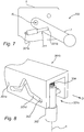
- Figure 9a and 9b show a part of a driver 401 which is a linear actuator.
- the driver 401 is similar to the driver 301 of the rear underrun protection device 300 in Figures 7 and 8 .
- the driver 401 and the locking member 402, here a locking pin are not connected to each other via a cam-and-follower mechanism. Instead, the driver 401 and the locking member 402 are connected via a linking member 403.
- the linking member 403 is pivotably connected to the driver 401 and to the locking member 402.
- the illustrated linking member 403 comprises two side parts 403a and a connecting part 403b connecting the side parts 403a.
- the side parts 403a are pivotably connected to the driver 401 on opposite sides of a space 401 a formed in the driver 401.
- the locking member 402 is arranged so as to be able to move into and out of the space 401 a when the driver 401 extends and retracts.
- the connecting part 401 b is here pivotably connected to the side parts 403a and to the locking member 402. In this case, the connecting part 403b passes through a hole in the locking member 402.
- the connecting part 403b is here arranged transversely with respect to the longitudinal extension of the locking member 402.
- the longitudinal extension of the locking member 402 is in this case along the axis A.
- a biasing arrangement 404 biases the locking member 402 towards the engaged position.
- the biasing arrangement 404 here comprises a spring.
- the locking member 402 is shown in the engaged position in Figures 9a and 9b .
- the disengaged position of the locking member 402 corresponds to an intermediate positon relative to the positions in Figures 9a and 9b . That is to say, the disengaged position of the locking member 402 corresponds to a position where the driver 401 has moved away from the position in Figure 9a by a certain distance in the direction D, but not yet reached the position in Figure 9b .
- the side parts 403a are more aligned with the axis A than in Figures 9a and 9b .
- the side parts 403a may or may not be completely aligned with the axis A when the locking member 402 is in the disengaged position. In either case, however, the disengaged position of the locking member 402 corresponds to a higher position along the axis A in Figures 9a and 9b than the positions shown therein.
- the linking member 403 may be seen as forming part of a transmission arrangement.
- the driver 401, the locking member 402, the biasing arrangement 404 and the transmission arrangement may be seen as forming part of an operating assembly.
- the operating assembly has a first point of engagement operatively connected to the locking member 402 and a second point of engagement with the arm 3.
- the first point of engagement is here between the linking member 403 and the locking member 402. More precisely, the first point of engagement is between the connecting part 403b and the locking member 402.
- the second point of engagement is here between the locking member 402 and the arm 3.
- the driver 401 starts to extend in the direction D (see Figure 9a ).
- the driver 401 is arranged so as to move substantially parallel to a plane when extending (and retracting).
- the linking member 403 moves and pushes the locking member 402 along the axis A (upwards in Figure 9A ), away from the engaged position.
- the locking member 402 In the second phase, the locking member 402 is in the disengaged position.
- the driver 401 continues to extend, thereby causing the locking member 402 to push the arm 3 to rotate.
- the arm 3 cannot be rotated any further and the continued extension of the driver 401 causes the linking member 403 and locking member 402 to move until reaching the positions shown in Figure 9b .
- the locking member 402 has then reached the engaged position and locks the arm 3.
- the rear underrun protection device may have a single motor which drives both arms 3, 3' instead of one motor for each arm 3, 3'.
- the rear underrun protection device may include means for moving the arms 3, 3' manually, such as a handle by which the driver may raise and lower the arms 3, 3'. In such case, the motor(s) may be omitted.
- any reference signs placed between parentheses shall not be construed as limiting to the claim.
- the word “comprising” does not exclude the presence of other elements or steps than those listed in the claim.
- the word “a” or “an” preceding an element does not exclude the presence of a plurality of such elements.
Landscapes
- Engineering & Computer Science (AREA)
- Mechanical Engineering (AREA)
- Body Structure For Vehicles (AREA)
Abstract
Description
- The present invention relates to a rear underrun protection device for a towing vehicle.
- Trucks and other large road vehicles are often equipped with some type of underrun protection device for preventing smaller vehicles from ending up under the truck in the event of a collision. There exist underrun protection devices for frontal, side and rear collisions, an example of the last-mentioned type being disclosed in
WO 2017/130015 . - Rear underrun protection devices usually have a transverse beam which is attached to a rear part of the truck via arms. The arms may be rotatable, thereby allowing the beam to be raised so that a trailer can be connected to the truck. In order to raise or lower the beam, the arms are first unlocked, then rotated and finally locked in the new position. A rather complicated series of movements is thus required to raise or lower the beam, something which makes this process not only time consuming and difficult to perform manually but also complicated to automate using motors.
- It can be seen from the foregoing that there exists a need for a rear underrun protection device which can be raised and lowered more easily than typical prior art devices, preferably one which is robust and inexpensive to manufacture. There also exists a need for a rear underrun protection device, the raising and lowering of which can be motorized in a straightforward manner.
- It would be desirable to provide a rear underrun protection device which at least alleviates the above-discussed needs.
- According to a first aspect of the present invention, there is provided a rear underrun protection device for a towing vehicle, the rear underrun protection device comprising:
- an impact bar intended to be arranged such that a longitudinal extension of the impact bar extends laterally with respect to the towing vehicle;
- two support arms, each arm having a first end portion mounted to the impact bar on different sides of a longitudinal center of the impact bar and a second end portion intended to be rotatably connected to the towing vehicle so that the support arms are rotatable around an axis of rotation;
- at least one locking member configured to move between an engaged position, in which the locking member is intended to engage a structure of the towing vehicle, and a disengaged position, in which the locking member is intended to be disengaged from the towing vehicle, the locking member, when in use and in the engaged position, being adapted to lock one of the support arms in a first position, in which the impact bar is positioned to prevent another vehicle from running under the towing vehicle during a collision, and in a second position, in which the impact bar is positioned to allow a trailer to be connected to the towing vehicle; and
- an operating assembly having a first point of engagement operatively connected to the locking member and a second point of engagement with the one of the support arms, the operating assembly comprising
- a driver movable in a uniform direction and
- a transmission arrangement configured to, upon a uniform movement of the driver:
- in a first phase, move the first point of engagement substantially parallel to the axis of rotation, to move the locking member to its disengaged position;
- in a second phase, move the second point of engagement around the axis rotation, to bring the one of the support arms to rotate between the first and second positions; and
- in a third phase, move the first point of engagement substantially parallel to the axis of rotation, to return the locking member to its engaged position.
- According to a second aspect of the present invention, there is provided a towing vehicle comprising a rear underrun protection device according to the first aspect of the present invention.
- By the term "substantially" is herein meant that the recited characteristic need not be achieved exactly, but that small deviations or variations, for example due to manufacturing tolerances, may occur.
- It is noted that the operating assembly may have more than one first point of engagement and/or more than one second point of engagement. This may for example be the case if the rear underrun protection device has several locking members.
- The inventive concept of the present invention is to, by means of a uniform movement, first unlock the arms, then raise or lower the arms, and finally lock the arms. Thereby, the impact bar can be moved between its different positions by a manoeuvre that is both easy to perform manually and straightforward to automate using a single motor.
- In particular, automation is possible using simple electrical systems. For example, there is a reduced need for a plurality of controllers that help to synchronize the movements of the various components of the rear underrun protection device during raising and lowering of the impact bar.
- Moreover, the above-described rear underrun protection device does not require a large number of components and can have a simple and robust design, so production and maintenance costs can be kept low.
- The operating assembly may be adapted such that the driver experiences an increase in resistance during the uniform movement, the increase in resistance causing the transmission arrangement to transition from the first phase to the second phase. Such an operating member helps to make the transition between the phases fast and well defined.
- The operating assembly may comprise a biasing arrangement adapted to provide the increase in resistance causing the transmission arrangement to transition from the first phase to the second phase. In addition, or alternatively, the biasing arrangement may be adapted to bias the locking member towards the engaged position. Such a biasing arrangement helps to stabilize the movement of the locking member.
- The locking member may be a locking pin movable substantially parallel to the axis of rotation. The locking member may form part of the operating assembly, and the locking member may provide the second point of engagement. Thus, the locking member may be arranged so as to, in the second phase, engage one of the support arms and thereby bring that support arm to rotate. In such case, the rear underrun protection device can have a particularly simple design and a particularly low number of components.
- The locking member may be operatively connected to a cam follower, and the driver may be operatively connected to a cam surface providing the first point of engagement. Such a cam-and-follower mechanism can be simple to manufacture and reliable in operation. The cam surface may have portions that are inclined relative to each other such that the cam surface cooperates with the biasing arrangement to provide the increase in resistance causing the transmission arrangement to transition from the first phase to the second phase. The driver may have a side wall substantially parallel with the axis of rotation, and the cam surface may be formed in the side wall.
- The driver may be rotatable around a driver rotation axis substantially parallel to the axis of rotation. The uniform direction may then be a direction of rotation. The driver rotation axis may coincide with, or be arranged at a distance from, the axis around which the support arms are rotatable.
- The locking member and the cam follower may be integrated with an annular part coaxial with the driver rotation axis. Such a rear underrun protection device can have a particularly small number of components and a particularly simple design. The annular part may rigidly connect several locking members to each other, so that the locking members are movable as a single unit. If the rear underrun protection device has several locking members, the locking members are typically rigidly connected so that all of them move if one of them moves. Of course, the locking members may be rigidly connected to each other in some other way than via the annular part.
- The operating assembly may comprise a ring gear rotatable around the driver rotation axis, wherein the ring gear is engaged with a gear member adapted to be fixed to the structure of the towing vehicle, wherein the ring gear is arranged so that the driver rotation axis moves when the ring gear rotates, and wherein the second point of engagement is located along said driver rotation axis. Such a rear underrun protection device may have a particularly robust design. The ring gear may form part of a planetary gear set connected to move the ring gear in a direction opposite to the rotational movement of the driver.
- The driver may be a linear actuator. The uniform direction may then be a direction of a linear movement. The driver may be arranged to create a linear movement of a first point relative to a second point, the first point being intended to be stationary relative to the structure of the towing vehicle, and the second point being arranged to move together with the one of the support arms during the second phase.
- The rear underrun protection device may comprise at least one motor connected to move the driver in the uniform direction. As mentioned above, the rear underrun protection device according to the first aspect of the present invention is particularly suitable for motorization. The rear underrun protection may alternatively, or additionally, be adapted such that the driver can be moved in the uniform direction manually.
- The rear underrun protection device may comprise two locking members, one for each of the support arms, and two corresponding operating assemblies.
- The present invention will be described in more detail with reference to the appended drawings which show currently preferred embodiments of the invention.
-
Figures 1 a and 1 b show perspective views of a part of a towing vehicle equipped with a rear underrun protection device according to a first embodiment of the present invention. -
Figure 2 shows an exploded view of some components of the rear underrun protection device shown inFigures 1 a and 1 b. -
Figures 3a and 3b show side views of some of the components shown inFigure 2 . -
Figure 4 shows an exploded view of a rear underrun protection device according to a second embodiment of the present invention. -
Figure 5 shows a perspective view of a rear underrun protection device according to a third embodiment of the present invention. -
Figures 6a, 6b and 6c show schematic side views of some components of the rear underrun protection device inFigure 5 . -
Figure 7 shows a schematic side view of a rear underrun protection device according to a fourth embodiment of the present invention. -
Figure 8 shows a schematic perspective view of some components of the rear underrun protection device inFigure 7 . -
Figures 9a and 9b show schematic perspective views of some components of a rear underrun protection device according an embodiment of the present invention. -
Figures 1 a and 1 b show a rear underrun protection device 1 which is mounted to the rear part of a towingvehicle 20. The towingvehicle 20 is in this case is a motorized truck. It should, however, be noted that also an intermediate trailer, i.e. a trailer which is pulled by a motorized truck and which in turn pulls a subsequent trailer, is a towing vehicle in the sense used herein. - The rear underrun protection device 1 comprises an
impact bar 2, henceforth referred to as the "bar" for brevity. In the illustrated example, thebar 2 is elongated and straight, and the transverse cross-section of thebar 2 is circular. In a different example, however, thebar 2 may be curved and/or have a different cross-section, such as a rectangular cross-section. Thebar 2 is arranged so as to be substantially horizontal when the towingvehicle 20 is standing on horizontal ground. The longitudinal extension of thebar 2 is arranged laterally with respect to the towingvehicle 20. Stated differently, thebar 2 is arranged so as to extend substantially transversely to the direction of straight forward travel of the towingvehicle 20. Usually, the length a of thebar 2 is such that thebar 2 extends substantially from one longitudinal side of the towingvehicle 20 to the other. By the longitudinal sides of the towingvehicle 20 is here meant the sides of the towingvehicle 20 that are parallel to the direction of straight forward travel of the towingvehicle 20. This means in practice that the length a of thebar 2 is typically less than 3 m. Thebar 2 is preferably made of a hard material, so that thebar 2 does not easily yield under a force imparted thereon by a vehicle colliding with the towingvehicle 20 from behind. Thebar 2 may for example be made of a metal, such a steel. - The
bar 2 is supported by twosupport arms 3, 3' which will henceforth be referred to as the "arms" for brevity. The illustratedarms 3, 3' are elongated and straight, and botharms 3, 3' have the same shape. However, thearms 3, 3' are not limited to such a shape, and nor do thearms 3, 3' necessarily have to have the same shape. Thearms 3, 3' may for example be curved. Thearms 3, 3' are arranged substantially parallel to each other and to the longitudinal sides of the towingvehicle 20. The distance b between thearms 3, 3' varies depending on the application. The length c of thearms 3, 3' also varies depending on the application, but is typically less than 1 m. Thearms 3, 3' are preferably made of a hard material, so that thearms 3, 3' do not easily yield under a force imparted thereon by a vehicle colliding with the towingvehicle 20 from behind. Thearms 3, 3' may for example be made of steel or some other metal. - As mentioned above, the
arms 3, 3' support thebar 2. Specifically, eacharm 3, 3' has afirst end portion bar 2. Thearms 3, 3' and thebar 2 thus form a rigid structure. Thefirst end portions bar 2 on different sides of the longitudinal center thereof. In this case, thefirst end portions bar 2. Further, in this case, thebar 2 extends beyond thefirst portions vehicle 20. So the distance b between thearms 3, 3' is here less than the length a of thebar 2. More specifically, the distance b is here slightly longer than a third of the length a. - It should be noted that the
bar 2 does not have to be rigidly mounted to thefirst end portions bar 2 is usually mounted so as not to be able to move vertically and horizontally relative to thefirst end portions bar 2 be rotatable around its longitudinal axis, because it is then possible to have the same side of thebar 2 face straight backwards in both the low position and the high position (the low and high positions will be further discussed below). - Each
arm 3, 3' further has asecond end portion second end portions respective beam 21, 21' of the towingvehicle 20. The twobeams 21, 21' extend along the longitudinal sides of the towingvehicle 20 and are arranged on different sides of a longitudinal center line of the towingvehicle 20. It should be noted that, in a different example, the towingvehicle 20 may, instead of thebeams 21, 21' illustrated herein, have some other type of structure to which thesecond end portions - The
second end portions beams 21, 21' such that thearms 3, 3' are movable between a first position (seeFigure 1 a) and a second position (seeFigure 1 b) . Thearms 3, 3' are rotatable around the same axis of rotation R (seeFigures 2 to 3b , further discussed below). The axis of rotation R here refers to a geometrical axis. When thearms 3, 3' are in the first position, thebar 2 is positioned to prevent another vehicle from running under the towingvehicle 20 during a collision. When thearms 3, 3' are in the second position, thebar 2 is positioned to allow a trailer to be connected to acoupling 22 of the towingvehicle 20. In the following, the first position and the second position will be referred to as the low position and the high position, respectively. - The rear underrun protection device 1 further comprises two
optional actuators 4, 4' mechanically connected to arespective arm 3, 3' and to the towingvehicle 20. More precisely, eachactuator 4, 4' is mechanically connected to one of thearms 3, 3' and thebeam 21, 21' to which thatarm 3, 3' is mounted. Theactuators 4, 4' are mechanically connected to a point approximately at the longitudinal center of thearms 3, 3'. Theactuators 4, 4' may, for example, be springs or cylinders, such as hydraulic cylinders or pneumatic cylinders. Thus, the rear underrun protection device 1 may comprise at least oneactuator 4, 4' arranged to help to move thearms 3, 3' between the first position and the second position, the at least oneactuator 4, 4' being connected to one of thearms 3, 3' and connectable to the towingvehicle 20. Theactuators 4, 4' facilitate the raising and the lowering of thebar 2 and, thereby, reduces the load on the liftingmechanisms 5, 5' (further discussed below) so that the wear thereon is reduced. - The rear underrun protection device 1 further comprises two lifting
mechanisms 5, 5' configured to raise and lower thebar 2. Eachlifting mechanism 5, 5' is located at a respective one of thesecond end portions Figures 1 a and 1 b, the liftingmechanisms 5, 5' are illustrated with housings for protection against dirt, water, etc.Figures 2 ,3a and 3b show theright lifting mechanism 5 inFigures 1 a and 1 b without the housing to reveal some of its inner components. The left lifting mechanism 5' inFigures 1 a and 1 b is similar to the right one and will therefore not be described in detail. - The
lifting mechanism 5 comprises amotor 6, which is schematically illustrated inFigure 2 . Themotor 6 is in this case an electric motor, but it is possible to use other types of motors or actuators. Themotor 6 is mounted to anaxle 7. Theaxle 7 is here rigidly mounted to aplate 8 which, in turn, is rigidly mounted to thebeam 21 of the towingvehicle 20 shown inFigures 1 a and 1 b. The illustratedplate 8 hasseats 8a formed by openings in theplate 8 and aprotrusion 8b which extends into anelongated hole 3c in thearm 3. - It should be noted that the
seats 8a may be formed by, for example, indentations in theplate 8 instead of openings extending through theplate 8. Further, theseats 8a may form part of thebeam 21, or some other structure of the towingvehicle 20, instead of theplate 8. In such case, theplate 8 may be omitted. - The
lifting mechanism 5 further comprises adriver 9 which is rotatable around a driver rotation axis R'. Thedriver 9 has in this case a cylindrical hollow body. The driver rotation axis R' is here a central axis of thedriver 9. The driver rotation axis R' here refers to a geometrical axis. The driver rotation axis R' is substantially horizontal when the towingvehicle 20 is standing on horizontal ground. Aside wall 9a of thedriver 9 is substantially parallel with the driver rotation axis R'. Theside wall 9a is here circular. Theaxle 7 passes through the hollow body of thedriver 9 and coincides with the driver rotation axis R'. Thedriver 9 is rotatably mounted to theaxle 7. Themotor 6 is connected to rotate thedriver 9 around the driver rotation axis R'. We herein say that thedriver 9 moves in a uniform direction when rotating clockwise or counterclockwise around the driver rotation axis R'. - It is noted that the driver rotation axis R' in this case coincides with the axis of rotation R of the
arms 3, 3'. In the following, we will refer to the axis of rotation R of thearms 3, 3' as the axis R, for brevity, while keeping in mind that the driver rotation axis R' in this case coincides therewith. - The
driver 9 is provided withseveral slits 9b. More precisely, the illustrateddriver 9 has threeslits 9b formed in theside wall 9a. Theslits 9b passes through the body of thedriver 9. Eachslit 9b forms acam surface 9c, so threecam surfaces 9c are in this case formed in theside wall 9a of thedriver 9. The cam surfaces 9c and thedriver 9 are therefore operatively connected. The cam surfaces 9c are oriented so as to face away from thearm 3. Theslits 9b and the cam surfaces 9c are in this case curved. More precisely, theslits 9b and the cam surfaces 9c are V-shaped. - It should be noted that the
driver 9, theslits 9b and the cam surfaces 9c can be implemented in a variety of ways and do not have to be exactly as illustrated inFigure 2 . For example, thedriver 9 may be solid instead of hollow and the number ofslits 9b, as well as the number of cam surfaces 9c, may be smaller or greater than three. Further, the cam surfaces 9c do not have to be oriented so as to face away from thearm 3. Still further, theslits 9b and the cam surfaces 9c are not limited to being V-shaped. Other shapes, such as U-shapes or irregular shapes, are conceivable. Also, instead of being formed by slits, the cam surfaces 9c may be formed by grooves in theside wall 9a of thedriver 9. - The
lifting mechanism 5 further comprises threecam followers 10. Thus, the number ofcam followers 10 is in this case, as is typical, equal to the number of cam surfaces 9c. In the illustrated example, thecam followers 10 are projections extending in a direction substantially perpendicular to the axis R. Eachcam follower 10 extends into one of theslits 9b, thereby contacting acam surface 9c. Thus, eachcam follower 10 engages a respective one of the cam surfaces 9c. - The
cam followers 10 are in this case integrated with anannular part 11 which is coaxial with the axis R. Theannular part 11 here encircles thedriver 9. Theannular part 11 is rotatable about the axis R.Four locking members 12 are integrated with theannular part 11. The lockingmembers 12 and thecam followers 10 are rigidly connected via theannular part 11. Since theannular part 11 is rotatable about the axis R, the lockingmembers 12 and thecam followers 10 are also rotatable about the axis R. The lockingmembers 12 are in this case locking pins extending parallel to the axis R. It should be noted that the lockingmembers 12 do not have to be pins and that the number thereof may be less than or more than four in a different example. - The locking
members 12 have an engaged position (seeFigure 3a ) and a disengaged position (seeFigure 3b ). The lockingmembers 12 move a distance d (seeFigure 3b ) parallel to the axis R to get from the engaged position to the disengaged position, and vice versa. The distance d may for example be in the centimeter range. - In the engaged position, the locking
members 12 engage with a structure of the towingvehicle 20 in such a manner that thearm 3 cannot rotate about the axis R. Specifically, in this case, each lockingmember 12 extends through anopening 3d in thearm 3 and into one of theseats 8a of theplate 8. Theplate 8 is, as mentioned above, rigidly mounted to thebeam 21. The lockingmembers 12 are thus received by theseats 8a when the lockingmembers 12 are in the engaged position. - In the disengaged position, the locking
members 12 are disengaged from the structure of the towingvehicle 20. Specifically, in this case, the lockingmembers 12 extend into theopenings 3d in thearms 3, but not into theseats 8a of theplate 8. Consequently, the lockingmembers 12 can rotate about the axis R, and will then push thearm 3 so that thearm 3, too, rotates about the axis R. - The
lifting mechanism 5 further comprises a biasing arrangement. In this case, the biasing arrangement comprises a first biasingmember 13 and asecond biasing member 14. Acover 15 of thelifting mechanism 5 acts as an abutment for the first andsecond biasing members first biasing member 13 here comprises four coil springs. Each coil spring is arranged to bias one of the lockingmembers 12 towards its engaged position by pushing the lockingmember 12 towards itsseat 8a. Thesecond biasing member 14 here comprises a wave spring. Thewave spring 14 is arranged around thedriver 9 and to push theannular part 11, during the second phase (further described below), towards thearm 3. Thereby, the second biasingmember 14 biases each lockingmember 12 towards its engaged position. Thesecond biasing member 14 has in this case a different spring constant than the first biasingmember 13. Specifically, the spring constant of the second biasingmember 14 is in this case greater than the spring constant of the first biasingmember 13. - It should be noted that the first and
second biasing members second biasing members member 13 or the second biasingmember 14 may be omitted. - The choice of material for the components of the
lifting mechanism 5 vary depending on the application. Theplate 8, thedriver 9 and the lockingmembers 12 are usually made of one or more metals, such as steel, or some other hard and wear-resistant material(s). The sizes and dimensions of the components of thelifting mechanism 5 also vary depending on the application. - The cam surfaces 9c, the
cam followers 10 and theannular part 11 may here be seen as forming part of a transmission arrangement. The transmission arrangement, the biasingarrangement driver 9 and the lockingmembers 12 may be seen as forming part of an operating assembly. The operating assembly has first points of engagement operatively connected to the lockingmembers 12 and second points of engagement with thearm 3. The first points of engagements are in this case between the cam surfaces 9c and thecam followers 10. The first points of engagement are here operatively connected to the lockingmembers 12 via thecam followers 10 and theannular part 11. The second points of engagement are in this case between the lockingmembers 12 and thearm 3, at theopenings 3d in thearm 3. - The operation of the lifting mechanism in
Figures 2 ,3a and 3b when thebar 2 is raised will now be described with reference to three phases. The operation of thelifting mechanism 5 during lowering of thebar 2 is analogous. Thebar 2 is in this case raised by a rotation of thedriver 9. - In the first phase, the locking
members 12 move along the axis R, from their engaged positions to their disengaged positions. Specifically, assuming that thebar 2 is locked in its low position (seeFigure 1 a) by the lockingmembers 12, a person, such as the driver of the towingvehicle 20, may raise thebar 2 by starting themotor 6 using for example a control unit (not shown) connected to control themotor 6. The control unit may for example include a button or a knob for raising thebar 2 inside the driver's compartment of the towingvehicle 20. Themotor 6 then rotates thedriver 9 around the axis R. Thecam followers 10 ride on the cam surfaces 9c of therotating driver 9, whereby the lockingmembers 12 move along the axis R away from thearm 3 while compressing the first biasingmember 13 but not the second biasingmember 14. The lockingmembers 12 are initially in their engaged positions, in which they are received by theseats 8a and, therefore, cannot rotate about the axis R. Eventually, the lockingmembers 12 reach their disengaged positions, in which they are no longer received by theseats 8a. The cam surfaces 9c are in this case designed so that thecam followers 10 have not yet reached the points where the two "legs" of the V-shaped cam surfaces 9c meet because that position is typically unstable. The cam surfaces 9c may for example be designed so that thecam followers 10 are approximately in the middle of the "legs" when the lockingmembers 12 reach their disengaged positions. - Next, in the second phase, the continued rotation of the
driver 9 causes the lockingmembers 12 to rotate around the axis R. Therotating locking members 12 push thearm 3 to rotate until the latter reaches the high position (seeFigure 1 b) and cannot be rotated any further. In the illustrated example, theprotrusion 8b of theplate 8 moves in theelongated hole 3c of thearm 3 when thearm 3 rotates. Thearm 3 stops when theprotrusion 8b abuts against an end of theelongated hole 3c. Of course, other types of stopping arrangements for ensuring that thearm 3 stops rotating after having reached the high (or the low) position may be used. - Hence, in the second phase, the locking
members 12 rotate around the axis R while engaging thearm 3, thereby rotating thearm 3 from the low position to the high position. The lockingmembers 12 rotate around the axis R, instead of translates therealong, because, in the second phase, both the first biasingmember 13 and the second biasing member 14 (via the annular part 11) bias the lockingmembers 12. This makes the resistance which thelocking members 12 must overcome in order to translate greater than the resistance which they must overcome in order to rotate. Hence, the biasingarrangement members 12 with a larger force in the second phase than in the first phase. Stated differently, the biasing arrangement is arranged such that thedriver 9 experiences an increase in resistance when rotating, the increase in resistance causing the transition from the first phase to the second phase. - It should be noted there are other ways of ensuring that the translation resistance is greater than the rotation resistance in the second phase. For example, this can be achieved by means of a single spring and/or by arranging a protuberance where the two "legs" of the V-shaped cam surfaces 9c meet, so that some extra force is required to move the
cam followers 10 from one "leg" to the other. This can also be achieved by providing the cam surfaces 9c with several portions that are inclined relative to each other. By providing the cam surfaces 9b with such portions, the cam surfaces 9c may be adapted to cooperate with the biasing arrangement to vary a resistance acting on thedriver 9 during the three phases. - In the third phase, the locking
members 12 move along the axis R, from their disengaged positions to their engaged positions. Specifically, when thearm 3 has reached the high position and stopped, the lockingmembers 12 move along the axis R away from thearm 3, compressing both biasingmembers 13, 14 a bit more, until thecam followers 10 reach the points where the two "legs" of the V-shapedslits 9b meet. Thecam followers 10 then continue over to the other "legs", and the lockingmembers 12 start to move towards thearm 3. The lockingmembers 12 are pushed towards thearm 3 by the both biasingmembers member 13. When the lockingmembers 12 have been received by theseats 8a, they have reached their engaged positions. Thearm 3 is now locked and thebar 2 is in the high position. - It can be understood from the foregoing that (i) the first points of engagement move substantially parallel to the axis R during the first and third phases and (ii) the second points of engagement move around the axis R during the second phase.
- With reference to
Figure 4 , a rearunderrun protection device 100 according to a second embodiment of the present invention will be described. It should be noted that the rearunderrun protection device 100 inFigure 4 has several features in common with the rear underrun protection device 1 inFigures 1 to 3b , and some of these features will not be discussed, or only briefly discussed, in the following. Moreover, many of the modifications and variations mentioned in the discussion above of the rear underrun protection devices 1 inFigures 1 to 3b are applicable also to the rearunderrun protection device 100 inFigure 4 . - The rear
underrun protection device 100 comprises anoptional motor 6 which is connected to rotate adriver 9 around a driver rotation axis R', henceforth referred to as the axis R'. Thedriver 9 inFigure 4 is similar to the driver inFigures 2 to 3b . Thedriver 9 inFigure 4 is, however, operatively connected to only onecam surface 9c. Thecam surface 9c is formed in a V-shapedslit 9b in theside wall 9a of thedriver 9. - The
driver 9 is in this case operatively connected to a planetary gear set 101. The illustrated planetary gear set 101 is of a conventional type known in the art. The planetary gear set 101 is here arranged partly inside thedriver 9. The planetary gear set 101 here comprises adisc 101 a, acentral sun gear 101 b, three intermediate planet gears 101 c and anouter ring gear 101 d. Thesun gear 101 b is arranged on the axis R'. The planet gears 101 c are arranged at a radial distance from the axis R', between thesun gear 101 b and thering gear 101 d. Thering gear 101 d is centered on and rotatable about the axis R'. Thesun gear 101 b meshes with the planet gears 101 c which mesh with thering gear 101d. Specifically, the planet gears 101c mesh with inner teeth of thering gear 101 d. As can be seen inFigure 4 , thering gear 101 d has inner teeth, which are arranged on a side of thering gear 101 d facing the axis R', and outer teeth, which are arranged on a side of thering gear 101 d facing away from the axis R'. The inner teeth and the outer teeth are displaced relative to each other along the axis R'. - The
sun gear 101 b is rotatable about the axis R'. Themotor 6 is here connected to rotate thesun gear 101 b about the axis R'. Themotor 6 and thesun gear 101 b are in this case connected via apin 101 e integrated with thesun gear 101 b. Thepin 101 e extends through an opening in thedriver 9 and connects to themotor 6. A bearing (not shown) between thepin 101 e and thedriver 9 enables thepin 101 e to rotate relative to thedriver 9. It follows that thesun gear 101 b is rotatable relative to thedriver 9. - The planet gears 101 c are movable along a circle centered on the axis R'. Each planet gear 101 c is also rotatable about its central axis R". As can be seen in
Figure 4 , each planet gear 101c has in this case a pin 101f integrated therewith. These pins 101f are rotatably attached to thedisc 101a which is fixed to thedriver 9. Thus, the planet gears 101 c are here connected to thedriver 9 in such a manner that (i) each planet gear 101 c is rotatable about its central axis R" relative to thedriver 9 and (ii) the planet gears 101 c rotate thedriver 9 about the axis R' when the planet gears 101 c move along the circle centered on the axis R' (and vice versa). - The planetary gear set 101 is rotatably attached to an
arm 3 for supporting, at afirst end portion 3a thereof, an impact bar (not shown). Specifically, thepin 101 e is here rotatably attached to thearm 3 via anattachment 3e. Thearm 3 is rotatably mounted, at asecond end portion 3b thereof, to aplate 8 intended to be mounted to a structure of a towing vehicle. Thearm 3 is arranged between theplate 8 and the planetary gear set 101. Thearm 3 is rotatable about an axis of rotation R which in this case is substantially parallel to and spatially separated from the driver rotation axis R'. Thus, the axis of rotation R of thearm 3 and the driver rotation axis R' do not coincide in this case. The axis of rotation R of thearm 3 will henceforth be referred to as the axis R. The distance e between the axis R and the axis R' may for example be in the decimeter range. The axis R is here substantially parallel to theside wall 9a of thedriver 9. - A
gear member 102 is arranged on the same side of thearm 3 as the planetary gear set 101. Thegear member 102 mesh with thering gear 101 d. More precisely, thegear member 102 mesh with the outer teeth of thering gear 101 d. Thegear member 102 has in this case the shape of a sector of a circle, which is centered on the axis R and the diameter of which is larger than the diameter of thering wheel 101d. The size of thegear member 102 and the size of thering gear 101 d are chosen based on, for example, the desired transmission ratio. Further, thegear member 102 is fixed to theplate 8 via anaxle 103. Theaxle 103 is centered on the axis R and passes through an opening in thearm 3. A bearing (not shown) enables thearm 3 to rotate relative to theaxle 103. Thearm 3 is thus rotatable relative to thegear member 102. - The rear
underrun protection device 100 further comprises acam follower 10 which engages thecam surface 9c. In this case, thecam follower 10 is formed by a projection sticking into theslit 9b. Thecam follower 10 is in this case integrated with a lockingmember 104. Thecam follower 10 and the lockingmember 104 are therefore operatively connected to each other. The lockingmember 104 is in this case a locking pin. The lockingmember 104 is arranged adjacent to thedriver 9. The lockingmember 104 is arranged at a distance from thedriver 9 in a direction perpendicular to the axis R. The lockingmember 104 is movable parallel to the axis R between an engaged position and a disengaged position. In the engaged position, the lockingmember 104 in this case extends through an opening (not shown) in thearm 3 and engages with a seat (not shown) in theplate 8 so as to prevent thearm 3 from rotating about the axis R. In the disengaged position, the lockingmember 104 does not engage with theplate 8 and also does not extend through thearm 3. Accordingly, thearm 3 can rotate about the axis R when the lockingmember 104 is in the disengaged position. - The rear
underrun protection device 100 further comprises a biasingarrangement 105. The biasingarrangement 105 is here arranged to bias the lockingmember 104 towards its engaged position. The biasingarrangement 105 illustrated inFigure 4 includes a spring. - The planetary gear set 101, the
cam surface 9c and thecam follower 10 may be seen as forming part of a transmission arrangement. The transmission arrangement, the biasingarrangement 105 and thedriver 104 may be seen as forming part of an operating assembly. The operating assembly has a first point of engagement operatively connected to the lockingmember 104 and a second point of engagement with thearm 3. The first point of engagement is in this case between thecam surface 9c and thecam follower 10. The first point of engagement is operatively connected to the lockingmember 104 via thecam follower 10. The second point of engagement is in this case between thepin 101 e and thearm 3, at theattachment 3e. The second point of engagement is located along the axis R'. - The operation of the rear
underride protection device 100 inFigure 4 during raising and lowering of thearm 3 will be described below with reference to three phases. It will be assumed that thearm 3 is initially locked in its low position, and the terms clockwise and counterclockwise are in reference to a view directed along the axis R' towards the left inFigure 4 . - In the first phase, the locking
member 104 moves parallel to the axis R', from its engaged position to its disengaged position. Specifically, themotor 6 rotates thesun gear 101 b clockwise about the axis R'. There is at this point less resistance to compress thebiasing arrangement 105 than to raise thearm 3, and as a result thedriver 9 rotates while thering gear 101d does not. More precisely, the rotation of thesun gear 101 b causes the planet gears 101 c to move clockwise along the circle centered on the axis R', while thering gear 101 d does not rotate. The rotation of the planet gears 101 c causes thedriver 9 to rotate clockwise about the axis R'. Thecam follower 10 rides on the rotatingcam surface 9c, whereby the lockingmember 104 moves linearly away from thearm 3 while compressing the biasingarrangement 105. The resistance to compress thebiasing arrangement 105 increases as it is compressed. Eventually, the resistance to compress thebiasing arrangement 105 becomes greater than the resistance to rotate thering gear 101 d. By then the lockingmember 104 has reached its disengaged position. - In the second phase, the
arm 3 is rotated about the axis R from its low position to its high position. Specifically, themotor 6 continues to rotate thesun gear 101 b clockwise about the axis R'. Since there is now less resistance to rotate thering gear 101 d than to compress thebiasing arrangement 105, thering gear 101 d rotates while thedriver 9 does not. More precisely, the rotation of thesun gear 101 b now causes each planet gear 101 c to rotate counterclockwise about its central axis R". The rotating planet gears 101 c cause thering gear 101 d to rotate counterclockwise about the axis R'. The rotation of thering gear 101 d makes it "climb" upwards on thegear member 102. This brings thearm 3 to rotate counterclockwise about the axis R. Thearm 3 rotates until it reaches the high position, at which point it cannot rotate any further. It is noted that the axis R' moves as thering gear 101 d rotates, in this case along an arc-shaped path. - In the third phase, the locking
member 104 moves parallel to the axis R', from its disengaged position to its engaged position. Specifically, themotor 6 continues to rotate thesun gear 101 b clockwise about the axis R'. Thering gear 101d cannot continue to rotate counterclockwise about the axis R', since thearm 3 is in its high position, so thedriver 9 now rotates instead of thering gear 101 d. More precisely, the rotation of thesun gear 101 b causes the planet gears 101 c to move clockwise along the circle centered on the axis R'. This brings thedriver 9 to rotate clockwise about the axis R'. Thecam follower 10 rides on the rotatingcam surface 9c, whereby the lockingmember 104 first moves linearly away from thearm 3, compressing the biasing arrangement 105 a bit further. Then, when thecam follower 10 passes over to the other "leg" of the V-shapedcam surface 9c, the lockingmember 104 starts to move linearly towards thearm 3. Eventually, the lockingmember 104 reaches its engaged position and themotor 6 stops. Thearm 3 is now locked in its high position. - From the foregoing, it can be understood that (i) the first point of engagement moves, during the first and third phases, substantially parallel to the axis R, and (ii) the second point of engagement moves, during the second phase, around the axis R. Further, it is clear that, in this case, the planetary gear set 101 is connected to rotate the
ring gear 101d in a direction opposite to the rotational movement of thedriver 9, because thering gear 101 d rotates counterclockwise during the second phase while thedriver 9 rotates clockwise during the first and third phases. - With reference to
Figures 5 ,6a, 6b and 6c , a rearunderrun protection device 200 according to a third embodiment of the present invention will be described. It should be noted that the rearunderrun protection device 200 inFigures 5 to 6c has several features in common with the rearunderrun protection devices 1, 100 inFigures 1 to 4 , and some of these features will not be discussed, or only briefly discussed, in the following. Moreover, many of the modifications and variations mentioned in the discussion above of the rearunderrun protection devices 1, 100 inFigures 1 to 4 are applicable also to the rearunderrun protection device 200 inFigures 5 to 6c . - The rear
underrun protection device 200 comprises two arms which are similar to those of the rearunderrun protection devices 1, 100 inFigures 1 to 4 . Only one of the arms is shown inFigure 5 , and that arm is designated by thereference numeral 3. Thearm 3 has afirst end portion 3a where the impact bar (not shown) can be mounted. At asecond end portion 3b, thearm 3 is here rotatably connected to aplate 8 intended to be mounted to a structure of a towing vehicle (not shown). Thearm 3 is rotatable around an axis of rotation R, henceforth referred to as the axis R. - The rear
underrun protection device 200 further comprises adriver 201 in the form of a linear actuator. Thedriver 201 here comprises a cylinder, such as a hydraulic cylinder or pneumatic cylinder. Thedriver 201 is here arranged on a different side of thearm 3 than theplate 8. As can be seen inFigure 5 , thedriver 201 is here elongated and straight. - A first end portion 201 a of the
driver 201 is arranged close to thesecond end portion 3b of thearm 3. The first end portion 201 a of thedriver 201 is here pivotably connected at a point which is fixed relative to theplate 8. More specifically, in this case, the first end portion 201 a is pivotably connected to acurved plate 202 which is attached to theplate 8. Thecurved plate 202 is here attached to theplate 8 via a bolt 203 arranged on the axis R. The bolt 203 runs through respective holes in the curved plate 203 and thesecond end portion 3b of thearm 3 which is sandwiched between theplate 8 and thecurved plate 202. Of course, there are other ways in which thedriver 201 can be pivotably connected at a point which is fixed relative to theplate 8 than the one illustrated inFigure 7 . - The
driver 201 extends from its first end portion 201 a generally towards thefirst end portion 3a of thearm 3. Asecond end portion 201 b of thedriver 201 is pivotably connected to alever 204. Thelever 204 is here elongated and straight. Thesecond end portion 201 b of thedriver 201 is pivotably connected to thelever 204 at afirst end portion 204a of thelever 204. - The
driver 201 is in this case extendable and retractable. So the length l1 of thedriver 201 is variable. Thedriver 201 has an extended position and a retracted position. The length l1 of thedriver 201 is longer in the extended position than in the retracted position. InFigure 5 , thedriver 201 is depicted in the extended position. Thedriver 201 is arranged so as to move substantially parallel to a plane when extending and retracting. Therear underrun device 200 here comprises a motor (not shown) arranged to extend and retract thedriver 201, but thedriver 201 may in a different example be configured to be extended and retracted manually. - When the
driver 201 extends or retracts, the first andsecond end portions 201 a, 201 b of thedriver 201 perform a linear movement relative to each other. We herein say that thedriver 201 moves in a uniform direction when going from the extended position to the retracted position, or vice versa. The uniform direction is in this case a direction of a linear movement. - The
lever 204 has asecond end portion 204b opposite to thefirst end portion 204a. Arod 205 is pivotably connected to thelever 204 at thesecond end portion 204b. Thelever 204 is pivotably connected to thearm 3 between the first andsecond end portions lever 204. The connection between thelever 204 and thearm 3 is located between the first andsecond end portions arm 3. The distance between the lever's 204 connection with thedriver 201 and the lever's 204 connection with thearm 3 is denoted by l2 inFigure 5 . The distance between the lever's 204 connection with therod 205 and the lever's 204 connection with thearm 3 is denoted by l3 inFigure 5 . The distance l3 is here greater than the distance l2. Thereby, when thedriver 201 extends or retracts so that thefirst end portion 204a of thelever 204 moves by a certain amount, thesecond end portion 204b of thelever 204b moves by a greater amount. - The
rod 205 is in this case elongated and straight. As mentioned above, therod 205 is pivotably connected to thelever 204. More specifically, afirst end portion 205a of therod 205 is pivotably connected to thesecond end portion 205b of thelever 204. Asecond end portion 205b of therod 205 is pivotably connected to atiltable member 206. Thetiltable member 206 is pivotably connected to ahousing 207 attached to thearm 3 at thesecond end portion 3b of thearm 3. InFigure 5 , a part of thehousing 207 has been removed in order to show some of the interior of thehousing 207. In this case, thetiltable member 206 has threelegs connection portion 206d. Themiddle leg 206c is longer than theouter legs outer legs connection portion 206d and pivotably connected to thehousing 207. When the rearunderrun protection device 200 is mounted to a towing vehicle standing on horizontal ground, thelegs rod 205 is pivotably connected to the upperouter leg 206b. - The
tiltable member 206 is connected to a locking member 208 (see the schematicFigures 6a to 6c ), which in this case is a locking pin. The lockingmember 208 is arranged inside thehousing 207. More specifically, in this case, an end of themiddle leg 206c is pivotably connected to the lockingmember 208. The other end of themiddle leg 206c is pivotably connected to theconnection portion 206d. - The locking
member 208 has an engaged position and a disengaged position. The engaged and disengaged positions correspond to different positions of the lockingmember 208 along an axis A. A longitudinal extension of the lockingmember 8 is in this case along the axis A. The axis A is substantially parallel to the rotation axis R of thearm 3. The lockingmember 208 is thus movable substantially parallel to the rotation axis R of thearm 3. The lockingmember 208, when in the engaged position, locks thearm 3 by engaging with theplate 8 and, when in the disengaged position, is positioned so that thearm 3 can rotate. As is illustrated inFigures 6a and 6c , when the lockingmember 208 is in the engaged position, an angle between themiddle leg 206c and the axis A is in this case smaller than an angle between theouter legs - The
lever 204,rod 205 andtiltable member 206 may be seen as forming part of a transmission arrangement. Thedriver 201 and the transmission arrangement may be seen as forming part of an operating assembly. The operating assembly has a first point of engagement operatively connected to the lockingmember 208 and a second point of engagement with thearm 3. In this case, the first point of engagement is between thetiltable member 206 and the lockingmember 208. More precisely, the first point of engagement is between themiddle leg 206c and the lockingmember 208. The second point of engagement is between thelever 204 and thearm 3. - It should be noted that the
rear underrun protection 200 may, in a different example, comprise a biasing arrangement arranged such that thedriver 201 experiences an increase in resistance when retracting and extending, the increase in resistance causing a transition from the first phase to the second phase (further discussed below). Such a biasing arrangement may for example comprise a spring which is arranged inside thehousing 207 and which biases the lockingmember 208 towards the engaged position. Of course, thetiltable member 206,housing 207 and/or the lockingmember 207 may need to be slightly modified to accommodate such a spring. As another example, the biasing arrangement may include an elastic element, for example an elastic cushion, which is arranged such that thetiltable member 206 must be pushed passed the elastic element when pivoting from one side of thehousing 207 to the other. Such an elastic element may for example be arranged at the axis A, a distance from thehousing 207. - The operation of the rear
underrun protection device 200 inFigures 5 to 6c during raising and lowering of thearm 3 will be described below with reference to three phases. It should be noted that the rearunderrun protection device 200 inFigure 5 to 6c operates similarly to the rearunderrun protection devices 1, 100 inFigures 1 to 4 , and some of the similarities will not be discussed below, or only briefly discussed. It will be assumed thatdriver 201 is initially in the extended position and that thearm 3 is locked in the high position, as depicted inFigure 5 . - In the first phase, the locking
member 208 moves from the engaged position inFigure 6a to the disengaged position inFigure 6b . More specifically, thedriver 201 retracts and pulls thefirst end portion 204a of thelever 204 in a direction away from thefirst end portion 3a of thearm 3. Thesecond end portion 204b of thelever 204 moves towards thefirst end portion 3a of thearm 3. Therod 205 pulls thetiltable member 206, which causes the lockingmember 208 to move along the axis A, from the engaged position towards the disengaged position. - In the second phase, the locking
member 208 is in the disengaged position inFigure 6b . Thearm 3 rotates from the high position to the low position as thedriver 201 continues to retract. A force to rotate thearm 3 is applied at the connection between thearm 3 and thelever 204. As is illustrated inFigure 6b , thelegs tiltable member 206 are in this case not aligned with the axis A while thearm 3 rotates. That position is typically more stable than the position where thelegs arm 3 reaches the low position and cannot rotate any further. - In the third phase, the
driver 201 continues to retract. Thelever 204, therod 205, thetiltable member 206 and the lockingmember 208 move instead of thearm 3 since thearm 3 cannot rotate any further. The lockingmember 208 moves from the disengaged position inFigure 6b to the engaged position inFigure 6c . Thearm 3 is now locked in the low position. - It can be understood from the foregoing that (i) the first point of engagement moves, during the first and third phases, substantially parallel to the rotation axis R of the
arm 3, and (ii) the second point of engagement moves around the rotation axis R during the second phase. Further, it is clear that thedriver 201 in this case is arranged to create a linear movement of a first point relative to a second point. The first point is located at the first end portion 201 a and stationary relative to theplate 8. The second point is here located at thesecond end portion 201 b and moves together with thearm 3 during the second phase. - With reference to
Figures 7 and 8 , a rearunderrun protection device 300 according to a fourth embodiment of the present invention will be described. It should be noted that the rear underrun protection device inFigures 7 and 8 has many features in common with the rearunderrun protection devices Figures 1 to 6c , and some of these features will not be discussed, or only briefly discussed, in the following. Moreover, many of the modifications and variations mentioned in the discussion above of the rearunderrun protection devices Figures 1 to 6c are applicable also to the rearunderrun protection device 300 inFigures 7 and 8 . - The rear
underrun protection device 300 comprises two support arms which are similar to those of the rearunderrun protection devices Figures 1 to 6c . One of the two arms is shown inFigure 7 and designated by thereference numeral 3. Thesupport arm 3 is rotatably mountable to a towing vehicle (not shown), in this case via aplate 8. - The rear
underrun protection device 300 further comprises adriver 301 arranged to rotate thearm 3. Like thedriver 201 of the rearunderrun protection device 200 inFigures 5 to 6c , thedriver 301 inFigures 7 and 8 is a linear actuator. Thedriver 301 is extendable and retractable. Thedriver 301 is arranged so as to move substantially parallel to a plane when extending and retracting. Afirst end portion 301 a of thedriver 301 is pivotably connected to theplate 8. Asecond end portion 301 b of thedriver 301 is provided with aspace 301 c in which a part of a lockingmember 302, here a locking pin, is received. Thesecond end portion 301 b here has a U-like cross section. The lockingmember 302 is movable between an engaged position, in which the lockingmember 302 locks thearm 3, and a disengaged position, in which the lockingmember 302 does not lock thearm 3. The engaged position and the disengaged position correspond to different positions of the lockingmember 302 along an axis A. The axis A is here substantially parallel to the axis of rotation R of thearm 3. The axis of rotation R of thearm 3 points out of the paper inFigure 7 . - The locking
member 302 is in this case operatively connected to acam follower 303. The illustratedcam follower 303 has an elongated shape and is arranged transversely with respect to the longitudinal extension of the lockingmember 302. Thecam follower 303 here passes through a hole in the lockingmember 302. Thecam follower 303 engages twocam surfaces 301 d operatively connected to thedriver 301. The cam surfaces 301 d are arranged in thesecond end portion 301 b of thedriver 301 on opposite sides of thespace 301 c. Specifically, eachcam surface 301 d is arranged in aside wall 301 e of thedriver 301. Theside walls 301 e are here substantially parallel with the axis of rotation R of thearm 3. Having two such cam surfaces 301 d helps to improve the stability of the movement of thecam follower 303. However, it is conceivable to use a single cam surface. The cam surfaces 301 d have the same shape. The shape of the cam surfaces 301 d is in this case generally similar to a V. As can be seen inFigure 8 , each "leg" of the cam surfaces 301 d here comprises two portions that are inclined relative to each other. The purpose of providing the cam surfaces 301 d with such inclined portions was explained in the discussion of the rear underrun protection device 1 inFigures 1a to 3b . - The rear
underrun protection device 300 further comprises anoptional biasing arrangement 304. The biasingarrangement 304 is here arranged to bias the lockingmember 302 towards the engaged position. The biasingarrangement 304 comprises in this case a spring. The spring is slidably arranged between thedriver 301 and an end of the lockingmember 302. - The
cam surface 301 d and thecam follower 303 may be seen as forming part of a transmission arrangement. Thedriver 301, the lockingmember 302, the biasingarrangement 304 and the transmission arrangement may be seen as forming part of an operating assembly. The operating assembly has first points of engagement operatively connected to the lockingmember 302 and a second point of engagement with thearm 3. In this case, the first points of engagement are between the cam surfaces 301 d and thecam follower 303. The first points of engagement are operatively connected to the lockingmember 302 via thecam follower 303. The second point of engagement is between the lockingmember 302 and thearm 3. - The operation of the rear
underrun protection device 300 inFigures 7 and 8 during raising and lowering of thearm 3 will now be described below with respect to three phases. It should be noted that the rearunderrun protection device 300 inFigures 7 and 8 operates similarly to the rearunderrun protection devices Figures 1 to 6c , and some of the similarities will not be discussed below, or only briefly discussed. For the purpose of the discussion below, it will be assumed that thearm 3 is initially locked in the low position by the lockingmember 302, thedriver 301 is in its retracted position and thecam follower 303 is positioned relative to the cam surfaces 301d as shown inFigure 8 . - In the first phase, the
driver 301 extends in the direction D (seeFigure 8 ) which is substantially transverse to the axis A. Thecam follower 303 rides on thecam surface 301d. The lockingmember 302 moves along the axis A (upwards inFigure 8 ), from the engaged position to the disengaged position. - In the second phase, the
driver 301 continues to extend. The lockingmember 302 pushes thearm 3 to rotate from the low position to the high position. Thecam follower 303 does not move, or moves only a little, along the cam surfaces 301 d during the second phase. - In the third phase, the
driver 301 continues to extend. Thecam follower 303 rides on thecam surface 301 d, and the lockingmember 302 moves to the engaged position. -
Figure 9a and 9b show a part of adriver 401 which is a linear actuator. Thedriver 401 is similar to thedriver 301 of the rearunderrun protection device 300 inFigures 7 and 8 . However, unlike thedriver 301 inFigures 7 and 8 , thedriver 401 and the lockingmember 402, here a locking pin, are not connected to each other via a cam-and-follower mechanism. Instead, thedriver 401 and the lockingmember 402 are connected via a linkingmember 403. The linkingmember 403 is pivotably connected to thedriver 401 and to the lockingmember 402. - The illustrated linking
member 403 comprises twoside parts 403a and a connectingpart 403b connecting theside parts 403a. Theside parts 403a are pivotably connected to thedriver 401 on opposite sides of aspace 401 a formed in thedriver 401. The lockingmember 402 is arranged so as to be able to move into and out of thespace 401 a when thedriver 401 extends and retracts. The connecting part 401 b is here pivotably connected to theside parts 403a and to the lockingmember 402. In this case, the connectingpart 403b passes through a hole in the lockingmember 402. The connectingpart 403b is here arranged transversely with respect to the longitudinal extension of the lockingmember 402. The longitudinal extension of the lockingmember 402 is in this case along the axis A. - A biasing
arrangement 404 biases the lockingmember 402 towards the engaged position. The biasingarrangement 404 here comprises a spring. The lockingmember 402 is shown in the engaged position inFigures 9a and 9b . The disengaged position of the lockingmember 402 corresponds to an intermediate positon relative to the positions inFigures 9a and 9b . That is to say, the disengaged position of the lockingmember 402 corresponds to a position where thedriver 401 has moved away from the position inFigure 9a by a certain distance in the direction D, but not yet reached the position inFigure 9b . When the lockingmember 402 is in the disengaged position, theside parts 403a are more aligned with the axis A than inFigures 9a and 9b . Depending on the application, theside parts 403a may or may not be completely aligned with the axis A when the lockingmember 402 is in the disengaged position. In either case, however, the disengaged position of the lockingmember 402 corresponds to a higher position along the axis A inFigures 9a and 9b than the positions shown therein. - The linking
member 403 may be seen as forming part of a transmission arrangement. Thedriver 401, the lockingmember 402, the biasingarrangement 404 and the transmission arrangement may be seen as forming part of an operating assembly. The operating assembly has a first point of engagement operatively connected to the lockingmember 402 and a second point of engagement with thearm 3. The first point of engagement is here between the linkingmember 403 and the lockingmember 402. More precisely, the first point of engagement is between the connectingpart 403b and the lockingmember 402. The second point of engagement is here between the lockingmember 402 and thearm 3. - It will now be explained how extension and retraction of the
driver 401 moves the lockingmember 402 between its engaged and disengaged positions and raises and lowers thearm 3. It is noted that thedriver 401 inFigures 9a and 9b operates in a manner similar to that of thedriver 301 of the rearunderrun protection device 300 inFigures 7 and 8 . It will be assumed that thedriver 401 and the lockingmember 402 are initially positioned as inFigure 9a . - In the first phase, the
driver 401 starts to extend in the direction D (seeFigure 9a ). Thedriver 401 is arranged so as to move substantially parallel to a plane when extending (and retracting). The linkingmember 403 moves and pushes the lockingmember 402 along the axis A (upwards inFigure 9A ), away from the engaged position. - In the second phase, the locking
member 402 is in the disengaged position. Thedriver 401 continues to extend, thereby causing the lockingmember 402 to push thearm 3 to rotate. - In the third phase, the
arm 3 cannot be rotated any further and the continued extension of thedriver 401 causes the linkingmember 403 and lockingmember 402 to move until reaching the positions shown inFigure 9b . The lockingmember 402 has then reached the engaged position and locks thearm 3. - The person skilled in the art realizes that the present invention by no means is limited to the preferred embodiments described above. On the contrary, many modifications and variations are possible within the scope of the appended claims. For example, although the above-described
bar 2 andarms 3 are separate parts, these components can be formed in one piece. Further, the rear underrun protection device may have a single motor which drives botharms 3, 3' instead of one motor for eacharm 3, 3'. Still further, the rear underrun protection device may include means for moving thearms 3, 3' manually, such as a handle by which the driver may raise and lower thearms 3, 3'. In such case, the motor(s) may be omitted. - In the claims, any reference signs placed between parentheses shall not be construed as limiting to the claim. The word "comprising" does not exclude the presence of other elements or steps than those listed in the claim. The word "a" or "an" preceding an element does not exclude the presence of a plurality of such elements.
Claims (15)
- A rear underrun protection device (1; 100; 200; 300) for a towing vehicle (20), the rear underrun protection device (1; 100; 200; 300) comprising:an impact bar (2) intended to be arranged such that a longitudinal extension of the impact bar (2) extends laterally with respect to the towing vehicle (20);two support arms (3, 3'), each arm (3, 3') having a first end portion (3a, 3a') mounted to the impact bar (2) on different sides of a longitudinal center of the impact bar (2) and a second end portion (3b, 3b') intended to be rotatably connected to the towing vehicle (20) so that the support arms (3, 3') are rotatable around an axis of rotation (R); andat least one locking member (12; 104; 208; 302; 402) configured to move between an engaged position, in which the locking member (12; 104; 208; 302; 402) is intended to engage a structure of the towing vehicle (20), and a disengaged position, in which the locking member (12; 104; 208; 302; 402) is intended to be disengaged from the towing vehicle (20), the locking member (12; 104; 208; 302; 402), when in use and in the engaged position, being adapted to lock one of the support arms (3, 3') in a first position, in which the impact bar (2) is positioned to prevent another vehicle from running under the towing vehicle (20) during a collision, and in a second position, in which the impact bar (2) is positioned to allow a trailer to be connected to the towing vehicle (20),characterized byan operating assembly having a first point of engagement operatively connected to the locking member (12; 104; 208; 302; 402) and a second point of engagement with said one of the support arms (3, 3'), the operating assembly comprisinga driver (9; 201; 301; 401) movable in a uniform direction anda transmission arrangement configured to, upon a uniform movement of the driver (9; 201; 301; 401):in a first phase, move the first point of engagement substantially parallel to said axis of rotation (R), to move the locking member (12; 104; 208; 302; 402) to its disengaged position;in a second phase, move the second point of engagement around said axis of rotation (R), to bring said one of the support arms (3, 3') to rotate between said first and second positions; andin a third phase, move the first point of engagement substantially parallel to said axis of rotation (R), to return the locking member (12; 104; 208; 302; 402) to its engaged position.
- The rear underrun protection device (1; 100; 200; 300) according to claim 1, wherein the operating assembly is adapted such that the driver (9; 201; 301; 401) experiences an increase in resistance during said uniform movement, the increase in resistance causing the transmission arrangement to transition from the first phase to the second phase.
- The rear underrun protection device (1; 100; 200; 300) according to claim 1 or 2, wherein the operating assembly comprises a biasing arrangement (13, 14; 105; 304; 404) adapted to bias the locking member (12; 104; 208; 302; 402) towards the engaged position.
- The rear underrun protection device (1; 100; 200; 300) according to any of the preceding claims, wherein the locking member (12; 104; 208; 302; 402) is a locking pin movable substantially parallel to said axis of rotation (R).
- The rear underrun protection device (1; 300) according to any of the preceding claims, wherein the locking member (12; 302; 402) forms part of the operating assembly, and the locking member (12; 302; 402) provides the second point of engagement.
- The rear underrun protection device (1; 100; 300) according to anyone of the preceding claims, wherein the locking member (12; 104; 302) is operatively connected to a cam follower (10; 303), and the driver (9; 301) is operatively connected to a cam surface (9c; 301 d) providing the first point of engagement.
- The rear underrun protection device (300) according to claims 3 and 6, wherein the cam surface (301d) has portions which are inclined relative to each other such that the cam surface (301 d) cooperates with the biasing arrangement (304) to provide said increase in resistance.
- The rear underrun protection device (1; 100; 300) according to claim 6 or 7, wherein the driver (9; 301) has a side wall (9a; 301 e) substantially parallel with said axis of rotation (R), and the cam surface (9c; 301 d) is formed in the side wall (9a; 301 e).
- The rear underrun protection device (1; 100) according to any one of the preceding claims, wherein the driver (9) is rotatable around a driver rotation axis (R') substantially parallel to said axis of rotation (R).
- The rear underrun protection device (1) according to claim 9, wherein the locking member (12) and the cam follower (10) are integrated with an annular part (11) coaxial with said driver rotation axis (R').
- The rear underrun protection device (100) according to claim 9, wherein the operating assembly comprises a ring gear (101 d) rotatable around said driver rotation axis (R'), wherein the ring gear (101 d) is engaged with a gear member (102) adapted to be fixed to said structure of the towing vehicle (20), wherein the ring gear (101d) is arranged so that said driver rotation axis (R') moves when the ring gear (101 d) rotates, and wherein the second point of engagement is located along said driver rotation axis (R').
- The rear underrun protection device (100) according to claim 11, wherein the ring gear (101 d) forms part of a planetary gear set (101) connected to move the ring gear (101d) in a direction opposite to the rotational movement of the driver (9).
- The rear underrun protection device (200; 300) according to any one of the claims 1 to 8, wherein the driver (201; 301; 401) is a linear actuator.
- The rear underrun protection device (200; 300) according to claim 13, wherein the driver (201; 301; 401) is arranged to create a linear movement of a first point relative to a second point, the first point being intended to be stationary relative to said structure of the towing vehicle, and the second point being arranged to move together with said one of the support arms during the second phase.
- A towing vehicle (20) comprising a rear underrun protection device (1; 100; 200; 300) according to any one of the preceding claims.
Priority Applications (4)
| Application Number | Priority Date | Filing Date | Title |
|---|---|---|---|
| EP18164241.4A EP3546296B1 (en) | 2018-03-27 | 2018-03-27 | A rear underrun protection device |
| PL18164241T PL3546296T3 (en) | 2018-03-27 | 2018-03-27 | A rear underrun protection device |
| CN201980029626.6A CN112118986B (en) | 2018-03-27 | 2019-03-26 | Rear underbody guard |
| PCT/EP2019/057565 WO2019185618A1 (en) | 2018-03-27 | 2019-03-26 | A rear underrun protection device |
Applications Claiming Priority (1)
| Application Number | Priority Date | Filing Date | Title |
|---|---|---|---|
| EP18164241.4A EP3546296B1 (en) | 2018-03-27 | 2018-03-27 | A rear underrun protection device |
Publications (2)
| Publication Number | Publication Date |
|---|---|
| EP3546296A1 true EP3546296A1 (en) | 2019-10-02 |
| EP3546296B1 EP3546296B1 (en) | 2020-09-23 |
Family
ID=61827599
Family Applications (1)
| Application Number | Title | Priority Date | Filing Date |
|---|---|---|---|
| EP18164241.4A Active EP3546296B1 (en) | 2018-03-27 | 2018-03-27 | A rear underrun protection device |
Country Status (4)
| Country | Link |
|---|---|
| EP (1) | EP3546296B1 (en) |
| CN (1) | CN112118986B (en) |
| PL (1) | PL3546296T3 (en) |
| WO (1) | WO2019185618A1 (en) |
Families Citing this family (1)
| Publication number | Priority date | Publication date | Assignee | Title |
|---|---|---|---|---|
| EP4094998B1 (en) * | 2021-05-27 | 2024-07-17 | Fahrzeugbau KEMPF GmbH | Underride protection for vehicles with tiltable loading platform |
Citations (5)
| Publication number | Priority date | Publication date | Assignee | Title |
|---|---|---|---|---|
| DE19928104A1 (en) * | 1999-06-19 | 2000-12-28 | Daimler Chrysler Ag | Commercial vehicle drop-down drive-under protection device has lever arms and guide mechanism for movement of rear bumper bar between raised and lowered positions |
| WO2003055723A1 (en) * | 2001-12-21 | 2003-07-10 | Volvo Lastvagnar Ab | Underrun protection device |
| EP3064403A1 (en) * | 2015-03-02 | 2016-09-07 | Franz Xaver Meiller Fahrzeug- und Maschinenfabrik-GmbH & Co KG | Underride barrier with an adjustable stop |
| EP3088257A1 (en) * | 2015-04-28 | 2016-11-02 | Franz Xaver Meiller Fahrzeug- und Maschinenfabrik-GmbH & Co. KG | Underride barrier having adjustment apparatus and vehicle comprising such an underride barrier |
| WO2017130015A1 (en) | 2016-01-28 | 2017-08-03 | Volvo Truck Corporation | Foldable rear underrun protection arrangement |
Family Cites Families (2)
| Publication number | Priority date | Publication date | Assignee | Title |
|---|---|---|---|---|
| US8246091B1 (en) * | 2011-08-10 | 2012-08-21 | Ford Global Technologies, Llc | Inertia-locking reactive bumper for motor vehicle |
| US8949153B2 (en) * | 2013-01-11 | 2015-02-03 | GM Global Technology Operations LLC | Energy absorbing shield and system for small urban vehicles |
-
2018
- 2018-03-27 EP EP18164241.4A patent/EP3546296B1/en active Active
- 2018-03-27 PL PL18164241T patent/PL3546296T3/en unknown
-
2019
- 2019-03-26 WO PCT/EP2019/057565 patent/WO2019185618A1/en not_active Ceased
- 2019-03-26 CN CN201980029626.6A patent/CN112118986B/en active Active
Patent Citations (5)
| Publication number | Priority date | Publication date | Assignee | Title |
|---|---|---|---|---|
| DE19928104A1 (en) * | 1999-06-19 | 2000-12-28 | Daimler Chrysler Ag | Commercial vehicle drop-down drive-under protection device has lever arms and guide mechanism for movement of rear bumper bar between raised and lowered positions |
| WO2003055723A1 (en) * | 2001-12-21 | 2003-07-10 | Volvo Lastvagnar Ab | Underrun protection device |
| EP3064403A1 (en) * | 2015-03-02 | 2016-09-07 | Franz Xaver Meiller Fahrzeug- und Maschinenfabrik-GmbH & Co KG | Underride barrier with an adjustable stop |
| EP3088257A1 (en) * | 2015-04-28 | 2016-11-02 | Franz Xaver Meiller Fahrzeug- und Maschinenfabrik-GmbH & Co. KG | Underride barrier having adjustment apparatus and vehicle comprising such an underride barrier |
| WO2017130015A1 (en) | 2016-01-28 | 2017-08-03 | Volvo Truck Corporation | Foldable rear underrun protection arrangement |
Also Published As
| Publication number | Publication date |
|---|---|
| WO2019185618A1 (en) | 2019-10-03 |
| CN112118986B (en) | 2024-06-28 |
| EP3546296B1 (en) | 2020-09-23 |
| PL3546296T3 (en) | 2021-03-08 |
| CN112118986A (en) | 2020-12-22 |
Similar Documents
| Publication | Publication Date | Title |
|---|---|---|
| EP1927504B1 (en) | Central arm rest with parallel adjustment functions | |
| DE3639377C2 (en) | ||
| EP1533149B1 (en) | Trailer hitch for vehicles | |
| EP1836085B1 (en) | Servodrive for a trailer | |
| EP1628853A1 (en) | Crash-active headrest | |
| EP1880879B1 (en) | Pivotable towing device for traction vehicles | |
| AT4127U1 (en) | ELECTRICALLY OPERABLE JOINT DRIVE FOR AN EXTERNAL MIRROR | |
| EP0854063B1 (en) | Device for locking tiltable split backrests on motor vehicle rear seats | |
| EP3904128B1 (en) | Trailer coupling | |
| DE69100385T2 (en) | Planet-free, continuous joint with play compensation. | |
| EP2704921A1 (en) | Fitting system for a vehicle seat | |
| DE102007025327A1 (en) | Vehicle seat assembly | |
| EP3546296B1 (en) | A rear underrun protection device | |
| DE2838361A1 (en) | VEHICLE SEAT | |
| WO2020120194A1 (en) | Vehicle seat having an adjustment device and motor vehicle having such a vehicle seat | |
| WO2020078504A1 (en) | Lifting device for rotationally moving a motor vehicle | |
| DE102012222983B4 (en) | Swiveling armrest, especially center armrest for a motor vehicle | |
| EP3662123B1 (en) | Motor lock | |
| DE202011100689U1 (en) | vehicle seat | |
| DE10104386A1 (en) | Automotive headrest for front seat with automated lower or lift system activated by forward or rearward seat back tilt action | |
| EP1522470B1 (en) | Rollover protection system for vehicles comprising a deployable arch combined with a headrest | |
| EP1785295B1 (en) | Adjustable stabilizer bar | |
| DE202010017832U1 (en) | Auxiliary drive unit for a trailer | |
| WO2006092210A2 (en) | Motor vehicle | |
| CN117048453B (en) | A type of seat and car |
Legal Events
| Date | Code | Title | Description |
|---|---|---|---|
| PUAI | Public reference made under article 153(3) epc to a published international application that has entered the european phase |
Free format text: ORIGINAL CODE: 0009012 |
|
| STAA | Information on the status of an ep patent application or granted ep patent |
Free format text: STATUS: THE APPLICATION HAS BEEN PUBLISHED |
|
| AK | Designated contracting states |
Kind code of ref document: A1 Designated state(s): AL AT BE BG CH CY CZ DE DK EE ES FI FR GB GR HR HU IE IS IT LI LT LU LV MC MK MT NL NO PL PT RO RS SE SI SK SM TR |
|
| AX | Request for extension of the european patent |
Extension state: BA ME |
|
| STAA | Information on the status of an ep patent application or granted ep patent |
Free format text: STATUS: REQUEST FOR EXAMINATION WAS MADE |
|
| 17P | Request for examination filed |
Effective date: 20200206 |
|
| RBV | Designated contracting states (corrected) |
Designated state(s): AL AT BE BG CH CY CZ DE DK EE ES FI FR GB GR HR HU IE IS IT LI LT LU LV MC MK MT NL NO PL PT RO RS SE SI SK SM TR |
|
| GRAP | Despatch of communication of intention to grant a patent |
Free format text: ORIGINAL CODE: EPIDOSNIGR1 |
|
| STAA | Information on the status of an ep patent application or granted ep patent |
Free format text: STATUS: GRANT OF PATENT IS INTENDED |
|
| INTG | Intention to grant announced |
Effective date: 20200417 |
|
| GRAS | Grant fee paid |
Free format text: ORIGINAL CODE: EPIDOSNIGR3 |
|
| GRAA | (expected) grant |
Free format text: ORIGINAL CODE: 0009210 |
|
| STAA | Information on the status of an ep patent application or granted ep patent |
Free format text: STATUS: THE PATENT HAS BEEN GRANTED |
|
| AK | Designated contracting states |
Kind code of ref document: B1 Designated state(s): AL AT BE BG CH CY CZ DE DK EE ES FI FR GB GR HR HU IE IS IT LI LT LU LV MC MK MT NL NO PL PT RO RS SE SI SK SM TR |
|
| REG | Reference to a national code |
Ref country code: GB Ref legal event code: FG4D |
|
| REG | Reference to a national code |
Ref country code: CH Ref legal event code: EP |
|
| REG | Reference to a national code |
Ref country code: IE Ref legal event code: FG4D |
|
| REG | Reference to a national code |
Ref country code: DE Ref legal event code: R096 Ref document number: 602018007979 Country of ref document: DE Ref country code: AT Ref legal event code: REF Ref document number: 1316082 Country of ref document: AT Kind code of ref document: T Effective date: 20201015 |
|
| REG | Reference to a national code |
Ref country code: FI Ref legal event code: FGE |
|
| REG | Reference to a national code |
Ref country code: SE Ref legal event code: TRGR |
|
| PG25 | Lapsed in a contracting state [announced via postgrant information from national office to epo] |
Ref country code: HR Free format text: LAPSE BECAUSE OF FAILURE TO SUBMIT A TRANSLATION OF THE DESCRIPTION OR TO PAY THE FEE WITHIN THE PRESCRIBED TIME-LIMIT Effective date: 20200923 Ref country code: BG Free format text: LAPSE BECAUSE OF FAILURE TO SUBMIT A TRANSLATION OF THE DESCRIPTION OR TO PAY THE FEE WITHIN THE PRESCRIBED TIME-LIMIT Effective date: 20201223 Ref country code: NO Free format text: LAPSE BECAUSE OF FAILURE TO SUBMIT A TRANSLATION OF THE DESCRIPTION OR TO PAY THE FEE WITHIN THE PRESCRIBED TIME-LIMIT Effective date: 20201223 Ref country code: GR Free format text: LAPSE BECAUSE OF FAILURE TO SUBMIT A TRANSLATION OF THE DESCRIPTION OR TO PAY THE FEE WITHIN THE PRESCRIBED TIME-LIMIT Effective date: 20201224 |
|
| REG | Reference to a national code |
Ref country code: AT Ref legal event code: MK05 Ref document number: 1316082 Country of ref document: AT Kind code of ref document: T Effective date: 20200923 |
|
| PG25 | Lapsed in a contracting state [announced via postgrant information from national office to epo] |
Ref country code: LV Free format text: LAPSE BECAUSE OF FAILURE TO SUBMIT A TRANSLATION OF THE DESCRIPTION OR TO PAY THE FEE WITHIN THE PRESCRIBED TIME-LIMIT Effective date: 20200923 Ref country code: RS Free format text: LAPSE BECAUSE OF FAILURE TO SUBMIT A TRANSLATION OF THE DESCRIPTION OR TO PAY THE FEE WITHIN THE PRESCRIBED TIME-LIMIT Effective date: 20200923 |
|
| REG | Reference to a national code |
Ref country code: NL Ref legal event code: MP Effective date: 20200923 |
|
| REG | Reference to a national code |
Ref country code: LT Ref legal event code: MG4D |
|
| PG25 | Lapsed in a contracting state [announced via postgrant information from national office to epo] |
Ref country code: EE Free format text: LAPSE BECAUSE OF FAILURE TO SUBMIT A TRANSLATION OF THE DESCRIPTION OR TO PAY THE FEE WITHIN THE PRESCRIBED TIME-LIMIT Effective date: 20200923 Ref country code: PT Free format text: LAPSE BECAUSE OF FAILURE TO SUBMIT A TRANSLATION OF THE DESCRIPTION OR TO PAY THE FEE WITHIN THE PRESCRIBED TIME-LIMIT Effective date: 20210125 Ref country code: RO Free format text: LAPSE BECAUSE OF FAILURE TO SUBMIT A TRANSLATION OF THE DESCRIPTION OR TO PAY THE FEE WITHIN THE PRESCRIBED TIME-LIMIT Effective date: 20200923 Ref country code: CZ Free format text: LAPSE BECAUSE OF FAILURE TO SUBMIT A TRANSLATION OF THE DESCRIPTION OR TO PAY THE FEE WITHIN THE PRESCRIBED TIME-LIMIT Effective date: 20200923 Ref country code: LT Free format text: LAPSE BECAUSE OF FAILURE TO SUBMIT A TRANSLATION OF THE DESCRIPTION OR TO PAY THE FEE WITHIN THE PRESCRIBED TIME-LIMIT Effective date: 20200923 Ref country code: SM Free format text: LAPSE BECAUSE OF FAILURE TO SUBMIT A TRANSLATION OF THE DESCRIPTION OR TO PAY THE FEE WITHIN THE PRESCRIBED TIME-LIMIT Effective date: 20200923 |
|
| PG25 | Lapsed in a contracting state [announced via postgrant information from national office to epo] |
Ref country code: IS Free format text: LAPSE BECAUSE OF FAILURE TO SUBMIT A TRANSLATION OF THE DESCRIPTION OR TO PAY THE FEE WITHIN THE PRESCRIBED TIME-LIMIT Effective date: 20210123 Ref country code: AL Free format text: LAPSE BECAUSE OF FAILURE TO SUBMIT A TRANSLATION OF THE DESCRIPTION OR TO PAY THE FEE WITHIN THE PRESCRIBED TIME-LIMIT Effective date: 20200923 Ref country code: AT Free format text: LAPSE BECAUSE OF FAILURE TO SUBMIT A TRANSLATION OF THE DESCRIPTION OR TO PAY THE FEE WITHIN THE PRESCRIBED TIME-LIMIT Effective date: 20200923 Ref country code: ES Free format text: LAPSE BECAUSE OF FAILURE TO SUBMIT A TRANSLATION OF THE DESCRIPTION OR TO PAY THE FEE WITHIN THE PRESCRIBED TIME-LIMIT Effective date: 20200923 |
|
| REG | Reference to a national code |
Ref country code: DE Ref legal event code: R097 Ref document number: 602018007979 Country of ref document: DE |
|
| PG25 | Lapsed in a contracting state [announced via postgrant information from national office to epo] |
Ref country code: SK Free format text: LAPSE BECAUSE OF FAILURE TO SUBMIT A TRANSLATION OF THE DESCRIPTION OR TO PAY THE FEE WITHIN THE PRESCRIBED TIME-LIMIT Effective date: 20200923 |
|
| PLBE | No opposition filed within time limit |
Free format text: ORIGINAL CODE: 0009261 |
|
| STAA | Information on the status of an ep patent application or granted ep patent |
Free format text: STATUS: NO OPPOSITION FILED WITHIN TIME LIMIT |
|
| PG25 | Lapsed in a contracting state [announced via postgrant information from national office to epo] |
Ref country code: SI Free format text: LAPSE BECAUSE OF FAILURE TO SUBMIT A TRANSLATION OF THE DESCRIPTION OR TO PAY THE FEE WITHIN THE PRESCRIBED TIME-LIMIT Effective date: 20200923 Ref country code: DK Free format text: LAPSE BECAUSE OF FAILURE TO SUBMIT A TRANSLATION OF THE DESCRIPTION OR TO PAY THE FEE WITHIN THE PRESCRIBED TIME-LIMIT Effective date: 20200923 |
|
| 26N | No opposition filed |
Effective date: 20210624 |
|
| PG25 | Lapsed in a contracting state [announced via postgrant information from national office to epo] |
Ref country code: MC Free format text: LAPSE BECAUSE OF FAILURE TO SUBMIT A TRANSLATION OF THE DESCRIPTION OR TO PAY THE FEE WITHIN THE PRESCRIBED TIME-LIMIT Effective date: 20200923 |
|
| REG | Reference to a national code |
Ref country code: CH Ref legal event code: PL |
|
| REG | Reference to a national code |
Ref country code: BE Ref legal event code: MM Effective date: 20210331 |
|
| PG25 | Lapsed in a contracting state [announced via postgrant information from national office to epo] |
Ref country code: FR Free format text: LAPSE BECAUSE OF NON-PAYMENT OF DUE FEES Effective date: 20210331 Ref country code: LI Free format text: LAPSE BECAUSE OF NON-PAYMENT OF DUE FEES Effective date: 20210331 Ref country code: LU Free format text: LAPSE BECAUSE OF NON-PAYMENT OF DUE FEES Effective date: 20210327 Ref country code: IE Free format text: LAPSE BECAUSE OF NON-PAYMENT OF DUE FEES Effective date: 20210327 Ref country code: CH Free format text: LAPSE BECAUSE OF NON-PAYMENT OF DUE FEES Effective date: 20210331 |
|
| PG25 | Lapsed in a contracting state [announced via postgrant information from national office to epo] |
Ref country code: BE Free format text: LAPSE BECAUSE OF NON-PAYMENT OF DUE FEES Effective date: 20210331 |
|
| PG25 | Lapsed in a contracting state [announced via postgrant information from national office to epo] |
Ref country code: NL Free format text: LAPSE BECAUSE OF NON-PAYMENT OF DUE FEES Effective date: 20200923 Ref country code: CY Free format text: LAPSE BECAUSE OF FAILURE TO SUBMIT A TRANSLATION OF THE DESCRIPTION OR TO PAY THE FEE WITHIN THE PRESCRIBED TIME-LIMIT Effective date: 20200923 |
|
| PG25 | Lapsed in a contracting state [announced via postgrant information from national office to epo] |
Ref country code: HU Free format text: LAPSE BECAUSE OF FAILURE TO SUBMIT A TRANSLATION OF THE DESCRIPTION OR TO PAY THE FEE WITHIN THE PRESCRIBED TIME-LIMIT; INVALID AB INITIO Effective date: 20180327 |
|
| PG25 | Lapsed in a contracting state [announced via postgrant information from national office to epo] |
Ref country code: MK Free format text: LAPSE BECAUSE OF FAILURE TO SUBMIT A TRANSLATION OF THE DESCRIPTION OR TO PAY THE FEE WITHIN THE PRESCRIBED TIME-LIMIT Effective date: 20200923 |
|
| PG25 | Lapsed in a contracting state [announced via postgrant information from national office to epo] |
Ref country code: MT Free format text: LAPSE BECAUSE OF FAILURE TO SUBMIT A TRANSLATION OF THE DESCRIPTION OR TO PAY THE FEE WITHIN THE PRESCRIBED TIME-LIMIT Effective date: 20200923 |
|
| PG25 | Lapsed in a contracting state [announced via postgrant information from national office to epo] |
Ref country code: TR Free format text: LAPSE BECAUSE OF FAILURE TO SUBMIT A TRANSLATION OF THE DESCRIPTION OR TO PAY THE FEE WITHIN THE PRESCRIBED TIME-LIMIT Effective date: 20200923 |
|
| PGFP | Annual fee paid to national office [announced via postgrant information from national office to epo] |
Ref country code: FI Payment date: 20251218 Year of fee payment: 9 |
|
| PGFP | Annual fee paid to national office [announced via postgrant information from national office to epo] |
Ref country code: SE Payment date: 20260212 Year of fee payment: 9 |
|
| PGFP | Annual fee paid to national office [announced via postgrant information from national office to epo] |
Ref country code: GB Payment date: 20260213 Year of fee payment: 9 |
|
| PGFP | Annual fee paid to national office [announced via postgrant information from national office to epo] |
Ref country code: DE Payment date: 20260216 Year of fee payment: 9 |
|
| PGFP | Annual fee paid to national office [announced via postgrant information from national office to epo] |
Ref country code: IT Payment date: 20260126 Year of fee payment: 9 |
|
| PGFP | Annual fee paid to national office [announced via postgrant information from national office to epo] |
Ref country code: PL Payment date: 20260108 Year of fee payment: 9 |