EP3546295B1 - Energieabsorberelement für ein kraftfahrzeug - Google Patents
Energieabsorberelement für ein kraftfahrzeug Download PDFInfo
- Publication number
- EP3546295B1 EP3546295B1 EP18165349.4A EP18165349A EP3546295B1 EP 3546295 B1 EP3546295 B1 EP 3546295B1 EP 18165349 A EP18165349 A EP 18165349A EP 3546295 B1 EP3546295 B1 EP 3546295B1
- Authority
- EP
- European Patent Office
- Prior art keywords
- hollow profile
- energy absorber
- side walls
- straight
- bead
- Prior art date
- Legal status (The legal status is an assumption and is not a legal conclusion. Google has not performed a legal analysis and makes no representation as to the accuracy of the status listed.)
- Active
Links
Images


Classifications
-
- B—PERFORMING OPERATIONS; TRANSPORTING
- B60—VEHICLES IN GENERAL
- B60R—VEHICLES, VEHICLE FITTINGS, OR VEHICLE PARTS, NOT OTHERWISE PROVIDED FOR
- B60R19/00—Wheel guards; Radiator guards, e.g. grilles; Obstruction removers; Fittings damping bouncing force in collisions
- B60R19/02—Bumpers, i.e. impact receiving or absorbing members for protecting vehicles or fending off blows from other vehicles or objects
- B60R19/18—Bumpers, i.e. impact receiving or absorbing members for protecting vehicles or fending off blows from other vehicles or objects characterised by the cross-section; Means within the bumper to absorb impact
Definitions
- the invention relates to an energy absorber element for a motor vehicle according to the preamble of claim 1.
- WO2006 / 136405A1 energy absorber elements with high rigidity and small transverse dimensions are known ( WO2006 / 136405A1 ), which have a closed hollow profile made of a flat material, namely sheet steel.
- This hollow profile consists of two first straight side walls and two second side walls with longitudinal beads.
- the longitudinal beads are formed by triangular beads of the same design, the opposite bead bottoms of which are spaced from one another.
- the hollow profile has the same rounded corners at the corners. Both a first straight side section of the first straight side wall and the second side wall adjoin each of these rounded corners.
- the hollow profile shows the disadvantage WO2006 / 136405A1 with progressive energy absorption, a considerable drop in the force level after an initially steep increase in force.
- the energy absorbing element of the WO2006 / 136405A1 is therefore not suitable to transfer the kinetic energy at the time of the damage after an initially steep increase in force - with progressive energy absorption over time - into a constantly high level of force in order to minimize the acceleration acting on the occupants of the motor vehicle.
- the DE 10 2013 202607 A1 discloses an energy absorber element with a honeycomb structure in the form of a ten-sided polygon. Some measurement parameters can be varied in order to achieve optimal impact absorption. The invention has therefore set itself the task of creating an energy absorber element, based on the prior art described at the beginning, which, in the event of damage, exerts low acceleration values on the occupants of the motor vehicle despite a high degree of absorption.
- an energy absorber element can be created which, in the event of damage, is characterized by a peak-free force-displacement characteristic or force-time characteristic with a high surface integral.
- This provision according to the invention results in a cross-section on the hollow profile which, after an initial steep increase in the required compressive force, maintains this initial compressive force due to particularly fine folds, or does not drop so sharply in comparison to this.
- the energy absorber element can provide a compression force that is as constant as possible - which can ensure both a high degree of absorption and low acceleration values for occupants.
- the second straight side sections run normal to the first straight side walls, the production of the hollow profile can be made easier.
- this geometric design can contribute to the fact that the hollow profile folds finely in the event of damage and thus ensures a high degree of absorption.
- the material thickness d of the flat material of the hollow profile is a maximum of 2 mm.
- the tensile strength of the flat material R m is preferably in the range from 600 MPa to 1200 MPa and the elongation at break of the flat material is greater than 9% in order to be able to ensure a comparatively high degree of absorption on the energy absorber element.
- the flat material can consist of a dual-phase steel or complex-phase steel in order to achieve a comparatively high compressive force on the energy absorber element.
- a vehicle body with the energy absorber element according to the invention can be particularly distinguished from the prior art.
- the closed hollow profile 2 is made from a flat material with a material thickness d.
- a roll profiling process was applied to generate the energy absorber elements E2, E3 the Figures 2 and 3 .
- the hollow profile 2 which has a profile height h and a profile width b, is formed by four side walls 3, 4, 5, 6, of which two opposing, first side walls 3, 4 run straight.
- the other two second side walls 5, 6 each have an open longitudinal bead 7, 8, which are triangular in cross-section and are geometrically identical, for example in terms of bead depth st, bead width sb, etc., and are directly opposite one another.
- the two longitudinal beads 7, 8 do not touch - there is a distance sa between their bead bottoms 7.1, 8.1.
- Table 1 shows, for example, the geometric dimensions of the various designs for the hollow profile 2 of the energy absorber elements E1, E2 and E3.
- Table 1 Various energy absorber elements b [mm] h [mm] bi [mm] hi [mm] sa [mm] sb [mm] si [mm] r [mm] d [mm] E1 66.92 108.44 33.92 6.22 28.25 63.00 11.55 16.50 1.5 E2 56.00 106.60 40.00 16.00 7.66 58.60 25.43 8.00 1.5 E3 55.38 115.90 22.38 0 2.97 82.90 26.42 16.50 1.5 b Profile width of the hollow profile h Profile height of the hollow profile bi Prepare a straight first side surface of the hollow profile hi Prepare a straight second side section of the second side surface of the hollow profile See also the distance between the bead bases of the longitudinal beads of the hollow profile sb bead width of a longitudinal bead si Prepare the straight bead wall section of the longitudinal bead
- the hollow profile 2 of the energy absorber element E1 does not meet the first provision according to the invention (shown underlined in Table 2) of the three provisions (viewed from left to right) according to claim 1.
- two of the other conditions according to claim 2 are not met by the E1 hollow profile 2.
- the E2 and E3 hollow profiles 2 of the energy absorber elements E2 and E3 meet the first three regulations and also the further conditions, namely according to claim 2 the E2 hollow profile 2 and according to claim 3 the E3 hollow profile 2.
- the hollow profile 2 of the energy absorber element E2 differs from the hollow profile 2 of the energy absorber element E3 by the number of flat side surfaces.
- the E2 hollow profile 2 has ten flat side surfaces, whereas the E3 hollow profile 2 has six flat side surfaces.
- the E2 hollow profile 2 in contrast to the E3 hollow profile, has two straight side sections 5.1, 5.2, 6.1, 6.2 with a second width hi on the second side walls 5, 6, these second side sections 5.1, 5.2, 6.1, 6.2 each adjoin a rounded corner 9.1, 9.2, 9.3, 9.4 and extend up to the respective longitudinal bead 7, 8.
- the E2 hollow profile 2 also fulfills the other three conditions of Table 2 that follow the first three, with these conditions also including a third width si - this third width si of the straight bead side wall sections 7.2, 7.3, 8.2, 8.3 of the longitudinal beads 7, 8 listened to.
- a frame of the longitudinal beads 7, 8 extends through a bead side wall section 7.2, 7.3, 8.2, 8.3 (also known as common tangent line) and the two adjoining radii of the longitudinal bead 7, 8 can form.
- the E3 hollow profile 2 which has no straight side sections adjoining the rounded corners 9.1, 9.2, 9.3, 9.4 -there is that the longitudinal beads 7, 8 adjoin the rounded corners 9.1, 9.2, 9.3, 9.4- fulfills the right-hand condition of the table 2 and therefore also represents an exemplary embodiment according to the invention.
- the E2, E3 hollow profiles 2 according to the invention can thus be used as in FIG Fig. 4 an initially steep increase in force, converted into a constantly high force level.
- the E2, E3 hollow profiles 2 can, in contrast to the E1 hollow profile 2, provide a constant compression force for the absorption of energy, almost linearly and without peaks in the force profile. This keeps the acceleration acting on the occupants of the motor vehicle to a minimum, which distinguishes the E2, E3 hollow profiles 2 according to the invention compared to other hollow profiles which do not meet the specification according to the invention.
- the second straight side sections 5.1, 5.2, 6.1, 6.2 run normal to the first straight side walls 3, 4.
- the second straight side sections 5.1, 5.2, 6.1, 6.2 are of the same length - this also applies to the first straight side walls 3, 4 too.
- the material thickness (d) of the flat material of the hollow profile 2 is a maximum of 2 mm, namely 1.5 mm.
- the tensile strength of the flat material R m is in the range from 600 MPa to 1200 MPa, namely 800 MPa, and the elongation at break of the flat material is greater than 9%, namely 13%.
- the flat material consists of a dual-phase steel.
Landscapes
- Engineering & Computer Science (AREA)
- Mechanical Engineering (AREA)
- Vibration Dampers (AREA)
- Body Structure For Vehicles (AREA)
Description
- Die Erfindung betrifft ein Energieabsorberelement für ein Kraftfahrzeug nach dem Oberbegriff des Anspruchs 1.
- Aus der
WO2006/136405A1 sind Energieabsorberelemente mit hoher Steifigkeit bei geringer Querabmessungen bekannt (WO2006/136405A1 ), die ein geschlossenes Hohlprofil aus einem Flachmaterial, nämlich Stahlblech, aufweisen. Dieses Hohlprofil besteht aus zwei ersten gerade Seitenwänden und zwei zweiten Seitenwänden mit Längssicken. Die Längssicken werden von gleich ausbildeten Dreiecksicken geformt, deren einander gegenüberliegenden Sickenböden voneinander beabstandet sind. Außerdem weist das Hohlprofil an den Ecken eine gleiche Eckenabrundung auf. An jede dieser Eckenabrundungen schließt sowohl ein erster gerader Seitenabschnitt der ersten geraden Seitenwand, als auch die zweite Seitenwand an. Nachteilig zeigt das Hohlprofil derWO2006/136405A1 bei fortschreitender Energieabsorption einen erheblichen Abfall des Kraftniveaus nach einem anfänglich steilen Kraftanstieg. Das Energieabsorberelement derWO2006/136405A1 ist daher nicht geeignet, die kinetische Energie zum Zeitpunkt des Schadensfalls nach einem anfänglich steilen Kraftanstieg - bei zeitlich weiter fortschreitender Energieabsorption - in ein konstant hohes Kraftniveau überführen, um die auf Insassen des Kraftfahrzeugs einwirkende Beschleunigung zu minimieren. - Die
DE 10 2013 202607 A1 offenbart ein Energieabsorberelement mit einer Wabenstruktur in Form eines zehnseitigen Polygons. Dabei können einige Massparameter variiert werden, um eine optimale Aufprallabsorption zu erzielen. Die Erfindung hat sich daher die Aufgabe gestellt, ausgehend vom eingangs geschilderten Stand der Technik, ein Energieabsorberelement zu schaffen, das im Schadensfall trotz hohem Absorptionsgrad geringe Beschleunigungswerte auf Insassen des Kraftfahrzeugs ausübt. - Die Erfindung löst die gestellte Aufgabe durch die Merkmale der Ansprüche 1 und 3.
- Erfüllt das Hohlprofil die Bedingungen
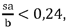


- Eine spitzenfreie Kraft-Weg-Kennlinie bzw. Kraft-Zeit-Kennlinie mit hohem Flächenintegral kann bei einem Hohlprofil mit beispielsweise zehn ebenen Seitenwandflächen unter folgenden Voraussetzungen erreicht werden, nämlich dass die ersten Seitenwände eine erste Breite bi aufweisen, dass die zweiten Seitenwände je zwei gerade Seitenabschnitte mit einer zweiten Breite hi aufweisen, wobei die zweiten Seitenabschnitte jeweils an eine Eckenabrundung anschließen und sich bis zur jeweiligen Längssicke erstrecken, wobei die Längssicken gerade verlaufende Sickenseitenwandabschnitte mit einer dritten Bereite si aufweisen, wobei das Hohlprofil folgende Bedingungen


- Das gleiche kann bei einem anderen Hohlprofil mit beispielsweise sechs ebenen Seitenwandflächen erreicht werden, wenn die Längssicken an die jeweiligen Eckenabrundungen anschließen und das Hohlprofil die folgende Bedingung

- Verlaufen die zweiten geraden Seitenabschnitte erfindungsgemässs normal zu den ersten geraden Seitenwänden, ist die Herstellung des Hohlprofils erleichterbar. Zudem kann diese geometrische Ausbildung dazu beitragen, dass sich im Schadensfall das Hohlprofil fein faltet und damit einen hohen Absorptionsgrad sicherstellt.
- Vorstehend Genanntes kann weiter verbessert werden, wenn die zweiten geraden Seitenabschnitte gleichlang und/oder die ersten geraden Seitenwände gleichlang sind.
- Für eine für Fahrzeugkarosserie geforderte Stauchkraft kann sich aus ausreichend herausstellen, wenn die Materialstärke d des Flachmaterials des Hohlprofils maximal 2 mm beträgt.
- Vorzugsweise liegt die Zugfestigkeit des Flachmaterials Rm im Bereich von 600 MPa bis 1200 MPa und ist die Bruchdehnung des Flachmaterials größer 9%, um so einen vergleichsweise hohen Absorptionsgrad am Energieabsorberelement sicherstellen zu können.
- Beispielsweise kann das Flachmaterial aus einem Dualphasenstahl oder Complexphasenstahl bestehen, um eine vergleichsweise hohe Stauchkraft am Energieabsorberelement zu erreichen.
- Besonders auszeichnen gegenüber dem Stand der Technik kann sich eine Fahrzeugkarosserie mit dem erfindungsgemäßen Energieabsorberelement.
- In den Figuren ist beispielsweise der Erfindungsgegenstand anhand mehrere Ausführungsvarianten näher dargestellt. Es zeigen
-
Fig. 1 eine Querschnittansicht zu einem Hohlprofil eines Energieabsorberelements nach dem Stand der Technik, -
Figuren 2 und3 Querschnittansichten zu Hohlprofilen von erfindungsgemäßen Energieabsorberelementen und -
Fig. 4 eine Darstellung zu Kraft-Zeit-Kennlinien der Energieabsorberelemente nach denFiguren 1 bis 3 . - Nach den
Figuren 1 bis 3 sind zu den Energieabsorberelement E1, E2, E3 dessen Hohlprofile 2 in einer Querschnittansicht dargestellt. Das geschlossene Hohlprofil 2 wird aus einem Flachmaterial mit einer Materialstärke d hergestellt. Beispielsweise wird zur Erzeugung der Energieabsorberelemente E2, E3 derFiguren 2 und3 ein Rollprofilierverfahren angewandt. - Das eine Profilhöhe h und eine Profilbreite b aufweisende Hohlprofil 2 wird von vier Seitenwänden 3, 4, 5, 6 gebildet, von denen zwei einander gegenüberliegende, erste Seitenwände 3, 4 gerade verlaufen. Die anderen beiden zweiten Seitenwände 5, 6 weisen jeweils eine offene Längssicke 7, 8 auf, die im Querschnitt dreieckförmig ausgebildet sind, und zwar geometrisch gleich ausgebildet, beispielsweise in Bezug auf Sickentiefe st, Sickenbreite sb, etc., und liegen sich direkt gegenüber. Die beiden Längssicken 7, 8 berühren sich nicht - es besteht zwischen deren Sickenböden 7.1, 8.1 ein Abstand sa.
- Das Hohlprofil 2 weist zudem an seinen vier Ecken je eine geometrisch gleiche Eckenabrundung 9.1, 9.2, 9.3, 9.4 mit dem gleichen Radius r auf. An diese Eckenabrundungen 9.1, 9.2, 9.3, 9.4 schließen die diesbezüglichen Seitenwände 3, 4, 5, 6 an - und zwar sowohl die jeweilige gerade verlaufende erste Seitenwand 3 bzw. 4 als auch die jeweilige zweite Seitenwand 5, 6. Um ein Energieabsorberelement E2, E3 mit hohem Absorptionsgrad und geringen Beschleunigungswerten auf Insassen des Kraftfahrzeugs sicherstellen zu können, muss das Hohlprofil 2 den folgenden Bedingungen genügen:
- Der Abstand sa zwischen den Sickenböden der Längssicke 7, 8 des Hohlprofils 2 dividiert durch die Profilbreite b des Hohlprofils 2 ist kleiner 0,24 bzw.

- Die Sickenbreite sb der Längssicke 7, 8 des Hohlprofils 2 dividiert durch die Differenz von Profilhöhe h des Hohlprofils 2 und zweimal den Radius r der Eckenrundung 9.1, 9.2, 9.3, 9.4 des Hohlprofils 2 ist größer 0,35 bzw.


- Profilbreite b des Hohlprofils 2 dividiert durch die Profilhöhe h des Hohlprofils 2 liegt im Bereich von 0,28 bis 0,74 bzw.

- In Tabelle 1 sind beispielsweise die geometrischen Abmessungen der verschiedenen Ausführungen zu den Hohlprofil 2 der Energieabsorberelement E1, E2 und E3 zu entnehmen.
Tabelle 1: Verschiedene Energieabsorberelemente b [mm] h [mm] bi [mm] hi [mm] sa [mm] sb [mm] si [mm] r [mm] d [mm] E1 66.92 108.44 33.92 6.22 28.25 63.00 11.55 16.50 1.5 E2 56.00 106.60 40.00 16.00 7.66 58.60 25.43 8.00 1.5 E3 55.38 115.90 22.38 0 2.97 82.90 26.42 16.50 1.5 b Profilbreite des Hohlprofils
h Profilhöhe des Hohlprofils
bi Bereite einer geraden ersten Seitenfläche des Hohlprofils
hi Bereite eines geraden zweiten Seitenabschnitts der zweiten Seitenfläche des Hohlprofils
sa Abstand zwischen den Sickenböden der Längssicken des Hohlprofils
sb Sickenbreite einer Längssicke
si Bereite des gerade verlaufenden Sickenwandabschnitts der Längssicke
r Radius der Eckenrundung des Hohlprofils
d Materialstärke des Flachmaterials des Hohlprofils - Gemäß den nach Tabelle 1 dargestellten geometrischen Abmessungen führt dies nach Tabelle 2 zu folgenden Verhältnissen an den Hohlprofilen.
Tabelle 2: Bedingungen zu den Hohlprofilen der Energieabsorberelemente nach Tabelle 1 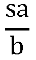


E1 0.422 0.84 0.62 0.54 0.18 2.94 - E2 0.137 0.65 0.53 0.63 0.40 1.57 - E3 0.054 1.00 0.48 - - - 11 - Wie der Tabelle 2 zu entnehmen, erfüllt das Hohlprofil 2 des Energieabsorberelements E1 die erfindungsgemäße erste Vorschrift (unterstrichen in Tabelle 2 dargestellt) der drei Vorschriften (von links nach rechts betrachtet) nach Anspruch 1 nicht. Außerdem werden zwei der weiteren Bedingungen nach Anspruch 2 vom E1 Hohlprofil 2 nicht erfüllt.
- Im Gegensatz dazu erfüllen die E2 und E3 Hohlprofile 2 der Energieabsorberelemente E2 und E3 die ersten drei Vorschriften und auch die weiteren Bedingungen, nämlich nach Anspruch 2 das E2 Hohlprofil 2 und nach Anspruch 3 das E3 Hohlprofil 2.
- Das Hohlprofil 2 des Energieabsorberelements E2 unterschiedet sich vom Hohlprofil 2 des Energieabsorberelements E3 durch die Anzahl an ebenen Seitenflächen. So weist das E2 Hohlprofil 2 zehn ebene Seitenflächen auf, wohingegen das E3 Hohlprofil 2 sechs ebene Seitenflächen aufweist.
- Dieser Unterschied kann daran erkannt werden, dass das E2 Hohlprofil 2 im Gegensatz zum E3 Hohlprofil an den zweiten Seitenwände 5, 6 je zwei gerade Seitenabschnitte 5.1, 5.2, 6.1, 6.2 mit einer zweiten Breite hi aufweist, wobei diese zweiten Seitenabschnitte 5.1, 5.2, 6.1, 6.2 jeweils an eine Eckenabrundung 9.1, 9.2, 9.3, 9.4 anschließen und sich bis zur jeweiligen Längssicke 7, 8 erstrecken.
Das E2 Hohlprofil 2 erfüllt zudem die an die ersten drei anschließenden weiteren drei Bedingungen der Tabelle 2, wobei in diese Bedingungen auch eine dritte Breite si eingeht - wobei diese dritte Bereite si der gerade verlaufenden Sickenseitenwandabschnitte 7.2, 7.3, 8.2, 8.3 der Längssicken 7, 8 zugehört. Hierzu wird im Allgemeinen erläutert, dass sich eine Zarge der Längssicken 7, 8 durch einen Sickenseitenwandabschnitt 7.2, 7.3, 8.2, 8.3 (auch bekannt unter gemeinsamen Tangentenstrecke) und den beiden daran anschließenden Radien der Längssicke 7, 8 ausbilden kann. - Das E3 Hohlprofil 2, das keine an die Eckenabrundungen 9.1, 9.2, 9.3, 9.4 anschließenden geraden Seitenabschnitte aufweist -hier schließen nämlich die Längssicken 7, 8 an die Eckenabrundungen 9.1, 9.2, 9.3, 9.4 an-, erfüllt die ganz rechte Bedingung der Tabelle 2 und stellt daher auch ein erfindungsgemäßes Ausführungsbeispiel dar.
- Damit können die erfindungsgemäßen E2, E3 Hohlprofile 2 -wie in
Fig. 4 dargestellteinen anfänglich steilen Kraftanstieg, in ein konstant hohes Kraftniveau überführen. Die E2, E3 Hohlprofile 2 können nämlich aufgrund einer feinen Faltung im Gegensatz zu dem E1 Hohlprofil 2 andere Kraftverläufe nahezu linear - und ohne Spitzen im Kraftverlauf - eine konstante Stauchkraft zur Absorption von Energie zur Verfügung stellen. Dies hält jene auf Insassen des Kraftfahrzeugs einwirkende Beschleunigung minimal, was die erfindungsgemäßen E2, E3 Hohlprofile 2 gegenüber anderen Hohlprofilen, welche die erfindungsgemäße Vorschrift nicht erfüllen, auszeichnet. - Wie zudem den Figuren zu entnehmen, verlaufen die zweiten geraden Seitenabschnitte 5.1, 5.2, 6.1, 6.2 normal zu den ersten geraden Seitenwänden 3, 4. Außerdem sind die zweiten geraden Seitenabschnitte 5.1, 5.2, 6.1, 6.2 gleich lang - dies trifft auch auf die ersten geraden Seitenwände 3, 4 zu. Die Materialstärke (d) des Flachmaterials des Hohlprofils 2 beträgt maximal 2 mm, nämlich 1,5 mm. Die Zugfestigkeit des Flachmaterials Rm liegt im Bereich von 600 MPa bis 1200 MPa, nämlich bei 800 MPa, und die Bruchdehnung des Flachmaterials ist größer 9% ist, nämlich ist 13%. Das Flachmaterial besteht aus einem Dualphasenstahl.
Claims (9)
- Energieabsorberelement für ein Kraftfahrzeug mit einem geschlossenen Hohlprofil (2) aus einem Flachmaterial mit einer Materialstärke (d), wobei das Hohlprofil (2) eine Profilhöhe (h), eine Profilbreite (b) und vier Seitenwände (3, 4, 5, 6) aufweist, von denen zwei einander gegenüberliegenden, erste Seitenwände (3, 4) gerade verlaufen und die anderen zwei einander gegenüberliegenden, zweiten Seitenwände (5, 6) je eine im Querschnitt dreieckförmige, insbesondere offene, Längssicke (7, 8) mit einer Sickenbreite (sb) aufweisen, welche Längssicken (7, 8) gleich ausgebildet sind und zwischen ihren einander gegenüberliegenden Sickenböden (7.1, 8.1) einen Abstand (sa) besteht, wobei das Hohlprofil (2) an den Ecken gleiche Eckenabrundungen (9.1, 9.2, 9.3, 9.4) mit einem Radius (r) aufweist, an die sowohl die jeweilige erste gerade Seitenwand (3, 4) als auch die jeweilige zweite Seitenwand (5, 6) anschließen, dadurch gekennzeichnet, dass das Hohlprofil (2) folgende Bedingungen


- Energieabsorberelement nach Anspruch 1, dadurch gekennzeichnet, dass die ersten Seitenwände (3, 4) eine erste Breite (bi) aufweisen, dass die zweiten Seitenwände (5, 6) je zwei gerade Seitenabschnitte (5.1, 5.2, 6.1, 6.2) mit einer zweiten Breite (hi) aufweisen, wobei die zweiten Seitenabschnitte (5.1, 5.2, 6.1, 6.2) jeweils an eine Eckenabrundung (9.1, 9.2, 9.3, 9.4) anschließen und sich bis zur jeweiligen Längssicke (7, 8) erstrecken, wobei die Längssicken (7, 8) gerade verlaufenden Sickenseitenwandabschnitte (7.2, 7.3, 8.2, 8.3) mit einer dritten Bereite (si) aufweisen, wobei das Hohlprofil (2) folgende Bedingungen


- Energieabsorberelement für ein Kraftfahrzeug mit einem geschlossenen Hohlprofil (2) aus einem Flachmaterial mit einer Materialstärke (d), wobei das Hohlprofil (2) eine Profilhöhe (h), eine Profilbreite (b) und vier Seitenwände (3, 4, 5, 6) aufweist, von denen zwei einander gegenüberliegenden, erste Seitenwände (3, 4) gerade verlaufen und die anderen zwei einander gegenüberliegenden, zweiten Seitenwände (5, 6) je eine im Querschnitt dreieckförmige, insbesondere offene, Längssicke (7, 8) mit einer Sickenbreite (sb) aufweisen, welche Längssicken (7, 8) gleich ausgebildet sind und zwischen ihren einander gegenüberliegenden Sickenböden (7.1, 8.1) einen Abstand (sa) besteht, wobei das Hohlprofil (2) an den Ecken gleiche Eckenabrundungen (9.1, 9.2, 9.3, 9.4) mit einem Radius (r) aufweist, an die sowohl die jeweilige erste gerade Seitenwand (3, 4) als auch die jeweilige zweite Seitenwand (5, 6) anschließen, dadurch gekennzeichnet, dass das Hohlprofil (2) folgende Bedingungen


- Energieabsorberelement nach einem der Ansprüche 1 bis 2, dadurch gekennzeichnet, dass die zweiten geraden Seitenabschnitte (5.1, 5.2, 6.1, 6.2) gleich lang sind.
- Energieabsorberelement nach einem der Ansprüche 1 bis 4, dadurch gekennzeichnet, dass die ersten geraden Seitenwände (3, 4) gleichlang sind.
- Energieabsorberelement nach einem der Ansprüche 1 bis 5, dadurch gekennzeichnet, dass die Materialstärke (d) maximal 2 mm beträgt.
- Energieabsorberelement nach einem der Ansprüche 1 bis 6, dadurch gekennzeichnet, dass die Zugfestigkeit des Flachmaterials Rm im Bereich von 600 MPa bis 1200 MPa liegt und die Bruchdehnung des Flachmaterials größer 9% ist.
- Energieabsorberelement nach einem der Ansprüche 1 bis 7, dadurch gekennzeichnet, dass das Flachmaterial aus einem Dualphasenstahl oder Complexphasenstahl besteht.
- Fahrzeugkarosserie mit einem Energieabsorberelement (E2, E3) nach einem der Ansprüche 1 bis 8.
Priority Applications (1)
| Application Number | Priority Date | Filing Date | Title |
|---|---|---|---|
| EP18165349.4A EP3546295B1 (de) | 2018-03-30 | 2018-03-30 | Energieabsorberelement für ein kraftfahrzeug |
Applications Claiming Priority (1)
| Application Number | Priority Date | Filing Date | Title |
|---|---|---|---|
| EP18165349.4A EP3546295B1 (de) | 2018-03-30 | 2018-03-30 | Energieabsorberelement für ein kraftfahrzeug |
Publications (2)
| Publication Number | Publication Date |
|---|---|
| EP3546295A1 EP3546295A1 (de) | 2019-10-02 |
| EP3546295B1 true EP3546295B1 (de) | 2021-02-24 |
Family
ID=61911384
Family Applications (1)
| Application Number | Title | Priority Date | Filing Date |
|---|---|---|---|
| EP18165349.4A Active EP3546295B1 (de) | 2018-03-30 | 2018-03-30 | Energieabsorberelement für ein kraftfahrzeug |
Country Status (1)
| Country | Link |
|---|---|
| EP (1) | EP3546295B1 (de) |
Family Cites Families (6)
| Publication number | Priority date | Publication date | Assignee | Title |
|---|---|---|---|---|
| JP2002154869A (ja) * | 2000-11-09 | 2002-05-28 | Narita Seitoushiyo:Kk | トルマリン鉱石含有焼結体およびその製造方法 |
| US7163241B2 (en) * | 2004-06-25 | 2007-01-16 | F.Tech R&D North America Inc. | Vehicle bumper beam having non-uniform cross sections |
| DE102005029738B4 (de) | 2005-06-24 | 2018-10-04 | GM Global Technology Operations LLC (n. d. Ges. d. Staates Delaware) | Energieabsorberelement und dieses verwendende Kraftfahrzeugkarosserie |
| JP5311762B2 (ja) * | 2007-05-30 | 2013-10-09 | 株式会社神戸製鋼所 | エネルギー吸収部材 |
| DE102013202607A1 (de) * | 2013-02-19 | 2014-08-21 | Magna International Inc. | Aufprallabsorptionselement |
| JP5926875B2 (ja) * | 2013-06-06 | 2016-05-25 | 豊田鉄工株式会社 | クラッシュボックス |
-
2018
- 2018-03-30 EP EP18165349.4A patent/EP3546295B1/de active Active
Non-Patent Citations (1)
| Title |
|---|
| None * |
Also Published As
| Publication number | Publication date |
|---|---|
| EP3546295A1 (de) | 2019-10-02 |
Similar Documents
| Publication | Publication Date | Title |
|---|---|---|
| DE102013114690B4 (de) | Außenpaneel für eine Fahrzeugsäule | |
| EP0718157B1 (de) | Stossstange für Fahrzeuge | |
| DE69931422T2 (de) | Aufprallträger für Kraftfahrzeuge | |
| EP1346861B1 (de) | Seitenaufprallträger | |
| DE102014110365A1 (de) | Rohrrückbalkenanordnung für ein Fahrzeug und Verfahren zur Herstellung derselben | |
| EP1481743A2 (de) | Blechelemente aus flexibel gewalztem Bandmaterial | |
| DE19525347C1 (de) | Leistenförmiges Strukturbauteil und Verfahren zu seiner Herstellung | |
| DE102011053354A1 (de) | Kombinierte Struktur einer äußeren oberen Mittelsäulenverstärkung und eines Sicherheitsgurthalters | |
| DE69403324T2 (de) | Verstärkende stossstange und fahrzeugseitenwand mit mindestens einer stossstange | |
| WO2016139070A1 (de) | Längsträger und querträger für einen fahrwerksrahmen eines schienenfahrzeuges | |
| DE2841796A1 (de) | Fahrzeugrahmen mit einem energieverzehrenden rahmenteil | |
| DE102011106152A1 (de) | Deformationselement einer Kraftfahrzeug-Karosserie | |
| DE102007005421A1 (de) | Stoßenergieverzehrelement für ein Fahrzeug | |
| DE69400849T2 (de) | Energieabsorptionsträger, insbesondere für Rahmenlängsträger oder Rahmenseitenträger für Fahrzeuge | |
| DE102004034519B3 (de) | Energie absorbierendes Trägerelement eines Kraftfahrzeugs | |
| DE2923292C2 (de) | ||
| EP3546295B1 (de) | Energieabsorberelement für ein kraftfahrzeug | |
| DE202013009443U1 (de) | Gummifederachse | |
| DE102012102215B4 (de) | Querträger für eine Stoßfängeranordnung eines Kraftfahrzeuges | |
| DE69508544T2 (de) | Energieabsorbierender Balken und dünnes metallisches Blech zu dessen Realisierung | |
| DE102014115938A1 (de) | Strukturträger für ein Kraftfahrzeug | |
| DE102014104222A1 (de) | Z-Walzprofil mit variierender Höhe und Verfahren zur Herstellung | |
| DE4303435C2 (de) | Rammschutzträger für Türen und Seitenwände von Kraftfahrzeugkarosserien | |
| EP2185463A1 (de) | Profilform für einen kranarm | |
| DE102021000251A1 (de) | Strukturelement für eine Fahrzeugkarosserie |
Legal Events
| Date | Code | Title | Description |
|---|---|---|---|
| PUAI | Public reference made under article 153(3) epc to a published international application that has entered the european phase |
Free format text: ORIGINAL CODE: 0009012 |
|
| STAA | Information on the status of an ep patent application or granted ep patent |
Free format text: STATUS: THE APPLICATION HAS BEEN PUBLISHED |
|
| AK | Designated contracting states |
Kind code of ref document: A1 Designated state(s): AL AT BE BG CH CY CZ DE DK EE ES FI FR GB GR HR HU IE IS IT LI LT LU LV MC MK MT NL NO PL PT RO RS SE SI SK SM TR |
|
| AX | Request for extension of the european patent |
Extension state: BA ME |
|
| STAA | Information on the status of an ep patent application or granted ep patent |
Free format text: STATUS: REQUEST FOR EXAMINATION WAS MADE |
|
| 17P | Request for examination filed |
Effective date: 20200602 |
|
| RBV | Designated contracting states (corrected) |
Designated state(s): AL AT BE BG CH CY CZ DE DK EE ES FI FR GB GR HR HU IE IS IT LI LT LU LV MC MK MT NL NO PL PT RO RS SE SI SK SM TR |
|
| RIC1 | Information provided on ipc code assigned before grant |
Ipc: B60R 19/18 20060101AFI20200715BHEP |
|
| GRAP | Despatch of communication of intention to grant a patent |
Free format text: ORIGINAL CODE: EPIDOSNIGR1 |
|
| STAA | Information on the status of an ep patent application or granted ep patent |
Free format text: STATUS: GRANT OF PATENT IS INTENDED |
|
| INTG | Intention to grant announced |
Effective date: 20200828 |
|
| GRAS | Grant fee paid |
Free format text: ORIGINAL CODE: EPIDOSNIGR3 |
|
| GRAA | (expected) grant |
Free format text: ORIGINAL CODE: 0009210 |
|
| STAA | Information on the status of an ep patent application or granted ep patent |
Free format text: STATUS: THE PATENT HAS BEEN GRANTED |
|
| AK | Designated contracting states |
Kind code of ref document: B1 Designated state(s): AL AT BE BG CH CY CZ DE DK EE ES FI FR GB GR HR HU IE IS IT LI LT LU LV MC MK MT NL NO PL PT RO RS SE SI SK SM TR |
|
| RAP1 | Party data changed (applicant data changed or rights of an application transferred) |
Owner name: VOESTALPINE KREMS GMBH |
|
| REG | Reference to a national code |
Ref country code: CH Ref legal event code: EP |
|
| REG | Reference to a national code |
Ref country code: AT Ref legal event code: REF Ref document number: 1364046 Country of ref document: AT Kind code of ref document: T Effective date: 20210315 |
|
| REG | Reference to a national code |
Ref country code: IE Ref legal event code: FG4D Free format text: LANGUAGE OF EP DOCUMENT: GERMAN |
|
| REG | Reference to a national code |
Ref country code: DE Ref legal event code: R096 Ref document number: 502018003956 Country of ref document: DE |
|
| REG | Reference to a national code |
Ref country code: LT Ref legal event code: MG9D |
|
| REG | Reference to a national code |
Ref country code: NL Ref legal event code: MP Effective date: 20210224 |
|
| PG25 | Lapsed in a contracting state [announced via postgrant information from national office to epo] |
Ref country code: LT Free format text: LAPSE BECAUSE OF FAILURE TO SUBMIT A TRANSLATION OF THE DESCRIPTION OR TO PAY THE FEE WITHIN THE PRESCRIBED TIME-LIMIT Effective date: 20210224 Ref country code: NO Free format text: LAPSE BECAUSE OF FAILURE TO SUBMIT A TRANSLATION OF THE DESCRIPTION OR TO PAY THE FEE WITHIN THE PRESCRIBED TIME-LIMIT Effective date: 20210524 Ref country code: PT Free format text: LAPSE BECAUSE OF FAILURE TO SUBMIT A TRANSLATION OF THE DESCRIPTION OR TO PAY THE FEE WITHIN THE PRESCRIBED TIME-LIMIT Effective date: 20210624 Ref country code: BG Free format text: LAPSE BECAUSE OF FAILURE TO SUBMIT A TRANSLATION OF THE DESCRIPTION OR TO PAY THE FEE WITHIN THE PRESCRIBED TIME-LIMIT Effective date: 20210524 Ref country code: FI Free format text: LAPSE BECAUSE OF FAILURE TO SUBMIT A TRANSLATION OF THE DESCRIPTION OR TO PAY THE FEE WITHIN THE PRESCRIBED TIME-LIMIT Effective date: 20210224 Ref country code: GR Free format text: LAPSE BECAUSE OF FAILURE TO SUBMIT A TRANSLATION OF THE DESCRIPTION OR TO PAY THE FEE WITHIN THE PRESCRIBED TIME-LIMIT Effective date: 20210525 Ref country code: HR Free format text: LAPSE BECAUSE OF FAILURE TO SUBMIT A TRANSLATION OF THE DESCRIPTION OR TO PAY THE FEE WITHIN THE PRESCRIBED TIME-LIMIT Effective date: 20210224 |
|
| PG25 | Lapsed in a contracting state [announced via postgrant information from national office to epo] |
Ref country code: NL Free format text: LAPSE BECAUSE OF FAILURE TO SUBMIT A TRANSLATION OF THE DESCRIPTION OR TO PAY THE FEE WITHIN THE PRESCRIBED TIME-LIMIT Effective date: 20210224 Ref country code: LV Free format text: LAPSE BECAUSE OF FAILURE TO SUBMIT A TRANSLATION OF THE DESCRIPTION OR TO PAY THE FEE WITHIN THE PRESCRIBED TIME-LIMIT Effective date: 20210224 Ref country code: RS Free format text: LAPSE BECAUSE OF FAILURE TO SUBMIT A TRANSLATION OF THE DESCRIPTION OR TO PAY THE FEE WITHIN THE PRESCRIBED TIME-LIMIT Effective date: 20210224 Ref country code: PL Free format text: LAPSE BECAUSE OF FAILURE TO SUBMIT A TRANSLATION OF THE DESCRIPTION OR TO PAY THE FEE WITHIN THE PRESCRIBED TIME-LIMIT Effective date: 20210224 Ref country code: SE Free format text: LAPSE BECAUSE OF FAILURE TO SUBMIT A TRANSLATION OF THE DESCRIPTION OR TO PAY THE FEE WITHIN THE PRESCRIBED TIME-LIMIT Effective date: 20210224 |
|
| PG25 | Lapsed in a contracting state [announced via postgrant information from national office to epo] |
Ref country code: IS Free format text: LAPSE BECAUSE OF FAILURE TO SUBMIT A TRANSLATION OF THE DESCRIPTION OR TO PAY THE FEE WITHIN THE PRESCRIBED TIME-LIMIT Effective date: 20210624 |
|
| PG25 | Lapsed in a contracting state [announced via postgrant information from national office to epo] |
Ref country code: SM Free format text: LAPSE BECAUSE OF FAILURE TO SUBMIT A TRANSLATION OF THE DESCRIPTION OR TO PAY THE FEE WITHIN THE PRESCRIBED TIME-LIMIT Effective date: 20210224 Ref country code: EE Free format text: LAPSE BECAUSE OF FAILURE TO SUBMIT A TRANSLATION OF THE DESCRIPTION OR TO PAY THE FEE WITHIN THE PRESCRIBED TIME-LIMIT Effective date: 20210224 Ref country code: CZ Free format text: LAPSE BECAUSE OF FAILURE TO SUBMIT A TRANSLATION OF THE DESCRIPTION OR TO PAY THE FEE WITHIN THE PRESCRIBED TIME-LIMIT Effective date: 20210224 |
|
| REG | Reference to a national code |
Ref country code: CH Ref legal event code: PL |
|
| REG | Reference to a national code |
Ref country code: DE Ref legal event code: R097 Ref document number: 502018003956 Country of ref document: DE |
|
| PG25 | Lapsed in a contracting state [announced via postgrant information from national office to epo] |
Ref country code: DK Free format text: LAPSE BECAUSE OF FAILURE TO SUBMIT A TRANSLATION OF THE DESCRIPTION OR TO PAY THE FEE WITHIN THE PRESCRIBED TIME-LIMIT Effective date: 20210224 Ref country code: SK Free format text: LAPSE BECAUSE OF FAILURE TO SUBMIT A TRANSLATION OF THE DESCRIPTION OR TO PAY THE FEE WITHIN THE PRESCRIBED TIME-LIMIT Effective date: 20210224 Ref country code: RO Free format text: LAPSE BECAUSE OF FAILURE TO SUBMIT A TRANSLATION OF THE DESCRIPTION OR TO PAY THE FEE WITHIN THE PRESCRIBED TIME-LIMIT Effective date: 20210224 Ref country code: MC Free format text: LAPSE BECAUSE OF FAILURE TO SUBMIT A TRANSLATION OF THE DESCRIPTION OR TO PAY THE FEE WITHIN THE PRESCRIBED TIME-LIMIT Effective date: 20210224 |
|
| REG | Reference to a national code |
Ref country code: BE Ref legal event code: MM Effective date: 20210331 |
|
| PLBE | No opposition filed within time limit |
Free format text: ORIGINAL CODE: 0009261 |
|
| STAA | Information on the status of an ep patent application or granted ep patent |
Free format text: STATUS: NO OPPOSITION FILED WITHIN TIME LIMIT |
|
| PG25 | Lapsed in a contracting state [announced via postgrant information from national office to epo] |
Ref country code: ES Free format text: LAPSE BECAUSE OF FAILURE TO SUBMIT A TRANSLATION OF THE DESCRIPTION OR TO PAY THE FEE WITHIN THE PRESCRIBED TIME-LIMIT Effective date: 20210224 Ref country code: LI Free format text: LAPSE BECAUSE OF NON-PAYMENT OF DUE FEES Effective date: 20210331 Ref country code: IE Free format text: LAPSE BECAUSE OF NON-PAYMENT OF DUE FEES Effective date: 20210330 Ref country code: LU Free format text: LAPSE BECAUSE OF NON-PAYMENT OF DUE FEES Effective date: 20210330 Ref country code: CH Free format text: LAPSE BECAUSE OF NON-PAYMENT OF DUE FEES Effective date: 20210331 Ref country code: AL Free format text: LAPSE BECAUSE OF FAILURE TO SUBMIT A TRANSLATION OF THE DESCRIPTION OR TO PAY THE FEE WITHIN THE PRESCRIBED TIME-LIMIT Effective date: 20210224 |
|
| 26N | No opposition filed |
Effective date: 20211125 |
|
| PG25 | Lapsed in a contracting state [announced via postgrant information from national office to epo] |
Ref country code: SI Free format text: LAPSE BECAUSE OF FAILURE TO SUBMIT A TRANSLATION OF THE DESCRIPTION OR TO PAY THE FEE WITHIN THE PRESCRIBED TIME-LIMIT Effective date: 20210224 |
|
| PG25 | Lapsed in a contracting state [announced via postgrant information from national office to epo] |
Ref country code: IS Free format text: LAPSE BECAUSE OF FAILURE TO SUBMIT A TRANSLATION OF THE DESCRIPTION OR TO PAY THE FEE WITHIN THE PRESCRIBED TIME-LIMIT Effective date: 20210624 |
|
| PG25 | Lapsed in a contracting state [announced via postgrant information from national office to epo] |
Ref country code: BE Free format text: LAPSE BECAUSE OF NON-PAYMENT OF DUE FEES Effective date: 20210331 |
|
| GBPC | Gb: european patent ceased through non-payment of renewal fee |
Effective date: 20220330 |
|
| PG25 | Lapsed in a contracting state [announced via postgrant information from national office to epo] |
Ref country code: GB Free format text: LAPSE BECAUSE OF NON-PAYMENT OF DUE FEES Effective date: 20220330 |
|
| PG25 | Lapsed in a contracting state [announced via postgrant information from national office to epo] |
Ref country code: CY Free format text: LAPSE BECAUSE OF FAILURE TO SUBMIT A TRANSLATION OF THE DESCRIPTION OR TO PAY THE FEE WITHIN THE PRESCRIBED TIME-LIMIT Effective date: 20210224 |
|
| PG25 | Lapsed in a contracting state [announced via postgrant information from national office to epo] |
Ref country code: HU Free format text: LAPSE BECAUSE OF FAILURE TO SUBMIT A TRANSLATION OF THE DESCRIPTION OR TO PAY THE FEE WITHIN THE PRESCRIBED TIME-LIMIT; INVALID AB INITIO Effective date: 20180330 |
|
| P01 | Opt-out of the competence of the unified patent court (upc) registered |
Effective date: 20230706 |
|
| PG25 | Lapsed in a contracting state [announced via postgrant information from national office to epo] |
Ref country code: MK Free format text: LAPSE BECAUSE OF FAILURE TO SUBMIT A TRANSLATION OF THE DESCRIPTION OR TO PAY THE FEE WITHIN THE PRESCRIBED TIME-LIMIT Effective date: 20210224 |
|
| PGFP | Annual fee paid to national office [announced via postgrant information from national office to epo] |
Ref country code: FR Payment date: 20240325 Year of fee payment: 7 |
|
| PG25 | Lapsed in a contracting state [announced via postgrant information from national office to epo] |
Ref country code: TR Free format text: LAPSE BECAUSE OF FAILURE TO SUBMIT A TRANSLATION OF THE DESCRIPTION OR TO PAY THE FEE WITHIN THE PRESCRIBED TIME-LIMIT Effective date: 20210224 |
|
| PG25 | Lapsed in a contracting state [announced via postgrant information from national office to epo] |
Ref country code: MT Free format text: LAPSE BECAUSE OF FAILURE TO SUBMIT A TRANSLATION OF THE DESCRIPTION OR TO PAY THE FEE WITHIN THE PRESCRIBED TIME-LIMIT Effective date: 20210224 |
|
| PG25 | Lapsed in a contracting state [announced via postgrant information from national office to epo] |
Ref country code: FR Free format text: LAPSE BECAUSE OF NON-PAYMENT OF DUE FEES Effective date: 20250331 |
|
| PGFP | Annual fee paid to national office [announced via postgrant information from national office to epo] |
Ref country code: DE Payment date: 20260327 Year of fee payment: 9 |
|
| PGFP | Annual fee paid to national office [announced via postgrant information from national office to epo] |
Ref country code: AT Payment date: 20260327 Year of fee payment: 9 |
|
| PGFP | Annual fee paid to national office [announced via postgrant information from national office to epo] |
Ref country code: IT Payment date: 20260319 Year of fee payment: 9 |