EP3546227B1 - Printer, control method of printer, and non-transitory computer-readable medium storing computer readable instructions - Google Patents
Printer, control method of printer, and non-transitory computer-readable medium storing computer readable instructions Download PDFInfo
- Publication number
- EP3546227B1 EP3546227B1 EP19163494.8A EP19163494A EP3546227B1 EP 3546227 B1 EP3546227 B1 EP 3546227B1 EP 19163494 A EP19163494 A EP 19163494A EP 3546227 B1 EP3546227 B1 EP 3546227B1
- Authority
- EP
- European Patent Office
- Prior art keywords
- tank
- flow path
- ink
- processing
- head
- Prior art date
- Legal status (The legal status is an assumption and is not a legal conclusion. Google has not performed a legal analysis and makes no representation as to the accuracy of the status listed.)
- Active
Links
- 238000000034 method Methods 0.000 title claims description 11
- 238000013019 agitation Methods 0.000 claims description 71
- 239000000976 ink Substances 0.000 description 244
- 238000004062 sedimentation Methods 0.000 description 13
- QVGXLLKOCUKJST-UHFFFAOYSA-N atomic oxygen Chemical compound [O] QVGXLLKOCUKJST-UHFFFAOYSA-N 0.000 description 3
- 239000007788 liquid Substances 0.000 description 3
- 229910052760 oxygen Inorganic materials 0.000 description 3
- 239000001301 oxygen Substances 0.000 description 3
- 239000003086 colorant Substances 0.000 description 2
- 230000007423 decrease Effects 0.000 description 2
- 238000010586 diagram Methods 0.000 description 2
- 238000006073 displacement reaction Methods 0.000 description 2
- 238000002360 preparation method Methods 0.000 description 2
- 239000004744 fabric Substances 0.000 description 1
- 238000011010 flushing procedure Methods 0.000 description 1
- 238000012986 modification Methods 0.000 description 1
- 230000004048 modification Effects 0.000 description 1
- 239000000049 pigment Substances 0.000 description 1
- 239000013049 sediment Substances 0.000 description 1
- 238000011144 upstream manufacturing Methods 0.000 description 1
Images


Classifications
-
- B—PERFORMING OPERATIONS; TRANSPORTING
- B41—PRINTING; LINING MACHINES; TYPEWRITERS; STAMPS
- B41J—TYPEWRITERS; SELECTIVE PRINTING MECHANISMS, i.e. MECHANISMS PRINTING OTHERWISE THAN FROM A FORME; CORRECTION OF TYPOGRAPHICAL ERRORS
- B41J2/00—Typewriters or selective printing mechanisms characterised by the printing or marking process for which they are designed
- B41J2/005—Typewriters or selective printing mechanisms characterised by the printing or marking process for which they are designed characterised by bringing liquid or particles selectively into contact with a printing material
- B41J2/01—Ink jet
- B41J2/17—Ink jet characterised by ink handling
- B41J2/175—Ink supply systems ; Circuit parts therefor
- B41J2/17503—Ink cartridges
- B41J2/17506—Refilling of the cartridge
- B41J2/17509—Whilst mounted in the printer
-
- B—PERFORMING OPERATIONS; TRANSPORTING
- B41—PRINTING; LINING MACHINES; TYPEWRITERS; STAMPS
- B41J—TYPEWRITERS; SELECTIVE PRINTING MECHANISMS, i.e. MECHANISMS PRINTING OTHERWISE THAN FROM A FORME; CORRECTION OF TYPOGRAPHICAL ERRORS
- B41J2/00—Typewriters or selective printing mechanisms characterised by the printing or marking process for which they are designed
- B41J2/005—Typewriters or selective printing mechanisms characterised by the printing or marking process for which they are designed characterised by bringing liquid or particles selectively into contact with a printing material
- B41J2/01—Ink jet
- B41J2/17—Ink jet characterised by ink handling
- B41J2/175—Ink supply systems ; Circuit parts therefor
- B41J2/17596—Ink pumps, ink valves
-
- B—PERFORMING OPERATIONS; TRANSPORTING
- B41—PRINTING; LINING MACHINES; TYPEWRITERS; STAMPS
- B41J—TYPEWRITERS; SELECTIVE PRINTING MECHANISMS, i.e. MECHANISMS PRINTING OTHERWISE THAN FROM A FORME; CORRECTION OF TYPOGRAPHICAL ERRORS
- B41J2/00—Typewriters or selective printing mechanisms characterised by the printing or marking process for which they are designed
- B41J2/005—Typewriters or selective printing mechanisms characterised by the printing or marking process for which they are designed characterised by bringing liquid or particles selectively into contact with a printing material
- B41J2/01—Ink jet
- B41J2/17—Ink jet characterised by ink handling
- B41J2/18—Ink recirculation systems
- B41J2/185—Ink-collectors; Ink-catchers
-
- B—PERFORMING OPERATIONS; TRANSPORTING
- B41—PRINTING; LINING MACHINES; TYPEWRITERS; STAMPS
- B41J—TYPEWRITERS; SELECTIVE PRINTING MECHANISMS, i.e. MECHANISMS PRINTING OTHERWISE THAN FROM A FORME; CORRECTION OF TYPOGRAPHICAL ERRORS
- B41J2/00—Typewriters or selective printing mechanisms characterised by the printing or marking process for which they are designed
- B41J2/005—Typewriters or selective printing mechanisms characterised by the printing or marking process for which they are designed characterised by bringing liquid or particles selectively into contact with a printing material
- B41J2/01—Ink jet
- B41J2/17—Ink jet characterised by ink handling
- B41J2/19—Ink jet characterised by ink handling for removing air bubbles
-
- B—PERFORMING OPERATIONS; TRANSPORTING
- B41—PRINTING; LINING MACHINES; TYPEWRITERS; STAMPS
- B41J—TYPEWRITERS; SELECTIVE PRINTING MECHANISMS, i.e. MECHANISMS PRINTING OTHERWISE THAN FROM A FORME; CORRECTION OF TYPOGRAPHICAL ERRORS
- B41J29/00—Details of, or accessories for, typewriters or selective printing mechanisms not otherwise provided for
- B41J29/38—Drives, motors, controls or automatic cut-off devices for the entire printing mechanism
Definitions
- the present invention relates to a printer, a control method of a printer, and a non-transitory computer-readable medium storing computer-readable instructions.
- a printer that circulates ink in order to remove air bubbles or eliminate sedimentation of ink components in a head or in a flow path from an ink tank to the head.
- a printer described in Japanese Laid-Open Patent Publication No. Hei 11-42795 is provided with an inter-tank supply path that supplies an ink in a main tank to a sub tank, and a deaerator provided in the inter-tank supply path.
- the ink in the main tank is deaerated by the deaerator and is supplied to the sub tank.
- the ink in the sub tank is supplied to a three-way valve via a flowmeter, a deaerator and a dissolved oxygen meter that are provided in an ink supply path.
- the ink supplied to the three-way valve is supplied to the head by an operation of the three-way valve when the ink is ejected.
- the ink is returned to the sub tank through an ink circulation path by an operation of the three-way valve.
- US 8,366,224 discloses an inkjet recording apparatus with a circulation path for circulating ink and a deaeration device.
- the inter-tank supply path is not provided with a bypass flow path that returns the ink to the main tank without feeding the ink to the sub tank. Therefore, at the time of printing in which the ink is supplied from the sub tank to the head, ink circulation cannot be performed in order to return the ink in the main tank to the main tank via the inter-tank supply path. Thus, the circulation of the ink in the main tank cannot be performed until the end of the printing.
- a printer according to a first aspect of the present invention is defined in appended claim 1.
- the printer when the printing is performed, it is possible to perform the printing-time circulation processing that circulates the ink in the main tank, the tank-side supply flow path, the first bypass flow path and the tank-side circulation flow path. Therefore, the printer can perform the printing-time circulation processing without waiting for the end of the printing, and it is thus possible to quickly replenish the sub tank with the ink that decreases during the printing.
- a deaeration portion configured to remove air from the ink may be provided in the tank-side supply flow path, and the processor may drive the deaeration portion and perform the printing-time circulation processing.
- the processor may drive the first pump and perform pre-filling circulation processing that circulates the ink in the main tank, the tank-side supply flow path, the first bypass flow path and the tank-side circulation flow path.
- the processor may drive the first pump and perform sub tank filling processing that supplies the ink from the main tank to the sub tank via the tank-side supply flow path.
- the pre-filling circulation processing is performed before the sub tank filling processing, it is possible to reduce air bubbles and precipitated ink components in the ink that is supplied from the main tank to the sub tank.
- the processor may perform first sub tank discharge processing that returns the ink from the sub tank to the main tank via the tank-side circulation flow path.
- the processor may perform unused state determination processing that determines whether a time period during which the ink is not ejected from the head exceeds a predetermined time period. When it is determined, in the unused state determination processing, that the time period during which the ink is not ejected from the head exceeds the predetermined time period, the processor may perform second sub tank discharge processing that returns the ink from the sub tank to the main tank via the tank-side circulation flow path.
- the ink in the sub tank is returned to the main tank by the second sub tank discharge processing.
- the ink in the sub tank is supplied from the main tank to the sub tank, it is possible to shorten the time period necessary to eliminate the sedimentation of the ink components in the sub tank.
- the printer may further include: a second pump provided in the tank-side circulation flow path; a head-side circulation flow path configured to return the ink from the head; a second bypass flow path configured to connect the head-side supply flow path and the head-side circulation flow path; and a third pump provided in the second bypass flow path.
- the processor may drive the second pump at a predetermined time interval and perform sub tank-side circulation processing that circulates the ink in the sub tank, the tank-side circulation flow path, the first bypass flow path and the tank-side supply flow path.
- the processor may drive the third pump and perform head-side circulation processing that circulates the ink in the head-side supply flow path, the head, the head-side circulation flow path and the second bypass flow path.
- the head-side circulation processing is performed at the time of the sub tank-side circulation processing, it is possible to shorten a time period required for the sub tank-side circulation processing and the head-side circulation processing that are performed at the predetermined time interval, in comparison to when the sub tank-side circulation processing and the head-side circulation processing are separately performed.
- the printer may further include: an agitation blade provided inside the main tank and configured to agitate the ink in the main tank; and a motor configured to drive the agitation blade.
- the processor may drive the motor and perform agitation processing of the ink in the main tank.
- the ink components precipitated in the main tank can be agitated by the agitation processing of the ink in the main tank. It is thus possible to reduce the precipitated components in the ink that is circulated by the printing-time circulation processing.
- the printer may further include: an agitation blade provided inside the main tank and configured to agitate the ink in the main tank; and a motor configured to drive the agitation blade.
- the processor may drive the motor and perform agitation processing of the ink in the main tank.
- the motor before the pre-filling circulation processing, the motor can be driven and the agitation of the ink in the main tank can be performed by the agitation processing. It is thus possible to reduce the precipitated ink components in the ink that is circulated by the pre-filling circulation processing.
- a control method of a printer is a control method of a printer.
- the printer includes: a head configured to eject an ink; a main tank configured to store the ink; a sub tank configured to store the ink supplied from the main tank; a tank-side supply flow path configured to supply the ink from the main tank to the sub tank; a tank-side circulation flow path configured to circulate the ink from the sub tank to the main tank; a first bypass flow path configured to connect the tank-side supply flow path and the tank-side circulation flow path; a head-side supply flow path configured to supply the ink from the sub tank to the head; a first pump provided in the tank-side supply flow path; and a processor.
- the control method of the printer is characterized by driving the first pump and performing printing-time circulation processing that circulates the ink in the main tank, the tank-side supply flow path, the first bypass flow path and the tank-side circulation flow path, when printing is performed by ejecting the ink from the head.
- a non-transitory computer-readable medium storing computer-readable instructions according to a third aspect of the present invention is characterized by causing a processor of a printer that includes: a head configured to eject an ink; a main tank configured to store the ink; a sub tank configured to store the ink supplied from the main tank; a tank-side supply flow path configured to supply the ink from the main tank to the sub tank; a tank-side circulation flow path configured to circulate the ink from the sub tank to the main tank; a first bypass flow path configured to connect the tank-side supply flow path and the tank-side circulation flow path; a head-side supply flow path configured to supply the ink from the sub tank to the head; a first pump provided in the tank-side supply flow path; and the processor, to drive the first pump and perform printing-time circulation processing that circulates the ink in the main tank, the tank-side supply flow path, the first bypass flow path and the tank-side circulation flow path, when printing is performed by ejecting the ink from the head.
- the upward direction, the downward direction, the left downward direction, the right upward direction, the right downward direction and the left upward direction in FIG. 1 respectively correspond to an upward direction, a downward direction, a front direction, a rear direction, a right direction and a left direction of the printer 1.
- the printer 1 is an inkjet printer that performs printing on a fabric such as a T-shirt, or a recording medium such as paper, by ejecting an ink 68 (refer to FIG. 2 ) from nozzles (not shown in the drawings) of a head portion 67 (refer to FIG. 2 ).
- the printer 1 prints a color image on the recording medium by downwardly ejecting, for example, five different types of the ink 68 (white (W), black (K), yellow (Y), cyan (C) and magenta (M)).
- white ink 68 is referred to as white ink.
- the white ink is an ink having higher settleability than the color inks.
- the printer 1 is provided with a housing 2, a platen drive mechanism 6, a pair of guide rails (not shown in the drawings), a platen 5, a tray 4, a frame body 10, a guide shaft 9, a rail 7, a carriage 20, head units 100 and 200, a drive belt 101 and a drive motor 19.
- An operation portion (not shown in the drawings) that is used to perform operations of the printer 1 is provided at a front position on the right side of the housing 2. The operation portion is operated when an operator inputs commands relating to various operations of the printer 1. Note that the operation on the operation portion may be an operation on a terminal, such as a personal computer (PC) connected to the printer 1.
- PC personal computer
- the frame body 10 has a substantially rectangular frame shape in a plan view, and is installed on an upper portion of the housing 2.
- the frame body 10 supports the guide shaft 9 and the rail 7, respectively, at the front side and the rear side of the frame body 10.
- the guide shaft 9 extends in the left-right direction on the inside of the frame body 10.
- the rail 7 is disposed facing the guide shaft 9 and extends in the left-right direction.
- the carriage 20 is supported such that it can be conveyed in the left-right direction along the guide shaft 9.
- the head units 100 and 200 are mounted on the carriage 20 such that they are aligned in the front-rear direction.
- the head unit 100 is positioned to the rear of the head unit 200.
- the head portion 67 (refer to FIG. 2 ) is provided on a lower portion of each of the head units 100 and 200.
- the head portion 67 of the head unit 100 ejects the white ink.
- the head portion 67 of the head unit 200 ejects the color inks.
- the head portion 67 is provided with a surface having the plurality of fine nozzles (not shown in the drawings) that can eject the ink 68 downward.
- the drive belt 101 is stretched along the left-right direction on the inside of the frame body 10.
- the drive motor 19 is coupled to the carriage 20 via the drive belt 101.
- the drive motor 19 drives the drive belt 101, the carriage 20 is caused to reciprocate in the left-right direction along the guide shaft 9.
- the platen drive mechanism 6 is provided with the pair of guide rails (not shown in the drawings) and a platen support base (not shown in the drawings).
- the pair of guide rails extend in the front-rear direction on the inside of the platen drive mechanism 6, and support the platen support base such that the platen support base can move in the front-rear direction.
- An upper portion of the platen support base supports the platen 5.
- the platen 5 supports the recording medium.
- the tray 4 is provided below the platen 5. When the operator places a T-shirt or the like on the platen 5, the tray 4 receives a sleeve or the like of the T-shirt, and thus protects the sleeve or the like such that the sleeve or the like does not come into contact with other components inside the housing 2.
- the platen drive mechanism 6 is driven by a sub-scanning drive portion (not shown in the drawings), and moves the platen support base and the platen 5 in the front-rear direction along the pair of guide rails.
- Printing by the printer 1 on the recording medium is performed by the platen 5 conveying the recording medium in the front-rear direction (a sub-scanning direction) and the ink 68 being ejected from the head portion 67 that is reciprocating in the left-right direction (a main scanning direction).
- the printer 1 is provided with the head portion 67, an ink supply portion 700 and a main tank 30.
- the ink supply portion 70 supplies the white ink 68 to the head portion 67.
- the head portion 67 is provided with inkjet type heads 671, 672, 673 and 674.
- An ink supply portion (not shown in the drawings) that supplies the other four colors of the ink 68 to the head portion 67 of the head unit 200 may have the same configuration as that shown in FIG. 2 .
- the main tank 30 supplies the white ink 68 to the ink supply portion 700, and stores the ink 68 returned from the ink supply portion 700.
- a shaft 40, a first tube 53, a second tube 54 and a remaining amount sensor 42 are inserted into the inside of the main tank 30.
- the main tank 30 is provided with a replenishment port 31 to replenish the ink 68, and the replenishment port 31 is provided with a lid 311.
- a lid sensor (not shown in the drawings) that detects the opening and closing of the lid 311 is provided in the vicinity of the replenishment port 31.
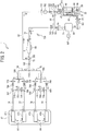
- the ink supply portion 700 supplies the ink 68 to the head portion 67. Further, the ink supply portion 700 is a portion through which the ink 68 circulates.
- the ink supply portion 700 is provided with tank-side supply flow paths 71 and 72, tank-side circulation flow paths 81 and 82, a first bypass flow path 85, head-side supply flow paths 76, 77, 78 and 79, connection flow paths 73, 74 and 75, second bypass flow paths 115 and 116, third bypass flow paths 83 and 84, a sub tank 8, a deaeration portion 60, pumps 751, 752, 753 and 754, a pressure reducing pump 601, electromagnetic valves 761, 762, 763, 764, 765, 766, 767, 768 and 769, and filters 771, 772, 773, 774, 775, 776, 777 and 778.
- the deaeration portion 60 reduces air bubbles in the ink 68 that flows through the tank-side supply flow path
- the sub tank 8 has a bag shape, for example, and stores the ink 68 supplied from the main tank 30. Further, as shown by two-dot chain lines in FIG. 2 , the ink 68 is supplied from the sub tank 8 to the heads 671 to 674 via the connection flow paths 73 to 75 and the head-side supply flow paths 76 to 79. The heads 671 to 674 eject the ink 68 supplied from the sub tank 8, and perform printing on a print target. A remaining amount sensor 89 that detects a remaining amount of the ink 68 is mounted on the sub tank 8. The remaining amount sensor 89 is formed by a full sensor and an empty sensor that are not shown in the drawings. An example of the full sensor will be explained.
- the sub tank 8 is a pouch
- an actuator that can operate in accordance with inflation of the pouch is disposed in the sub tank 8.
- the full sensor detects "FULL” for the ink 68 on the basis of displacement of the actuator.
- the empty sensor detects "Empty" for the ink 68 on the basis of the displacement of the actuator.
- the tank-side supply flow paths 71 and 72, the tank-side circulation flow paths 81 and 82, the first bypass flow path 85, the head-side supply flow paths 76, 77, 78 and 79, the connection flow paths 73, 74 and 75, and the second bypass flow paths 115 and 116 are formed by hollow tubes, for example.
- One end portion of the tank-side supply flow path 71 is connected to the first tube 53, and the other end portion of the tank-side supply flow path 71 is connected to one end portion of the tank-side supply flow path 72 at a connection portion 791.
- the other end portion of the tank-side supply flow path 72 is connected to the sub tank 8. Therefore, as shown by dotted lines in FIG. 2 , the ink 68 is supplied from the main tank 30 to the sub tank 8 via the tank-side supply flow path 71 and the tank-side supply flow path 72.
- One end portion of the tank-side circulation flow path 81 is connected to the second tube 54, and the other end potion of the tank-side circulation flow path 81 is connected to one end portion of the tank-side circulation flow path 82 at a connection portion 792.
- the other end portion of the tank-side circulation flow path 82 is connected to the sub tank 8. Therefore, the ink 68 is circulated from the sub tank 8 to the main tank 30 via the tank-side circulation flow path 81 and the tank-side circulation flow path 82.
- one end portion of the first bypass flow path 85 is connected to the tank-side supply flow paths 71 and 72 at the connection portion 791, and the other end portion of the first bypass flow path 85 is connected to the tank-side circulation flow paths 81 and 82 at the connection portion 792.
- a main tank-side circulation flow path is formed by the main tank 30, the tank-side supply flow path 71, the first bypass flow path 85 and the tank-side circulation flow path 81.
- a sub tank-side circulation flow path is formed by the tank-side supply flow path 72, the sub tank 8, the tank-side circulation flow path 82 and the first bypass flow path 85.
- connection flow path 73 is connected to the tank-side circulation flow path 82 at a connection portion 793, and the other end portion of the connection flow path 73 is connected to one end portion of the connection flow path 74 and to one end portion of the connection flow path 75 at a connection portion 794.
- the other end portion of the connection flow path 74 is connected to one end portion of the head-side supply flow path 76 and to one end portion of the head-side supply flow path 77 at a connection portion 795.
- the other end portion of the head-side supply flow path 76 is connected to the head 671 so as to supply the ink 68 to the head 671.
- the other end portion of the head-side supply flow path 77 is connected to the head 672 so as to supply the ink 68 to the head 672.
- the third bypass flow path 83 connects an ink flow path (not shown in the drawings) provided inside the head 671 and an ink flow path (not shown in the drawings) provided inside the head 672.
- connection flow path 75 is connected to one end portion of the head-side supply flow path 78 and to one end portion of the head-side supply flow path 79 at a connection portion 796.
- the other end portion of the head-side supply flow path 78 is connected to the head 673 so as to supply the ink 68 to the head 673.
- the other end portion of the head-side supply flow path 79 is connected to the head 674 so as to supply the ink 68 to the head 674.
- the third bypass flow path 84 connects an ink flow path (not shown in the drawings) provided inside the head 673 and an ink flow path (not shown in the drawings) provided inside the head 674.
- the head 671 and the head 672 may be a plurality of heads or may be a single head, and it is sufficient that the head 671 and the head 672 have an ink flow path through which the ink 68 supplied from one of the head-side supply flow path 76 and the head-side supply flow path 77 flows to the other. This also applies to the head 673 and the head 674.
- One end portion of the second bypass flow path 115 is connected to the head-side supply flow path 76 at a connection portion 797.
- the other end portion of the second bypass flow path 115 is connected to the head-side supply flow path 77 at a connection portion 798. Therefore, as shown by the solid lines in FIG. 2 , a first head-side circulation flow path is formed by the second bypass flow path 115, the head-side supply flow path 76, the head 671, the third bypass flow path 83, the head 672 and the head-side supply flow path 77.
- one end portion of the second bypass flow path 116 is connected to the head-side supply flow path 78 at a connection portion 799.
- the other end portion of the second bypass flow path 116 is connected to the head-side supply flow path 79 at a connection portion 800. Therefore, as shown by the solid lines in FIG. 2 , a second head-side circulation flow path is formed by the second bypass flow path 116, the head-side supply flow path 78, the head 673, the third bypass flow path 84, the head 674 and the head-side supply flow path 79.
- the electromagnetic valve 761 is provided in the tank-side supply flow path 71, between the deaeration portion 60 and the connection portion 791.
- the electromagnetic valve 761 is controlled by a CPU 70 (refer to FIG. 3 ) to be described later and opens and closes the tank-side supply flow path 71.
- the electromagnetic valve 762 is provided in the tank-side supply flow path 72, between the connection portion 791 and the sub tank 8.
- the electromagnetic valve 762 is controlled by the CPU 70 and opens and closes the tank-side supply flow path 72.
- the electromagnetic valve 763 is provided in the tank-side circulation flow path 82.
- the electromagnetic valve 763 is controlled by the CPU 70 and opens and closes the tank-side circulation flow path 82.
- the electromagnetic valve 764 is provided in the tank-side circulation flow path 81.
- the electromagnetic valve 764 is controlled by the CPU 70 and opens and closes the tank-side circulation flow path 81.
- the electromagnetic valve 765 is provided in the connection flow path 73, is controlled by the CPU 70, and opens and closes the connection flow path 73.
- the electromagnetic valves 766 to 769 are respectively provided in the head-side supply flow paths 76 to 79, are controlled by the CPU 70, and open and close the head-side supply flow paths 76 to 79.
- the filter 771 is provided in the tank-side supply flow path 71, between the main tank 30 and the pump 751 to be described later.
- the filter 772 is provided in the tank-side circulation flow path 82, between the sub tank 8 and the pump 752 to be described later.
- the filter 773 is provided in the head-side supply flow path 76, between the connection portion 795 and the electromagnetic valve 766.
- the filter 774 is provided in the head-side supply flow path 77, between the connection portion 795 and the electromagnetic valve 767.
- the filter 775 is provided in the second bypass flow path 115, between the connection portion 798 and the pump 753 to be described later.
- the filter 776 is provided in the head-side supply flow path 78, between the connection portion 796 and the electromagnetic valve 768.
- the filter 777 is provided in the head-side supply flow path 79, between the connection portion 796 and the electromagnetic valve 769.
- the filter 778 is provided in the second bypass flow path 116, between the connection portion 800 and the pump 754 to be described later. Note that the filters 771 to 778 remove foreign matter contained in the ink 68 that flows through the flow paths in which the filters 771 to 778 are respectively provided.
- the pump 751 is provided in the tank-side supply flow path 71, between the deaeration portion 60 and the filter 771.
- the pump 751 is controlled by the CPU 70, sucks up the ink 68 from the main tank 30, and causes the ink 68 to flow to the sub tank 8 side, which is a downstream side.
- the pump 752 is provided in the tank-side circulation flow path 82, between the filter 772 and the electromagnetic valve 763.
- the pump 752 is controlled by the CPU 70 and causes the ink 68 to flow from the sub tank 8 to the main tank 30.
- the pump 753 is provided in the second bypass flow path 115, between the filter 775 and the connection portion 797.
- the pump 753 is controlled by the CPU 70 and circulates the ink 68 in the first head-side circulation flow path.
- the pump 754 is provided in the second bypass flow path 116, between the filter 778 and the connection portion 799.
- the pump 754 is controlled by the CPU 70 and circulates the ink 68 in the second head-side circulation flow path.
- the pressure reducing pump 601 is connected to the deaeration portion 60.
- the pressure reducing pump 601 is controlled by the CPU 70 and depressurizes the deaeration portion 60. Therefore, air bubbles contained in the ink 68 that flows through the deaeration portion 60 are reduced.
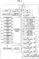
- the printer 1 is provided with the CPU 70 that controls the printer 1.
- the ROM 56 stores a control program, initial values and the like that are used by the CPU 70 to control operations of the printer 1.
- the RAM 57 temporarily stores various data that are used in the control program, and print data.
- the EEPROM 58 stores a date and time at which agitation processing (step S5), normal circulation processing (step S8) and main tank-side circulation processing (step S17), which will be described later, are performed, and stores a date and time at which the printer 1 is put into a stopped state.
- the head drive portion 61 is electrically connected to the head portion 67 that ejects the ink 68.
- the head drive portion 61 drives piezoelectric elements that are respectively provided in ejection channels of the heads 671 to 674 of the head portion 67, and causes the ink 68 to be ejected from the nozzles (not shown in the drawings).
- the main scanning drive portion 62 includes the drive motor 19 (refer to FIG. 1 ) and causes the carriage 20 to move in the main scanning direction.
- the sub-scanning drive portion 63 uses a drive motor (not shown in the drawings) to drive the platen drive mechanism 6 (refer to FIG. 1 ), and causes the platen 5 (refer to FIG. 1 ) to move in the sub-scanning direction.
- the CPU 70 controls the display control portion 51 and displays an image on a display 511.
- the operation processing portion 50 outputs, to the CPU 70, a signal that is based on an operation of an operation button 501 by a user.
- the remaining amount sensor 42 outputs, to the CPU 70, a signal indicating a remaining amount of the ink 68 in the main tank 30.
- the remaining amount sensor 89 outputs, to the CPU 70, a signal indicating a remaining amount (full or empty) of the ink 68 in the sub tank 8.
- the CPU 70 controls the opening and closing of the electromagnetic valves 761 to 769 via the electromagnetic valve drive portion 26, and opens and closes the tank-side supply flow paths 71 and 72, the tank-side circulation flow paths 81 and 82, the connection flow path 73, and the head-side supply flow paths 76 to 79.
- Each of the electromagnetic valves 761 to 769 can be individually controlled.
- the CPU 70 controls the pump drive portions 21 to 25 and drives the pumps 751 to 754 and the pressure reducing pump 601, respectively.
- the pumps 751 to 754 and the pressure reducing pump 601 can be respectively and individually controlled.
- the CPU 70 controls the wiper drive portion 64 and performs wiping of nozzle surfaces (not shown in the drawings) using wipers (not shown in the drawings).
- the CPU 70 controls the cap drive portion 65 and performs capping of the nozzle surfaces (not shown in the drawings) using caps (not shown in the drawings).
- the ink circulation processing is performed in order to remove air bubbles contained in the ink 68 in the ink flow paths and to eliminate sedimentation of ink components, such as pigments.
- the CPU 70 reads out, from the ROM 56, a program for main processing (not shown in the drawings) that performs main control of a printing operation etc. of the printer 1, a program for the ink circulation processing, and the like, and loads the programs to the RAM 57. In accordance with the programs, the CPU 70 performs the main processing and the ink circulation processing.
- the CPU 70 determines whether to perform initial ink introduction (step S1).
- the initial ink introduction is processing in which the user introduces the ink 68 into the main tank 30 and causes the sub tank 8 to be filled with the ink 68.
- the CPU 70 determines that the initial ink introduction is to be performed (yes at step S1).
- the CPU 70 determines whether or not the main tank 30 is filled with the ink 68 (step S2).
- the CPU 70 determines that the main tank 30 is filled with the ink 68 (yes at step S2). When the CPU 70 does not receive this signal from the remaining amount sensor 42 (no at step S2), the CPU 70 returns the processing to step S2.
- step S3 when the CPU 70 determines that the main tank 30 is filled with the ink 68 (yes at step S2), the CPU 70 performs initial introduction processing (step S3).
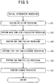
- the initial introduction processing will be explained with reference to FIG. 5 .
- the CPU 70 performs agitation processing (step S31) of the ink 68 in the main tank 30.
- the CPU 70 controls the agitation drive portion 27 and rotates an agitation motor 44 for a certain time period.
- the ink 68 in the main tank 30 is agitated by an agitation blade 46.
- An example of the certain time period is thirty minutes.
- the CPU 70 performs main tank-side circulation processing (step S32).
- the CPU 70 controls the electromagnetic valve drive portion 26, opens the electromagnetic valves 761 and 764, and closes the electromagnetic valves 762 and 763.
- the CPU 70 drives the pressure reducing pump 601 by controlling the pump drive portion 25, and depressurizes the deaeration portion 60.
- the CPU 70 controls the pump drive portion 21 and drives the pump 751.
- the circulation of the ink 68 is performed in the main tank-side circulation flow path for the certain time period.
- the CPU 70 drives the pump 751 by controlling the pump drive portion 21, and performs the main tank-side circulation processing of the ink 68 for a certain time period in the main tank-side circulation flow path.
- the air bubbles in the first bypass flow path 85 are returned from the tank-side circulation flow path 81 to the main tank 30, together with the ink 68.
- the air bubbles (air) contained in the ink 68 are deaerated by the deaeration portion 60.
- An example of the certain time period is five minutes.
- the CPU 70 stops the pump 751. Then, the CPU 70 performs sub tank filling processing (step S34).
- step S34 the CPU 70 closes the electromagnetic valve 765, opens the electromagnetic valves 761 and 762, and closes the electromagnetic valves 763 and 764.
- the CPU 70 drives the pressure reducing pump 601 by controlling the pump drive portion 25, and depressurizes the deaeration portion 60.
- the CPU 70 drives the pump 751 by controlling the pump drive portion 21, and fills the sub tank 8 with the ink 68 from the main tank 30, as shown by the dotted lines in FIG. 2 .
- the CPU 70 determines whether the sub tank 8 is full of the ink 68. For example, when a signal indicating that the sub tank 8 is full of the ink 68 is received from the remaining amount sensor 89, the CPU 70 determines that the sub tank 8 is full.
- the CPU 70 stops the pump 751 and the pressure reducing pump 601.
- the CPU 70 performs first sub tank discharge processing (step S35).
- the CPU 70 closes the electromagnetic valves 761 and 762 and opens the electromagnetic valves 763 and 764.
- the CPU 70 drives the pump 752 by controlling the pump drive portion 22, and returns the ink 68 from the sub tank 8 to the main tank 30.
- the CPU 70 determines whether the sub tank 8 is empty of the ink 68. For example, when a signal indicating that the sub tank 8 is empty of the ink 68 is received from the remaining amount sensor 89, the CPU 70 determines that the sub tank 8 is empty. Next, the CPU 70 controls the pump drive portion 22 and stops the pump 752.
- step S36 the CPU 70 performs sub tank filling processing.
- step S35 the first sub tank discharge processing
- step S35 the sub tank 8 is in a deflated state. Therefore, it is necessary to replenish the sub tank 8 with the ink 68 in order to prepare for the printing.
- step S37 the CPU 70 performs standby processing. In the standby processing, the CPU 70 opens the electromagnetic valves 765 to 769 and closes the electromagnetic valves 761 to 764.
- step S3 the initial introduction processing
- step S4 determines whether it is a time to perform main tank agitation. For example, in the determination processing at step S4, the CPU 70 determines whether a certain time period has elapsed from the time of the previous agitation processing (step S5) stored in the EEPROM 58. An example of the certain time period is one hour.
- the agitation processing (step S5) is processing in which the ink 68 in the main tank 30 is agitated by the agitation blade 46.
- the CPU 70 stores the time in the EEPROM 58.
- step S5 When the CPU 70 determines that it is the time to perform the main tank agitation (yes at step S4), the CPU 70 performs the agitation processing (step S5).
- the agitation processing (step S5) is the same as the agitation processing (step S31) shown in FIG. 5 , except an agitation time period.
- An example of the agitation time period at step S5 is five minutes.
- the CPU 70 returns the processing to step S1.
- the CPU 70 determines whether it is a time to perform ink circulation (step S6). For example, in the determination processing at step S6, the CPU 70 determines whether a certain time period has elapsed from the time of the previous normal circulation processing (step S8) stored in the EEPROM 58. An example of the certain time period is six hours.
- the CPU 70 determines that it is the time to perform the ink circulation (yes at step S6), the CPU 70 performs the normal circulation processing (step S8).
- the normal circulation processing will be explained with reference to FIG. 6 . First, the CPU 70 performs agitation processing (step S81).
- the agitation processing (step S81) is the same as the agitation processing (step S5), and an explanation thereof is thus omitted here.
- the CPU 70 starts sub tank-side circulation processing (step S83).
- the CPU 70 starts head-side circulation processing (step S84).
- the sub tank-side circulation processing may be continued or ended.
- the CPU 70 closes the electromagnetic valves 765, 761 and 764 and opens the electromagnetic valves 762 and 763, thus forming the sub tank-side circulation flow path.
- the CPU 70 drives the pump 752 and performs the circulation of the ink 68 for a certain time period in the sub tank-side circulation flow path. An example of the certain time period is three minutes.
- the CPU 70 stops the pump 752.
- the CPU 70 closes the electromagnetic valves 766, 767, 768 and 769 and forms the first head-side circulation flow path and the second head-side circulation flow path.
- the electromagnetic valve 765 may be in a closed state or in an open state.
- the CPU 70 drives the pump 753 and performs head-side circulation, in which the ink 68 is circulated in the first head-side circulation flow path, for a certain time period, as shown by the solid lines in FIG. 2 .
- the CPU 70 drives the pump 754 and performs head-side circulation, in which the ink 68 is circulated in the second head-side circulation flow path, for a certain time period, as shown by the solid lines in FIG. 2 .
- an example of each of the certain time periods is three minutes.
- the CPU 70 stores the time in the EEPROM 58 and returns the processing to step S1.
- the CPU 70 determines whether to end the printing operation (step S9).
- the printer 1 after the end of the printing operation, when a time period during which the ink 68 is not ejected from the nozzles (not shown in the drawings) of the heads 671 to 674 exceeds a predetermined time period, there is a possibility that sedimentation of components of the ink 68 in the sub tank 8 may occur.
- the circulation can be considered, for example. However, the circulation requires a certain time period.
- the printer 1 can also reduce the sediment of the ink 68 in the sub tank 8.
- the CPU 70 determines that the printing operation is to be ended (yes at step S9), and performs second sub tank discharge processing (step S10).
- the processing at step S10 is the same as the first sub tank discharge processing (step S35), and an explanation thereof is thus omitted here.
- the CPU 70 performs the capping of the nozzle surfaces (not shown in the drawings) of the heads 671 to 674 by causing the cap drive portion 65 to drive the caps (not shown in the drawings), and puts the printer 1 into the stopped state.
- the CPU 70 stores the time at which the printer 1 is put into the stopped state in the EEPROM 58.
- the CPU 70 determines whether the printer 1 has been left unused for a certain time period (step S11). Note that, in the present example in an unused state for the certain time period, the printer 1 is in the stopped state.
- the stopped state is, for example, a state in which the power source of the printer 1 is OFF.
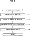
- the CPU 70 determines that the certain tine period has elapsed from the time at which the printer 1 is put into the stopped state stored in the EEPROM 58, the CPU 70 determines that the printer 1 has been left unused (yes at step S11) and performs post-unused-period processing (step S12). The post-unused-period processing will be explained with reference to FIG.
- the CPU 70 performs agitation processing (step S121).
- agitation processing As the preparation for the printing, it is necessary for the ink 68 in the main tank 30 that is located on the most upstream side of the ink supply portion 700 to be in a uniform state as a result of the sedimentation being resolved before the ink 68 is supplied to the downstream side of the ink supply portion 700.
- the agitation processing is a processing operation that is performed before the printing operation is started after the printer 1 has been left unused.
- the agitation processing (step S121) is the same as the processing at step S31, and an explanation thereof is thus omitted here.
- the CPU 70 performs sub tank filling processing (step S122).
- the sub tank filling processing (step S122) is the same as the sub tank filling processing (step S34), and an explanation thereof is thus omitted here.
- the CPU 70 performs sub tank-side circulation processing (step S123).
- the sub tank-side circulation processing (step S123) is the same as the sub tank-side circulation processing (step S83) except the time period, and an explanation thereof is thus omitted here.
- the circulation time period of the sub tank-side circulation processing (step S123) is longer than that of the processing at step S83, and is ten minutes, for example.
- the CPU 70 performs standby processing (step S124).
- step S124 is the same as the standby processing (step S37) shown in FIG. 5 , and an explanation thereof is thus omitted here. Note that, when the standby processing (step S37) is performed, the CPU 70 may perform flushing processing, wiping processing and the like of the heads 671 to 674. Next, the CPU 70 returns the processing to step S1.
- the CPU 70 determines whether the printing is being performed (step S13). For example, when the printing operation is started, the CPU 70 stores "ON" of a printing flag in the RAM 57, and when the printing operation is ended, the CPU 70 stores "OFF" of the printing flag in the RAM 57. Therefore, when the printing flag is ON, the CPU 70 determines that the printing is being performed (yes at step S13). When the CPU 70 determines that the printing is being performed (yes at step S13), the CPU 70 determines whether to perform ink circulation (step S15).
- the CPU 70 determines that the ink circulation is to be performed (yes at step S15) when one of the following cases occurs: a case in which the operation button 501 is operated and a command to perform the main tank-side circulation processing is received from the operation processing portion 50; a case in which the command to perform the main tank-side circulation processing is received from a PC connected to the printer 1; a case in which the main tank-side circulation processing is commanded by the program; a case in which a signal indicating that the main tank 30 has been replenished with the ink 68 is received; and a case in which a signal indicating that the sub tank 8 is to be filled with the ink 68.
- the case in which the signal indicating that the main tank 30 has been replenished with the ink 68 is, for example, a case in which the remaining amount sensor 42 detects that the amount of the ink 68 in the main tank 30 is larger than a certain amount, or a case in which a signal indicating that the lid 311 of the main tank 30 is closed is received from the lid sensor (not shown in the drawings).
- the case in which the signal indicating that the sub tank 8 is to be filled with the ink 68 is, for example, a case in which a signal indicating that the remaining amount of the ink 68 is equal to or less than a certain amount (hereinafter also referred to as "sub tank empty") is received from the remaining amount sensor 89 of the sub tank 8.
- the main tank 30 When the amount of the ink 68 in the main tank 30 is greater than the certain amount, and when the lid 311 of the main tank 30 is closed, the main tank 30 is replenished with the ink 68, and it is necessary to perform the agitation processing and the circulation processing of the ink 68. Further, in the case of "sub tank empty", it is desirable to perform the agitation processing and the circulation processing of the ink 68 on the main tank 30 side, in preparation for the filling of the sub tank 8 with the ink 68.
- the CPU 70 determines "YES" in the determination at step S15, the CPU 70 performs agitation processing (step S16).
- the agitation processing (step S16) is the same as the agitation processing (step S31), and an explanation thereof is thus omitted here.
- the CPU 70 performs main tank-side circulation processing (step S17).
- the main tank-side circulation processing (step S17) is the same as the main tank-side circulation processing (step S32), and an explanation thereof is thus omitted here. Note that, even when the printing is being performed and the printing flag ON is stored in the RAM 57, the CPU 70 performs the main tank-side circulation processing (step S17) in parallel with the printing operation. An example of the time period of the main tank-side circulation processing is three minutes.
- the CPU 70 stores, in the EEPROM 58, the time at which the main tank-side circulation process is ended.
- the CPU 70 determines whether the "sub tank empty” state has occurred (step S18). For example, when the signal indicating "sub tank empty” is received from the remaining amount sensor 89 of the sub tank 8, the CPU 70 determines that the "sub tank empty” state has occurred (yes at step S18). Next, when the printing flag becomes OFF, the CPU 70 performs sub tank filling processing (step S19). The sub tank filling processing (step S19) is the same as the sub tank filling processing (step S34), and an explanation thereof is thus omitted here. Next, the CPU 70 returns the processing to step S1. Further, also when the CPU 70 determines "NO" in the determination processing at step S18, the CPU 70 returns the processing to step S1.
- step S20 determines whether the "sub tank empty” state has occurred.
- the determination processing at step S20 is the same as the determination processing at step S18, and an explanation thereof is thus omitted here.
- the CPU 70 determines "YES” in the determination processing at step S20, the CPU 70 performs sub tank filling processing (step S21).
- the sub tank filling processing (step S21) is the same as the sub tank filling processing (step S34), and an explanation thereof is thus omitted here.
- the CPU 70 returns the processing to step S1 after the processing at step S21.
- the CPU 70 determines whether to agitate the ink 68 in the main tank 30 (step S22). For example, the CPU 70 determines that the agitation is to be performed (yes at step S22) when one of the following cases occurs: a case in which the operation button 501 is operated and a command to perform the agitation processing is received from the operation processing portion 50; a case in which the command to perform the agitation processing is received from a PC connected to the printer 1; and a case in which the agitation processing is commanded by the program.
- the CPU 70 determines "YES" in the determination processing at step S22, the CPU 70 performs agitation processing (step S23).
- the agitation processing (step S23) is the same as the agitation processing (step S5), and an explanation thereof is thus omitted here.
- the CPU 70 returns the processing to step S1.
- the printer 1 when the printing is performed by ejecting the ink 68 from the heads 671 to 674, the CPU 70 performs the main tank-side circulation processing (step S17) that circulates the ink 68 in the tank-side circulation flow path, in parallel with the printing operation. Therefore, the printer 1 can perform the main tank-side circulation processing (step S17) without waiting for the end of the printing. It is thus possible to quickly replenish the sub tank 8 with the ink 68 that decreases during the printing.
- the deaeration portion 60 which removes air from the ink 68, is provided in the tank-side supply flow path 71.
- the CPU 70 drives the deaeration portion 60 and performs the main tank-side circulation processing (step S17).
- the printer 1 can perform the processing that removes air from the circulating ink 68. It is thus possible to accumulate the deaerated ink 68 in advance in the main tank 30 before the ink 68 is supplied from the main tank 30 to the sub tank 8. Further, when the ink 68 is supplied to the sub tank 8, the ink 68 that has already been deaerated can be supplied, and it is possible to shorten a time period required for the ink supply to the sub tank 8.
- the CPU 70 performs the main tank-side circulation processing (step S32) that circulates the ink 68, and after the main tank-side circulation processing, the CPU 70 performs the sub tank filling processing (step S36). In this manner, since the main tank-side circulation processing is performed before the sub tank filling processing, it is possible to reduce the air bubbles and the precipitated ink components in the ink 68 that is supplied from the main tank 30 to the sub tank 8.
- the CPU 70 before the sub tank filling processing (step S36), the CPU 70 performs the first sub tank discharge processing (step S35). Therefore, by performing the first sub tank discharge processing, it is possible to reduce the ink 68 that may contain the air bubbles and the precipitated ink components inside the sub tank 8. It is thus is possible to further reduce the air bubbles and the precipitated ink components in the ink 68 in the sub tank 8 after the sub tank filling processing (step S36).
- step S9 when it is determined that the printing operation is to be ended (yes at step S9), the CPU 70 performs the second sub tank discharge processing (step S10) that returns the ink 68 from the sub tank 8 to the main tank 30.
- the ink 68 is not ejected for the predetermined time period, the possibility of the occurrence of sedimentation of the ink components in the sub tank 8 becomes higher. Further, in order to eliminate the sedimentation of the ink components in the sub tank 8, it takes time to perform the sub tank-side circulation processing.
- the ink 68 in the sub tank 8 is returned to the main tank 30 by the second sub tank discharge processing.
- the CPU 70 performs the sub tank-side circulation processing (step S83) and the head-side circulation processing (step S84) at a predetermined time interval. Therefore, the time period required for the sub tank-side circulation processing and the head-side circulation processing can be shortened, in comparison to when the sub tank-side circulation processing and the head-side circulation processing are performed separately.
- the CPU 70 performs the agitation processing (step S16) before the main tank-side circulation processing (step S17). Therefore, since the agitation processing of the ink 68 in the main tank 30 is performed before the main tank-side circulation processing, it is possible to agitate the ink components precipitated in the main tank 30. Thus, by performing the main tank-side circulation processing, it is possible to reduce the precipitated components in the ink 68 that is circulated.
- the CPU 70 performs the agitation processing (step S31) before the main tank-side circulation processing (step S32). It is therefore possible to reduce the precipitated ink components in the ink 68 that is circulated by the main tank-side circulation processing. Further, since the agitation processing is performed before the main tank-side circulation processing, even when the ink 68 in the main tank 30 ripples due to the agitation processing, the main tank-side circulation processing is not performed simultaneously, and it is possible to reduce the possibility of the circulation of the ink 68 containing air bubbles.
- the CPU 70 is an example of a "control portion" of the present invention.
- the heads 671 to 674 are an example of a "head” of the present invention.
- the pump 751 is an example of a "first pump” of the present invention.
- the pump 752 is an example of a “second pump” of the present invention.
- the pumps 753 and 754 are an example of a "third pump” of the present invention.
- the processing at step S16 is an example of "agitation processing” that is performed before printing-time circulation processing of the present invention.
- the processing at step S17 is an example of the "printing-time circulation processing" and a "printing-time circulation processing step” of the present invention.
- the processing at step S31 is an example of "agitation processing” that is performed before pre-filling circulation processing of the present invention.
- the processing at step S32 is an example of the "pre-filling circulation processing” of the present invention.
- the processing at step S36 is an example of "sub tank filling processing" of the present invention.
- the processing at step S35 is an example of "first sub tank discharge processing” of the present invention.
- the determination processing at step S9 is an example of "unused state determination processing” of the present invention.
- the processing at step S10 is an example of "second sub tank discharge processing” of the present invention.
- the processing at step S83 is an example of "sub tank-side circulation processing” of the present invention.
- the processing at step S84 is an example of "head-side circulation processing" of the present invention.
- the CPU 70 need not necessarily simultaneously perform the sub tank-side circulation processing (step S83) and the head-side circulation processing (step S84).
- the CPU 70 may start the sub tank-side circulation processing (step S83) before the head-side circulation processing (step S84), and may simultaneously end the sub tank-side circulation processing and the head-side circulation processing. Further, the CPU 70 may simultaneously perform the agitation processing (step S81), the sub-tank-side circulation processing (step S83) and the head-side circulation processing (step S84).
- the CPU 70 may start the operation in order of the agitation processing (step S81), the sub tank-side circulation processing (step S83) and the head-side circulation processing (step S84), may perform these processing operations in parallel with each other, and may simultaneously end them.
- the circulation time period of the head-side circulation processing (step S84) is not limited to three minutes, and may be appropriately set depending on sedimentation characteristics of the components of the ink 68 and a liquid feeding ability of the pumps 753 and 754.
- the agitation time period of the agitation processing is not limited to thirty minutes, and may be appropriately set depending on the amount of the ink 68 to be introduced into the main tank 30 and an agitation ability of the agitation blade 46.
- the CPU 70 need not necessarily depressurize the deaeration portion 60 to create a state in which the deaeration is possible.
- the circulation time period of the main tank-side circulation processing is not limited to five minutes, and may be appropriately set depending on the remaining amount of the ink 68 in the main tank 30 and the liquid feeding ability of the pump 751.
- the time interval of the agitation processing is not limited to one hour.
- the agitation time period of the agitation processing (step S5) is not limited to five minutes.
- the time interval and the agitation time period may be appropriately set depending on the sedimentation characteristics of the components of the ink 68.
- the time interval of the normal circulation processing (step S8) is not limited to six hours.
- the circulation time period of the sub tank-side circulation processing (step S83) is not limited to three minutes.
- the CPU 70 may determine that the printing operation is to be ended (yes at step S9).
- the circulation time period of the sub tank-side circulation processing (step S123) of the post-unused-period processing (step S12) is not limited to ten minutes. The circulation time period may be appropriately set depending on the remaining amount of the ink 68 in the sub tank 8 and the liquid feeding ability of the pump 752, respectively.
- an electromagnetic valve may be provided in the first bypass flow path 85 and the pump 752 may be provided in the tank-side circulation flow path 81.
- the CPU 70 closes the electromagnetic valve of the first bypass flow path 85 and the electromagnetic valves 761 and 762, and opens the electromagnetic valves 763 and 764. Then, the CPU 70 may drive the pump 752 of the tank-side circulation flow path 81 and may return the ink 68 from the sub tank 8 to the main tank 30.
- the number of the heads of the head portion 67 is not limited to four. Further, the sub tank 8 need not necessarily be provided.
- the agitation processing (step S16) need not necessarily be performed before the main tank-side circulation processing (step S17). Further, the agitation processing (step S31) need not necessarily be performed before the main tank-side circulation processing (step S32).
- the deaeration portion 60 need not necessarily be provided. Further, the deaeration processing need not necessarily be performed in the main tank-side circulation processing (step S17, step S32). Further, the agitation processing (step S81) need not necessarily be performed before the sub tank-side circulation processing (step S83). The agitation processing (step S121) need not necessarily be performed before the sub tank-side circulation processing (step S122).
Description
- The present invention relates to a printer, a control method of a printer, and a non-transitory computer-readable medium storing computer-readable instructions.
- A printer is known that circulates ink in order to remove air bubbles or eliminate sedimentation of ink components in a head or in a flow path from an ink tank to the head. For example, a printer described in Japanese Laid-Open Patent Publication No. Hei
11-42795 -
US 8,366,224 discloses an inkjet recording apparatus with a circulation path for circulating ink and a deaeration device. - However, in the printer described in the above-described publication, the inter-tank supply path is not provided with a bypass flow path that returns the ink to the main tank without feeding the ink to the sub tank. Therefore, at the time of printing in which the ink is supplied from the sub tank to the head, ink circulation cannot be performed in order to return the ink in the main tank to the main tank via the inter-tank supply path. Thus, the circulation of the ink in the main tank cannot be performed until the end of the printing.
- It is an object of the present invention to provide a printer, a control method of a printer, and a non-transitory computer-readable medium storing computer readable instructions that make it possible to circulate ink in a main tank even at a time of printing.
- A printer according to a first aspect of the present invention is defined in appended
claim 1. - In this case, when the printing is performed, it is possible to perform the printing-time circulation processing that circulates the ink in the main tank, the tank-side supply flow path, the first bypass flow path and the tank-side circulation flow path. Therefore, the printer can perform the printing-time circulation processing without waiting for the end of the printing, and it is thus possible to quickly replenish the sub tank with the ink that decreases during the printing.
- Further, a deaeration portion configured to remove air from the ink may be provided in the tank-side supply flow path, and the processor may drive the deaeration portion and perform the printing-time circulation processing.
- In this case, in the printing-time circulation processing, it is possible to perform processing that removes air from the circulating ink. It is thus possible to accumulate the deaerated ink in advance in the main tank before the ink is supplied from the main tank to the sub tank.
- Further, before the printing-time circulation processing, the processor may drive the first pump and perform pre-filling circulation processing that circulates the ink in the main tank, the tank-side supply flow path, the first bypass flow path and the tank-side circulation flow path. After the pre-filling circulation processing, the processor may drive the first pump and perform sub tank filling processing that supplies the ink from the main tank to the sub tank via the tank-side supply flow path.
- In this case, since the pre-filling circulation processing is performed before the sub tank filling processing, it is possible to reduce air bubbles and precipitated ink components in the ink that is supplied from the main tank to the sub tank.
- Before the sub tank filling processing, the processor may perform first sub tank discharge processing that returns the ink from the sub tank to the main tank via the tank-side circulation flow path.
- In this case, by performing the first sub tank discharge processing, it is possible to reduce the ink that may contain the air bubbles and the precipitated ink components inside the sub tank. It is thus is possible to further reduce the air bubbles and the precipitated ink components in the ink in the sub tank after the sub tank filling processing.
- The processor may perform unused state determination processing that determines whether a time period during which the ink is not ejected from the head exceeds a predetermined time period. When it is determined, in the unused state determination processing, that the time period during which the ink is not ejected from the head exceeds the predetermined time period, the processor may perform second sub tank discharge processing that returns the ink from the sub tank to the main tank via the tank-side circulation flow path.
- When the ink is not ejected for the predetermined time period, the possibility of the occurrence of sedimentation of the ink components becomes higher. Further, it takes time to eliminate the sedimentation of the ink components in the sub tank. On the other hand, when it is determined, in the unused state determination processing, that the time period during which the ink is not ejected from the head exceeds the predetermined time period, the ink in the sub tank is returned to the main tank by the second sub tank discharge processing. Thus, when the ink is supplied from the main tank to the sub tank, it is possible to shorten the time period necessary to eliminate the sedimentation of the ink components in the sub tank.
- The printer may further include: a second pump provided in the tank-side circulation flow path; a head-side circulation flow path configured to return the ink from the head; a second bypass flow path configured to connect the head-side supply flow path and the head-side circulation flow path; and a third pump provided in the second bypass flow path. The processor may drive the second pump at a predetermined time interval and perform sub tank-side circulation processing that circulates the ink in the sub tank, the tank-side circulation flow path, the first bypass flow path and the tank-side supply flow path. At a time of the sub-tank side circulation processing, the processor may drive the third pump and perform head-side circulation processing that circulates the ink in the head-side supply flow path, the head, the head-side circulation flow path and the second bypass flow path.
- In this case, since the head-side circulation processing is performed at the time of the sub tank-side circulation processing, it is possible to shorten a time period required for the sub tank-side circulation processing and the head-side circulation processing that are performed at the predetermined time interval, in comparison to when the sub tank-side circulation processing and the head-side circulation processing are separately performed.
- The printer may further include: an agitation blade provided inside the main tank and configured to agitate the ink in the main tank; and a motor configured to drive the agitation blade. Before the printing-time circulation processing, the processor may drive the motor and perform agitation processing of the ink in the main tank.
- In this case, before the printing-time circulation processing, the ink components precipitated in the main tank can be agitated by the agitation processing of the ink in the main tank. It is thus possible to reduce the precipitated components in the ink that is circulated by the printing-time circulation processing.
- The printer may further include: an agitation blade provided inside the main tank and configured to agitate the ink in the main tank; and a motor configured to drive the agitation blade. Before the pre-filling circulation processing, the processor may drive the motor and perform agitation processing of the ink in the main tank.
- In this case, before the pre-filling circulation processing, the motor can be driven and the agitation of the ink in the main tank can be performed by the agitation processing. It is thus possible to reduce the precipitated ink components in the ink that is circulated by the pre-filling circulation processing.
- A control method of a printer according to a second aspect of the present invention is a control method of a printer. The printer includes: a head configured to eject an ink; a main tank configured to store the ink; a sub tank configured to store the ink supplied from the main tank; a tank-side supply flow path configured to supply the ink from the main tank to the sub tank; a tank-side circulation flow path configured to circulate the ink from the sub tank to the main tank; a first bypass flow path configured to connect the tank-side supply flow path and the tank-side circulation flow path; a head-side supply flow path configured to supply the ink from the sub tank to the head; a first pump provided in the tank-side supply flow path; and a processor. The control method of the printer is characterized by driving the first pump and performing printing-time circulation processing that circulates the ink in the main tank, the tank-side supply flow path, the first bypass flow path and the tank-side circulation flow path, when printing is performed by ejecting the ink from the head.
- In this case, when the printing is performed, it is possible to perform the printing-time circulation processing that circulates the ink in the main tank, the tank-side supply flow path, the first bypass flow path and the tank-side circulation flow path.
- A non-transitory computer-readable medium storing computer-readable instructions according to a third aspect of the present invention is characterized by causing a processor of a printer that includes: a head configured to eject an ink; a main tank configured to store the ink; a sub tank configured to store the ink supplied from the main tank; a tank-side supply flow path configured to supply the ink from the main tank to the sub tank; a tank-side circulation flow path configured to circulate the ink from the sub tank to the main tank; a first bypass flow path configured to connect the tank-side supply flow path and the tank-side circulation flow path; a head-side supply flow path configured to supply the ink from the sub tank to the head; a first pump provided in the tank-side supply flow path; and the processor, to drive the first pump and perform printing-time circulation processing that circulates the ink in the main tank, the tank-side supply flow path, the first bypass flow path and the tank-side circulation flow path, when printing is performed by ejecting the ink from the head.
- In this case, when the printing is performed, it is possible to perform the printing-time circulation processing that circulates the ink in the main tank, the tank-side supply flow path, the first bypass flow path and the tank-side circulation flow path.
- Embodiments will be described below in detail with reference to the accompanying drawings in which:
-
FIG. 1 is a perspective view of aprinter 1; -
FIG. 2 is a diagram schematically showing a configuration of an ink supply flow path and an ink circulation flow path of theprinter 1; -
FIG. 3 is a block diagram showing an electrical configuration of theprinter 1; -
FIG. 4 is a flowchart of ink circulation processing; -
FIG. 5 is a subroutine of initial introduction processing; -
FIG. 6 is a subroutine of normal circulation processing; and -
FIG. 7 is a subroutine of post-unused-period processing. - Hereinafter, a
printer 1 of a first example of the present invention will be explained with reference to the drawings. An overview of theprinter 1 will be explained with reference toFIG. 1 . The upward direction, the downward direction, the left downward direction, the right upward direction, the right downward direction and the left upward direction inFIG. 1 respectively correspond to an upward direction, a downward direction, a front direction, a rear direction, a right direction and a left direction of theprinter 1. - The
printer 1 is an inkjet printer that performs printing on a fabric such as a T-shirt, or a recording medium such as paper, by ejecting an ink 68 (refer toFIG. 2 ) from nozzles (not shown in the drawings) of a head portion 67 (refer toFIG. 2 ). Theprinter 1 prints a color image on the recording medium by downwardly ejecting, for example, five different types of the ink 68 (white (W), black (K), yellow (Y), cyan (C) and magenta (M)). In the following explanation, of the five types of theink 68, thewhite ink 68 is referred to as white ink. When the four colors of theink 68, i.e., the black, cyan, yellow and magenta inks, are collectively referred to, they are referred to as color inks. The white ink is an ink having higher settleability than the color inks. - As shown in
FIG. 1 , theprinter 1 is provided with ahousing 2, aplaten drive mechanism 6, a pair of guide rails (not shown in the drawings), aplaten 5, atray 4, aframe body 10, aguide shaft 9, arail 7, acarriage 20,head units drive belt 101 and adrive motor 19. An operation portion (not shown in the drawings) that is used to perform operations of theprinter 1 is provided at a front position on the right side of thehousing 2. The operation portion is operated when an operator inputs commands relating to various operations of theprinter 1. Note that the operation on the operation portion may be an operation on a terminal, such as a personal computer (PC) connected to theprinter 1. - The
frame body 10 has a substantially rectangular frame shape in a plan view, and is installed on an upper portion of thehousing 2. Theframe body 10 supports theguide shaft 9 and therail 7, respectively, at the front side and the rear side of theframe body 10. Theguide shaft 9 extends in the left-right direction on the inside of theframe body 10. Therail 7 is disposed facing theguide shaft 9 and extends in the left-right direction. - The
carriage 20 is supported such that it can be conveyed in the left-right direction along theguide shaft 9. Thehead units carriage 20 such that they are aligned in the front-rear direction. Thehead unit 100 is positioned to the rear of thehead unit 200. The head portion 67 (refer toFIG. 2 ) is provided on a lower portion of each of thehead units head portion 67 of thehead unit 100 ejects the white ink. Thehead portion 67 of thehead unit 200 ejects the color inks. Thehead portion 67 is provided with a surface having the plurality of fine nozzles (not shown in the drawings) that can eject theink 68 downward. - As shown in
FIG. 1 , thedrive belt 101 is stretched along the left-right direction on the inside of theframe body 10. Thedrive motor 19 is coupled to thecarriage 20 via thedrive belt 101. When thedrive motor 19 drives thedrive belt 101, thecarriage 20 is caused to reciprocate in the left-right direction along theguide shaft 9. - The
platen drive mechanism 6 is provided with the pair of guide rails (not shown in the drawings) and a platen support base (not shown in the drawings). The pair of guide rails extend in the front-rear direction on the inside of theplaten drive mechanism 6, and support the platen support base such that the platen support base can move in the front-rear direction. An upper portion of the platen support base supports theplaten 5. Theplaten 5 supports the recording medium. Thetray 4 is provided below theplaten 5. When the operator places a T-shirt or the like on theplaten 5, thetray 4 receives a sleeve or the like of the T-shirt, and thus protects the sleeve or the like such that the sleeve or the like does not come into contact with other components inside thehousing 2. Theplaten drive mechanism 6 is driven by a sub-scanning drive portion (not shown in the drawings), and moves the platen support base and theplaten 5 in the front-rear direction along the pair of guide rails. Printing by theprinter 1 on the recording medium is performed by theplaten 5 conveying the recording medium in the front-rear direction (a sub-scanning direction) and theink 68 being ejected from thehead portion 67 that is reciprocating in the left-right direction (a main scanning direction). - As shown in
FIG. 2 , theprinter 1 is provided with thehead portion 67, anink supply portion 700 and amain tank 30. Theink supply portion 70 supplies thewhite ink 68 to thehead portion 67. Thehead portion 67 is provided with inkjet type heads 671, 672, 673 and 674. An ink supply portion (not shown in the drawings) that supplies the other four colors of theink 68 to thehead portion 67 of thehead unit 200 may have the same configuration as that shown inFIG. 2 . Themain tank 30 supplies thewhite ink 68 to theink supply portion 700, and stores theink 68 returned from theink supply portion 700. Further, ashaft 40, afirst tube 53, asecond tube 54 and a remainingamount sensor 42 are inserted into the inside of themain tank 30. Further, themain tank 30 is provided with areplenishment port 31 to replenish theink 68, and thereplenishment port 31 is provided with alid 311. A lid sensor (not shown in the drawings) that detects the opening and closing of thelid 311 is provided in the vicinity of thereplenishment port 31. - As shown in
FIG. 2 , theink supply portion 700 supplies theink 68 to thehead portion 67. Further, theink supply portion 700 is a portion through which theink 68 circulates. Theink supply portion 700 is provided with tank-sidesupply flow paths circulation flow paths bypass flow path 85, head-sidesupply flow paths connection flow paths bypass flow paths bypass flow paths 83 and 84, a sub tank 8, adeaeration portion 60, pumps 751, 752, 753 and 754, apressure reducing pump 601,electromagnetic valves deaeration portion 60 reduces air bubbles in theink 68 that flows through the tank-sidesupply flow path 71 to be described later. - The sub tank 8 has a bag shape, for example, and stores the
ink 68 supplied from themain tank 30. Further, as shown by two-dot chain lines inFIG. 2 , theink 68 is supplied from the sub tank 8 to theheads 671 to 674 via theconnection flow paths 73 to 75 and the head-sidesupply flow paths 76 to 79. Theheads 671 to 674 eject theink 68 supplied from the sub tank 8, and perform printing on a print target. A remainingamount sensor 89 that detects a remaining amount of theink 68 is mounted on the sub tank 8. The remainingamount sensor 89 is formed by a full sensor and an empty sensor that are not shown in the drawings. An example of the full sensor will be explained. For example, when the sub tank 8 is a pouch, an actuator that can operate in accordance with inflation of the pouch is disposed in the sub tank 8. When the pouch becomes full of theink 68, the full sensor detects "FULL" for theink 68 on the basis of displacement of the actuator. On the other hand, when the pouch becomes empty of theink 68, the empty sensor detects "Empty" for theink 68 on the basis of the displacement of the actuator. - The tank-side
supply flow paths circulation flow paths bypass flow path 85, the head-sidesupply flow paths connection flow paths bypass flow paths supply flow path 71 is connected to thefirst tube 53, and the other end portion of the tank-sidesupply flow path 71 is connected to one end portion of the tank-sidesupply flow path 72 at aconnection portion 791. The other end portion of the tank-sidesupply flow path 72 is connected to the sub tank 8. Therefore, as shown by dotted lines inFIG. 2 , theink 68 is supplied from themain tank 30 to the sub tank 8 via the tank-sidesupply flow path 71 and the tank-sidesupply flow path 72. - One end portion of the tank-side
circulation flow path 81 is connected to thesecond tube 54, and the other end potion of the tank-sidecirculation flow path 81 is connected to one end portion of the tank-sidecirculation flow path 82 at aconnection portion 792. The other end portion of the tank-sidecirculation flow path 82 is connected to the sub tank 8. Therefore, theink 68 is circulated from the sub tank 8 to themain tank 30 via the tank-sidecirculation flow path 81 and the tank-sidecirculation flow path 82. Further, one end portion of the firstbypass flow path 85 is connected to the tank-sidesupply flow paths connection portion 791, and the other end portion of the firstbypass flow path 85 is connected to the tank-sidecirculation flow paths connection portion 792. As shown by solid lines inFIG. 2 , a main tank-side circulation flow path is formed by themain tank 30, the tank-sidesupply flow path 71, the firstbypass flow path 85 and the tank-sidecirculation flow path 81. Further, a sub tank-side circulation flow path is formed by the tank-sidesupply flow path 72, the sub tank 8, the tank-sidecirculation flow path 82 and the firstbypass flow path 85. - One end portion of the
connection flow path 73 is connected to the tank-sidecirculation flow path 82 at aconnection portion 793, and the other end portion of theconnection flow path 73 is connected to one end portion of theconnection flow path 74 and to one end portion of theconnection flow path 75 at aconnection portion 794. The other end portion of theconnection flow path 74 is connected to one end portion of the head-sidesupply flow path 76 and to one end portion of the head-sidesupply flow path 77 at aconnection portion 795. The other end portion of the head-sidesupply flow path 76 is connected to thehead 671 so as to supply theink 68 to thehead 671. The other end portion of the head-sidesupply flow path 77 is connected to thehead 672 so as to supply theink 68 to thehead 672. The third bypass flow path 83 connects an ink flow path (not shown in the drawings) provided inside thehead 671 and an ink flow path (not shown in the drawings) provided inside thehead 672. - Further, the other end portion of the
connection flow path 75 is connected to one end portion of the head-sidesupply flow path 78 and to one end portion of the head-sidesupply flow path 79 at aconnection portion 796. The other end portion of the head-sidesupply flow path 78 is connected to thehead 673 so as to supply theink 68 to thehead 673. The other end portion of the head-sidesupply flow path 79 is connected to the head 674 so as to supply theink 68 to the head 674. The thirdbypass flow path 84 connects an ink flow path (not shown in the drawings) provided inside thehead 673 and an ink flow path (not shown in the drawings) provided inside the head 674. Note that thehead 671 and thehead 672 may be a plurality of heads or may be a single head, and it is sufficient that thehead 671 and thehead 672 have an ink flow path through which theink 68 supplied from one of the head-sidesupply flow path 76 and the head-sidesupply flow path 77 flows to the other. This also applies to thehead 673 and the head 674. - One end portion of the second
bypass flow path 115 is connected to the head-sidesupply flow path 76 at aconnection portion 797. The other end portion of the secondbypass flow path 115 is connected to the head-sidesupply flow path 77 at aconnection portion 798. Therefore, as shown by the solid lines inFIG. 2 , a first head-side circulation flow path is formed by the secondbypass flow path 115, the head-sidesupply flow path 76, thehead 671, the third bypass flow path 83, thehead 672 and the head-sidesupply flow path 77. Further, one end portion of the secondbypass flow path 116 is connected to the head-sidesupply flow path 78 at aconnection portion 799. The other end portion of the secondbypass flow path 116 is connected to the head-sidesupply flow path 79 at aconnection portion 800. Therefore, as shown by the solid lines inFIG. 2 , a second head-side circulation flow path is formed by the secondbypass flow path 116, the head-sidesupply flow path 78, thehead 673, the thirdbypass flow path 84, the head 674 and the head-sidesupply flow path 79. - The
electromagnetic valve 761 is provided in the tank-sidesupply flow path 71, between thedeaeration portion 60 and theconnection portion 791. Theelectromagnetic valve 761 is controlled by a CPU 70 (refer toFIG. 3 ) to be described later and opens and closes the tank-sidesupply flow path 71. Theelectromagnetic valve 762 is provided in the tank-sidesupply flow path 72, between theconnection portion 791 and the sub tank 8. Theelectromagnetic valve 762 is controlled by theCPU 70 and opens and closes the tank-sidesupply flow path 72. Theelectromagnetic valve 763 is provided in the tank-sidecirculation flow path 82. Theelectromagnetic valve 763 is controlled by theCPU 70 and opens and closes the tank-sidecirculation flow path 82. Theelectromagnetic valve 764 is provided in the tank-sidecirculation flow path 81. Theelectromagnetic valve 764 is controlled by theCPU 70 and opens and closes the tank-sidecirculation flow path 81. - The
electromagnetic valve 765 is provided in theconnection flow path 73, is controlled by theCPU 70, and opens and closes theconnection flow path 73. Theelectromagnetic valves 766 to 769 are respectively provided in the head-sidesupply flow paths 76 to 79, are controlled by theCPU 70, and open and close the head-sidesupply flow paths 76 to 79. - The
filter 771 is provided in the tank-sidesupply flow path 71, between themain tank 30 and thepump 751 to be described later. Thefilter 772 is provided in the tank-sidecirculation flow path 82, between the sub tank 8 and thepump 752 to be described later. Thefilter 773 is provided in the head-sidesupply flow path 76, between theconnection portion 795 and theelectromagnetic valve 766. Thefilter 774 is provided in the head-sidesupply flow path 77, between theconnection portion 795 and theelectromagnetic valve 767. Thefilter 775 is provided in the secondbypass flow path 115, between theconnection portion 798 and thepump 753 to be described later. Thefilter 776 is provided in the head-sidesupply flow path 78, between theconnection portion 796 and theelectromagnetic valve 768. Thefilter 777 is provided in the head-sidesupply flow path 79, between theconnection portion 796 and theelectromagnetic valve 769. Thefilter 778 is provided in the secondbypass flow path 116, between theconnection portion 800 and thepump 754 to be described later. Note that thefilters 771 to 778 remove foreign matter contained in theink 68 that flows through the flow paths in which thefilters 771 to 778 are respectively provided. - The
pump 751 is provided in the tank-sidesupply flow path 71, between thedeaeration portion 60 and thefilter 771. Thepump 751 is controlled by theCPU 70, sucks up theink 68 from themain tank 30, and causes theink 68 to flow to the sub tank 8 side, which is a downstream side. Thepump 752 is provided in the tank-sidecirculation flow path 82, between thefilter 772 and theelectromagnetic valve 763. Thepump 752 is controlled by theCPU 70 and causes theink 68 to flow from the sub tank 8 to themain tank 30. Thepump 753 is provided in the secondbypass flow path 115, between thefilter 775 and theconnection portion 797. Thepump 753 is controlled by theCPU 70 and circulates theink 68 in the first head-side circulation flow path. Thepump 754 is provided in the secondbypass flow path 116, between thefilter 778 and theconnection portion 799. Thepump 754 is controlled by theCPU 70 and circulates theink 68 in the second head-side circulation flow path. - The
pressure reducing pump 601 is connected to thedeaeration portion 60. Thepressure reducing pump 601 is controlled by theCPU 70 and depressurizes thedeaeration portion 60. Therefore, air bubbles contained in theink 68 that flows through thedeaeration portion 60 are reduced. - An electrical configuration of the
printer 1 will be explained with reference toFIG. 3 . Theprinter 1 is provided with theCPU 70 that controls theprinter 1. AROM 56, aRAM 57, anEEPROM 58, ahead drive portion 61, a mainscanning drive portion 62, asub-scanning drive portion 63, awiper drive portion 64, acap drive portion 65, the remainingamount sensor 42, the remainingamount sensor 89,pump drive portions display control portion 51, anoperation processing portion 50, an electromagneticvalve drive portion 26 and anagitation drive portion 27 are electrically connected to theCPU 70 via abus 55. - The
ROM 56 stores a control program, initial values and the like that are used by theCPU 70 to control operations of theprinter 1. TheRAM 57 temporarily stores various data that are used in the control program, and print data. TheEEPROM 58 stores a date and time at which agitation processing (step S5), normal circulation processing (step S8) and main tank-side circulation processing (step S17), which will be described later, are performed, and stores a date and time at which theprinter 1 is put into a stopped state. Thehead drive portion 61 is electrically connected to thehead portion 67 that ejects theink 68. Thehead drive portion 61 drives piezoelectric elements that are respectively provided in ejection channels of theheads 671 to 674 of thehead portion 67, and causes theink 68 to be ejected from the nozzles (not shown in the drawings). - The main
scanning drive portion 62 includes the drive motor 19 (refer toFIG. 1 ) and causes thecarriage 20 to move in the main scanning direction. Thesub-scanning drive portion 63 uses a drive motor (not shown in the drawings) to drive the platen drive mechanism 6 (refer toFIG. 1 ), and causes the platen 5 (refer toFIG. 1 ) to move in the sub-scanning direction. - The
CPU 70 controls thedisplay control portion 51 and displays an image on adisplay 511. Theoperation processing portion 50 outputs, to theCPU 70, a signal that is based on an operation of anoperation button 501 by a user. The remainingamount sensor 42 outputs, to theCPU 70, a signal indicating a remaining amount of theink 68 in themain tank 30. The remainingamount sensor 89 outputs, to theCPU 70, a signal indicating a remaining amount (full or empty) of theink 68 in the sub tank 8. - The
CPU 70 controls the opening and closing of theelectromagnetic valves 761 to 769 via the electromagneticvalve drive portion 26, and opens and closes the tank-sidesupply flow paths circulation flow paths connection flow path 73, and the head-sidesupply flow paths 76 to 79. Each of theelectromagnetic valves 761 to 769 can be individually controlled. TheCPU 70 controls thepump drive portions 21 to 25 and drives thepumps 751 to 754 and thepressure reducing pump 601, respectively. Thepumps 751 to 754 and thepressure reducing pump 601 can be respectively and individually controlled. Further, theCPU 70 controls thewiper drive portion 64 and performs wiping of nozzle surfaces (not shown in the drawings) using wipers (not shown in the drawings). Further, theCPU 70 controls thecap drive portion 65 and performs capping of the nozzle surfaces (not shown in the drawings) using caps (not shown in the drawings). - Ink circulation processing will be explained with reference to
FIG. 4 . In theprinter 1, the ink circulation processing is performed in order to remove air bubbles contained in theink 68 in the ink flow paths and to eliminate sedimentation of ink components, such as pigments. For example, when a power source of theprinter 1 is turned on, theCPU 70 reads out, from theROM 56, a program for main processing (not shown in the drawings) that performs main control of a printing operation etc. of theprinter 1, a program for the ink circulation processing, and the like, and loads the programs to theRAM 57. In accordance with the programs, theCPU 70 performs the main processing and the ink circulation processing. - As shown in
FIG. 4 , in the ink circulation processing, first, theCPU 70 determines whether to perform initial ink introduction (step S1). The initial ink introduction is processing in which the user introduces theink 68 into themain tank 30 and causes the sub tank 8 to be filled with theink 68. When theoperation button 501 is operated and a command for the initial ink introduction is received from theoperation processing portion 50, theCPU 70 determines that the initial ink introduction is to be performed (yes at step S1). Next, theCPU 70 determines whether or not themain tank 30 is filled with the ink 68 (step S2). For example, when theCPU 70 receives, from the remainingamount sensor 42 of themain tank 30, a signal indicating that themain tank 30 is filled with a predetermined amount of theink 68, theCPU 70 determines that themain tank 30 is filled with the ink 68 (yes at step S2). When theCPU 70 does not receive this signal from the remaining amount sensor 42 (no at step S2), theCPU 70 returns the processing to step S2. - Next, when the
CPU 70 determines that themain tank 30 is filled with the ink 68 (yes at step S2), theCPU 70 performs initial introduction processing (step S3). The initial introduction processing will be explained with reference toFIG. 5 . First, theCPU 70 performs agitation processing (step S31) of theink 68 in themain tank 30. For example, theCPU 70 controls theagitation drive portion 27 and rotates anagitation motor 44 for a certain time period. Thus, theink 68 in themain tank 30 is agitated by anagitation blade 46. An example of the certain time period is thirty minutes. Next, theCPU 70 performs main tank-side circulation processing (step S32). In the main tank-side circulation processing, first, theCPU 70 controls the electromagneticvalve drive portion 26, opens theelectromagnetic valves electromagnetic valves CPU 70 drives thepressure reducing pump 601 by controlling thepump drive portion 25, and depressurizes thedeaeration portion 60. Next, theCPU 70 controls thepump drive portion 21 and drives thepump 751. Thus, as shown by the solid lines inFIG. 2 , the circulation of theink 68 is performed in the main tank-side circulation flow path for the certain time period. - When the
ink supply portion 700 is provided with the firstbypass flow path 85, even when theink 68 is circulated in order of themain tank 30, the tank-sidesupply flow path 71, the tank-sidesupply flow path 72, the sub tank 8, the tank-sidecirculation flow path 82 and the tank-sidecirculation flow path 81, air bubbles in the firstbypass flow path 85 are unlikely to be discharged. Therefore, theCPU 70 drives thepump 751 by controlling thepump drive portion 21, and performs the main tank-side circulation processing of theink 68 for a certain time period in the main tank-side circulation flow path. Thus, the air bubbles in the firstbypass flow path 85 are returned from the tank-sidecirculation flow path 81 to themain tank 30, together with theink 68. Further, the air bubbles (air) contained in theink 68 are deaerated by thedeaeration portion 60. An example of the certain time period is five minutes. Next, theCPU 70 stops thepump 751. Then, theCPU 70 performs sub tank filling processing (step S34). - In the sub tank filling processing (step S34), first, the
CPU 70 closes theelectromagnetic valve 765, opens theelectromagnetic valves electromagnetic valves CPU 70 drives thepressure reducing pump 601 by controlling thepump drive portion 25, and depressurizes thedeaeration portion 60. Next, theCPU 70 drives thepump 751 by controlling thepump drive portion 21, and fills the sub tank 8 with theink 68 from themain tank 30, as shown by the dotted lines inFIG. 2 . Next, theCPU 70 determines whether the sub tank 8 is full of theink 68. For example, when a signal indicating that the sub tank 8 is full of theink 68 is received from the remainingamount sensor 89, theCPU 70 determines that the sub tank 8 is full. Next, theCPU 70 stops thepump 751 and thepressure reducing pump 601. - When the
ink 68 is initially introduced into the sub tank 8 by the sub tank filling processing (step S34), air is contained in the sub tank 8 and the air bubbles are likely to remain. Further, when the sub tank 8 is formed by a pouch, if the pouch inflates, the air bubbles accumulate in corners etc. of the pouch and are unlikely to pass through the pouch. Therefore, in order to discharge the air bubbles in the sub tank 8, theCPU 70 performs first sub tank discharge processing (step S35). In the first sub tank discharge processing, first, theCPU 70 closes theelectromagnetic valves electromagnetic valves CPU 70 drives thepump 752 by controlling thepump drive portion 22, and returns theink 68 from the sub tank 8 to themain tank 30. Next, theCPU 70 determines whether the sub tank 8 is empty of theink 68. For example, when a signal indicating that the sub tank 8 is empty of theink 68 is received from the remainingamount sensor 89, theCPU 70 determines that the sub tank 8 is empty. Next, theCPU 70 controls thepump drive portion 22 and stops thepump 752. - Next, the
CPU 70 performs sub tank filling processing (step S36). After the first sub tank discharge processing (step S35) is performed in the initial introduction processing, the sub tank 8 is in a deflated state. Therefore, it is necessary to replenish the sub tank 8 with theink 68 in order to prepare for the printing. The processing at step S36 is the same as the processing at step S34, and an explanation thereof is thus omitted here. Next, theCPU 70 performs standby processing (step S37). In the standby processing, theCPU 70 opens theelectromagnetic valves 765 to 769 and closes theelectromagnetic valves 761 to 764. Next, theCPU 70 ends the initial introduction processing (step S3) and returns the processing to step S1. - Next, when the
CPU 70 determines that the initial ink introduction is not to be performed (no at step S1), theCPU 70 determines whether it is a time to perform main tank agitation (step S4). For example, in the determination processing at step S4, theCPU 70 determines whether a certain time period has elapsed from the time of the previous agitation processing (step S5) stored in theEEPROM 58. An example of the certain time period is one hour. The agitation processing (step S5) is processing in which theink 68 in themain tank 30 is agitated by theagitation blade 46. When theCPU 70 performs the agitation processing (step S5), theCPU 70 stores the time in theEEPROM 58. When theCPU 70 determines that it is the time to perform the main tank agitation (yes at step S4), theCPU 70 performs the agitation processing (step S5). The agitation processing (step S5) is the same as the agitation processing (step S31) shown inFIG. 5 , except an agitation time period. An example of the agitation time period at step S5 is five minutes. Next, theCPU 70 returns the processing to step S1. - When the
CPU 70 determines "NO" in the determination processing at step S4, theCPU 70 determines whether it is a time to perform ink circulation (step S6). For example, in the determination processing at step S6, theCPU 70 determines whether a certain time period has elapsed from the time of the previous normal circulation processing (step S8) stored in theEEPROM 58. An example of the certain time period is six hours. When theCPU 70 determines that it is the time to perform the ink circulation (yes at step S6), theCPU 70 performs the normal circulation processing (step S8). The normal circulation processing will be explained with reference toFIG. 6 . First, theCPU 70 performs agitation processing (step S81). The agitation processing (step S81) is the same as the agitation processing (step S5), and an explanation thereof is thus omitted here. Next, theCPU 70 starts sub tank-side circulation processing (step S83). Next, theCPU 70 starts head-side circulation processing (step S84). When the head-side circulation processing is started, the sub tank-side circulation processing may be continued or ended. In the sub tank-side circulation processing, first, theCPU 70 closes theelectromagnetic valves electromagnetic valves CPU 70 drives thepump 752 and performs the circulation of theink 68 for a certain time period in the sub tank-side circulation flow path. An example of the certain time period is three minutes. Next, theCPU 70 stops thepump 752. - In the head-side circulation processing, first, the
CPU 70 closes theelectromagnetic valves electromagnetic valve 765 may be in a closed state or in an open state. TheCPU 70 drives thepump 753 and performs head-side circulation, in which theink 68 is circulated in the first head-side circulation flow path, for a certain time period, as shown by the solid lines inFIG. 2 . Further, theCPU 70 drives thepump 754 and performs head-side circulation, in which theink 68 is circulated in the second head-side circulation flow path, for a certain time period, as shown by the solid lines inFIG. 2 . Note that an example of each of the certain time periods is three minutes. Note that, next, theCPU 70 stores the time in theEEPROM 58 and returns the processing to step S1. - Next, when the
CPU 70 determines "NO" in the determination processing at step S6, theCPU 70 determines whether to end the printing operation (step S9). In theprinter 1, after the end of the printing operation, when a time period during which theink 68 is not ejected from the nozzles (not shown in the drawings) of theheads 671 to 674 exceeds a predetermined time period, there is a possibility that sedimentation of components of theink 68 in the sub tank 8 may occur. In order to resolve the sedimentation of the components of theink 68 in the sub tank 8, the circulation can be considered, for example. However, the circulation requires a certain time period. Therefore, after the end of the printing operation, since the remaining amount of theink 68 in the sub tank 8 is reduced, theprinter 1 can also reduce the sediment of theink 68 in the sub tank 8. When theoperation button 501 is operated and a command to end the printing operation is received from theoperation processing portion 50, theCPU 70 determines that the printing operation is to be ended (yes at step S9), and performs second sub tank discharge processing (step S10). The processing at step S10 is the same as the first sub tank discharge processing (step S35), and an explanation thereof is thus omitted here. Next, theCPU 70 performs the capping of the nozzle surfaces (not shown in the drawings) of theheads 671 to 674 by causing thecap drive portion 65 to drive the caps (not shown in the drawings), and puts theprinter 1 into the stopped state. TheCPU 70 stores the time at which theprinter 1 is put into the stopped state in theEEPROM 58. - When the
CPU 70 determines "NO" in the determination processing at step S9, theCPU 70 determines whether theprinter 1 has been left unused for a certain time period (step S11). Note that, in the present example in an unused state for the certain time period, theprinter 1 is in the stopped state. The stopped state is, for example, a state in which the power source of theprinter 1 is OFF. For example, when theCPU 70 determines that the certain tine period has elapsed from the time at which theprinter 1 is put into the stopped state stored in theEEPROM 58, theCPU 70 determines that theprinter 1 has been left unused (yes at step S11) and performs post-unused-period processing (step S12). The post-unused-period processing will be explained with reference toFIG. 7 . First, theCPU 70 performs agitation processing (step S121). As the preparation for the printing, it is necessary for theink 68 in themain tank 30 that is located on the most upstream side of theink supply portion 700 to be in a uniform state as a result of the sedimentation being resolved before theink 68 is supplied to the downstream side of theink supply portion 700. For that reason, the agitation processing (step S121) is a processing operation that is performed before the printing operation is started after theprinter 1 has been left unused. The agitation processing (step S121) is the same as the processing at step S31, and an explanation thereof is thus omitted here. - Next, the
CPU 70 performs sub tank filling processing (step S122). The sub tank filling processing (step S122) is the same as the sub tank filling processing (step S34), and an explanation thereof is thus omitted here. Next, theCPU 70 performs sub tank-side circulation processing (step S123). The sub tank-side circulation processing (step S123) is the same as the sub tank-side circulation processing (step S83) except the time period, and an explanation thereof is thus omitted here. The circulation time period of the sub tank-side circulation processing (step S123) is longer than that of the processing at step S83, and is ten minutes, for example. Next, theCPU 70 performs standby processing (step S124). The standby processing (step S124) is the same as the standby processing (step S37) shown inFIG. 5 , and an explanation thereof is thus omitted here. Note that, when the standby processing (step S37) is performed, theCPU 70 may perform flushing processing, wiping processing and the like of theheads 671 to 674. Next, theCPU 70 returns the processing to step S1. - When the
CPU 70 determines "NO" in the determination at step S11, theCPU 70 determines whether the printing is being performed (step S13). For example, when the printing operation is started, theCPU 70 stores "ON" of a printing flag in theRAM 57, and when the printing operation is ended, theCPU 70 stores "OFF" of the printing flag in theRAM 57. Therefore, when the printing flag is ON, theCPU 70 determines that the printing is being performed (yes at step S13). When theCPU 70 determines that the printing is being performed (yes at step S13), theCPU 70 determines whether to perform ink circulation (step S15). For example, theCPU 70 determines that the ink circulation is to be performed (yes at step S15) when one of the following cases occurs: a case in which theoperation button 501 is operated and a command to perform the main tank-side circulation processing is received from theoperation processing portion 50; a case in which the command to perform the main tank-side circulation processing is received from a PC connected to theprinter 1; a case in which the main tank-side circulation processing is commanded by the program; a case in which a signal indicating that themain tank 30 has been replenished with theink 68 is received; and a case in which a signal indicating that the sub tank 8 is to be filled with theink 68. It is conceivable that the case in which the signal indicating that themain tank 30 has been replenished with theink 68 is, for example, a case in which the remainingamount sensor 42 detects that the amount of theink 68 in themain tank 30 is larger than a certain amount, or a case in which a signal indicating that thelid 311 of themain tank 30 is closed is received from the lid sensor (not shown in the drawings). It is conceivable that the case in which the signal indicating that the sub tank 8 is to be filled with theink 68 is, for example, a case in which a signal indicating that the remaining amount of theink 68 is equal to or less than a certain amount (hereinafter also referred to as "sub tank empty") is received from the remainingamount sensor 89 of the sub tank 8. - When the amount of the
ink 68 in themain tank 30 is greater than the certain amount, and when thelid 311 of themain tank 30 is closed, themain tank 30 is replenished with theink 68, and it is necessary to perform the agitation processing and the circulation processing of theink 68. Further, in the case of "sub tank empty", it is desirable to perform the agitation processing and the circulation processing of theink 68 on themain tank 30 side, in preparation for the filling of the sub tank 8 with theink 68. When theCPU 70 determines "YES" in the determination at step S15, theCPU 70 performs agitation processing (step S16). The agitation processing (step S16) is the same as the agitation processing (step S31), and an explanation thereof is thus omitted here. Next, theCPU 70 performs main tank-side circulation processing (step S17). The main tank-side circulation processing (step S17) is the same as the main tank-side circulation processing (step S32), and an explanation thereof is thus omitted here. Note that, even when the printing is being performed and the printing flag ON is stored in theRAM 57, theCPU 70 performs the main tank-side circulation processing (step S17) in parallel with the printing operation. An example of the time period of the main tank-side circulation processing is three minutes. Next, theCPU 70 stores, in theEEPROM 58, the time at which the main tank-side circulation process is ended. - Next, the
CPU 70 determines whether the "sub tank empty" state has occurred (step S18). For example, when the signal indicating "sub tank empty" is received from the remainingamount sensor 89 of the sub tank 8, theCPU 70 determines that the "sub tank empty" state has occurred (yes at step S18). Next, when the printing flag becomes OFF, theCPU 70 performs sub tank filling processing (step S19). The sub tank filling processing (step S19) is the same as the sub tank filling processing (step S34), and an explanation thereof is thus omitted here. Next, theCPU 70 returns the processing to step S1. Further, also when theCPU 70 determines "NO" in the determination processing at step S18, theCPU 70 returns the processing to step S1. - Note that, when the
CPU 70 determines "NO" in the determination processing at step S13, theCPU 70 determines whether the "sub tank empty" state has occurred (step S20). The determination processing at step S20 is the same as the determination processing at step S18, and an explanation thereof is thus omitted here. When theCPU 70 determines "YES" in the determination processing at step S20, theCPU 70 performs sub tank filling processing (step S21). The sub tank filling processing (step S21) is the same as the sub tank filling processing (step S34), and an explanation thereof is thus omitted here. TheCPU 70 returns the processing to step S1 after the processing at step S21. Further, when theCPU 70 determines "NO" in the determination processing at step S15, theCPU 70 determines whether to agitate theink 68 in the main tank 30 (step S22). For example, theCPU 70 determines that the agitation is to be performed (yes at step S22) when one of the following cases occurs: a case in which theoperation button 501 is operated and a command to perform the agitation processing is received from theoperation processing portion 50; a case in which the command to perform the agitation processing is received from a PC connected to theprinter 1; and a case in which the agitation processing is commanded by the program. When theCPU 70 determines "YES" in the determination processing at step S22, theCPU 70 performs agitation processing (step S23). The agitation processing (step S23) is the same as the agitation processing (step S5), and an explanation thereof is thus omitted here. Next, theCPU 70 returns the processing to step S1. - As explained above, in the
printer 1, when the printing is performed by ejecting theink 68 from theheads 671 to 674, theCPU 70 performs the main tank-side circulation processing (step S17) that circulates theink 68 in the tank-side circulation flow path, in parallel with the printing operation. Therefore, theprinter 1 can perform the main tank-side circulation processing (step S17) without waiting for the end of the printing. It is thus possible to quickly replenish the sub tank 8 with theink 68 that decreases during the printing. - Further, in the
printer 1, thedeaeration portion 60, which removes air from theink 68, is provided in the tank-sidesupply flow path 71. TheCPU 70 drives thedeaeration portion 60 and performs the main tank-side circulation processing (step S17). Thus, in the main tank-side circulation processing (step S17), theprinter 1 can perform the processing that removes air from the circulatingink 68. It is thus possible to accumulate thedeaerated ink 68 in advance in themain tank 30 before theink 68 is supplied from themain tank 30 to the sub tank 8. Further, when theink 68 is supplied to the sub tank 8, theink 68 that has already been deaerated can be supplied, and it is possible to shorten a time period required for the ink supply to the sub tank 8. - Further, in the
printer 1, before the main tank-side circulation processing (step S17), theCPU 70 performs the main tank-side circulation processing (step S32) that circulates theink 68, and after the main tank-side circulation processing, theCPU 70 performs the sub tank filling processing (step S36). In this manner, since the main tank-side circulation processing is performed before the sub tank filling processing, it is possible to reduce the air bubbles and the precipitated ink components in theink 68 that is supplied from themain tank 30 to the sub tank 8. - Further, in the
printer 1, before the sub tank filling processing (step S36), theCPU 70 performs the first sub tank discharge processing (step S35). Therefore, by performing the first sub tank discharge processing, it is possible to reduce theink 68 that may contain the air bubbles and the precipitated ink components inside the sub tank 8. It is thus is possible to further reduce the air bubbles and the precipitated ink components in theink 68 in the sub tank 8 after the sub tank filling processing (step S36). - Further, in the
printer 1, in the end determination processing (step S9), when it is determined that the printing operation is to be ended (yes at step S9), theCPU 70 performs the second sub tank discharge processing (step S10) that returns theink 68 from the sub tank 8 to themain tank 30. When theink 68 is not ejected for the predetermined time period, the possibility of the occurrence of sedimentation of the ink components in the sub tank 8 becomes higher. Further, in order to eliminate the sedimentation of the ink components in the sub tank 8, it takes time to perform the sub tank-side circulation processing. On the other hand, when it is determined that the printing operation is to be ended in the end determination processing, theink 68 in the sub tank 8 is returned to themain tank 30 by the second sub tank discharge processing. Thus, when theink 68 is supplied from themain tank 30 to the sub tank 8, it is possible to shorten the time period necessary to eliminate the sedimentation of the ink components in the sub tank 8. - Further, in the
printer 1, theCPU 70 performs the sub tank-side circulation processing (step S83) and the head-side circulation processing (step S84) at a predetermined time interval. Therefore, the time period required for the sub tank-side circulation processing and the head-side circulation processing can be shortened, in comparison to when the sub tank-side circulation processing and the head-side circulation processing are performed separately. - Further, in the
printer 1, theCPU 70 performs the agitation processing (step S16) before the main tank-side circulation processing (step S17). Therefore, since the agitation processing of theink 68 in themain tank 30 is performed before the main tank-side circulation processing, it is possible to agitate the ink components precipitated in themain tank 30. Thus, by performing the main tank-side circulation processing, it is possible to reduce the precipitated components in theink 68 that is circulated. - Further, in the
printer 1, theCPU 70 performs the agitation processing (step S31) before the main tank-side circulation processing (step S32). It is therefore possible to reduce the precipitated ink components in theink 68 that is circulated by the main tank-side circulation processing. Further, since the agitation processing is performed before the main tank-side circulation processing, even when theink 68 in themain tank 30 ripples due to the agitation processing, the main tank-side circulation processing is not performed simultaneously, and it is possible to reduce the possibility of the circulation of theink 68 containing air bubbles. - In the above-described example the
CPU 70 is an example of a "control portion" of the present invention. Theheads 671 to 674 are an example of a "head" of the present invention. Thepump 751 is an example of a "first pump" of the present invention. Thepump 752 is an example of a "second pump" of the present invention. Thepumps - Note that the present invention is not limited to the above-described example and various modifications are possible. For example, the
CPU 70 need not necessarily simultaneously perform the sub tank-side circulation processing (step S83) and the head-side circulation processing (step S84). TheCPU 70 may start the sub tank-side circulation processing (step S83) before the head-side circulation processing (step S84), and may simultaneously end the sub tank-side circulation processing and the head-side circulation processing. Further, theCPU 70 may simultaneously perform the agitation processing (step S81), the sub-tank-side circulation processing (step S83) and the head-side circulation processing (step S84). Further, theCPU 70 may start the operation in order of the agitation processing (step S81), the sub tank-side circulation processing (step S83) and the head-side circulation processing (step S84), may perform these processing operations in parallel with each other, and may simultaneously end them. Further, the circulation time period of the head-side circulation processing (step S84) is not limited to three minutes, and may be appropriately set depending on sedimentation characteristics of the components of theink 68 and a liquid feeding ability of thepumps - In addition, the agitation time period of the agitation processing (step S31) is not limited to thirty minutes, and may be appropriately set depending on the amount of the
ink 68 to be introduced into themain tank 30 and an agitation ability of theagitation blade 46. In the main tank-side circulation processing (step S32), theCPU 70 need not necessarily depressurize thedeaeration portion 60 to create a state in which the deaeration is possible. The circulation time period of the main tank-side circulation processing (step S32) is not limited to five minutes, and may be appropriately set depending on the remaining amount of theink 68 in themain tank 30 and the liquid feeding ability of thepump 751. The time interval of the agitation processing (step S5) is not limited to one hour. Further, the agitation time period of the agitation processing (step S5) is not limited to five minutes. The time interval and the agitation time period may be appropriately set depending on the sedimentation characteristics of the components of theink 68. The time interval of the normal circulation processing (step S8) is not limited to six hours. The circulation time period of the sub tank-side circulation processing (step S83) is not limited to three minutes. - Furthermore, in the determination processing at step S9, when a predetermined time period has elapsed from the printing or a prescribed time is reached, the
CPU 70 may determine that the printing operation is to be ended (yes at step S9). The circulation time period of the sub tank-side circulation processing (step S123) of the post-unused-period processing (step S12) is not limited to ten minutes. The circulation time period may be appropriately set depending on the remaining amount of theink 68 in the sub tank 8 and the liquid feeding ability of thepump 752, respectively. - Furthermore, instead of providing the
pump 752 in the tank-sidecirculation flow path 82, an electromagnetic valve may be provided in the firstbypass flow path 85 and thepump 752 may be provided in the tank-sidecirculation flow path 81. In this case, in the first sub tank discharge processing (step S35), theCPU 70 closes the electromagnetic valve of the firstbypass flow path 85 and theelectromagnetic valves electromagnetic valves CPU 70 may drive thepump 752 of the tank-sidecirculation flow path 81 and may return theink 68 from the sub tank 8 to themain tank 30. The number of the heads of thehead portion 67 is not limited to four. Further, the sub tank 8 need not necessarily be provided. - Furthermore, the agitation processing (step S16) need not necessarily be performed before the main tank-side circulation processing (step S17). Further, the agitation processing (step S31) need not necessarily be performed before the main tank-side circulation processing (step S32). In addition, the
deaeration portion 60 need not necessarily be provided. Further, the deaeration processing need not necessarily be performed in the main tank-side circulation processing (step S17, step S32). Further, the agitation processing (step S81) need not necessarily be performed before the sub tank-side circulation processing (step S83). The agitation processing (step S121) need not necessarily be performed before the sub tank-side circulation processing (step S122).
Claims (10)
- A printer comprising:a head (67) configured to eject an ink;a main tank (30) configured to store the ink;a sub tank (8) configured to store the ink supplied from the main tank;a tank-side supply flow path (71, 72) configured to supply the ink from the main tank to the sub tank;a tank-side circulation flow path (81, 82) configured to circulate the ink from the sub tank to the main tank;a first bypass flow path (85) configured to connect the tank-side supply flow path and the tank-side circulation flow path;a head-side supply flow path (76, 77, 78, 79) configured to supply the ink from the sub tank to the head;a first pump (751) provided in the tank-side supply flow path;a processor (70); anda memory (56) characterised by storing computer-readable instructions that, when executed by the processor, cause the processor to perform processes including:
driving the first pump and performing printing-time circulation processing that circulates the ink in the main tank, the tank-side supply flow path, the first bypass flow path and the tank-side circulation flow path, when printing is performed by ejecting the ink from the head. - The printer according to claim 1, further comprising:a deaeration portion (60) provided in the tank-side supply flow path and configured to remove air from the ink,whereinthe processor (70) drives the deaeration portion and performs the printing-time circulation processing.
- The printer according to claim 1 or 2, whereinbefore the printing-time circulation processing, the processor (70) drives the first pump (751) and performs pre-filling circulation processing that circulates the ink in the main tank, the tank-side supply flow path, the first bypass flow path and the tank-side circulation flow path, andafter the pre-filling circulation processing, the processor drives the first pump and performs sub tank filling processing that supplies the ink from the main tank to the sub tank via the tank-side supply flow path.
- The printer according to claim 3, wherein
before the sub tank filling processing, the processor (70) performs first sub tank discharge processing that returns the ink from the sub tank to the main tank via the tank-side circulation flow path. - The printer according to any one of claims 1 to 4, whereinthe processor (70) performs unused state determination processing that determines whether a time period during which the ink is not ejected from the head (67) exceeds a predetermined time period, andwhen it is determined, in the unused state determination processing, that the time period during which the ink is not ejected from the head exceeds the predetermined time period, the processor performs second sub tank discharge processing that returns the ink from the sub tank to the main tank via the tank-side circulation flow path.
- The printer according to any one of claims 1 to 5, further comprising:a second pump (752) provided in the tank-side circulation flow path;a head-side circulation flow path (115, 76, 671, 83, 672, 77, 116, 78, 673, 84, 674, 79) configured to return the ink from the head to the head-side supply flow path;a second bypass flow path (115, 116) configured to connect the head-side supply flow path (76, 78) and the head-side circulation flow path (77, 79); anda third pump (753, 754) provided in the second bypass flow path,whereinthe processor (70) drives the second pump at a predetermined time interval and performs sub tank-side circulation processing that circulates the ink in the sub tank, the tank-side circulation flow path, the first bypass flow path and the tank-side supply flow path, andat a time of the sub-tank side circulation processing, the processor drives the third pump and performs head-side circulation processing that circulates the ink in the head-side supply flow path, the head, the head-side circulation flow path and the second bypass flow path.
- The printer according to any one of claims 1 to 6, further comprising:an agitation blade (46) provided inside the main tank and configured to agitate the ink in the main tank; anda motor (44) configured to drive the agitation blade,whereinbefore the printing-time circulation processing, the processor drives the motor and performs agitation processing of the ink in the main tank.
- The printer according to claim 3, further comprising:an agitation blade (46) provided inside the main tank and configured to agitate the ink in the main tank; anda motor (44) configured to drive the agitation blade,whereinbefore the pre-filling circulation processing, the processor drives the motor and performs agitation processing of the ink in the main tank.
- A control method of a printer,the printer including:a head (67) configured to eject an ink;a main tank (30) configured to store the ink;a sub tank (8) configured to store the ink supplied from the main tank;a tank-side supply flow path (71, 72) configured to supply the ink from the main tank to the sub tank;a tank-side circulation flow path (81, 82) configured to circulate the ink from the sub tank to the main tank;a first bypass flow path (85) configured to connect the tank-side supply flow path and the tank-side circulation flow path;a head-side supply flow path (76, 77, 78, 79) configured to supply the ink from the sub tank to the head;a first pump (751) provided in the tank-side supply flow path; anda processor (70),characterised by the control method of the printer comprising a step of:
driving the first pump and performing printing-time circulation processing that circulates the ink in the main tank, the tank-side supply flow path, the first bypass flow path and the tank-side circulation flow path, when printing is performed by ejecting the ink from the head. - A non-transitory computer-readable medium storing computer-readable instructions that, when executed by a processor of a printer including:a head (67) configured to eject an ink;a main tank (30) configured to store the ink;a sub tank (8) configured to store the ink supplied from the main tank;a tank-side supply flow path (71, 72) configured to supply the ink from the main tank to the sub tank;a tank-side circulation flow path (81, 82) configured to circulate the ink from the sub tank to the main tank;a first bypass flow path (85) configured to connect the tank-side supply flow path and the tank-side circulation flow path;a head-side supply flow path (76, 77, 78, 79) configured to supply the ink from the sub tank to the head;a first pump (751) provided in the tank-side supply flow path; anda processor (56),cause the processor to perform processes characterised by comprising:
driving the first pump and performing printing-time circulation processing that circulates the ink in the main tank, the tank-side supply flow path, the first bypass flow path and the tank-side circulation flow path, when printing is performed by ejecting the ink from the head.
Applications Claiming Priority (1)
| Application Number | Priority Date | Filing Date | Title |
|---|---|---|---|
| JP2018067579A JP7040223B2 (en) | 2018-03-30 | 2018-03-30 | Printing device, control method of printing device, and program |
Publications (2)
| Publication Number | Publication Date |
|---|---|
| EP3546227A1 EP3546227A1 (en) | 2019-10-02 |
| EP3546227B1 true EP3546227B1 (en) | 2021-01-27 |
Family
ID=65818356
Family Applications (1)
| Application Number | Title | Priority Date | Filing Date |
|---|---|---|---|
| EP19163494.8A Active EP3546227B1 (en) | 2018-03-30 | 2019-03-18 | Printer, control method of printer, and non-transitory computer-readable medium storing computer readable instructions |
Country Status (3)
| Country | Link |
|---|---|
| US (1) | US10752005B2 (en) |
| EP (1) | EP3546227B1 (en) |
| JP (1) | JP7040223B2 (en) |
Families Citing this family (6)
| Publication number | Priority date | Publication date | Assignee | Title |
|---|---|---|---|---|
| US9874451B2 (en) * | 2015-04-21 | 2018-01-23 | Here Global B.V. | Fresh hybrid routing independent of map version and provider |
| JP7232668B2 (en) * | 2019-02-27 | 2023-03-03 | 理想科学工業株式会社 | stirrer |
| KR102339326B1 (en) * | 2020-01-08 | 2021-12-15 | 주식회사 고산테크 | Ink circulation supply system for ink-jet printer |
| KR102571794B1 (en) * | 2021-01-27 | 2023-08-29 | 제닉스(주) | Ink circulation system and method |
| JP2023087401A (en) * | 2021-12-13 | 2023-06-23 | ブラザー工業株式会社 | Liquid supply system, control method, control program, and liquid supply device |
| EP4201682A1 (en) * | 2021-12-21 | 2023-06-28 | Angelo Schiestl | Print head for an inkjet printer |
Family Cites Families (17)
| Publication number | Priority date | Publication date | Assignee | Title |
|---|---|---|---|---|
| US6224201B1 (en) | 1997-07-28 | 2001-05-01 | Canon Kabushiki Kaisha | Ink jet recording apparatus provided with an improved ink supply route |
| JPH1142795A (en) | 1997-07-28 | 1999-02-16 | Canon Inc | Ink jet recording device and device for manufacture of color filter |
| JP3161534B2 (en) * | 1998-11-27 | 2001-04-25 | セイコーエプソン株式会社 | Ink jet recording device |
| EP1243425B1 (en) * | 2001-03-21 | 2007-05-09 | FUJIFILM Corporation | Inkjet printing method and printing apparatus |
| WO2006064036A1 (en) * | 2004-12-17 | 2006-06-22 | Agfa Graphics Nv | Ink circulation system for inkjet printing |
| JP2007137025A (en) | 2005-11-22 | 2007-06-07 | Fujifilm Corp | Liquid delivering apparatus and method for stirring liquid |
| JP4971942B2 (en) * | 2007-10-19 | 2012-07-11 | 富士フイルム株式会社 | Inkjet recording apparatus and recording method |
| JP5133412B2 (en) | 2008-06-24 | 2013-01-30 | 株式会社マスターマインド | Printing device |
| JP5209431B2 (en) * | 2008-09-30 | 2013-06-12 | 富士フイルム株式会社 | Inkjet recording device |
| JP5600910B2 (en) | 2009-08-31 | 2014-10-08 | セイコーエプソン株式会社 | Liquid ejecting apparatus and method for cleaning liquid ejecting head in liquid ejecting apparatus |
| JP2011073201A (en) * | 2009-09-29 | 2011-04-14 | Brother Industries Ltd | Ink filling device |
| JP6003034B2 (en) * | 2011-09-20 | 2016-10-05 | セイコーエプソン株式会社 | Liquid ejection device and liquid circulation method |
| JP2013208760A (en) | 2012-03-30 | 2013-10-10 | Seiko Epson Corp | Printer and printing method |
| JP5877170B2 (en) * | 2013-03-21 | 2016-03-02 | 富士フイルム株式会社 | Inkjet recording device |
| JP6736309B2 (en) * | 2016-02-23 | 2020-08-05 | キヤノン株式会社 | Liquid ejection device, liquid ejection method, and liquid ejection head |
| CN207291314U (en) | 2016-05-09 | 2018-05-01 | R.R.当纳利父子公司 | Ink feeding unit |
| JP6971568B2 (en) * | 2016-12-21 | 2021-11-24 | 東芝テック株式会社 | Liquid circulation module and liquid discharge device |
-
2018
- 2018-03-30 JP JP2018067579A patent/JP7040223B2/en active Active
-
2019
- 2019-03-18 EP EP19163494.8A patent/EP3546227B1/en active Active
- 2019-03-21 US US16/360,167 patent/US10752005B2/en active Active
Non-Patent Citations (1)
| Title |
|---|
| None * |
Also Published As
| Publication number | Publication date |
|---|---|
| EP3546227A1 (en) | 2019-10-02 |
| US20190299626A1 (en) | 2019-10-03 |
| JP2019177549A (en) | 2019-10-17 |
| US10752005B2 (en) | 2020-08-25 |
| JP7040223B2 (en) | 2022-03-23 |
Similar Documents
| Publication | Publication Date | Title |
|---|---|---|
| EP3546227B1 (en) | Printer, control method of printer, and non-transitory computer-readable medium storing computer readable instructions | |
| US9050818B2 (en) | Inkjet recording device, computer program for controlling the same, and method of using the same | |
| US10821732B2 (en) | Inkjet printer, control method of inkjet printer, and non-transitory computer-readable medium storing computer-readable instructions | |
| JP5642513B2 (en) | Ink supply system and inkjet printer | |
| US10611166B2 (en) | Print device and non-transitory computer-readable medium | |
| US11117380B2 (en) | Liquid ejection apparatus and method of controlling liquid ejection apparatus | |
| JP7040036B2 (en) | Liquid discharge unit and image forming device | |
| US10625509B2 (en) | Liquid storage device | |
| JP5526624B2 (en) | Image printing apparatus and image printing method | |
| US10434787B2 (en) | Printer | |
| US10569563B2 (en) | Printer | |
| US8506064B2 (en) | Image forming apparatus, method of controlling operations of removing air bubbles and computer readable information recording medium | |
| US7207649B2 (en) | Ink jet recording apparatus | |
| US11738564B2 (en) | Inkjet printer and non-transitory computer-readable storage medium storing computer-readable instructions | |
| US10981378B2 (en) | Image-forming apparatus, non-transitory computer-readable medium storing computer-readable instructions, and method for discharging deposits on a filter of an image-forming apparatus | |
| JP7327062B2 (en) | printing device and computer program | |
| US11724515B2 (en) | Inkjet printer and non-transitory computer-readable storage medium storing computer-readable instructions | |
| US11813876B2 (en) | Printer, control method, and non-transitory computer-readable medium storing computer-readable instructions | |
| JP2023142250A (en) | Inkjet recording apparatus | |
| JP2006116761A (en) | Inkjet system image forming apparatus | |
| JP2008221549A (en) | Liquid ejector and liquid ejection method | |
| JP2008221503A (en) | Liquid ejector and liquid ejection method |
Legal Events
| Date | Code | Title | Description |
|---|---|---|---|
| PUAI | Public reference made under article 153(3) epc to a published international application that has entered the european phase |
Free format text: ORIGINAL CODE: 0009012 |
|
| STAA | Information on the status of an ep patent application or granted ep patent |
Free format text: STATUS: THE APPLICATION HAS BEEN PUBLISHED |
|
| AK | Designated contracting states |
Kind code of ref document: A1 Designated state(s): AL AT BE BG CH CY CZ DE DK EE ES FI FR GB GR HR HU IE IS IT LI LT LU LV MC MK MT NL NO PL PT RO RS SE SI SK SM TR |
|
| AX | Request for extension of the european patent |
Extension state: BA ME |
|
| STAA | Information on the status of an ep patent application or granted ep patent |
Free format text: STATUS: REQUEST FOR EXAMINATION WAS MADE |
|
| 17P | Request for examination filed |
Effective date: 20200323 |
|
| RBV | Designated contracting states (corrected) |
Designated state(s): AL AT BE BG CH CY CZ DE DK EE ES FI FR GB GR HR HU IE IS IT LI LT LU LV MC MK MT NL NO PL PT RO RS SE SI SK SM TR |
|
| GRAP | Despatch of communication of intention to grant a patent |
Free format text: ORIGINAL CODE: EPIDOSNIGR1 |
|
| STAA | Information on the status of an ep patent application or granted ep patent |
Free format text: STATUS: GRANT OF PATENT IS INTENDED |
|
| RIC1 | Information provided on ipc code assigned before grant |
Ipc: B41J 2/185 20060101ALI20201102BHEP Ipc: B41J 2/175 20060101AFI20201102BHEP |
|
| GRAS | Grant fee paid |
Free format text: ORIGINAL CODE: EPIDOSNIGR3 |
|
| GRAA | (expected) grant |
Free format text: ORIGINAL CODE: 0009210 |
|
| STAA | Information on the status of an ep patent application or granted ep patent |
Free format text: STATUS: THE PATENT HAS BEEN GRANTED |
|
| INTG | Intention to grant announced |
Effective date: 20201130 |
|
| AK | Designated contracting states |
Kind code of ref document: B1 Designated state(s): AL AT BE BG CH CY CZ DE DK EE ES FI FR GB GR HR HU IE IS IT LI LT LU LV MC MK MT NL NO PL PT RO RS SE SI SK SM TR |
|
| REG | Reference to a national code |
Ref country code: GB Ref legal event code: FG4D |
|
| REG | Reference to a national code |
Ref country code: CH Ref legal event code: EP |
|
| REG | Reference to a national code |
Ref country code: AT Ref legal event code: REF Ref document number: 1357999 Country of ref document: AT Kind code of ref document: T Effective date: 20210215 |
|
| REG | Reference to a national code |
Ref country code: IE Ref legal event code: FG4D |
|
| REG | Reference to a national code |
Ref country code: DE Ref legal event code: R096 Ref document number: 602019002310 Country of ref document: DE |
|
| REG | Reference to a national code |
Ref country code: NL Ref legal event code: MP Effective date: 20210127 |
|
| REG | Reference to a national code |
Ref country code: LT Ref legal event code: MG9D |
|
| REG | Reference to a national code |
Ref country code: AT Ref legal event code: MK05 Ref document number: 1357999 Country of ref document: AT Kind code of ref document: T Effective date: 20210127 |
|
| PG25 | Lapsed in a contracting state [announced via postgrant information from national office to epo] |
Ref country code: LT Free format text: LAPSE BECAUSE OF FAILURE TO SUBMIT A TRANSLATION OF THE DESCRIPTION OR TO PAY THE FEE WITHIN THE PRESCRIBED TIME-LIMIT Effective date: 20210127 Ref country code: PT Free format text: LAPSE BECAUSE OF FAILURE TO SUBMIT A TRANSLATION OF THE DESCRIPTION OR TO PAY THE FEE WITHIN THE PRESCRIBED TIME-LIMIT Effective date: 20210527 Ref country code: NO Free format text: LAPSE BECAUSE OF FAILURE TO SUBMIT A TRANSLATION OF THE DESCRIPTION OR TO PAY THE FEE WITHIN THE PRESCRIBED TIME-LIMIT Effective date: 20210427 Ref country code: GR Free format text: LAPSE BECAUSE OF FAILURE TO SUBMIT A TRANSLATION OF THE DESCRIPTION OR TO PAY THE FEE WITHIN THE PRESCRIBED TIME-LIMIT Effective date: 20210428 Ref country code: FI Free format text: LAPSE BECAUSE OF FAILURE TO SUBMIT A TRANSLATION OF THE DESCRIPTION OR TO PAY THE FEE WITHIN THE PRESCRIBED TIME-LIMIT Effective date: 20210127 Ref country code: HR Free format text: LAPSE BECAUSE OF FAILURE TO SUBMIT A TRANSLATION OF THE DESCRIPTION OR TO PAY THE FEE WITHIN THE PRESCRIBED TIME-LIMIT Effective date: 20210127 Ref country code: BG Free format text: LAPSE BECAUSE OF FAILURE TO SUBMIT A TRANSLATION OF THE DESCRIPTION OR TO PAY THE FEE WITHIN THE PRESCRIBED TIME-LIMIT Effective date: 20210427 |
|
| PG25 | Lapsed in a contracting state [announced via postgrant information from national office to epo] |
Ref country code: SE Free format text: LAPSE BECAUSE OF FAILURE TO SUBMIT A TRANSLATION OF THE DESCRIPTION OR TO PAY THE FEE WITHIN THE PRESCRIBED TIME-LIMIT Effective date: 20210127 Ref country code: LV Free format text: LAPSE BECAUSE OF FAILURE TO SUBMIT A TRANSLATION OF THE DESCRIPTION OR TO PAY THE FEE WITHIN THE PRESCRIBED TIME-LIMIT Effective date: 20210127 Ref country code: RS Free format text: LAPSE BECAUSE OF FAILURE TO SUBMIT A TRANSLATION OF THE DESCRIPTION OR TO PAY THE FEE WITHIN THE PRESCRIBED TIME-LIMIT Effective date: 20210127 Ref country code: PL Free format text: LAPSE BECAUSE OF FAILURE TO SUBMIT A TRANSLATION OF THE DESCRIPTION OR TO PAY THE FEE WITHIN THE PRESCRIBED TIME-LIMIT Effective date: 20210127 Ref country code: AT Free format text: LAPSE BECAUSE OF FAILURE TO SUBMIT A TRANSLATION OF THE DESCRIPTION OR TO PAY THE FEE WITHIN THE PRESCRIBED TIME-LIMIT Effective date: 20210127 |
|
| PG25 | Lapsed in a contracting state [announced via postgrant information from national office to epo] |
Ref country code: IS Free format text: LAPSE BECAUSE OF FAILURE TO SUBMIT A TRANSLATION OF THE DESCRIPTION OR TO PAY THE FEE WITHIN THE PRESCRIBED TIME-LIMIT Effective date: 20210527 |
|
| REG | Reference to a national code |
Ref country code: DE Ref legal event code: R097 Ref document number: 602019002310 Country of ref document: DE |
|
| PG25 | Lapsed in a contracting state [announced via postgrant information from national office to epo] |
Ref country code: EE Free format text: LAPSE BECAUSE OF FAILURE TO SUBMIT A TRANSLATION OF THE DESCRIPTION OR TO PAY THE FEE WITHIN THE PRESCRIBED TIME-LIMIT Effective date: 20210127 Ref country code: CZ Free format text: LAPSE BECAUSE OF FAILURE TO SUBMIT A TRANSLATION OF THE DESCRIPTION OR TO PAY THE FEE WITHIN THE PRESCRIBED TIME-LIMIT Effective date: 20210127 Ref country code: MC Free format text: LAPSE BECAUSE OF FAILURE TO SUBMIT A TRANSLATION OF THE DESCRIPTION OR TO PAY THE FEE WITHIN THE PRESCRIBED TIME-LIMIT Effective date: 20210127 Ref country code: SM Free format text: LAPSE BECAUSE OF FAILURE TO SUBMIT A TRANSLATION OF THE DESCRIPTION OR TO PAY THE FEE WITHIN THE PRESCRIBED TIME-LIMIT Effective date: 20210127 |
|
| PG25 | Lapsed in a contracting state [announced via postgrant information from national office to epo] |
Ref country code: DK Free format text: LAPSE BECAUSE OF FAILURE TO SUBMIT A TRANSLATION OF THE DESCRIPTION OR TO PAY THE FEE WITHIN THE PRESCRIBED TIME-LIMIT Effective date: 20210127 Ref country code: RO Free format text: LAPSE BECAUSE OF FAILURE TO SUBMIT A TRANSLATION OF THE DESCRIPTION OR TO PAY THE FEE WITHIN THE PRESCRIBED TIME-LIMIT Effective date: 20210127 Ref country code: SK Free format text: LAPSE BECAUSE OF FAILURE TO SUBMIT A TRANSLATION OF THE DESCRIPTION OR TO PAY THE FEE WITHIN THE PRESCRIBED TIME-LIMIT Effective date: 20210127 |
|
| PLBE | No opposition filed within time limit |
Free format text: ORIGINAL CODE: 0009261 |
|
| STAA | Information on the status of an ep patent application or granted ep patent |
Free format text: STATUS: NO OPPOSITION FILED WITHIN TIME LIMIT |
|
| REG | Reference to a national code |
Ref country code: BE Ref legal event code: MM Effective date: 20210331 |
|
| 26N | No opposition filed |
Effective date: 20211028 |
|
| PG25 | Lapsed in a contracting state [announced via postgrant information from national office to epo] |
Ref country code: ES Free format text: LAPSE BECAUSE OF FAILURE TO SUBMIT A TRANSLATION OF THE DESCRIPTION OR TO PAY THE FEE WITHIN THE PRESCRIBED TIME-LIMIT Effective date: 20210127 Ref country code: AL Free format text: LAPSE BECAUSE OF FAILURE TO SUBMIT A TRANSLATION OF THE DESCRIPTION OR TO PAY THE FEE WITHIN THE PRESCRIBED TIME-LIMIT Effective date: 20210127 Ref country code: LU Free format text: LAPSE BECAUSE OF NON-PAYMENT OF DUE FEES Effective date: 20210318 Ref country code: IE Free format text: LAPSE BECAUSE OF NON-PAYMENT OF DUE FEES Effective date: 20210318 |
|
| PG25 | Lapsed in a contracting state [announced via postgrant information from national office to epo] |
Ref country code: SI Free format text: LAPSE BECAUSE OF FAILURE TO SUBMIT A TRANSLATION OF THE DESCRIPTION OR TO PAY THE FEE WITHIN THE PRESCRIBED TIME-LIMIT Effective date: 20210127 |
|
| PG25 | Lapsed in a contracting state [announced via postgrant information from national office to epo] |
Ref country code: IS Free format text: LAPSE BECAUSE OF FAILURE TO SUBMIT A TRANSLATION OF THE DESCRIPTION OR TO PAY THE FEE WITHIN THE PRESCRIBED TIME-LIMIT Effective date: 20210527 |
|
| PG25 | Lapsed in a contracting state [announced via postgrant information from national office to epo] |
Ref country code: BE Free format text: LAPSE BECAUSE OF NON-PAYMENT OF DUE FEES Effective date: 20210331 |
|
| REG | Reference to a national code |
Ref country code: CH Ref legal event code: PL |
|
| PG25 | Lapsed in a contracting state [announced via postgrant information from national office to epo] |
Ref country code: LI Free format text: LAPSE BECAUSE OF NON-PAYMENT OF DUE FEES Effective date: 20220331 Ref country code: CH Free format text: LAPSE BECAUSE OF NON-PAYMENT OF DUE FEES Effective date: 20220331 |
|
| PGFP | Annual fee paid to national office [announced via postgrant information from national office to epo] |
Ref country code: FR Payment date: 20230209 Year of fee payment: 5 |
|
| PGFP | Annual fee paid to national office [announced via postgrant information from national office to epo] |
Ref country code: IT Payment date: 20230314 Year of fee payment: 5 |
|
| PG25 | Lapsed in a contracting state [announced via postgrant information from national office to epo] |
Ref country code: NL Free format text: LAPSE BECAUSE OF NON-PAYMENT OF DUE FEES Effective date: 20210127 Ref country code: CY Free format text: LAPSE BECAUSE OF FAILURE TO SUBMIT A TRANSLATION OF THE DESCRIPTION OR TO PAY THE FEE WITHIN THE PRESCRIBED TIME-LIMIT Effective date: 20210127 |
|
| P01 | Opt-out of the competence of the unified patent court (upc) registered |
Effective date: 20230529 |
|
| PG25 | Lapsed in a contracting state [announced via postgrant information from national office to epo] |
Ref country code: HU Free format text: LAPSE BECAUSE OF FAILURE TO SUBMIT A TRANSLATION OF THE DESCRIPTION OR TO PAY THE FEE WITHIN THE PRESCRIBED TIME-LIMIT; INVALID AB INITIO Effective date: 20190318 |
|
| PG25 | Lapsed in a contracting state [announced via postgrant information from national office to epo] |
Ref country code: MK Free format text: LAPSE BECAUSE OF FAILURE TO SUBMIT A TRANSLATION OF THE DESCRIPTION OR TO PAY THE FEE WITHIN THE PRESCRIBED TIME-LIMIT Effective date: 20210127 |
|
| PGFP | Annual fee paid to national office [announced via postgrant information from national office to epo] |
Ref country code: DE Payment date: 20240209 Year of fee payment: 6 Ref country code: GB Payment date: 20240208 Year of fee payment: 6 |