EP3546131A1 - Rotary power tool including transmission housing bushing - Google Patents
Rotary power tool including transmission housing bushing Download PDFInfo
- Publication number
- EP3546131A1 EP3546131A1 EP19166384.8A EP19166384A EP3546131A1 EP 3546131 A1 EP3546131 A1 EP 3546131A1 EP 19166384 A EP19166384 A EP 19166384A EP 3546131 A1 EP3546131 A1 EP 3546131A1
- Authority
- EP
- European Patent Office
- Prior art keywords
- housing
- spindle
- power tool
- rotary power
- mode
- Prior art date
- Legal status (The legal status is an assumption and is not a legal conclusion. Google has not performed a legal analysis and makes no representation as to the accuracy of the status listed.)
- Granted
Links
Images







Classifications
-
- B—PERFORMING OPERATIONS; TRANSPORTING
- B25—HAND TOOLS; PORTABLE POWER-DRIVEN TOOLS; MANIPULATORS
- B25D—PERCUSSIVE TOOLS
- B25D16/00—Portable percussive machines with superimposed rotation, the rotational movement of the output shaft of a motor being modified to generate axial impacts on the tool bit
- B25D16/006—Mode changers; Mechanisms connected thereto
-
- B—PERFORMING OPERATIONS; TRANSPORTING
- B25—HAND TOOLS; PORTABLE POWER-DRIVEN TOOLS; MANIPULATORS
- B25D—PERCUSSIVE TOOLS
- B25D11/00—Portable percussive tools with electromotor or other motor drive
- B25D11/06—Means for driving the impulse member
- B25D11/10—Means for driving the impulse member comprising a cam mechanism
- B25D11/102—Means for driving the impulse member comprising a cam mechanism the rotating axis of the cam member being coaxial with the axis of the tool
- B25D11/106—Means for driving the impulse member comprising a cam mechanism the rotating axis of the cam member being coaxial with the axis of the tool cam member and cam follower having the same shape
-
- B—PERFORMING OPERATIONS; TRANSPORTING
- B25—HAND TOOLS; PORTABLE POWER-DRIVEN TOOLS; MANIPULATORS
- B25D—PERCUSSIVE TOOLS
- B25D16/00—Portable percussive machines with superimposed rotation, the rotational movement of the output shaft of a motor being modified to generate axial impacts on the tool bit
- B25D16/003—Clutches specially adapted therefor
-
- B—PERFORMING OPERATIONS; TRANSPORTING
- B25—HAND TOOLS; PORTABLE POWER-DRIVEN TOOLS; MANIPULATORS
- B25B—TOOLS OR BENCH DEVICES NOT OTHERWISE PROVIDED FOR, FOR FASTENING, CONNECTING, DISENGAGING, OR HOLDING
- B25B21/00—Portable power-driven screw or nut setting or loosening tools; Attachments for drilling apparatus serving the same purpose
- B25B21/02—Portable power-driven screw or nut setting or loosening tools; Attachments for drilling apparatus serving the same purpose with means for imparting impact to screwdriver blade or nut socket
- B25B21/026—Impact clutches
-
- B—PERFORMING OPERATIONS; TRANSPORTING
- B25—HAND TOOLS; PORTABLE POWER-DRIVEN TOOLS; MANIPULATORS
- B25D—PERCUSSIVE TOOLS
- B25D17/00—Details of, or accessories for, portable power-driven percussive tools
- B25D17/04—Handles; Handle mountings
-
- B—PERFORMING OPERATIONS; TRANSPORTING
- B25—HAND TOOLS; PORTABLE POWER-DRIVEN TOOLS; MANIPULATORS
- B25D—PERCUSSIVE TOOLS
- B25D2216/00—Details of portable percussive machines with superimposed rotation, the rotational movement of the output shaft of a motor being modified to generate axial impacts on the tool bit
- B25D2216/0007—Details of percussion or rotation modes
- B25D2216/0023—Tools having a percussion-and-rotation mode
-
- B—PERFORMING OPERATIONS; TRANSPORTING
- B25—HAND TOOLS; PORTABLE POWER-DRIVEN TOOLS; MANIPULATORS
- B25D—PERCUSSIVE TOOLS
- B25D2216/00—Details of portable percussive machines with superimposed rotation, the rotational movement of the output shaft of a motor being modified to generate axial impacts on the tool bit
- B25D2216/0007—Details of percussion or rotation modes
- B25D2216/0038—Tools having a rotation-only mode
-
- B—PERFORMING OPERATIONS; TRANSPORTING
- B25—HAND TOOLS; PORTABLE POWER-DRIVEN TOOLS; MANIPULATORS
- B25D—PERCUSSIVE TOOLS
- B25D2216/00—Details of portable percussive machines with superimposed rotation, the rotational movement of the output shaft of a motor being modified to generate axial impacts on the tool bit
- B25D2216/0084—Mode-changing mechanisms
-
- B—PERFORMING OPERATIONS; TRANSPORTING
- B25—HAND TOOLS; PORTABLE POWER-DRIVEN TOOLS; MANIPULATORS
- B25D—PERCUSSIVE TOOLS
- B25D2250/00—General details of portable percussive tools; Components used in portable percussive tools
- B25D2250/005—Adjustable tool components; Adjustable parameters
-
- B—PERFORMING OPERATIONS; TRANSPORTING
- B25—HAND TOOLS; PORTABLE POWER-DRIVEN TOOLS; MANIPULATORS
- B25D—PERCUSSIVE TOOLS
- B25D2250/00—General details of portable percussive tools; Components used in portable percussive tools
- B25D2250/091—Electrically-powered tool components
- B25D2250/095—Electric motors
-
- B—PERFORMING OPERATIONS; TRANSPORTING
- B25—HAND TOOLS; PORTABLE POWER-DRIVEN TOOLS; MANIPULATORS
- B25D—PERCUSSIVE TOOLS
- B25D2250/00—General details of portable percussive tools; Components used in portable percussive tools
- B25D2250/121—Housing details
-
- B—PERFORMING OPERATIONS; TRANSPORTING
- B25—HAND TOOLS; PORTABLE POWER-DRIVEN TOOLS; MANIPULATORS
- B25D—PERCUSSIVE TOOLS
- B25D2250/00—General details of portable percussive tools; Components used in portable percussive tools
- B25D2250/165—Overload clutches, torque limiters
-
- B—PERFORMING OPERATIONS; TRANSPORTING
- B25—HAND TOOLS; PORTABLE POWER-DRIVEN TOOLS; MANIPULATORS
- B25D—PERCUSSIVE TOOLS
- B25D2250/00—General details of portable percussive tools; Components used in portable percussive tools
- B25D2250/221—Sensors
-
- B—PERFORMING OPERATIONS; TRANSPORTING
- B25—HAND TOOLS; PORTABLE POWER-DRIVEN TOOLS; MANIPULATORS
- B25D—PERCUSSIVE TOOLS
- B25D2250/00—General details of portable percussive tools; Components used in portable percussive tools
- B25D2250/255—Switches
- B25D2250/265—Trigger mechanism in handle
-
- B—PERFORMING OPERATIONS; TRANSPORTING
- B25—HAND TOOLS; PORTABLE POWER-DRIVEN TOOLS; MANIPULATORS
- B25D—PERCUSSIVE TOOLS
- B25D2250/00—General details of portable percussive tools; Components used in portable percussive tools
- B25D2250/321—Use of balls
-
- B—PERFORMING OPERATIONS; TRANSPORTING
- B25—HAND TOOLS; PORTABLE POWER-DRIVEN TOOLS; MANIPULATORS
- B25D—PERCUSSIVE TOOLS
- B25D2250/00—General details of portable percussive tools; Components used in portable percussive tools
- B25D2250/331—Use of bearings
-
- B—PERFORMING OPERATIONS; TRANSPORTING
- B25—HAND TOOLS; PORTABLE POWER-DRIVEN TOOLS; MANIPULATORS
- B25D—PERCUSSIVE TOOLS
- B25D2250/00—General details of portable percussive tools; Components used in portable percussive tools
- B25D2250/331—Use of bearings
- B25D2250/335—Supports therefor
Definitions
- a rotary power tool comprising a drive mechanism including an electric motor and a transmission, a housing enclosing at least a portion of the drive mechanism, a spindle rotatable in response to receiving torque from the drive mechanism, a first ratchet coupled for co-rotation with the spindle, a second ratchet rotationally fixed to the housing, a sleeve bushing on an interior of the housing, and a bearing arranged between the spindle and the sleeve bushing and rotatably supporting the spindle, the bearing having an outer race.
- the sleeve bushing may be i) insert molded with the housing; ii) press fit with the housing; or iii) shrink fit with the housing.
- the housing may include a radially inward-extending protrusion extending through the sleeve bushing.
Landscapes
- Engineering & Computer Science (AREA)
- Mechanical Engineering (AREA)
- Percussive Tools And Related Accessories (AREA)
- Drilling And Boring (AREA)
Abstract
Description
- This application claims priority to co-pending
U.S. Provisional Patent Application No. 62/650,741 filed on March 30, 2018 - The present invention relates to rotary power tools, and more particularly to rotary power tools with reciprocating spindles.
- Some power tools include a spindle that reciprocates while rotating in a housing. The spindle is sometimes supported by a bearing that moves along the housing as the spindle reciprocates.
- The present invention provides, in one aspect, a rotary power tool comprising a drive mechanism including an electric motor and a transmission, a housing enclosing at least a portion of the drive mechanism, a spindle rotatable in response to receiving torque from the drive mechanism, a first ratchet coupled for co-rotation with the spindle, a second ratchet rotationally fixed to the housing, a sleeve bushing on an interior of the housing, and a bearing arranged between the spindle and the sleeve bushing and rotatably supporting the spindle, the bearing having an outer race. The spindle is movable relative to the housing in response to contact with a workpiece, causing the first and second ratchets to engage and the spindle to reciprocate while rotating. The outer race of the bearing moves along the sleeve bushing during reciprocation of the spindle when the first ratchet and second ratchet are engaged.
- The sleeve bushing may be formed of steel.
- The housing may be at least partially formed of aluminum.
- The sleeve bushing may be i) insert molded with the housing; ii) press fit with the housing; or iii) shrink fit with the housing.
- The rotary power tool may further comprise a hammer lockout mechanism adjustable between a first mode and a second mode.
- The hammer lockout mechanism may include an aperture in the housing and a detent movable within the aperture between a locking position and an unlocking position.
- In the first mode, the detent may be moveable from the locking position to the unlocking position, such that the spindle is movable relative to the housing in response to contact with a workpiece, causing the first and second ratchets to engage.
- In the second mode, the detent may be prevented from moving from the locking position to the unlocking position, such that the spindle is blocked by the detent from moving relative to the housing in response to contact with a workpiece and a gap is maintained between the first and second ratchets.
- The aperture may extend through the sleeve bushing.
- The housing may include a radially inward-extending protrusion extending through the sleeve bushing.
- The aperture may extend through the protrusion.
- The sleeve bushing may be formed of a first material and the housing may be formed of second material that is softer than the first material.
- The bushing may be arranged in front of the aperture, such that no portion of the bushing intersects the aperture.
- The present invention provides, in another aspect, a rotary power tool comprising a drive mechanism including an electric motor and a transmission, a housing enclosing at least a portion of the drive mechanism and including a protrusion, a spindle rotatable in response to receiving torque from the drive mechanism, a first ratchet coupled for co-rotation with the spindle, a second ratchet rotationally fixed to the housing, a sleeve bushing on an interior of the housing, the protrusion of the housing extending through the sleeve bushing, and a bearing arranged between the spindle and the sleeve bushing and rotatably supporting the spindle. The bearing has an outer race. The rotary power tool further includes a hammer lockout mechanism adjustable between a first mode and a second mode. The hammer lockout mechanism includes an aperture extending through the protrusion and a ball movable within the aperture between a locking position and an unlocking position. In the first mode, the ball is moveable from the locking position to the unlocking position, such that the spindle is movable relative to the housing in response to contact with a workpiece, causing the first and second ratchets to engage and the spindle to reciprocate while rotating. The outer race of the bearing moves along the sleeve bushing during reciprocation of the spindle when the first ratchet and second ratchet are engaged. In the second mode, the ball is prevented from moving from the locking position to the unlocking position, such that the spindle is blocked by the ball from moving relative to the housing in response to contact with a workpiece and a gap is maintained between the first and second ratchets.
- The sleeve bushing may be formed of steel.
- The housing may be at least partially formed of aluminum.
- The sleeve bushing may be i) insert molded with the housing or ii) press fit with the housing.
- The sleeve bushing may be formed of a first material and the housing may be formed of second material that is softer than the first material.
- The aperture in the housing may be defined by the second material.
- The present invention provides, in yet another aspect, a rotary power tool comprising a drive mechanism including an electric motor and a transmission, a housing enclosing at least a portion of the drive mechanism and including a plurality of protrusions, a spindle rotatable in response to receiving torque from the drive mechanism, a first ratchet coupled for co-rotation with the spindle, a second ratchet rotationally fixed to the housing, a sleeve bushing on an interior of the housing, the protrusions of the housing extending through the sleeve bushing, and a bearing arranged between the spindle and the sleeve bushing and rotatably supporting the spindle. The bearing has an outer race. The rotary power tool further comprises a hammer lockout mechanism adjustable between a first mode and a second mode. The hammer lockout mechanism includes a plurality of apertures. Each of the apertures extends through one of the plurality of protrusions. The hammer lockout mechanism also includes a ball arranged in each aperture. Each ball is moveable between a locking position and an unlocking position. In the first mode, each of the balls is moveable from the locking position to the unlocking position, such that the spindle is movable relative to the housing in response to contact with a workpiece, causing the first and second ratchets to engage and the spindle to reciprocate while rotating. The outer race of the bearing moves along the sleeve bushing during reciprocation of the spindle when the first ratchet and second ratchet are engaged. In the second mode, at least one of the balls is prevented from moving from the locking position to the unlocking position, such that the spindle is blocked by one or more balls from moving relative to the housing in response to contact with a workpiece and a gap is maintained between the first and second ratchets.
- The sleeve bushing may be i) insert molded with the housing; or ii) press fit with the housing.
- The sleeve bushing may be formed of a first material and the housing may be formed of a second material that is softer than the first material.
- The aperture in the housing may be defined by the second material.
- Where appropriate, any of the optional features discussed above in relation to one aspect of the invention may be applied to another aspect of the invention.
- Other features and aspects of the invention will become apparent by consideration of the following detailed description and accompanying drawings.
-
-
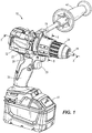
FIG. 1 is a perspective view of a portion of a hammer drill in accordance with an embodiment of the invention. -
FIG. 2 is an enlarged, exploded view of a front portion of the hammer drill ofFIG. 1 , with a collar rendered transparent to illustrate a selector ring. -
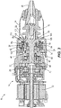
FIG. 3 is a longitudinal cross-sectional view of the hammer drill ofFIG. 1 . -
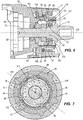
FIG. 4 is an enlarged view of the hammer drill ofFIG. 3 , with portions removed, illustrating a hammer lock-out mechanism in a disabled mode. -
FIG. 5 is a lateral cross-sectional view of the hammer lock-out mechanism ofFIG. 4 coinciding with a first rotational position of a collar of the hammer drill. -
FIG. 6 is an enlarged view of the hammer drill ofFIG. 3 , with portions removed, illustrating the hammer lock-out mechanism in an enabled mode. -
FIG. 7 is a lateral cross-sectional view of the hammer lock-out mechanism ofFIG. 6 coinciding with a second rotational position of the collar. -
FIG. 8 is a lateral cross-sectional view of the hammer lock-out mechanism coinciding with a third rotational position of the collar. -
FIG. 9 is a lateral cross-sectional view of the hammer lock-out mechanism coinciding with a fourth rotational position of the collar. -
FIG. 10 is a lateral cross-sectional view of the hammer lock-out mechanism coinciding with a fifth rotational position of the collar. -
FIG. 11 is a lateral cross-sectional view of the hammer lock-out mechanism coinciding with a sixth rotational position of the collar. -
FIG. 12 is a lateral cross-sectional view of the hammer lock-out mechanism coinciding with a seventh rotational position of the collar. -
FIG. 13 is a lateral cross-sectional view of the hammer lock-out mechanism coinciding with an eighth rotational position of the collar. -
FIG. 14 is a lateral cross-sectional view of the hammer lock-out mechanism coinciding with a ninth rotational position of the collar. -
FIG. 15 is a lateral cross-sectional view of the hammer lock-out mechanism coinciding with a tenth rotational position of the collar. -
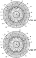
FIG. 16 is a lateral cross-sectional view of the hammer lock-out mechanism coinciding with a eleventh rotational position of the collar. -
FIG. 17 is a lateral cross-sectional view of the hammer lock-out mechanism coinciding with a twelfth rotational position of the collar. -
FIG. 18 is a lateral cross-sectional view of the hammer lock-out mechanism coinciding with a thirteenth rotational position of the collar. -
FIG. 19 is a lateral cross-sectional view of the hammer lock-out mechanism coinciding with a fourteenth rotational position of the collar. -
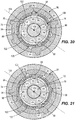
FIG. 20 is a lateral cross-sectional view of the hammer lock-out mechanism coinciding with a fifteenth rotational position of the collar. -
FIG. 21 is a lateral cross-sectional view of the hammer lock-out mechanism coinciding with a sixteenth rotational position of the collar. -
FIG. 22 is a lateral cross-sectional view of the hammer lock-out mechanism coinciding with a seventeenth rotational position of the collar. -
FIG. 23 is a lateral cross-sectional view of the hammer lock-out mechanism coinciding with an eighteenth rotational position of the collar. -
FIG. 24 is a lateral cross-sectional view of the hammer lock-out mechanism coinciding with a nineteenth rotational position of the collar. -
FIG. 25 is a lateral cross-sectional view of the hammer lock-out mechanism coinciding with a twentieth rotational position of the collar. -
FIG. 26 is a prospective view of a transmission housing of the hammer drill ofFIG. 1 , according to another embodiment of the invention. - Before any embodiments of the invention are explained in detail, it is to be understood that the invention is not limited in its application to the details of construction and the arrangement of components set forth in the following description or illustrated in the following drawings. The invention is capable of other embodiments and of being practiced or of being carried out in various ways. Also, it is to be understood that the phraseology and terminology used herein is for the purpose of description and should not be regarded as limiting.
- As shown in
FIGS. 1-3 , a rotary power tool, in this embodiment ahammer drill 10, includes ahousing 12, adrive mechanism 14 and aspindle 18 rotatable in response to receiving torque from thedrive mechanism 14. As shown inFIG. 3 , thedrive mechanism 14 includes anelectric motor 22 and amulti-speed transmission 26 between themotor 22 and thespindle 18. Thedrive mechanism 14 is at least partially enclosed by atransmission housing 30. As shown inFIGS. 1 and3 , achuck 34 is provided at the front end of thespindle 18 so as to be co-rotatable with thespindle 18. Thechuck 34 includes a plurality ofjaws 38 configured to secure a tool bit or a drill bit (not shown), such that when thedrive mechanism 14 is operated, the bit can perform a rotary and/or percussive action on a fastener or workpiece. Thehammer drill 10 includes a pistol grip handle 36, atrigger 39 for activating themotor 22, and anauxiliary handle 40 that can be selectively removed from thetransmission housing 30. Thehammer drill 10 may be powered by an on-board power source such as abattery 41 or a remote power source (e.g., an alternating current source) via a cord (not shown). - With reference to
FIGS. 2 and3 , thehammer drill 10 includes afirst ratchet 42 coupled for co-rotation with thespindle 18 and asecond ratchet 46 axially and rotationally fixed to thetransmission housing 30. In other embodiments, thesecond ratchet 46 is rotationally fixed, but axially moveable relative to thetransmission housing 30. As shown inFIGS. 3 ,4 and6 , afirst bearing 50 with anouter race 52 having anedge 54 is radially positioned between thetransmission housing 30 and thespindle 18 and supports afront portion 58 of thespindle 18. In the illustrated embodiment, theedge 54 is chamfered, but in other embodiments, the chamferededge 54 is a part separate from theouter race 52. - As shown in
FIG. 3 , thesecond ratchet 46 includes a bearingpocket 62 defined in a rear end of thesecond ratchet 46. Asecond bearing 66 is at least partially positioned in the bearingpocket 62 and supports arear portion 70 of thespindle 18. In the illustrated embodiment, thesecond bearing 66 is wholly received in the bearingpocket 62, but in other embodiments thesecond bearing 66 may at least partially extend from the bearingpocket 62. By incorporating the bearingpocket 62 in thesecond ratchet 46, thesecond bearing 66 is arranged about therear portion 70 of thespindle 18 in a nested relationship within thesecond ratchet 46, thereby reducing the overall length of thehammer drill 10 while also supporting rotation of thespindle 18. - With reference to
FIGS. 1-7 , thehammer drill 10 includes acollar 74 that is rotatably adjustable by an operator of thehammer drill 10 to shift between "hammer drill," "drill-only," and "screwdriver" modes of operation, and to select a particular clutch setting when in "screwdriver mode." Thus, thecollar 74 is conveniently provided as a single collar that can be rotated to select different operating modes of thehammer drill 10 and different clutch settings. As shown inFIGS. 2 and3 , thehammer drill 10 also includes an electronic clutch 78 capable of limiting the amount of torque that is transferred from thespindle 18 to a fastener (i.e., when in "screwdriver mode") by deactivating themotor 22 in response to a detected torque threshold or limit. Theelectronic clutch 78 includes a printed circuit board ("PCB") 82 coupled to thetransmission housing 30 and a wiper (not shown), which is coupled for co-rotation with thecollar 74. ThePCB 82 includes a plurality ofelectrical pads 86 which correspond to different clutch settings of thehammer drill 10. - The
hammer drill 10 also includes a hammer lockout mechanism 90 (FIGS. 4-7 ) for selectively inhibiting the first andsecond ratchets hammer drill 10 is in a "screwdriver mode" or a "drill-only mode." Thehammer lockout mechanism 90 includes aselector ring 94 coupled for co-rotation with and positioned inside thecollar 74, and a plurality ofballs 98 situated within corresponding radial apertures A1, A2, A3, A4, and A5 asymmetrically positioned around and extending through anannular portion 102 of thetransmission housing 30. - As shown in
FIGS. 3 ,4 , and6 , but not shown inFIG. 2 , asleeve bushing 105 is positioned on aninner surface 103 of theannular portion 102. Thebushing 105 can be formed or secured along theinner surface 103 of theannular portion 102 in a variety of ways, including but not limited to insert molding, pressing, shrink fitting, or trapping with a retaining ring or screws. Theannular portion 102 of thetransmission housing 30 is formed of a relatively soft material including but not limited to aluminum or magnesium, whereas thebushing 105 is formed of a relatively harder material than aluminum or magnesium, including but not limited to steel. In some embodiments, the relatively softer material is below 20 HRC and the relatively harder material is equal to or above 20 HRC. In other embodiments, the relatively softer material is less is below 40 HRC and the relatively harder material is equal to or above 40 HRC. - In the illustrated embodiment, the
bushing 105 is located along the length of theinner surface 103 of theannular portion 102, which includes a plurality of radially inward-extending protrusions P1-P5 extending throughsleeve bushing 105. The apertures A1-A5 respectively extend through the protrusions P1-P5 of theannular portion 102, such that the apertures A1-A5 are defined by the softer material forming the protrusions P1-P5 and the rest ofannular portion 102. Specifically, the apertures A1-A5 extend from an inner end of the protrusions P1-P5 to an outer surface of theannular portion 102. In other embodiments, the protrusions P1-P5 are omitted and the apertures A1-A5 are at least partially defined by thesleeve bushing 105. In other embodiments, the protrusions P1-P5 are omitted and thebushing 105 can be located in front of the apertures A1-A5 (i.e., with thechuck 34 located at the front of the hammer drill 10), such that no portion of thebushing 105 intersects or overlaps the apertures A1-A5, as shown inFIG. 26 . In some embodiments, thebushing 105 may extend forward along theinner surface 103 toward adistal end 107 of theannular portion 102, as shown inFIG. 26 . - In the illustrated embodiment shown in
FIGS. 4 and6 , only theball 98 in aperture A5 is shown, but each of the other apertures A1, A2, A3, and A4 also contains aball 98. As shown inFIGS. 2 ,5 and7-25 , theselector ring 94 includes a plurality of recesses R1, R2, R3, R4, and R5 asymmetrically positioned about aninner periphery 112 of theselector ring 94. The number of recesses R1-R5 corresponds to the number of apertures A1-A5 and the number ofballs 98 within the respective apertures A1-A5. - In the illustrated embodiment, five apertures A1-A5, each containing a
ball 98, are located in thetransmission housing 30 and five recesses R1-R5 are defined in theselector ring 94. However, in other embodiments, thehammer lockout mechanism 90 could employ more or fewer apertures, balls, and recesses. As shown inFIGS. 5 and7 , the five apertures A1-A5 are approximately located at 0 degrees, 55 degrees, 145 degrees, 221 degrees, and 305 degrees, respectively, measured in a counterclockwise direction from anoblique plane 104 containing alongitudinal axis 108 of thehammer drill 10 and bisecting aperture A1. As shown inFIGS. 4 and6 , thefirst ratchet 42 and thefirst bearing 50 are set within acylindrical cavity 106 defined within theannular portion 102 of thetransmission housing 30, and theselector ring 94 is radially arranged between theannular portion 102 and thecollar 74, surrounding the apertures A1-A5. - In operation, as shown in
FIGS. 4 and 5 when thecollar 74 andring 94 are rotated together to a position corresponding to a "hammer drill" mode, all five apertures A1-A5 are aligned with all five recesses R1-R5 in theselector ring 94, respectively. Therefore, when thespindle 18 is slid rearward relative to thetransmission housing 30 in response to contact with a workpiece, the chamferededge 54 of thefirst bearing 50 displaces theballs 98 situated in the respective apertures A1-A5 radially outward and partially into the recesses R1-R5, thereby disabling thehammer lockout mechanism 90. Thus, thefirst ratchet 42 is permitted to engage with thesecond ratchet 46 to impart reciprocation to thespindle 18 as it rotates. - As the
spindle 18 reciprocates during "hammer drill" mode, thefirst bearing 50 reciprocates within thecavity 106, causing theouter race 52 of thefirst bearing 50 to move along theinner surface 103 of theannular portion 102. Because theouter race 52 slides along thesleeve bushing 105, which is formed of a harder material than the rest of theannular portion 102, the longevity of thetransmission housing 30, and theinner surface 103 of theannular portion 102 in particular, is increased compared to atransmission housing 30 without thesleeve bushing 105. Through testing, it has been found that in absence of thebushing 105, thespindle 18 experiences wobble at 6,000 reciprocation cycles of thebearing 50. But, when thebushing 105 is used, thespindle 18 does not experience wobble even after 14,000 reciprocation cycles of thebearing 50. Thesleeve bushing 105 wears at a much lower rate than theinner surface 103 of theannular portion 102, thus maintaining alignment of thespindle 18 with thelongitudinal axis 108 of thehammer drill 10 throughout a longer period of the useful life of thehammer drill 10. - When the
collar 74 andselector ring 94 are incrementally rotated (e.g., by 18 degrees) in a counterclockwise direction to the second rotational position shown inFIGS. 6 and 7 , none of the apertures A1-A5 are aligned with the recesses R1-R5. Thus, in this position of thecollar 74 andselector ring 94, theballs 98 in the respective apertures A1-A5 are prevented from being radially displaced into the recesses R1-R5 in response to thespindle 18 contacting a workpiece (via thechuck 34 and an attached drill or tool bit). Rather, the chamferededge 54 of thefirst bearing 50 presses against theballs 98, which in turn abut against theinner periphery 112 of theselector ring 94 and are inhibited from displacing radially outward. Thus, thespindle 18 is prevented from moving rearward, maintaining a gap 110 between the first andsecond ratchets collar 74 and theselector ring 94, thehammer lockout mechanism 90 is enabled, preventing thespindle 18 from reciprocating in an axial manner as it is rotated by thedrive mechanism 14, operating thehammer drill 10 in a "drill only" mode. - There are a total of twenty different positions between which the
collar 74 andselector ring 94 can rotate, such that thecollar 74 is rotated 18 degrees between each of the positions. The wiper is in electrical and sliding contact with thePCB 82 as thecollar 74 is rotated between each of the twenty positions. Depending upon which of theelectrical pads 86 on thePCB 82 the wiper contacts, theelectronic clutch 78 adjusts which clutch setting to apply to themotor 22. In the "hammer drill" mode and the "drill only" mode coinciding with the first and second rotational positions of thecollar 74 andselector ring 94, respectively, theelectronic clutch 78 operates themotor 22 to output torque at a predetermined maximum value to thespindle 18. In some embodiments, the predetermined maximum value of torque output by themotor 22 may coincide with the maximum rated torque of themotor 22. - As shown in
FIG. 5 and the Table below, the "hammer drill" position of thecollar 74 corresponds to a "0 degree" or "first rotational position" position of thecollar 74, in which the recesses R1, R2, R3, R4, R5 of theselector ring 94 are respectively and approximately located at 0, 55, 145, 221, and 305 degrees counterclockwise from theplane 104, such that the apertures A1, A2, A3, A4, A5 are thereby aligned. When thecollar 74 is rotated 18 degrees counterclockwise from the "hammer drill" position to the "drill only" or "second rotational position" as shown inFIG. 7 , the recesses R1, R2, R3, R4, R5 are respectively and approximately located at 18 degrees, 73 degrees, 163 degrees, 239 degrees, and 323 degrees counterclockwise from theplane 104. - As shown in the Table below and in
FIGS. 8-25 , the operator may continue to cycle through eighteen additional rotational positions of thecollar 74, each corresponding to a different clutch setting in "screwdriver mode", by incrementally rotating thecollar 74 counterclockwise by 18 degrees each time. The first clutch setting (FIG. 8 ) provides a torque limit that is slightly less than the predetermined maximum value of torque output by themotor 22 available in the "hammer drill" mode or the "drill only" mode. As the clutch setting number numerically increases, the torque threshold applied to themotor 22 decreases, with the eighteenth clutch setting (shown inFIG. 25 ) providing the lowest torque limit to themotor 22. - As can be seen in
FIGS. 5 and7-25 , and the Table below, the "hammer drill" position inFIG. 5 is the only position in which all five apertures A1-A5 are aligned with all five recesses R1-R5, thereby disabling thehammer lockout mechanism 90 as described above. In every other setting of thecollar 74 andselector ring 94, no more than two of any of the apertures A1-A5 are aligned with the recesses R1-R5. Therefore, in "drill-only" mode (FIG. 7 ) and "screwdriver mode" (FIGS. 8-25 , clutch settings 1-18), at least threeballs 98 inhibit the rearward movement of thespindle 18, via thefirst bearing 50, thereby enabling thehammer lockout mechanism 90 and preventing axial reciprocation of thespindle 18 as it rotates.Degrees of collar rotation A1 A2 A3 A4 A5 Balls in recesses Mode/Clutch Setting Figure Aperture is aligned with which recess? 0 R1 R2 R3 R4 R5 5 Hammer Drill 5 18 - - - - - 0 Drill Only 7 36 - - - - - 0 1 8 54 R5 R1 - - - 2 2 9 72 - - - R3 R4 2 3 10 90 - - R2 - R4 2 4 11 108 - R5 - - - 1 5 12 126 - - - - - 0 6 13 144 R4 - R1 - - 2 7 14 162 - - - R2 R3 2 8 15 180 - - - - - 0 9 16 198 - R4 R5 - - 2 10 17 216 R3 - - R1 - 2 11 18 234 - - - - - 0 12 19 252 - - - - R2 1 13 20 270 - R3 - R5 - 2 14 21 288 - - R4 R5 - 2 15 22 306 R2 - - - R1 2 16 23 324 - - - - - 0 17 24 342 - - - - - 0 18 25 360 R1 R2 R3 R4 R5 5 Hammer Drill 5 - To adjust the
hammer drill 10 between "screwdriver" mode, "drill only" mode, and "hammer drill" mode, thecollar 74 may be rotated a full 360 degrees and beyond in a single rotational direction, clockwise or counterclockwise, without any stops which would otherwise limit the extent to which thecollar 74 may be rotated. Therefore, if the operator is using thehammer drill 10 in "screwdriver mode" on the eighteenth clutch setting (FIG. 25 ), the operator needs only to rotate thecollar 74 counterclockwise by an additional 18 degrees to switch thehammer drill 10 into "hammer drill" mode, rather than rotating thecollar 74 in an opposite (clockwise) direction back through clutch settings 17 to 1 and "drill only" mode. - Various features of the invention are set forth in the following claims.
Claims (15)
- A rotary power tool comprising:a drive mechanism including an electric motor and a transmission;a housing enclosing at least a portion of the drive mechanism;a spindle rotatable in response to receiving torque from the drive mechanism;a first ratchet coupled for co-rotation with the spindle;a second ratchet rotationally fixed to the housing;a sleeve bushing on an interior of the housing; anda bearing arranged between the spindle and the sleeve bushing and rotatably supporting the spindle, the bearing having an outer race,wherein the spindle is movable relative to the housing in response to contact with a workpiece, causing the first and second ratchets to engage and the spindle to reciprocate while rotating,and wherein the outer race of the bearing moves along the sleeve bushing during reciprocation of the spindle when the first ratchet and second ratchet are engaged.
- The rotary power tool of claim 1, wherein the sleeve bushing is formed of steel.
- The rotary power tool of claim 1 or 2, wherein the housing is at least partially formed of aluminum.
- The rotary power tool of any preceding claim, wherein the sleeve bushing is i) insert molded with the housing; ii) press fit with the housing; or iii) shrink fit with the housing.
- The rotary power tool of any preceding claim, further comprising a hammer lockout mechanism adjustable between a first mode and a second mode, the hammer lockout mechanism including an aperture in the housing and a detent movable within the aperture between a locking position and an unlocking position,
wherein, in the first mode, the detent is moveable from the locking position to the unlocking position, such that the spindle is movable relative to the housing in response to contact with a workpiece, causing the first and second ratchets to engage, and
wherein, in the second mode, the detent is prevented from moving from the locking position to the unlocking position, such that the spindle is blocked by the detent from moving relative to the housing in response to contact with a workpiece and a gap is maintained between the first and second ratchets. - The rotary power tool of claim 5, wherein
the aperture extends through the sleeve bushing; and/or
the housing includes a radially inward-extending protrusion extending through the sleeve bushing, and wherein the aperture extends through the protrusion. - The rotary power tool of claim 5 or 6, wherein
the sleeve bushing is formed of a first material and the housing is formed of second material that is softer than the first material; and/or
wherein the bushing is arranged in front of the aperture, such that no portion of the bushing intersects the aperture. - A rotary power tool according to claim 1, wherein the housing includes a protrusion extending through the sleeve bushing;
the rotary power tool further comprising:a hammer lockout mechanism adjustable between a first mode and a second mode, the hammer lockout mechanism includingan aperture extending through the protrusion, anda ball movable within the aperture between a locking position and an unlocking position,wherein, in the first mode, the ball is moveable from the locking position to the unlocking position, such that the spindle is movable relative to the housing in response to contact with a workpiece, causing the first and second ratchets to engage and the spindle to reciprocate while rotating,
andwherein, in the second mode, the ball is prevented from moving from the locking position to the unlocking position, such that the spindle is blocked by the ball from moving relative to the housing in response to contact with a workpiece and a gap is maintained between the first and second ratchets. - The rotary power tool of claim 8, wherein the sleeve bushing is formed of steel.
- The rotary power tool of claim 8 or 9, wherein the housing is at least partially formed of aluminum.
- The rotary power tool of any of claims 8 to 10, wherein the sleeve bushing is i) insert molded with the housing or ii) press fit with the housing.
- The rotary power tool of any of claims 8 to 11, wherein the sleeve bushing is formed of a first material and the housing is formed of second material that is softer than the first material, and wherein the aperture in the housing is defined by the second material.
- A rotary power tool according to claim 1, wherein the housing includes a plurality of protrusions extending through the sleeve bushing;
the rotary power tool further comprising:a hammer lockout mechanism adjustable between a first mode and a second mode, the hammer lockout mechanism including:a plurality of apertures, each aperture extending through one of the plurality of protrusions, anda ball arranged in each aperture, each ball moveable between a locking position and an unlocking position,wherein, in the first mode, each of the balls is moveable from the locking position to the unlocking position, such that the spindle is movable relative to the housing in response to contact with a workpiece, causing the first and second ratchets to engage and the spindle to reciprocate while rotating; andwherein, in the second mode, at least one of the balls is prevented from moving from the locking position to the unlocking position, such that the spindle is blocked by one or more balls from moving relative to the housing in response to contact with a workpiece and a gap is maintained between the first and second ratchets. - The rotary power tool of claim 13, wherein the sleeve bushing is i) insert molded with the housing; or ii) press fit with the housing.
- The rotary power tool of claim 13 or 14, wherein the sleeve bushing is formed of a first material and the housing is formed of second material that is softer than the first material, and wherein the aperture in the housing is defined by the second material.
Applications Claiming Priority (1)
| Application Number | Priority Date | Filing Date | Title |
|---|---|---|---|
| US201862650741P | 2018-03-30 | 2018-03-30 |
Publications (2)
| Publication Number | Publication Date |
|---|---|
| EP3546131A1 true EP3546131A1 (en) | 2019-10-02 |
| EP3546131B1 EP3546131B1 (en) | 2024-10-09 |
Family
ID=66041337
Family Applications (1)
| Application Number | Title | Priority Date | Filing Date |
|---|---|---|---|
| EP19166384.8A Active EP3546131B1 (en) | 2018-03-30 | 2019-03-29 | Rotary power tool including transmission housing bushing |
Country Status (3)
| Country | Link |
|---|---|
| US (3) | US11148273B2 (en) |
| EP (1) | EP3546131B1 (en) |
| CN (1) | CN210081645U (en) |
Cited By (1)
| Publication number | Priority date | Publication date | Assignee | Title |
|---|---|---|---|---|
| GB2617901A (en) * | 2020-04-28 | 2023-10-25 | Snap On Incorporated | Quick change indexable ratchet head |
Families Citing this family (6)
| Publication number | Priority date | Publication date | Assignee | Title |
|---|---|---|---|---|
| US11148273B2 (en) * | 2018-03-30 | 2021-10-19 | Milwaukee Electric Tool Corporation | Rotary power tool including transmission housing bushing |
| EP3808478B1 (en) * | 2019-10-14 | 2022-04-06 | Nanjing Chervon Industry Co., Ltd. | Impact drill |
| DE102020203832A1 (en) * | 2020-03-25 | 2021-09-30 | Robert Bosch Gesellschaft mit beschränkter Haftung | Hand machine tool with a notch mechanism |
| CN214446110U (en) * | 2020-06-30 | 2021-10-22 | 南京德朔实业有限公司 | Power tool system and tool attachment device |
| US11964376B2 (en) * | 2020-09-24 | 2024-04-23 | Techtronic Cordless Gp | Multi-function handheld electric tool |
| US20240139916A1 (en) * | 2022-11-01 | 2024-05-02 | Milwaukee Electric Tool Corporation | Impact tool including an electronic clutch |
Citations (4)
| Publication number | Priority date | Publication date | Assignee | Title |
|---|---|---|---|---|
| US3511321A (en) * | 1968-09-04 | 1970-05-12 | Milwaukee Electric Tool Corp | Hammer drill |
| DE2941355A1 (en) * | 1979-10-12 | 1981-04-23 | Licentia Patent-Verwaltungs-Gmbh, 6000 Frankfurt | Impact drill striker mechanism - has three bolts guiding body and springs |
| US20120111594A1 (en) * | 2009-06-26 | 2012-05-10 | Tobias Herr | Hand-held power tool |
| EP2803449A1 (en) * | 2013-05-14 | 2014-11-19 | Black & Decker Inc. | Clutch and hammer assemblies for power tool |
Family Cites Families (19)
| Publication number | Priority date | Publication date | Assignee | Title |
|---|---|---|---|---|
| DE2105336A1 (en) | 1971-02-05 | 1972-08-10 | Bosch Gmbh Robert | Bearing bridge in the gearbox of a power tool |
| DE3239283A1 (en) * | 1981-11-13 | 1983-05-19 | Black & Decker, Inc., 19711 Newark, Del. | MOTOR DRIVEN TOOL, ESPECIALLY ELECTRIC TOOL WITH A PLASTIC HOUSING |
| GB9304540D0 (en) * | 1993-03-05 | 1993-04-21 | Black & Decker Inc | Power tool and mechanism |
| GB9309054D0 (en) * | 1993-05-01 | 1993-06-16 | Black & Decker Inc | Power tools and hammer mechanisms therefor |
| JP3711877B2 (en) | 2001-03-02 | 2005-11-02 | 日立工機株式会社 | Electric tool |
| DE10242738A1 (en) | 2002-09-13 | 2005-01-20 | Robert Bosch Gmbh | Hand tool machine, in particular angle grinder |
| TW556637U (en) | 2003-02-24 | 2003-10-01 | Mobiletron Electronics Co Ltd | Power tool |
| EP1813008B1 (en) | 2004-11-19 | 2017-02-01 | LG Electronics Inc. | A motor in which an electric leakage to a shaft is prevented |
| EP1703618B1 (en) | 2005-03-14 | 2013-05-15 | Kaeser Kompressoren AG | Air-cooled electric motor |
| CN101752935B (en) | 2008-12-03 | 2011-07-20 | 中山大洋电机股份有限公司 | A casing structure of an outer rotor motor and a rotor component manufactured using the casing |
| US8633385B2 (en) | 2010-11-09 | 2014-01-21 | Hubbell Incorporated | Weatherproof cover having bidirectional hinge |
| DE102012201593A1 (en) | 2012-02-03 | 2013-08-08 | Robert Bosch Gmbh | Hand machine tool device |
| CN204686830U (en) * | 2012-10-19 | 2015-10-07 | 米沃奇电动工具公司 | Hammer drill |
| WO2016066745A2 (en) * | 2014-10-29 | 2016-05-06 | Gwf Messsysteme Ag | Wheel and method for producing said wheel |
| DE102014225945A1 (en) | 2014-12-15 | 2016-06-30 | Robert Bosch Gmbh | Electric machine with a fan driven by a gearbox |
| CN105245058A (en) | 2015-11-13 | 2016-01-13 | 泰信电机(苏州)有限公司 | Heat sink for variable frequency motor |
| CN205141921U (en) | 2015-11-13 | 2016-04-06 | 泰信电机(苏州)有限公司 | Heat radiator for be used for inverter motor |
| WO2018204741A1 (en) * | 2017-05-05 | 2018-11-08 | Milwaukee Electric Tool Corporation | Power tool |
| US11148273B2 (en) * | 2018-03-30 | 2021-10-19 | Milwaukee Electric Tool Corporation | Rotary power tool including transmission housing bushing |
-
2019
- 2019-03-21 US US16/360,585 patent/US11148273B2/en active Active
- 2019-03-29 EP EP19166384.8A patent/EP3546131B1/en active Active
- 2019-04-01 CN CN201920447774.7U patent/CN210081645U/en active Active
-
2021
- 2021-09-17 US US17/477,762 patent/US11440173B2/en active Active
-
2022
- 2022-09-07 US US17/939,031 patent/US12202115B2/en active Active
Patent Citations (4)
| Publication number | Priority date | Publication date | Assignee | Title |
|---|---|---|---|---|
| US3511321A (en) * | 1968-09-04 | 1970-05-12 | Milwaukee Electric Tool Corp | Hammer drill |
| DE2941355A1 (en) * | 1979-10-12 | 1981-04-23 | Licentia Patent-Verwaltungs-Gmbh, 6000 Frankfurt | Impact drill striker mechanism - has three bolts guiding body and springs |
| US20120111594A1 (en) * | 2009-06-26 | 2012-05-10 | Tobias Herr | Hand-held power tool |
| EP2803449A1 (en) * | 2013-05-14 | 2014-11-19 | Black & Decker Inc. | Clutch and hammer assemblies for power tool |
Cited By (2)
| Publication number | Priority date | Publication date | Assignee | Title |
|---|---|---|---|---|
| GB2617901A (en) * | 2020-04-28 | 2023-10-25 | Snap On Incorporated | Quick change indexable ratchet head |
| GB2617901B (en) * | 2020-04-28 | 2024-04-03 | Snap On Incorporated | Quick change indexable ratchet head |
Also Published As
| Publication number | Publication date |
|---|---|
| US20190299383A1 (en) | 2019-10-03 |
| US11440173B2 (en) | 2022-09-13 |
| US12202115B2 (en) | 2025-01-21 |
| EP3546131B1 (en) | 2024-10-09 |
| US20230017720A1 (en) | 2023-01-19 |
| US20220009071A1 (en) | 2022-01-13 |
| CN210081645U (en) | 2020-02-18 |
| US11148273B2 (en) | 2021-10-19 |
Similar Documents
| Publication | Publication Date | Title |
|---|---|---|
| US11440173B2 (en) | Rotary power tool including transmission housing bushing | |
| US12083661B2 (en) | Power tool | |
| CN103042508A (en) | Tool attachment | |
| US9308630B2 (en) | Impact screwdriver | |
| GB2383289A (en) | Tool with collar and side handle | |
| US20110278034A1 (en) | Portable angle impact tool | |
| US20130081517A1 (en) | Multi-head Ratchet Sleeve Spanner | |
| CN102476367B (en) | Power tool | |
| US20110278036A1 (en) | Portable angle impact tool | |
| US12240094B2 (en) | Multi-function handheld electric tool | |
| GB2480351A (en) | Portable angled impact tool with switch assembly | |
| CN201881359U (en) | Power tool | |
| JP2024027576A (en) | screwdriver | |
| KR102533152B1 (en) | Electric Tool | |
| CN220144788U (en) | Electric tailstock of lathe | |
| US20250162122A1 (en) | Power tool | |
| US20250170694A1 (en) | Bulk metallic glass components for a power tool |
Legal Events
| Date | Code | Title | Description |
|---|---|---|---|
| PUAI | Public reference made under article 153(3) epc to a published international application that has entered the european phase |
Free format text: ORIGINAL CODE: 0009012 |
|
| STAA | Information on the status of an ep patent application or granted ep patent |
Free format text: STATUS: THE APPLICATION HAS BEEN PUBLISHED |
|
| AK | Designated contracting states |
Kind code of ref document: A1 Designated state(s): AL AT BE BG CH CY CZ DE DK EE ES FI FR GB GR HR HU IE IS IT LI LT LU LV MC MK MT NL NO PL PT RO RS SE SI SK SM TR |
|
| AX | Request for extension of the european patent |
Extension state: BA ME |
|
| STAA | Information on the status of an ep patent application or granted ep patent |
Free format text: STATUS: REQUEST FOR EXAMINATION WAS MADE |
|
| 17P | Request for examination filed |
Effective date: 20200402 |
|
| RBV | Designated contracting states (corrected) |
Designated state(s): AL AT BE BG CH CY CZ DE DK EE ES FI FR GB GR HR HU IE IS IT LI LT LU LV MC MK MT NL NO PL PT RO RS SE SI SK SM TR |
|
| STAA | Information on the status of an ep patent application or granted ep patent |
Free format text: STATUS: EXAMINATION IS IN PROGRESS |
|
| 17Q | First examination report despatched |
Effective date: 20220519 |
|
| GRAP | Despatch of communication of intention to grant a patent |
Free format text: ORIGINAL CODE: EPIDOSNIGR1 |
|
| STAA | Information on the status of an ep patent application or granted ep patent |
Free format text: STATUS: GRANT OF PATENT IS INTENDED |
|
| INTG | Intention to grant announced |
Effective date: 20240507 |
|
| GRAS | Grant fee paid |
Free format text: ORIGINAL CODE: EPIDOSNIGR3 |
|
| GRAA | (expected) grant |
Free format text: ORIGINAL CODE: 0009210 |
|
| STAA | Information on the status of an ep patent application or granted ep patent |
Free format text: STATUS: THE PATENT HAS BEEN GRANTED |
|
| AK | Designated contracting states |
Kind code of ref document: B1 Designated state(s): AL AT BE BG CH CY CZ DE DK EE ES FI FR GB GR HR HU IE IS IT LI LT LU LV MC MK MT NL NO PL PT RO RS SE SI SK SM TR |
|
| REG | Reference to a national code |
Ref country code: CH Ref legal event code: EP |
|
| REG | Reference to a national code |
Ref country code: DE Ref legal event code: R096 Ref document number: 602019059932 Country of ref document: DE |
|
| REG | Reference to a national code |
Ref country code: IE Ref legal event code: FG4D |
|
| REG | Reference to a national code |
Ref country code: LT Ref legal event code: MG9D |
|
| REG | Reference to a national code |
Ref country code: NL Ref legal event code: MP Effective date: 20241009 |
|
| REG | Reference to a national code |
Ref country code: AT Ref legal event code: MK05 Ref document number: 1730076 Country of ref document: AT Kind code of ref document: T Effective date: 20241009 |
|
| PG25 | Lapsed in a contracting state [announced via postgrant information from national office to epo] |
Ref country code: NL Free format text: LAPSE BECAUSE OF FAILURE TO SUBMIT A TRANSLATION OF THE DESCRIPTION OR TO PAY THE FEE WITHIN THE PRESCRIBED TIME-LIMIT Effective date: 20241009 |
|
| PG25 | Lapsed in a contracting state [announced via postgrant information from national office to epo] |
Ref country code: NL Free format text: LAPSE BECAUSE OF FAILURE TO SUBMIT A TRANSLATION OF THE DESCRIPTION OR TO PAY THE FEE WITHIN THE PRESCRIBED TIME-LIMIT Effective date: 20241009 |
|
| PG25 | Lapsed in a contracting state [announced via postgrant information from national office to epo] |
Ref country code: HR Free format text: LAPSE BECAUSE OF FAILURE TO SUBMIT A TRANSLATION OF THE DESCRIPTION OR TO PAY THE FEE WITHIN THE PRESCRIBED TIME-LIMIT Effective date: 20241009 Ref country code: IS Free format text: LAPSE BECAUSE OF FAILURE TO SUBMIT A TRANSLATION OF THE DESCRIPTION OR TO PAY THE FEE WITHIN THE PRESCRIBED TIME-LIMIT Effective date: 20250209 Ref country code: PT Free format text: LAPSE BECAUSE OF FAILURE TO SUBMIT A TRANSLATION OF THE DESCRIPTION OR TO PAY THE FEE WITHIN THE PRESCRIBED TIME-LIMIT Effective date: 20250210 |
|
| PG25 | Lapsed in a contracting state [announced via postgrant information from national office to epo] |
Ref country code: FI Free format text: LAPSE BECAUSE OF FAILURE TO SUBMIT A TRANSLATION OF THE DESCRIPTION OR TO PAY THE FEE WITHIN THE PRESCRIBED TIME-LIMIT Effective date: 20241009 |
|
| PG25 | Lapsed in a contracting state [announced via postgrant information from national office to epo] |
Ref country code: BG Free format text: LAPSE BECAUSE OF FAILURE TO SUBMIT A TRANSLATION OF THE DESCRIPTION OR TO PAY THE FEE WITHIN THE PRESCRIBED TIME-LIMIT Effective date: 20241009 |
|
| PG25 | Lapsed in a contracting state [announced via postgrant information from national office to epo] |
Ref country code: ES Free format text: LAPSE BECAUSE OF FAILURE TO SUBMIT A TRANSLATION OF THE DESCRIPTION OR TO PAY THE FEE WITHIN THE PRESCRIBED TIME-LIMIT Effective date: 20241009 |
|
| PG25 | Lapsed in a contracting state [announced via postgrant information from national office to epo] |
Ref country code: NO Free format text: LAPSE BECAUSE OF FAILURE TO SUBMIT A TRANSLATION OF THE DESCRIPTION OR TO PAY THE FEE WITHIN THE PRESCRIBED TIME-LIMIT Effective date: 20250109 |
|
| PG25 | Lapsed in a contracting state [announced via postgrant information from national office to epo] |
Ref country code: LV Free format text: LAPSE BECAUSE OF FAILURE TO SUBMIT A TRANSLATION OF THE DESCRIPTION OR TO PAY THE FEE WITHIN THE PRESCRIBED TIME-LIMIT Effective date: 20241009 Ref country code: GR Free format text: LAPSE BECAUSE OF FAILURE TO SUBMIT A TRANSLATION OF THE DESCRIPTION OR TO PAY THE FEE WITHIN THE PRESCRIBED TIME-LIMIT Effective date: 20250110 Ref country code: AT Free format text: LAPSE BECAUSE OF FAILURE TO SUBMIT A TRANSLATION OF THE DESCRIPTION OR TO PAY THE FEE WITHIN THE PRESCRIBED TIME-LIMIT Effective date: 20241009 |
|
| PG25 | Lapsed in a contracting state [announced via postgrant information from national office to epo] |
Ref country code: PL Free format text: LAPSE BECAUSE OF FAILURE TO SUBMIT A TRANSLATION OF THE DESCRIPTION OR TO PAY THE FEE WITHIN THE PRESCRIBED TIME-LIMIT Effective date: 20241009 |
|
| PG25 | Lapsed in a contracting state [announced via postgrant information from national office to epo] |
Ref country code: RS Free format text: LAPSE BECAUSE OF FAILURE TO SUBMIT A TRANSLATION OF THE DESCRIPTION OR TO PAY THE FEE WITHIN THE PRESCRIBED TIME-LIMIT Effective date: 20250109 |
|
| PG25 | Lapsed in a contracting state [announced via postgrant information from national office to epo] |
Ref country code: SM Free format text: LAPSE BECAUSE OF FAILURE TO SUBMIT A TRANSLATION OF THE DESCRIPTION OR TO PAY THE FEE WITHIN THE PRESCRIBED TIME-LIMIT Effective date: 20241009 |
|
| PG25 | Lapsed in a contracting state [announced via postgrant information from national office to epo] |
Ref country code: DK Free format text: LAPSE BECAUSE OF FAILURE TO SUBMIT A TRANSLATION OF THE DESCRIPTION OR TO PAY THE FEE WITHIN THE PRESCRIBED TIME-LIMIT Effective date: 20241009 |
|
| REG | Reference to a national code |
Ref country code: DE Ref legal event code: R097 Ref document number: 602019059932 Country of ref document: DE |
|
| PG25 | Lapsed in a contracting state [announced via postgrant information from national office to epo] |
Ref country code: EE Free format text: LAPSE BECAUSE OF FAILURE TO SUBMIT A TRANSLATION OF THE DESCRIPTION OR TO PAY THE FEE WITHIN THE PRESCRIBED TIME-LIMIT Effective date: 20241009 |
|
| PG25 | Lapsed in a contracting state [announced via postgrant information from national office to epo] |
Ref country code: RO Free format text: LAPSE BECAUSE OF FAILURE TO SUBMIT A TRANSLATION OF THE DESCRIPTION OR TO PAY THE FEE WITHIN THE PRESCRIBED TIME-LIMIT Effective date: 20241009 |
|
| PG25 | Lapsed in a contracting state [announced via postgrant information from national office to epo] |
Ref country code: SK Free format text: LAPSE BECAUSE OF FAILURE TO SUBMIT A TRANSLATION OF THE DESCRIPTION OR TO PAY THE FEE WITHIN THE PRESCRIBED TIME-LIMIT Effective date: 20241009 |
|
| PG25 | Lapsed in a contracting state [announced via postgrant information from national office to epo] |
Ref country code: CZ Free format text: LAPSE BECAUSE OF FAILURE TO SUBMIT A TRANSLATION OF THE DESCRIPTION OR TO PAY THE FEE WITHIN THE PRESCRIBED TIME-LIMIT Effective date: 20241009 |
|
| PG25 | Lapsed in a contracting state [announced via postgrant information from national office to epo] |
Ref country code: IT Free format text: LAPSE BECAUSE OF FAILURE TO SUBMIT A TRANSLATION OF THE DESCRIPTION OR TO PAY THE FEE WITHIN THE PRESCRIBED TIME-LIMIT Effective date: 20241009 |
|
| PLBE | No opposition filed within time limit |
Free format text: ORIGINAL CODE: 0009261 |
|
| STAA | Information on the status of an ep patent application or granted ep patent |
Free format text: STATUS: NO OPPOSITION FILED WITHIN TIME LIMIT |
|
| PG25 | Lapsed in a contracting state [announced via postgrant information from national office to epo] |
Ref country code: SE Free format text: LAPSE BECAUSE OF FAILURE TO SUBMIT A TRANSLATION OF THE DESCRIPTION OR TO PAY THE FEE WITHIN THE PRESCRIBED TIME-LIMIT Effective date: 20241009 |
|
| 26N | No opposition filed |
Effective date: 20250710 |
|
| PG25 | Lapsed in a contracting state [announced via postgrant information from national office to epo] |
Ref country code: MC Free format text: LAPSE BECAUSE OF FAILURE TO SUBMIT A TRANSLATION OF THE DESCRIPTION OR TO PAY THE FEE WITHIN THE PRESCRIBED TIME-LIMIT Effective date: 20241009 |
|
| REG | Reference to a national code |
Ref country code: CH Ref legal event code: H13 Free format text: ST27 STATUS EVENT CODE: U-0-0-H10-H13 (AS PROVIDED BY THE NATIONAL OFFICE) Effective date: 20251023 |
|
| PG25 | Lapsed in a contracting state [announced via postgrant information from national office to epo] |
Ref country code: LU Free format text: LAPSE BECAUSE OF NON-PAYMENT OF DUE FEES Effective date: 20250329 |
|
| GBPC | Gb: european patent ceased through non-payment of renewal fee |
Effective date: 20250329 |
|
| REG | Reference to a national code |
Ref country code: BE Ref legal event code: MM Effective date: 20250331 |
|
| PG25 | Lapsed in a contracting state [announced via postgrant information from national office to epo] |
Ref country code: GB Free format text: LAPSE BECAUSE OF NON-PAYMENT OF DUE FEES Effective date: 20250329 |
|
| PG25 | Lapsed in a contracting state [announced via postgrant information from national office to epo] |
Ref country code: FR Free format text: LAPSE BECAUSE OF NON-PAYMENT OF DUE FEES Effective date: 20250331 |
|
| PG25 | Lapsed in a contracting state [announced via postgrant information from national office to epo] |
Ref country code: BE Free format text: LAPSE BECAUSE OF NON-PAYMENT OF DUE FEES Effective date: 20250331 |
|
| PG25 | Lapsed in a contracting state [announced via postgrant information from national office to epo] |
Ref country code: CH Free format text: LAPSE BECAUSE OF NON-PAYMENT OF DUE FEES Effective date: 20250331 |
|
| PG25 | Lapsed in a contracting state [announced via postgrant information from national office to epo] |
Ref country code: IE Free format text: LAPSE BECAUSE OF NON-PAYMENT OF DUE FEES Effective date: 20250329 |
|
| PGFP | Annual fee paid to national office [announced via postgrant information from national office to epo] |
Ref country code: DE Payment date: 20260327 Year of fee payment: 8 |
|
| PG25 | Lapsed in a contracting state [announced via postgrant information from national office to epo] |
Ref country code: CY Free format text: LAPSE BECAUSE OF FAILURE TO SUBMIT A TRANSLATION OF THE DESCRIPTION OR TO PAY THE FEE WITHIN THE PRESCRIBED TIME-LIMIT Effective date: 20241009 |
|
| PG25 | Lapsed in a contracting state [announced via postgrant information from national office to epo] |
Ref country code: LT Free format text: LAPSE BECAUSE OF FAILURE TO SUBMIT A TRANSLATION OF THE DESCRIPTION OR TO PAY THE FEE WITHIN THE PRESCRIBED TIME-LIMIT Effective date: 20241009 |
|
| PG25 | Lapsed in a contracting state [announced via postgrant information from national office to epo] |
Ref country code: TR Free format text: LAPSE BECAUSE OF FAILURE TO SUBMIT A TRANSLATION OF THE DESCRIPTION OR TO PAY THE FEE WITHIN THE PRESCRIBED TIME-LIMIT Effective date: 20241009 |