EP3546128A1 - Nail gun - Google Patents
Nail gun Download PDFInfo
- Publication number
- EP3546128A1 EP3546128A1 EP19165297.3A EP19165297A EP3546128A1 EP 3546128 A1 EP3546128 A1 EP 3546128A1 EP 19165297 A EP19165297 A EP 19165297A EP 3546128 A1 EP3546128 A1 EP 3546128A1
- Authority
- EP
- European Patent Office
- Prior art keywords
- nail
- module
- gun
- pressure
- detection member
- Prior art date
- Legal status (The legal status is an assumption and is not a legal conclusion. Google has not performed a legal analysis and makes no representation as to the accuracy of the status listed.)
- Granted
Links
- 238000001514 detection method Methods 0.000 claims abstract description 52
- 238000007789 sealing Methods 0.000 claims abstract description 26
- 238000010304 firing Methods 0.000 claims description 18
- 230000000903 blocking effect Effects 0.000 claims description 7
- 230000003213 activating effect Effects 0.000 description 3
- 230000002265 prevention Effects 0.000 description 2
- 230000000994 depressogenic effect Effects 0.000 description 1
- 230000004048 modification Effects 0.000 description 1
- 238000012986 modification Methods 0.000 description 1
- 230000000717 retained effect Effects 0.000 description 1
Images


Classifications
-
- B—PERFORMING OPERATIONS; TRANSPORTING
- B25—HAND TOOLS; PORTABLE POWER-DRIVEN TOOLS; MANIPULATORS
- B25C—HAND-HELD NAILING OR STAPLING TOOLS; MANUALLY OPERATED PORTABLE STAPLING TOOLS
- B25C1/00—Hand-held nailing tools; Nail feeding devices
- B25C1/04—Hand-held nailing tools; Nail feeding devices operated by fluid pressure, e.g. by air pressure
- B25C1/041—Hand-held nailing tools; Nail feeding devices operated by fluid pressure, e.g. by air pressure with fixed main cylinder
- B25C1/043—Trigger valve and trigger mechanism
-
- B—PERFORMING OPERATIONS; TRANSPORTING
- B25—HAND TOOLS; PORTABLE POWER-DRIVEN TOOLS; MANIPULATORS
- B25C—HAND-HELD NAILING OR STAPLING TOOLS; MANUALLY OPERATED PORTABLE STAPLING TOOLS
- B25C1/00—Hand-held nailing tools; Nail feeding devices
- B25C1/008—Safety devices
-
- B—PERFORMING OPERATIONS; TRANSPORTING
- B25—HAND TOOLS; PORTABLE POWER-DRIVEN TOOLS; MANIPULATORS
- B25C—HAND-HELD NAILING OR STAPLING TOOLS; MANUALLY OPERATED PORTABLE STAPLING TOOLS
- B25C1/00—Hand-held nailing tools; Nail feeding devices
- B25C1/001—Nail feeding devices
- B25C1/005—Nail feeding devices for rows of contiguous nails
-
- B—PERFORMING OPERATIONS; TRANSPORTING
- B25—HAND TOOLS; PORTABLE POWER-DRIVEN TOOLS; MANIPULATORS
- B25C—HAND-HELD NAILING OR STAPLING TOOLS; MANUALLY OPERATED PORTABLE STAPLING TOOLS
- B25C1/00—Hand-held nailing tools; Nail feeding devices
- B25C1/04—Hand-held nailing tools; Nail feeding devices operated by fluid pressure, e.g. by air pressure
- B25C1/047—Mechanical details
-
- B—PERFORMING OPERATIONS; TRANSPORTING
- B25—HAND TOOLS; PORTABLE POWER-DRIVEN TOOLS; MANIPULATORS
- B25C—HAND-HELD NAILING OR STAPLING TOOLS; MANUALLY OPERATED PORTABLE STAPLING TOOLS
- B25C1/00—Hand-held nailing tools; Nail feeding devices
- B25C1/08—Hand-held nailing tools; Nail feeding devices operated by combustion pressure
- B25C1/10—Hand-held nailing tools; Nail feeding devices operated by combustion pressure generated by detonation of a cartridge
- B25C1/18—Details and accessories, e.g. splinter guards, spall minimisers
- B25C1/182—Feeding devices
- B25C1/184—Feeding devices for nails
-
- B—PERFORMING OPERATIONS; TRANSPORTING
- B25—HAND TOOLS; PORTABLE POWER-DRIVEN TOOLS; MANIPULATORS
- B25C—HAND-HELD NAILING OR STAPLING TOOLS; MANUALLY OPERATED PORTABLE STAPLING TOOLS
- B25C1/00—Hand-held nailing tools; Nail feeding devices
- B25C1/08—Hand-held nailing tools; Nail feeding devices operated by combustion pressure
- B25C1/10—Hand-held nailing tools; Nail feeding devices operated by combustion pressure generated by detonation of a cartridge
- B25C1/18—Details and accessories, e.g. splinter guards, spall minimisers
- B25C1/188—Arrangements at the forward end of the barrel, e.g. splinter guards, spall minimisers, safety arrangements, silencers, bolt retainers
Definitions
- the disclosure relates to a nail gun, and more particularly to a nail gun that is prevented from dry-firing.
- Taiwanese Patent No. 1349600 discloses a conventional nail gun that includes a dry-firing prevention module.
- the dry-firing prevention module includes a valve member that is resiliently biased for sealing a release chamber, a rod member that is movable along a path of movement and that abuts against the valve member, a stop member that is pivoted to a magazine housing receiving nails therein, and a nail pusher that is movably mounted to the magazine housing and that pushes the nails in the magazine housing.
- the nail pusher is spaced apart from the stop member, and the stop member is resiliently retained on the path of movement of the rod member and abuts against the rod member.
- the stop member hinders movement of the rod member and the valve member so that the valve member is maintained at an unblocking position where the valve member unseals the release chamber to permit high-pressure air to be released from the release chamber for firing a nail.
- the nail pusher pushes the stop member to remove the stop member from the path of movement of the rod member.
- the rod member and the valve member are biased so that an end of the rod member moves past the stop member and that the valve member is moved to a blocking position where the valve member seals the release chamber to prevent the release of the high-pressure air from the release chamber, thereby preventing the firing of the nails.
- valve member cannot be moved from the blocking position to the unblocking position to permit the firing of the nails again by the stop member since the end of the rod member has moved past the stop member when the stop member is removed from the path of movement of the rod member.
- An additional mechanism is needed for moving the valve member from the blocking position to the unblocking position.
- an object of the disclosure is to provide a nail gun that can alleviate the drawback of the prior art.
- the nail gun includes a gun body, a power module, a muzzle module, a magazine module, a firing module and a detection module.
- the power module is disposed in the gun body.
- the power module is configured to perform a nail-driving operation in which the power module outputs a striking force to strike a nail by receiving a first pressure, and is prevented from receiving the first pressure when the power module is subjected to a second pressure.
- the muzzle module is mounted to the gun body, and defines a nail exit opening.
- the magazine module is connected to the muzzle module for pushing a plurality of nails to move into the muzzle module one at a time.
- the firing module is mounted to the gun body, and operable to activate the nail-driving operation for firing the nails via the nail exit opening.
- the detection module includes a valve rod that is movably mounted to the gun body for controlling the second pressure, and a detection member that is pivoted to the magazine module and that is operable to pivot between an unsealing position and a sealing position. The detection member is moved to the sealing position when the number of the nails in the magazine module is less than a predetermined amount. When the detection member is at the unsealing position, the valve rod is moved away from the detection member to permit release of the second pressure. When the detection member is at the sealing position, the valve rod is moved toward the detection member to prevent the second pressure from being released.
- the embodiment of the nail gun includes a gun body 1, a power module 2, a muzzle module 3, a magazine module 5, a firing module 6 and a detection module 7.
- the gun body 1 has a handle 101.
- a distal portion of the handle 101 is denoted as the lower portion of the nail gun
- the muzzle module 3 is denoted as the front portion of the nail gun, and the rest can be deduced by analogy.
- the gun body 1 further has a release flow path 11 that is in communication with the outside of the nail gun and that is disposed adjacent to the magazine module 5, an intake channel 12 that is for introducing high-pressure air into the nail gun to form a first pressure, and a connecting flow path 13 (see Figure 5 ) that is in communication with the release flow path 11.
- the release flow path 11 has a small-diameter section 111, and a large-diameter section 112 that has a diameter larger than that of the small-diameter section 111.
- the power module 2 is disposed in the gun body 1, and is configured to perform a nail-driving operation in which the power module 2 outputs a striking force to strike a nail by receiving the first pressure.
- the power module 2 uses high-pressure air as the power source, and includes a cylinder 21 that is mounted in the gun body 1, a piston 22 that is movably disposed in the cylinder 21, a drive bit 23 that is co-movably mounted to the piston 22, a head valve 25 that removably blocks the cylinder 21, and a release chamber 26 that is defined between the head valve 25 and the gun body 1 and that is in communication with the release flow path 11.
- the release chamber 26 receives the high-pressure introduced into the gun body to form a second pressure.
- the muzzle module 3 is mounted to a front portion of the gun body 1, and defines a nail exit opening 31.
- the magazine module 5 includes a magazine housing 51 that is connected to the muzzle module 3 and that is adapted to receive a plurality of nails (not shown) therein, and a nail feeder 52 that is movably disposed in the magazine housing 51 and that pushes the nails for moving the nails into the muzzle module 3 one at a time.
- the nail feeder 52 has a projection 521 that projects toward the outside of the magazine housing 51.
- the firing module 6 includes a plunger 61 that is movably mounted to the gun body 1 and that is operable for introducing the high-pressure air from the intake channel 12 into the cylinder 21, a trigger assembly 62 that is pivoted to the gun body 1 and that is operable to move the plunger 61, a contact arm 63 that is movably mounted to the gun body 1, and two contact-arm resilient members 64.
- the plunger 61 is not operated (see Figure 2 )
- the head valve 25 is biased by the second pressure formed by the high-pressure air in the release chamber 26 to block the cylinder 21 so that the cylinder 21 is prevented from receiving the first pressure by the head valve 25.
- the plunger 61 When the plunger 61 is operated to move to an activating position (see Figure 3 ), the second pressure in the release chamber 26 is released via the release flow path 11, so that the head valve 25 is biased by the first pressure to unblock the cylinder 21 and that the high-pressure air flows into the cylinder 21 to push the piston 22 and the drive bit 23 for firing the nails via the nail exit opening 31 (i.e., the nail-driving operation is activated).
- the power module 2 may use gas or electric motor as the power source. The operation of a gas nail gun or an electric nail gun is well-known to one having ordinary skill in the art, and is not further described in the following paragraphs.
- the contact arm 63 extends through the muzzle module 3, and has an abutment end 631 that is adjacent to the nail exit opening 31.
- the contact-arm resilient members 64 are disposed between the contact arm 63 and the muzzle module 3, and resiliently bias the contact arm 63 to move rearwardly.
- the contact arm 63 is operable to move forwardly so that the abutment end 631 projects out of the nail exit opening 31.
- the detection module 7 is disposed in the gun body 1, and includes a valve rod 70, a valve resilient member 71, a sealing ring 72, a detection member 73 and a detection resilient member 74.
- the valve rod 70 is movably mounted in the release flow path 11 of the gun body 1, and has a rod portion 701 that is disposed in the small-diameter section 111 of the release flow path 11, and a head portion 702 that is disposed in the large-diameter section 112 of the release flow path 11 and that is for removably blocking the small-diameter section 111.
- the sealing ring 72 is disposed in the large-diameter section 112 of the release flow path 11, and is located between the small-diameter section 111 and the head portion 702 of the valve rod 70.
- the valve resilient member 71 has two opposite ends respectively abutting against the gun body 1 and the head portion 702 of the valve rod 70, and resiliently biases the head portion 702 of the valve rod 70 to be in air-tight contact with the sealing ring 72 for blocking the small-diameter section 111 of the release flow path 11.
- the detection member 73 is pivoted to the magazine housing 51 and is operable to pivot between an unsealing position (see Figures 2 and 3 ) and a sealing position (see Figures 4 and 5 ), and has a first arm portion 731, and a second arm portion 732 that is opposite to the first arm portion 731 and that is located on the path of movement of the projection 521 of the nail feeder 52.
- the first arm portion 731 pushes the valve rod 70, so that the head portion 702 of the valve rod 70 is spaced apart from the sealing ring 72 and the small-diameter section 111 of the release flow path 11 and that the release flow path 11 is unsealed.
- the second arm portion 732 is pushed by the projection 521 of the nail feeder 52 and the first arm portion 731 is moved away from the valve rod 70 so that the valve rod 70 is biased by the valve resilient member 71 to move toward the detection member 73 until the head portion 702 of the valve rod 70 is in air-tight contact with the sealing ring 72 to seal the small-diameter section 111 of the release flow path 11.
- the detection resilient member 74 has two opposite ends respectively abutting against the detection member 73 and the muzzle module 3, and resiliently biases the second arm portion 732 such that when the projection 521 of the nail feeder 52 is spaced apart from the second arm portion 732, the first arm portion 731 pushes the valve rod 70 against the biasing action of the valve resilient member 71 to maintain the valve rod 70 to unseal the small-diameter section 111 of the release flow path 11.
- the projection 521 of the nail feeder 52 pushes the second arm portion 732 to move against the biasing action of the detection resilient member 74 such that the first arm portion 731 is partially removed from the path of movement of the valve rod 70 and that the valve rod 70 is moved to seal the small-diameter section 111 by the valve resilient member 71.
- a distal portion of the trigger assembly 62 is distal from the gun body 1, and the contact arm 63 is maintained at a normal position by the contact-arm resilient members 64 where the abutment end 631 of the contact arm 63 is proximate to the nail exit opening 31.
- the projection 521 of the nail feeder 52 pushes the second arm portion 732 of the detection member 73 to move against the biasing action of the detection resilient member 74, such that the detection member 73 is moved to the sealing position, in which the first arm portion 731 is partially removed from the path of movement of the valve rod 70, and the valve rod 70 is moved by the valve resilient member 71 to seal up the release flow path 11.
- the second pressure in the release chamber 26 cannot be released via the release flow path 11, so that the head valve 25 would keep blocking the cylinder 21 and that the high-pressure air (i.e., the first pressure) would not be able to flow into the cylinder 21 for striking the nails (i.e., the nail-driving operation cannot be activated) . Therefore, dry-firing of the nail gun can be prevented.
- the magazine module 5 and the detection module 7 are configured such that the release flow path 11 is sealed so as to prevent dry-firing when there is no nail in the magazine housing 51.
- the magazine module 5 and the detection module 7 may be configured such that the release flow path 11 is sealed when the number of the nails 7 in the magazine housing 41 is less than a predetermined amount.
- the valve rod 70 can be moved to unseal the release flow path 11 by the movement of the detection member 73 from the sealing position to the unsealing position without additional restoring structure.
Abstract
Description
- The disclosure relates to a nail gun, and more particularly to a nail gun that is prevented from dry-firing.
- Taiwanese Patent No.
1349600 - However, the valve member cannot be moved from the blocking position to the unblocking position to permit the firing of the nails again by the stop member since the end of the rod member has moved past the stop member when the stop member is removed from the path of movement of the rod member. An additional mechanism is needed for moving the valve member from the blocking position to the unblocking position.
- Therefore, an object of the disclosure is to provide a nail gun that can alleviate the drawback of the prior art.
- According to the disclosure, the nail gun includes a gun body, a power module, a muzzle module, a magazine module, a firing module and a detection module. The power module is disposed in the gun body. The power module is configured to perform a nail-driving operation in which the power module outputs a striking force to strike a nail by receiving a first pressure, and is prevented from receiving the first pressure when the power module is subjected to a second pressure. The muzzle module is mounted to the gun body, and defines a nail exit opening. The magazine module is connected to the muzzle module for pushing a plurality of nails to move into the muzzle module one at a time. The firing module is mounted to the gun body, and operable to activate the nail-driving operation for firing the nails via the nail exit opening. The detection module includes a valve rod that is movably mounted to the gun body for controlling the second pressure, and a detection member that is pivoted to the magazine module and that is operable to pivot between an unsealing position and a sealing position. The detection member is moved to the sealing position when the number of the nails in the magazine module is less than a predetermined amount. When the detection member is at the unsealing position, the valve rod is moved away from the detection member to permit release of the second pressure. When the detection member is at the sealing position, the valve rod is moved toward the detection member to prevent the second pressure from being released.
- Other features and advantages of the disclosure will become apparent in the following detailed description of the embodiment with reference to the accompanying drawings, of which:
-
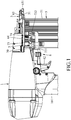
Figure 1 is a fragmentary side view illustrating a first embodiment of the nail gun according to the disclosure; -
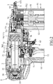
Figure 2 is a fragmentary sectional view illustrating the first embodiment; -
Figure 3 is another fragmentary sectional view illustrating the first embodiment; -
Figure 4 is a schematic sectional view illustrating a detection member of the first embodiment at a sealing position; and -
Figure 5 is another schematic sectional view illustrating the detection member at the sealing position. - Before the disclosure is described in greater detail, it should be noted that where considered appropriate, reference numerals or terminal portions of reference numerals have been repeated among the figures to indicate corresponding or analogous elements, which may optionally have similar characteristics.
- Referring to
Figures 1 and2 , the embodiment of the nail gun includes agun body 1, a power module 2, amuzzle module 3, amagazine module 5, afiring module 6 and adetection module 7. Thegun body 1 has ahandle 101. For convenience sake, in the following paragraphs, a distal portion of thehandle 101 is denoted as the lower portion of the nail gun, themuzzle module 3 is denoted as the front portion of the nail gun, and the rest can be deduced by analogy. - With particular reference to
Figure 2 , thegun body 1 further has arelease flow path 11 that is in communication with the outside of the nail gun and that is disposed adjacent to themagazine module 5, anintake channel 12 that is for introducing high-pressure air into the nail gun to form a first pressure, and a connecting flow path 13 (seeFigure 5 ) that is in communication with therelease flow path 11. Therelease flow path 11 has a small-diameter section 111, and a large-diameter section 112 that has a diameter larger than that of the small-diameter section 111. - The power module 2 is disposed in the
gun body 1, and is configured to perform a nail-driving operation in which the power module 2 outputs a striking force to strike a nail by receiving the first pressure. In one embodiment, the power module 2 uses high-pressure air as the power source, and includes acylinder 21 that is mounted in thegun body 1, apiston 22 that is movably disposed in thecylinder 21, adrive bit 23 that is co-movably mounted to thepiston 22, ahead valve 25 that removably blocks thecylinder 21, and arelease chamber 26 that is defined between thehead valve 25 and thegun body 1 and that is in communication with therelease flow path 11. Therelease chamber 26 receives the high-pressure introduced into the gun body to form a second pressure. - The
muzzle module 3 is mounted to a front portion of thegun body 1, and defines anail exit opening 31. - The
magazine module 5 includes amagazine housing 51 that is connected to themuzzle module 3 and that is adapted to receive a plurality of nails (not shown) therein, and anail feeder 52 that is movably disposed in themagazine housing 51 and that pushes the nails for moving the nails into themuzzle module 3 one at a time. Thenail feeder 52 has aprojection 521 that projects toward the outside of the magazine housing 51. - The
firing module 6 includes aplunger 61 that is movably mounted to thegun body 1 and that is operable for introducing the high-pressure air from theintake channel 12 into thecylinder 21, atrigger assembly 62 that is pivoted to thegun body 1 and that is operable to move theplunger 61, acontact arm 63 that is movably mounted to thegun body 1, and two contact-armresilient members 64. When theplunger 61 is not operated (seeFigure 2 ), thehead valve 25 is biased by the second pressure formed by the high-pressure air in therelease chamber 26 to block thecylinder 21 so that thecylinder 21 is prevented from receiving the first pressure by thehead valve 25. When theplunger 61 is operated to move to an activating position (seeFigure 3 ), the second pressure in therelease chamber 26 is released via therelease flow path 11, so that thehead valve 25 is biased by the first pressure to unblock thecylinder 21 and that the high-pressure air flows into thecylinder 21 to push thepiston 22 and thedrive bit 23 for firing the nails via the nail exit opening 31 (i.e., the nail-driving operation is activated). The abovementioned operation is the same as that of a conventional pneumatic nail gun. In one embodiment, the power module 2 may use gas or electric motor as the power source. The operation of a gas nail gun or an electric nail gun is well-known to one having ordinary skill in the art, and is not further described in the following paragraphs. - In some embodiment, the
contact arm 63 extends through themuzzle module 3, and has anabutment end 631 that is adjacent to thenail exit opening 31. The contact-armresilient members 64 are disposed between thecontact arm 63 and themuzzle module 3, and resiliently bias thecontact arm 63 to move rearwardly. Thecontact arm 63 is operable to move forwardly so that theabutment end 631 projects out of the nail exit opening 31. - The
detection module 7 is disposed in thegun body 1, and includes avalve rod 70, a valveresilient member 71, asealing ring 72, adetection member 73 and a detectionresilient member 74. - The
valve rod 70 is movably mounted in therelease flow path 11 of thegun body 1, and has arod portion 701 that is disposed in the small-diameter section 111 of therelease flow path 11, and ahead portion 702 that is disposed in the large-diameter section 112 of therelease flow path 11 and that is for removably blocking the small-diameter section 111. - The
sealing ring 72 is disposed in the large-diameter section 112 of therelease flow path 11, and is located between the small-diameter section 111 and thehead portion 702 of thevalve rod 70. - The valve
resilient member 71 has two opposite ends respectively abutting against thegun body 1 and thehead portion 702 of thevalve rod 70, and resiliently biases thehead portion 702 of thevalve rod 70 to be in air-tight contact with thesealing ring 72 for blocking the small-diameter section 111 of therelease flow path 11. - The
detection member 73 is pivoted to themagazine housing 51 and is operable to pivot between an unsealing position (seeFigures 2 and3 ) and a sealing position (seeFigures 4 and5 ), and has afirst arm portion 731, and asecond arm portion 732 that is opposite to thefirst arm portion 731 and that is located on the path of movement of theprojection 521 of thenail feeder 52. When thedetection member 73 is at the unsealing position, thefirst arm portion 731 pushes thevalve rod 70, so that thehead portion 702 of thevalve rod 70 is spaced apart from thesealing ring 72 and the small-diameter section 111 of therelease flow path 11 and that therelease flow path 11 is unsealed. When thedetection member 73 is at the sealing position, thesecond arm portion 732 is pushed by theprojection 521 of thenail feeder 52 and thefirst arm portion 731 is moved away from thevalve rod 70 so that thevalve rod 70 is biased by the valveresilient member 71 to move toward thedetection member 73 until thehead portion 702 of thevalve rod 70 is in air-tight contact with thesealing ring 72 to seal the small-diameter section 111 of therelease flow path 11. - The detection
resilient member 74 has two opposite ends respectively abutting against thedetection member 73 and themuzzle module 3, and resiliently biases thesecond arm portion 732 such that when theprojection 521 of thenail feeder 52 is spaced apart from thesecond arm portion 732, thefirst arm portion 731 pushes thevalve rod 70 against the biasing action of the valveresilient member 71 to maintain thevalve rod 70 to unseal the small-diameter section 111 of therelease flow path 11. When the number of the nails in themagazine housing 51 is less than a predetermined amount, theprojection 521 of thenail feeder 52 pushes thesecond arm portion 732 to move against the biasing action of the detectionresilient member 74 such that thefirst arm portion 731 is partially removed from the path of movement of thevalve rod 70 and that thevalve rod 70 is moved to seal the small-diameter section 111 by the valveresilient member 71. - Referring to
Figures 1 and2 , in a normal state, a distal portion of thetrigger assembly 62 is distal from thegun body 1, and thecontact arm 63 is maintained at a normal position by the contact-armresilient members 64 where theabutment end 631 of thecontact arm 63 is proximate to thenail exit opening 31. - Referring to
Figures 2 and3 , when thetrigger assembly 62 is depressed to pivot rearwardly, theplunger 61 is operated to move to the activating position (seeFigure 3 ), and the second pressure in therelease chamber 26 is released via therelease flow path 11, so that thehead valve 25 is biased by the first pressure to unblock thecylinder 21 and that the high-pressure air flows into thecylinder 21 to push thepiston 22 and thedrive bit 23 to fire the nail via thenail exit opening 31. - Referring to
Figures 4 and5 , in some embodiment, when thenail feeder 52 pushes the last nail in themagazine housing 51 into themuzzle module 3, theprojection 521 of thenail feeder 52 pushes thesecond arm portion 732 of thedetection member 73 to move against the biasing action of the detectionresilient member 74, such that thedetection member 73 is moved to the sealing position, in which thefirst arm portion 731 is partially removed from the path of movement of thevalve rod 70, and thevalve rod 70 is moved by the valveresilient member 71 to seal up therelease flow path 11. As such, even if theplunger 61 is moved to the activating position, the second pressure in therelease chamber 26 cannot be released via therelease flow path 11, so that thehead valve 25 would keep blocking thecylinder 21 and that the high-pressure air (i.e., the first pressure) would not be able to flow into thecylinder 21 for striking the nails (i.e., the nail-driving operation cannot be activated) . Therefore, dry-firing of the nail gun can be prevented. - It should be noted that, in this embodiment, the
magazine module 5 and thedetection module 7 are configured such that therelease flow path 11 is sealed so as to prevent dry-firing when there is no nail in themagazine housing 51. In a modification, themagazine module 5 and thedetection module 7 may be configured such that therelease flow path 11 is sealed when the number of thenails 7 in the magazine housing 41 is less than a predetermined amount. - To sum up, since the
first arm portion 731 of thedetection member 73 is not completely removed from the path of movement of thevalve rod 70 when thedetection member 73 is at the sealing position, thevalve rod 70 can be moved to unseal therelease flow path 11 by the movement of thedetection member 73 from the sealing position to the unsealing position without additional restoring structure. - In the description above, for the purposes of explanation, numerous specific details have been set forth in order to provide a thorough understanding of the embodiment. It will be apparent, however, to one skilled in the art, that one or more other embodiments may be practiced without some of these specific details. It should also be appreciated that reference throughout this specification to "one embodiment," "an embodiment," an embodiment with an indication of an ordinal number and so forth means that a particular feature, structure, or characteristic may be included in the practice of the disclosure. It should be further appreciated that in the description, various features are sometimes grouped together in a single embodiment, figure, or description thereof for the purpose of streamlining the disclosure and aiding in the understanding of various inventive aspects, and that one or more features or specific details from one embodiment may be practiced together with one or more features or specific details from another embodiment, where appropriate, in the practice of the disclosure.
Claims (11)
- A nail gun characterized by:a gun body (1);a power module (2) disposed in said gun body (1), said power module (2) being configured to perform a nail-driving operation in which said power module (2) outputs a striking force to strike a nail by receiving a first pressure, and prevented from receiving the first pressure when said power module (2) is subjected to a second pressure;a muzzle module (3) mounted to said gun body (1), and defining a nail exit opening (31);a magazine module (5) connected to said muzzle module (3) for pushing a plurality of nails to move into said muzzle module (3) one at a time;a firing module (6) mounted to said gun body (1), and operable to activate the nail-driving operation for firing the nails via said nail exit opening (31); anda detection module (7) including a valve rod (70) that is movably mounted to said gun body (1) for controlling the second pressure, and a detection member (73) that is pivoted to said magazine module (5) and that is operable to pivot between an unsealing position and a sealing position, said detection member (73) being moved to the sealing position when the number of the nails in said magazine module (5) is less than a predetermined amount;wherein, when said detection member (73) is at the unsealing position, said valve rod (70) is moved away from said detection member (73) to permit release of the second pressure; andwherein when said detection member (73) is at the sealing position, said valve rod (70) is moved toward said detection member (73) to prevent the second pressure from being released.
- The nail gun as claimed in claim 1, characterized in that said gun body (1) has a release flow path (11), said power module (2) including a cylinder (21) that is for receiving the first pressure, a head valve (25) that removably blocks said cylinder (21), and a release chamber (26) that is defined between said head valve (25) and said gun body (1) and that is in communication with said release flow path (11), said valve rod (70) being movably mounted in said release flow path (11).
- The nail gun as claimed in any one of claims 1 and 2, further characterized in that said gun body (1) further has an intake channel (12) that is for introducing high-pressure air to form a first pressure, said firing module (6) including a plunger (61) that is movably mounted to said gun body (1) and that is operable for introducing the first pressure into said cylinder (21), and a trigger assembly (62) that is pivoted to said gun body (1) and that is operable to drive said plunger (61).
- The nail gun as claimed in claim 2, further characterized in that said release flow path (11) has a small-diameter section (111), and a large-diameter section (112) that has a diameter larger than that of said small-diameter section (111), said valve rod (70) having a rod portion (701) that is disposed in said small-diameter section (111) of said release flow path (11), and a head portion (702) that is disposed in said large-diameter section (112) of said release flow path (11) and that is for removably blocking said small-diameter section (111).
- The nail gun as claimed in claim 4, further characterized in that said detection module (7) further includes a sealing ring (72) that is disposed in said large-diameter section (112) of said release flow path (11) and that is located between said small-diameter section (111) and said head portion (702) of said valve rod (70), said head portion (702) of said valve rod (70) being in air-tight contact with said sealing ring (72) when said detection member (73) is at the sealing position.
- The nail gun as claimed in any one of claims 1 to 5, characterized in that said magazine module (5) includes a magazine housing (51) that is adapted to receive the nails therein, and a nail feeder (52) that is movably disposed in said magazine housing (51) and that pushes the nails for moving the nails into said muzzle module (3) one at a time, said detection member (73) being pivoted to said magazine housing (51) and having a first arm portion (731) that is for pushing said valve rod (70), and a second arm portion (732) that is opposite to said first arm portion (731) and that is located on the path of movement of the said nail feeder (52), said nail feeder (52) driving said second arm portion (732) of said detection member (73) to move said detection member (73) to the sealing position when the number of the nails in said magazine housing (51) is less than a predetermined amount.
- The nail gun as claimed in claim 6, further characterized in that said nail feeder (52) has a projection (521) that projects toward the outside of said magazine housing (51), said projection (521) of said nail feeder (52) driving said second arm portion (732) of said detection member (73) to move said detection member (73) to the sealing position when the number of the nails in said magazine housing (51) is less than a predetermined amount.
- The nail gun as claimed in any one of claims 1 to 7, characterized in that said detection module (7) further includes a detection resilient member (74), said resilient member (74) having two opposite ends that respectively abut against said detection member (73) and said muzzle module (3), and resiliently biasing the second arm portion (732) for maintaining said detection member (73) at the unsealing position.
- The nail gun as claimed in any one of claims 1 to 8, characterized in that said detection module (7) further includes a valve resilient member (71) that has two opposite ends respectively abutting against said gun body (1) and said valve rod (70), and resiliently biases said valve rod (70) to prevent the second pressure from being released.
- The nail gun as claimed in any one of claims 1 to 9, characterized in that said firing module (6) includes a contact arm (63) that is movably mounted to said gun body (1), and a trigger assembly (62) that is pivoted to said gun body (1), said contact arm (63) having an abutment end (631) that is adjacent to said nail exit opening (31), said trigger assembly (62) operable to activate the nail-driving operation.
- The nail gun as claimed in claim 10, further characterized in that said contact arm (63) is operable to move forwardly so that said abutment end (631) projects out of said nail exit opening (31).
Applications Claiming Priority (1)
| Application Number | Priority Date | Filing Date | Title |
|---|---|---|---|
| TW107110876A TWI781157B (en) | 2018-03-29 | 2018-03-29 | Nailless and unfireable nail gun |
Publications (2)
| Publication Number | Publication Date |
|---|---|
| EP3546128A1 true EP3546128A1 (en) | 2019-10-02 |
| EP3546128B1 EP3546128B1 (en) | 2022-08-24 |
Family
ID=65991662
Family Applications (1)
| Application Number | Title | Priority Date | Filing Date |
|---|---|---|---|
| EP19165297.3A Active EP3546128B1 (en) | 2018-03-29 | 2019-03-26 | Nail gun |
Country Status (3)
| Country | Link |
|---|---|
| US (1) | US11154971B2 (en) |
| EP (1) | EP3546128B1 (en) |
| TW (1) | TWI781157B (en) |
Cited By (2)
| Publication number | Priority date | Publication date | Assignee | Title |
|---|---|---|---|---|
| CN109159080A (en) * | 2018-09-29 | 2019-01-08 | 广州市美术有限公司 | A kind of nailing gun with safety device |
| CN114211459A (en) * | 2022-01-11 | 2022-03-22 | 瑞安市朗辰气动工具有限公司 | Nailing gun with reserved nail rod height |
Families Citing this family (2)
| Publication number | Priority date | Publication date | Assignee | Title |
|---|---|---|---|---|
| EP4126460A4 (en) | 2020-03-27 | 2023-12-06 | Milwaukee Electric Tool Corporation | Powered fastener driver |
| EP4126462A1 (en) | 2020-03-31 | 2023-02-08 | Milwaukee Electric Tool Corporation | Powered fastener driver |
Citations (4)
| Publication number | Priority date | Publication date | Assignee | Title |
|---|---|---|---|---|
| CA879401A (en) * | 1971-08-31 | Fastener Corporation | Fastener driving tool | |
| DE2247072A1 (en) * | 1972-09-26 | 1974-04-25 | Dieter Haubold Ind Nagelgeraet | RELEASE LOCK TO PREVENT EMPTY STOCKING IN THE EVENT OF EMPTY MAGAZINES FOR A COMPRESSED AIR-OPERATED HAND DEVICE FOR DRIVING FASTENERS |
| TWI349600B (en) | 2007-10-24 | 2011-10-01 | Basso Ind Corp | |
| EP2441552A2 (en) * | 2010-10-12 | 2012-04-18 | Stanley Fastening Systems L.P. | Dry fire lockout with bypass for fastener driving device |
Family Cites Families (19)
| Publication number | Priority date | Publication date | Assignee | Title |
|---|---|---|---|---|
| GB879401A (en) | 1958-07-23 | 1961-10-11 | Pye Ltd | Circuit arrangement for reducing the d.c. level of a signal |
| US3563438A (en) * | 1968-12-05 | 1971-02-16 | Fastener Corp | Fastener driving tool |
| US3572572A (en) * | 1969-07-22 | 1971-03-30 | Textron Inc | Fluid pressure operated fastener driving device |
| US3905535A (en) * | 1973-09-13 | 1975-09-16 | Duo Fast Corp | Fastener driving tool |
| JP5034177B2 (en) * | 2005-05-25 | 2012-09-26 | マックス株式会社 | Driving tool safety device |
| JP4992199B2 (en) * | 2005-05-25 | 2012-08-08 | マックス株式会社 | Driving tool contact mechanism |
| DE102005000107B4 (en) * | 2005-08-25 | 2014-03-13 | Hilti Aktiengesellschaft | Pneumatically operated setting tool |
| US7677426B2 (en) * | 2005-09-19 | 2010-03-16 | Stanley Fastening Systems, L.P. | Fastener driving device |
| TWM290089U (en) * | 2005-11-10 | 2006-05-01 | Nailermate Entpr Corp | Nail-free trigger braking structure of nailing gun |
| TW200824854A (en) * | 2006-12-12 | 2008-06-16 | De Poan Pneumatic Corp | Empty nail brake/trigger apparatus of nail gun |
| TW200914214A (en) * | 2007-09-21 | 2009-04-01 | De Poan Pneumatic Corp | Firing braking apparatus of empty cartridge for nail gun |
| US20090302087A1 (en) * | 2008-06-06 | 2009-12-10 | Chia-Sheng Liang | Adjusting Mechanism for Control Valve of Nail Guns |
| US8800835B2 (en) * | 2008-07-17 | 2014-08-12 | Stanley Fastening Systems, Lp | Fastener driving device with mode selector and trigger interlock |
| TW201117930A (en) * | 2009-11-19 | 2011-06-01 | De Poan Pneumatic Corp | Driving device for resetting a nail hitting bar the a pneumatic nail gun |
| US8636185B2 (en) * | 2010-11-15 | 2014-01-28 | Illinois Tool Works Inc. | Fastener advance delay for fastener driving tool |
| TWM511932U (en) * | 2015-06-18 | 2015-11-11 | Basso Ind Corp | Firing-free nail gun without nails |
| TWI767933B (en) * | 2017-08-25 | 2022-06-21 | 鑽全實業股份有限公司 | Nail gun and its actuating device |
| TWI746637B (en) * | 2017-09-14 | 2021-11-21 | 鑽全實業股份有限公司 | Nail gun and its driving device |
| JP6950423B2 (en) * | 2017-09-29 | 2021-10-13 | マックス株式会社 | Driving tool |
-
2018
- 2018-03-29 TW TW107110876A patent/TWI781157B/en active
-
2019
- 2019-03-20 US US16/358,947 patent/US11154971B2/en active Active
- 2019-03-26 EP EP19165297.3A patent/EP3546128B1/en active Active
Patent Citations (4)
| Publication number | Priority date | Publication date | Assignee | Title |
|---|---|---|---|---|
| CA879401A (en) * | 1971-08-31 | Fastener Corporation | Fastener driving tool | |
| DE2247072A1 (en) * | 1972-09-26 | 1974-04-25 | Dieter Haubold Ind Nagelgeraet | RELEASE LOCK TO PREVENT EMPTY STOCKING IN THE EVENT OF EMPTY MAGAZINES FOR A COMPRESSED AIR-OPERATED HAND DEVICE FOR DRIVING FASTENERS |
| TWI349600B (en) | 2007-10-24 | 2011-10-01 | Basso Ind Corp | |
| EP2441552A2 (en) * | 2010-10-12 | 2012-04-18 | Stanley Fastening Systems L.P. | Dry fire lockout with bypass for fastener driving device |
Cited By (2)
| Publication number | Priority date | Publication date | Assignee | Title |
|---|---|---|---|---|
| CN109159080A (en) * | 2018-09-29 | 2019-01-08 | 广州市美术有限公司 | A kind of nailing gun with safety device |
| CN114211459A (en) * | 2022-01-11 | 2022-03-22 | 瑞安市朗辰气动工具有限公司 | Nailing gun with reserved nail rod height |
Also Published As
| Publication number | Publication date |
|---|---|
| US11154971B2 (en) | 2021-10-26 |
| TWI781157B (en) | 2022-10-21 |
| EP3546128B1 (en) | 2022-08-24 |
| US20190299381A1 (en) | 2019-10-03 |
| TW201941882A (en) | 2019-11-01 |
Similar Documents
| Publication | Publication Date | Title |
|---|---|---|
| US11154971B2 (en) | Nail gun | |
| WO2016002540A1 (en) | Driving machine | |
| US10814466B2 (en) | Nail gun and operation device thereof | |
| CN111372730A (en) | Pneumatic nail gun with safety valve assembly | |
| US20060169265A1 (en) | Shooting structure of a paint bullet gun | |
| TWI579116B (en) | Pneumatic nailer with sleeve actuated piston return | |
| US7793644B2 (en) | Firing mechanism for paintball gun | |
| JP2014233770A (en) | Driving machine | |
| AU2013217000B2 (en) | Sleeve for a pneumatic fastener-driving tool | |
| TW201912335A (en) | Nail gun and its actuating device | |
| US10960524B2 (en) | Nail gun and switchable trigger device thereof | |
| JP7108369B2 (en) | Air nailer with single shot and contact trigger | |
| US5865360A (en) | Fastener driving device with trigger valve | |
| US20230083323A1 (en) | Pneumatic Actuation Valve Assembly | |
| US20070163563A1 (en) | Gas gun having spring loading bolt | |
| CN111225769A (en) | Pneumatic nail gun with safety adjusting element | |
| CA2715457A1 (en) | Pneumatic impact tool | |
| JP3041544B2 (en) | Bullet launcher for toy guns | |
| US20060157529A1 (en) | Device for providing sufficient time to allow piston of pneumatic nailers to move backward | |
| CN216152266U (en) | Pneumatic nail gun using forward switch device | |
| US20070215669A1 (en) | Device for providing sufficient time to allow piston of pneumatic nailers to move backward | |
| RU2800110C2 (en) | Pneumatic nail gun with safety mechanism | |
| CN106475967B (en) | Driving tool | |
| EP2141440B1 (en) | Bullet-loading assembly for a toy gun | |
| TW202128368A (en) | Time-delayed detent device that is mountable on a pneumatic nailing gun and comprises a detent unit and a valve unit for introducing or discharging a second airflow |
Legal Events
| Date | Code | Title | Description |
|---|---|---|---|
| PUAI | Public reference made under article 153(3) epc to a published international application that has entered the european phase |
Free format text: ORIGINAL CODE: 0009012 |
|
| STAA | Information on the status of an ep patent application or granted ep patent |
Free format text: STATUS: REQUEST FOR EXAMINATION WAS MADE |
|
| 17P | Request for examination filed |
Effective date: 20190326 |
|
| AK | Designated contracting states |
Kind code of ref document: A1 Designated state(s): AL AT BE BG CH CY CZ DE DK EE ES FI FR GB GR HR HU IE IS IT LI LT LU LV MC MK MT NL NO PL PT RO RS SE SI SK SM TR |
|
| AX | Request for extension of the european patent |
Extension state: BA ME |
|
| GRAP | Despatch of communication of intention to grant a patent |
Free format text: ORIGINAL CODE: EPIDOSNIGR1 |
|
| STAA | Information on the status of an ep patent application or granted ep patent |
Free format text: STATUS: GRANT OF PATENT IS INTENDED |
|
| INTG | Intention to grant announced |
Effective date: 20220311 |
|
| GRAS | Grant fee paid |
Free format text: ORIGINAL CODE: EPIDOSNIGR3 |
|
| GRAA | (expected) grant |
Free format text: ORIGINAL CODE: 0009210 |
|
| STAA | Information on the status of an ep patent application or granted ep patent |
Free format text: STATUS: THE PATENT HAS BEEN GRANTED |
|
| RAP3 | Party data changed (applicant data changed or rights of an application transferred) |
Owner name: BASSO INDUSTRY CORP. |
|
| AK | Designated contracting states |
Kind code of ref document: B1 Designated state(s): AL AT BE BG CH CY CZ DE DK EE ES FI FR GB GR HR HU IE IS IT LI LT LU LV MC MK MT NL NO PL PT RO RS SE SI SK SM TR |
|
| REG | Reference to a national code |
Ref country code: CH Ref legal event code: EP |
|
| REG | Reference to a national code |
Ref country code: IE Ref legal event code: FG4D |
|
| REG | Reference to a national code |
Ref country code: AT Ref legal event code: REF Ref document number: 1513326 Country of ref document: AT Kind code of ref document: T Effective date: 20220915 Ref country code: DE Ref legal event code: R096 Ref document number: 602019018539 Country of ref document: DE |
|
| REG | Reference to a national code |
Ref country code: SE Ref legal event code: TRGR |
|
| REG | Reference to a national code |
Ref country code: LT Ref legal event code: MG9D |
|
| REG | Reference to a national code |
Ref country code: NO Ref legal event code: T2 Effective date: 20220824 |
|
| REG | Reference to a national code |
Ref country code: NL Ref legal event code: MP Effective date: 20220824 |
|
| PG25 | Lapsed in a contracting state [announced via postgrant information from national office to epo] |
Ref country code: RS Free format text: LAPSE BECAUSE OF FAILURE TO SUBMIT A TRANSLATION OF THE DESCRIPTION OR TO PAY THE FEE WITHIN THE PRESCRIBED TIME-LIMIT Effective date: 20220824 Ref country code: PT Free format text: LAPSE BECAUSE OF FAILURE TO SUBMIT A TRANSLATION OF THE DESCRIPTION OR TO PAY THE FEE WITHIN THE PRESCRIBED TIME-LIMIT Effective date: 20221226 Ref country code: NL Free format text: LAPSE BECAUSE OF FAILURE TO SUBMIT A TRANSLATION OF THE DESCRIPTION OR TO PAY THE FEE WITHIN THE PRESCRIBED TIME-LIMIT Effective date: 20220824 Ref country code: LV Free format text: LAPSE BECAUSE OF FAILURE TO SUBMIT A TRANSLATION OF THE DESCRIPTION OR TO PAY THE FEE WITHIN THE PRESCRIBED TIME-LIMIT Effective date: 20220824 Ref country code: LT Free format text: LAPSE BECAUSE OF FAILURE TO SUBMIT A TRANSLATION OF THE DESCRIPTION OR TO PAY THE FEE WITHIN THE PRESCRIBED TIME-LIMIT Effective date: 20220824 Ref country code: FI Free format text: LAPSE BECAUSE OF FAILURE TO SUBMIT A TRANSLATION OF THE DESCRIPTION OR TO PAY THE FEE WITHIN THE PRESCRIBED TIME-LIMIT Effective date: 20220824 |
|
| REG | Reference to a national code |
Ref country code: AT Ref legal event code: MK05 Ref document number: 1513326 Country of ref document: AT Kind code of ref document: T Effective date: 20220824 |
|
| PG25 | Lapsed in a contracting state [announced via postgrant information from national office to epo] |
Ref country code: PL Free format text: LAPSE BECAUSE OF FAILURE TO SUBMIT A TRANSLATION OF THE DESCRIPTION OR TO PAY THE FEE WITHIN THE PRESCRIBED TIME-LIMIT Effective date: 20220824 Ref country code: IS Free format text: LAPSE BECAUSE OF FAILURE TO SUBMIT A TRANSLATION OF THE DESCRIPTION OR TO PAY THE FEE WITHIN THE PRESCRIBED TIME-LIMIT Effective date: 20221224 Ref country code: HR Free format text: LAPSE BECAUSE OF FAILURE TO SUBMIT A TRANSLATION OF THE DESCRIPTION OR TO PAY THE FEE WITHIN THE PRESCRIBED TIME-LIMIT Effective date: 20220824 Ref country code: GR Free format text: LAPSE BECAUSE OF FAILURE TO SUBMIT A TRANSLATION OF THE DESCRIPTION OR TO PAY THE FEE WITHIN THE PRESCRIBED TIME-LIMIT Effective date: 20221125 |
|
| PG25 | Lapsed in a contracting state [announced via postgrant information from national office to epo] |
Ref country code: SM Free format text: LAPSE BECAUSE OF FAILURE TO SUBMIT A TRANSLATION OF THE DESCRIPTION OR TO PAY THE FEE WITHIN THE PRESCRIBED TIME-LIMIT Effective date: 20220824 Ref country code: RO Free format text: LAPSE BECAUSE OF FAILURE TO SUBMIT A TRANSLATION OF THE DESCRIPTION OR TO PAY THE FEE WITHIN THE PRESCRIBED TIME-LIMIT Effective date: 20220824 Ref country code: ES Free format text: LAPSE BECAUSE OF FAILURE TO SUBMIT A TRANSLATION OF THE DESCRIPTION OR TO PAY THE FEE WITHIN THE PRESCRIBED TIME-LIMIT Effective date: 20220824 Ref country code: DK Free format text: LAPSE BECAUSE OF FAILURE TO SUBMIT A TRANSLATION OF THE DESCRIPTION OR TO PAY THE FEE WITHIN THE PRESCRIBED TIME-LIMIT Effective date: 20220824 Ref country code: CZ Free format text: LAPSE BECAUSE OF FAILURE TO SUBMIT A TRANSLATION OF THE DESCRIPTION OR TO PAY THE FEE WITHIN THE PRESCRIBED TIME-LIMIT Effective date: 20220824 Ref country code: AT Free format text: LAPSE BECAUSE OF FAILURE TO SUBMIT A TRANSLATION OF THE DESCRIPTION OR TO PAY THE FEE WITHIN THE PRESCRIBED TIME-LIMIT Effective date: 20220824 |
|
| PGFP | Annual fee paid to national office [announced via postgrant information from national office to epo] |
Ref country code: NO Payment date: 20230215 Year of fee payment: 5 |
|
| REG | Reference to a national code |
Ref country code: DE Ref legal event code: R097 Ref document number: 602019018539 Country of ref document: DE |
|
| PG25 | Lapsed in a contracting state [announced via postgrant information from national office to epo] |
Ref country code: SK Free format text: LAPSE BECAUSE OF FAILURE TO SUBMIT A TRANSLATION OF THE DESCRIPTION OR TO PAY THE FEE WITHIN THE PRESCRIBED TIME-LIMIT Effective date: 20220824 Ref country code: EE Free format text: LAPSE BECAUSE OF FAILURE TO SUBMIT A TRANSLATION OF THE DESCRIPTION OR TO PAY THE FEE WITHIN THE PRESCRIBED TIME-LIMIT Effective date: 20220824 |
|
| PGFP | Annual fee paid to national office [announced via postgrant information from national office to epo] |
Ref country code: SE Payment date: 20230210 Year of fee payment: 5 Ref country code: DE Payment date: 20230210 Year of fee payment: 5 |
|
| PG25 | Lapsed in a contracting state [announced via postgrant information from national office to epo] |
Ref country code: AL Free format text: LAPSE BECAUSE OF FAILURE TO SUBMIT A TRANSLATION OF THE DESCRIPTION OR TO PAY THE FEE WITHIN THE PRESCRIBED TIME-LIMIT Effective date: 20220824 |
|
| PLBE | No opposition filed within time limit |
Free format text: ORIGINAL CODE: 0009261 |
|
| STAA | Information on the status of an ep patent application or granted ep patent |
Free format text: STATUS: NO OPPOSITION FILED WITHIN TIME LIMIT |
|
| 26N | No opposition filed |
Effective date: 20230525 |
|
| PG25 | Lapsed in a contracting state [announced via postgrant information from national office to epo] |
Ref country code: SI Free format text: LAPSE BECAUSE OF FAILURE TO SUBMIT A TRANSLATION OF THE DESCRIPTION OR TO PAY THE FEE WITHIN THE PRESCRIBED TIME-LIMIT Effective date: 20220824 |
|
| PG25 | Lapsed in a contracting state [announced via postgrant information from national office to epo] |
Ref country code: MC Free format text: LAPSE BECAUSE OF FAILURE TO SUBMIT A TRANSLATION OF THE DESCRIPTION OR TO PAY THE FEE WITHIN THE PRESCRIBED TIME-LIMIT Effective date: 20220824 |
|
| REG | Reference to a national code |
Ref country code: CH Ref legal event code: PL |
|
| GBPC | Gb: european patent ceased through non-payment of renewal fee |
Effective date: 20230326 |
|
| REG | Reference to a national code |
Ref country code: BE Ref legal event code: MM Effective date: 20230331 |
|
| PG25 | Lapsed in a contracting state [announced via postgrant information from national office to epo] |
Ref country code: LU Free format text: LAPSE BECAUSE OF NON-PAYMENT OF DUE FEES Effective date: 20230326 |
|
| REG | Reference to a national code |
Ref country code: IE Ref legal event code: MM4A |
|
| PG25 | Lapsed in a contracting state [announced via postgrant information from national office to epo] |
Ref country code: GB Free format text: LAPSE BECAUSE OF NON-PAYMENT OF DUE FEES Effective date: 20230326 |
|
| PG25 | Lapsed in a contracting state [announced via postgrant information from national office to epo] |
Ref country code: LI Free format text: LAPSE BECAUSE OF NON-PAYMENT OF DUE FEES Effective date: 20230331 Ref country code: IE Free format text: LAPSE BECAUSE OF NON-PAYMENT OF DUE FEES Effective date: 20230326 Ref country code: GB Free format text: LAPSE BECAUSE OF NON-PAYMENT OF DUE FEES Effective date: 20230326 Ref country code: FR Free format text: LAPSE BECAUSE OF NON-PAYMENT OF DUE FEES Effective date: 20230331 Ref country code: CH Free format text: LAPSE BECAUSE OF NON-PAYMENT OF DUE FEES Effective date: 20230331 |
|
| PG25 | Lapsed in a contracting state [announced via postgrant information from national office to epo] |
Ref country code: BE Free format text: LAPSE BECAUSE OF NON-PAYMENT OF DUE FEES Effective date: 20230331 |