EP3545931A1 - Trolley brake assembly - Google Patents
Trolley brake assembly Download PDFInfo
- Publication number
- EP3545931A1 EP3545931A1 EP19162216.6A EP19162216A EP3545931A1 EP 3545931 A1 EP3545931 A1 EP 3545931A1 EP 19162216 A EP19162216 A EP 19162216A EP 3545931 A1 EP3545931 A1 EP 3545931A1
- Authority
- EP
- European Patent Office
- Prior art keywords
- trolley
- brake pad
- brake
- release mechanism
- floor surface
- Prior art date
- Legal status (The legal status is an assumption and is not a legal conclusion. Google has not performed a legal analysis and makes no representation as to the accuracy of the status listed.)
- Withdrawn
Links
Images

Classifications
-
- B—PERFORMING OPERATIONS; TRANSPORTING
- B62—LAND VEHICLES FOR TRAVELLING OTHERWISE THAN ON RAILS
- B62B—HAND-PROPELLED VEHICLES, e.g. HAND CARTS OR PERAMBULATORS; SLEDGES
- B62B5/00—Accessories or details specially adapted for hand carts
- B62B5/04—Braking mechanisms; Locking devices against movement
- B62B5/049—Braking mechanisms; Locking devices against movement locking against movement by contacting the floor or a wall
-
- A—HUMAN NECESSITIES
- A61—MEDICAL OR VETERINARY SCIENCE; HYGIENE
- A61G—TRANSPORT, PERSONAL CONVEYANCES, OR ACCOMMODATION SPECIALLY ADAPTED FOR PATIENTS OR DISABLED PERSONS; OPERATING TABLES OR CHAIRS; CHAIRS FOR DENTISTRY; FUNERAL DEVICES
- A61G12/00—Accommodation for nursing, e.g. in hospitals, not covered by groups A61G1/00 - A61G11/00, e.g. trolleys for transport of medicaments or food; Prescription lists
- A61G12/001—Trolleys for transport of medicaments, food, linen, nursing supplies
-
- A—HUMAN NECESSITIES
- A61—MEDICAL OR VETERINARY SCIENCE; HYGIENE
- A61G—TRANSPORT, PERSONAL CONVEYANCES, OR ACCOMMODATION SPECIALLY ADAPTED FOR PATIENTS OR DISABLED PERSONS; OPERATING TABLES OR CHAIRS; CHAIRS FOR DENTISTRY; FUNERAL DEVICES
- A61G5/00—Chairs or personal conveyances specially adapted for patients or disabled persons, e.g. wheelchairs
- A61G5/10—Parts, details or accessories
- A61G5/1005—Wheelchairs having brakes
- A61G5/1029—Wheelchairs having brakes engaging a surface, e.g. floor or wall
-
- B—PERFORMING OPERATIONS; TRANSPORTING
- B60—VEHICLES IN GENERAL
- B60T—VEHICLE BRAKE CONTROL SYSTEMS OR PARTS THEREOF; BRAKE CONTROL SYSTEMS OR PARTS THEREOF, IN GENERAL; ARRANGEMENT OF BRAKING ELEMENTS ON VEHICLES IN GENERAL; PORTABLE DEVICES FOR PREVENTING UNWANTED MOVEMENT OF VEHICLES; VEHICLE MODIFICATIONS TO FACILITATE COOLING OF BRAKES
- B60T1/00—Arrangements of braking elements, i.e. of those parts where braking effect occurs specially for vehicles
- B60T1/12—Arrangements of braking elements, i.e. of those parts where braking effect occurs specially for vehicles acting otherwise than by retarding wheels, e.g. jet action
- B60T1/14—Arrangements of braking elements, i.e. of those parts where braking effect occurs specially for vehicles acting otherwise than by retarding wheels, e.g. jet action directly on road
-
- B—PERFORMING OPERATIONS; TRANSPORTING
- B62—LAND VEHICLES FOR TRAVELLING OTHERWISE THAN ON RAILS
- B62B—HAND-PROPELLED VEHICLES, e.g. HAND CARTS OR PERAMBULATORS; SLEDGES
- B62B1/00—Hand carts having only one axis carrying one or more transport wheels; Equipment therefor
-
- B—PERFORMING OPERATIONS; TRANSPORTING
- B62—LAND VEHICLES FOR TRAVELLING OTHERWISE THAN ON RAILS
- B62B—HAND-PROPELLED VEHICLES, e.g. HAND CARTS OR PERAMBULATORS; SLEDGES
- B62B3/00—Hand carts having more than one axis carrying transport wheels; Steering devices therefor; Equipment therefor
-
- B—PERFORMING OPERATIONS; TRANSPORTING
- B62—LAND VEHICLES FOR TRAVELLING OTHERWISE THAN ON RAILS
- B62B—HAND-PROPELLED VEHICLES, e.g. HAND CARTS OR PERAMBULATORS; SLEDGES
- B62B5/00—Accessories or details specially adapted for hand carts
- B62B5/04—Braking mechanisms; Locking devices against movement
- B62B5/0438—Braking mechanisms; Locking devices against movement hand operated
- B62B5/0442—Braking mechanisms; Locking devices against movement hand operated using a handle bar alone
-
- B—PERFORMING OPERATIONS; TRANSPORTING
- B62—LAND VEHICLES FOR TRAVELLING OTHERWISE THAN ON RAILS
- B62B—HAND-PROPELLED VEHICLES, e.g. HAND CARTS OR PERAMBULATORS; SLEDGES
- B62B5/00—Accessories or details specially adapted for hand carts
- B62B5/04—Braking mechanisms; Locking devices against movement
- B62B5/0438—Braking mechanisms; Locking devices against movement hand operated
- B62B5/0447—Braking mechanisms; Locking devices against movement hand operated using elements cooperating with a handle bar
-
- F—MECHANICAL ENGINEERING; LIGHTING; HEATING; WEAPONS; BLASTING
- F16—ENGINEERING ELEMENTS AND UNITS; GENERAL MEASURES FOR PRODUCING AND MAINTAINING EFFECTIVE FUNCTIONING OF MACHINES OR INSTALLATIONS; THERMAL INSULATION IN GENERAL
- F16D—COUPLINGS FOR TRANSMITTING ROTATION; CLUTCHES; BRAKES
- F16D65/00—Parts or details
- F16D65/02—Braking members; Mounting thereof
- F16D65/04—Bands, shoes or pads; Pivots or supporting members therefor
-
- F—MECHANICAL ENGINEERING; LIGHTING; HEATING; WEAPONS; BLASTING
- F16—ENGINEERING ELEMENTS AND UNITS; GENERAL MEASURES FOR PRODUCING AND MAINTAINING EFFECTIVE FUNCTIONING OF MACHINES OR INSTALLATIONS; THERMAL INSULATION IN GENERAL
- F16M—FRAMES, CASINGS OR BEDS OF ENGINES, MACHINES OR APPARATUS, NOT SPECIFIC TO ENGINES, MACHINES OR APPARATUS PROVIDED FOR ELSEWHERE; STANDS; SUPPORTS
- F16M11/00—Stands or trestles as supports for apparatus or articles placed thereon Stands for scientific apparatus such as gravitational force meters
- F16M11/42—Stands or trestles as supports for apparatus or articles placed thereon Stands for scientific apparatus such as gravitational force meters with arrangement for propelling the support stands on wheels
-
- B—PERFORMING OPERATIONS; TRANSPORTING
- B62—LAND VEHICLES FOR TRAVELLING OTHERWISE THAN ON RAILS
- B62B—HAND-PROPELLED VEHICLES, e.g. HAND CARTS OR PERAMBULATORS; SLEDGES
- B62B2301/00—Wheel arrangements; Steering; Stability; Wheel suspension
- B62B2301/04—Wheel arrangements; Steering; Stability; Wheel suspension comprising a wheel pivotable about a substantially vertical axis, e.g. swivelling castors
- B62B2301/044—Wheel arrangements; Steering; Stability; Wheel suspension comprising a wheel pivotable about a substantially vertical axis, e.g. swivelling castors arranged remote from the longitudinal centreline of the hand propelled vehicle
-
- F—MECHANICAL ENGINEERING; LIGHTING; HEATING; WEAPONS; BLASTING
- F16—ENGINEERING ELEMENTS AND UNITS; GENERAL MEASURES FOR PRODUCING AND MAINTAINING EFFECTIVE FUNCTIONING OF MACHINES OR INSTALLATIONS; THERMAL INSULATION IN GENERAL
- F16M—FRAMES, CASINGS OR BEDS OF ENGINES, MACHINES OR APPARATUS, NOT SPECIFIC TO ENGINES, MACHINES OR APPARATUS PROVIDED FOR ELSEWHERE; STANDS; SUPPORTS
- F16M2200/00—Details of stands or supports
- F16M2200/08—Foot or support base
Definitions
- the present invention relates to a brake device for a wheeled trolley. It is particularly suitable for use with a trolley carrying medical equipment, although it is also applicable to other types of trolley.
- trolleys with patient monitoring or diagnostic equipment
- trolleys with apparatus for intravenous delivery of medicaments and so on typically have a frame mounted on a number of castor wheels, so the direction of trolley movement can be altered easily.
- Each castor wheel is provided with a brake which may be foot operated by a user.
- engaging and disengaging the brake on each castor wheel is cumbersome and time consuming and in practice, users frequently will not bother to operate the brakes for each, or indeed any, wheel so that the trolley is at least partially mobile even when the equipment is in use. Therefore, there is a risk the trolley may move accidentally, causing injury to a patient or the user or damage to the equipment.
- the present invention provides a trolley having a base mounted on a plurality of wheels, and a brake comprising at least one deformable brake pad located beneath the base of the trolley and a release mechanism operable to move the brake pad between a raised position in which the brake pad is spaced above a floor surface on which the wheels of the trolley rest and a lowered position in which the brake pad is pressed against the floor surface under the weight of the brake device to exert a frictional force inhibiting movement of the trolley across the floor surface.
- the release mechanism comprises an elongate extension member extending upwardly from the backing plate and a handle operable by a user to raise and lower the elongate extension member.
- the release mechanism preferably further comprises guide means with end stops to define the raised and lowered positions of the brake device and to guide movement of the handle between the end stops.
- the extension member is slideably received within a hollow part of the trolley and the guide means comprises a slot formed in the hollow part through which the handle extends.
- Biasing means may be provided operable to press the brake pad against the floor surface in the lowered position.
- the biasing means may comprise spring means located between a part of the trolley and the brake and configured to bias the brake pad downwardly when it is in the lowered position, or a weight mounted on the release mechanism.
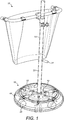
- FIG. 1 illustrates a typical trolley 10 for medical equipment in which a brake device 12 in accordance with the present invention is incorporated.
- the trolley 10 in this example has a central upright pole 14, to which medical equipment may be attached, and a base 16 comprising a number of radiating feet 18 each attached to a swivel castor wheel assembly 20.
- the base 16 is covered by a protective skirt 44 which is described further below.
- the skirt 44 is shown transparent in order to illustrate the components below.
- the brake pad 22 is a body of deformable or compressible material with non-slip or high friction properties so that it will resist slipping once it is pressed into contact with another surface.
- the brake pad 22 comprises a circular moulded mat with a plurality of projections or fingers 28.
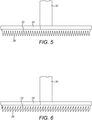
- the mat is attached to the underside of a circular backing plate 24 so that the fingers 28 extend downwardly as shown in Figure 5 .
- the mat is formed of a flexible elastomeric material such as rubber or silicone.
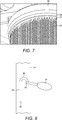
- the fingers 28 may be conical, or pyramid-shaped with a number of flat faces as shown in Figure 7 . However, the shape and dimensions of the fingers 28 may be altered as desired to provide the appropriate flexibility and to give the required braking effect when contacting the floor surface.
- the brake pad 22 may be formed of any suitable deformable or compressible material, such as a foam or sponge.
- the release mechanism 26 comprises the backing plate 24 and an elongate extension member 30 which extends upwardly from the backing plate 24.
- the extension member 30 is preferably slideably received within the central pole 14 of the trolley 10 and can be moved up and down within the pole 14 in order to raise and lower the brake pad 22.
- the release mechanism 26 may further comprise a handle 34 projecting laterally from an upper region of the extension member 30 through a slot 36 in the pole 14, as seen in Figures 1 and 8 .
- the slot 36 is shaped to hold the handle 34 in an upper position in which the brake pad 22 is raised above the floor, and to allow it to be moved to a lower position in which the brake pad 22 is pressed against the floor.
- the slot 36 may be in the form of an inverted bayonet fitting or arch shape with one leg of the arch extending further down the pole 14 than the other.
- the release mechanism 26 is configured and dimensioned such that in the lowered position, the brake pad 22 is pushed down against the floor surface so that the brake pad 22 will deform or compress and the projecting fingers 28 will bend in order to increase the contact area with the floor in order to exert a significant braking force on the trolley 10.
- An additional biasing means 32 may be provided to increase the downward force on the brake pad 22.
- spring means may be provided which pushes downwardly on the extension member 30.
- Such spring means may be located within the pole 14 between a stop and the top of the extension member 30.
- spring means may be provided between the base 16 of the trolley 10 and the backing plate 24. In the raised position, the spring means is held in a compressed state and cannot extend because the handle 34 is retained in the upper end 38 of the slot 36.
- the spring means is able to extend and exert a downward force on the brake pad 22.
- the weight of the extension member 30 and the backing plate 24 may be sufficient to press the brake pad 22 against the floor, or additional weight may be added.
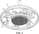
- a heavy disc 46 may be provided on the top of the backing plate 24 as shown in Figure 2 . The weight of the disc 46 will depend on the material used for the brake pad 22 and the configuration of the fingers 28 and will be chosen to ensure an optimal amount of friction with the floor surface.
- the release mechanism should be a simple robust mechanism, which is easily accessible for the user without the need to bend down, and straightforward to operate, to encourage a user to make use of the brake device. Locating the release mechanism 26 within part of the trolley frame is not essential but is advantageous because it minimises the risk of trapping a user's fingers or other items between relatively moving parts of the device. Positioning the brake pad 22 beneath the trolley base and not projecting out beyond the wheels 20 ensures the brake device 12 does not form a trip hazard.
- a protective skirt 44 may be fitted on the trolley 10 over the base 16 as shown in Figures1-4 . This prevents a user tripping over the radiating feet 18 and also prevents cables or other items becoming tangled with the feet 18, the wheels 20 or the brake device 12.
- the skirt 44 may be a moulded plastic shell which fits over the pole 14 and the base 16 and is dimensioned to sit a few millimetres above the floor surface so that it will not interfere with the rolling action of the trolley 10.
- the brake device 12 of the present invention has been described with a single brake pad 22 fitted to a trolley with a single central upright pole 14.
- the brake device 12 can be adapted for use with other types of trolley.
- more than one brake pad may be provided beneath the trolley base.
- the release mechanism may be adapted to fit the trolley configuration as required. For example, it may be located in one or more of the uprights, with a suitable linkage to connect the release mechanism to the or each brake pad. It is preferable if a single release mechanism operates all the brake pads, to retain the simplicity of use and encourage a user to apply the brake when required.
- the present invention provides a simple but effective braking device for a trolley, which can be operated by the user in one movement and without bending down, to encourage the user to make use of the brake device when required.
Abstract
Description
- The present invention relates to a brake device for a wheeled trolley. It is particularly suitable for use with a trolley carrying medical equipment, although it is also applicable to other types of trolley.
- Hospitals and medicals facilities frequently use equipment mounted on trolleys so that it can be easily moved to different locations as required. Examples include trolleys with patient monitoring or diagnostic equipment, trolleys with apparatus for intravenous delivery of medicaments and so on. Typically, such trolleys have a frame mounted on a number of castor wheels, so the direction of trolley movement can be altered easily. Each castor wheel is provided with a brake which may be foot operated by a user. However, engaging and disengaging the brake on each castor wheel is cumbersome and time consuming and in practice, users frequently will not bother to operate the brakes for each, or indeed any, wheel so that the trolley is at least partially mobile even when the equipment is in use. Therefore, there is a risk the trolley may move accidentally, causing injury to a patient or the user or damage to the equipment.
- The present invention provides a trolley having a base mounted on a plurality of wheels, and a brake comprising at least one deformable brake pad located beneath the base of the trolley and a release mechanism operable to move the brake pad between a raised position in which the brake pad is spaced above a floor surface on which the wheels of the trolley rest and a lowered position in which the brake pad is pressed against the floor surface under the weight of the brake device to exert a frictional force inhibiting movement of the trolley across the floor surface.
- The brake pad preferably comprises a mat with a plurality of deformable elongate projections. The brake device may further comprise a backing plate with upper and lower surfaces, wherein the brake pad is mounted on the lower surface with the projections extending downwardly and wherein the upper surface is connected to the release mechanism.
- Preferably, the release mechanism comprises an elongate extension member extending upwardly from the backing plate and a handle operable by a user to raise and lower the elongate extension member.
- The release mechanism preferably further comprises guide means with end stops to define the raised and lowered positions of the brake device and to guide movement of the handle between the end stops.
- Conveniently, the extension member is slideably received within a hollow part of the trolley and the guide means comprises a slot formed in the hollow part through which the handle extends.
- Biasing means may be provided operable to press the brake pad against the floor surface in the lowered position. The biasing means may comprise spring means located between a part of the trolley and the brake and configured to bias the brake pad downwardly when it is in the lowered position, or a weight mounted on the release mechanism.
- The invention will now be described in detail, by way of example only, with reference to the accompanying drawings in which:
-
Figure 1 is a schematic view of part of a typical trolley for medical equipment incorporating a brake device in accordance with the present invention; -
Figure 2 is a perspective view from below of the trolley base and brake device; -
Figure 3 is a cross-sectional view of the base of a trolley with the brake device in the raised position; -
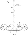
Figure 4 is a cross-sectional view of the trolley base ofFigure 3 with the brake device in the lowered position; -
Figure 5 is a side view of part of the brake device in the raised position; -
Figure 6 is a side view of part of the brake device in the lowered position; -
Figure 7 is a perspective detail view of part of the brake pad viewed from below; -
Figure 8 is an enlarged view of part of the release mechanism. -
Figure 1 illustrates atypical trolley 10 for medical equipment in which abrake device 12 in accordance with the present invention is incorporated. Thetrolley 10 in this example has a centralupright pole 14, to which medical equipment may be attached, and abase 16 comprising a number of radiatingfeet 18 each attached to a swivelcastor wheel assembly 20. Thebase 16 is covered by aprotective skirt 44 which is described further below. In this figure, theskirt 44 is shown transparent in order to illustrate the components below. - The
brake device 12 comprises adeformable brake pad 22 secured to arelease mechanism 26. Thebrake pad 22 is located substantially centrally beneath thetrolley base 16, radially inwardly of thewheels 20 as seen inFigure 2 . In the raised or retracted position, thebrake pad 22 is held just beneath theradiating feet 18 and spaced above the floor surface on which thewheels 20 rest, as inFigure 3 . In this position, thetrolley 10 can move freely. Therelease mechanism 26, which is described further below, is operable to lower thebrake pad 22 so that it contacts the floor surface to apply a braking force and inhibit or prevent movement of thetrolley 10, as shown inFigure 4 . - The
brake pad 22 is a body of deformable or compressible material with non-slip or high friction properties so that it will resist slipping once it is pressed into contact with another surface. In this example, thebrake pad 22 comprises a circular moulded mat with a plurality of projections orfingers 28. The mat is attached to the underside of acircular backing plate 24 so that thefingers 28 extend downwardly as shown inFigure 5 . The mat is formed of a flexible elastomeric material such as rubber or silicone. When thebrake pad 22 contacts the floor, thefingers 28 deform or bend under the weight of thebrake device 12, and optionally an additional biasing means as described further below, as shown inFigure 6 , thereby increasing the surface area in contact with the floor surface, to provide a braking effect on thetrolley 10. Thefingers 28 may be conical, or pyramid-shaped with a number of flat faces as shown inFigure 7 . However, the shape and dimensions of thefingers 28 may be altered as desired to provide the appropriate flexibility and to give the required braking effect when contacting the floor surface. Thebrake pad 22 may be formed of any suitable deformable or compressible material, such as a foam or sponge. - The
release mechanism 26 comprises thebacking plate 24 and anelongate extension member 30 which extends upwardly from thebacking plate 24. Theextension member 30 is preferably slideably received within thecentral pole 14 of thetrolley 10 and can be moved up and down within thepole 14 in order to raise and lower thebrake pad 22. - In this example, the
release mechanism 26 may further comprise ahandle 34 projecting laterally from an upper region of theextension member 30 through aslot 36 in thepole 14, as seen inFigures 1 and8 . Theslot 36 is shaped to hold thehandle 34 in an upper position in which thebrake pad 22 is raised above the floor, and to allow it to be moved to a lower position in which thebrake pad 22 is pressed against the floor. For example, theslot 36 may be in the form of an inverted bayonet fitting or arch shape with one leg of the arch extending further down thepole 14 than the other. When thehandle 34 is received in theupper end position 38 of theslot 36 theextension member 30,backing plate 24 andbrake pad 22 are held in the raised or retracted position. To release thebrake device 12, thehandle 34 is lifted over theapex 40 of theslot 36 and moved down to thelower end position 42. - The
release mechanism 26 is configured and dimensioned such that in the lowered position, thebrake pad 22 is pushed down against the floor surface so that thebrake pad 22 will deform or compress and the projectingfingers 28 will bend in order to increase the contact area with the floor in order to exert a significant braking force on thetrolley 10. An additional biasing means 32 may be provided to increase the downward force on thebrake pad 22. For example, spring means may be provided which pushes downwardly on theextension member 30. Such spring means may be located within thepole 14 between a stop and the top of theextension member 30. Alternatively, spring means may be provided between thebase 16 of thetrolley 10 and thebacking plate 24. In the raised position, the spring means is held in a compressed state and cannot extend because thehandle 34 is retained in theupper end 38 of theslot 36. Once thehandle 34 is moved to the lower end of the slot, the spring means is able to extend and exert a downward force on thebrake pad 22. Alternatively, the weight of theextension member 30 and thebacking plate 24 may be sufficient to press thebrake pad 22 against the floor, or additional weight may be added. For example, aheavy disc 46 may be provided on the top of thebacking plate 24 as shown inFigure 2 . The weight of thedisc 46 will depend on the material used for thebrake pad 22 and the configuration of thefingers 28 and will be chosen to ensure an optimal amount of friction with the floor surface. - It will be appreciated that many other forms of release mechanism could be employed. The release mechanism should be a simple robust mechanism, which is easily accessible for the user without the need to bend down, and straightforward to operate, to encourage a user to make use of the brake device. Locating the
release mechanism 26 within part of the trolley frame is not essential but is advantageous because it minimises the risk of trapping a user's fingers or other items between relatively moving parts of the device. Positioning thebrake pad 22 beneath the trolley base and not projecting out beyond thewheels 20 ensures thebrake device 12 does not form a trip hazard. - In a further development, a
protective skirt 44 may be fitted on thetrolley 10 over thebase 16 as shown inFigures1-4 . This prevents a user tripping over theradiating feet 18 and also prevents cables or other items becoming tangled with thefeet 18, thewheels 20 or thebrake device 12. Theskirt 44 may be a moulded plastic shell which fits over thepole 14 and thebase 16 and is dimensioned to sit a few millimetres above the floor surface so that it will not interfere with the rolling action of thetrolley 10. - The
brake device 12 of the present invention has been described with asingle brake pad 22 fitted to a trolley with a singlecentral upright pole 14. However, it will be appreciated that thebrake device 12 can be adapted for use with other types of trolley. For larger trolleys with more than one upright and a base covering a larger surface area, more than one brake pad may be provided beneath the trolley base. The release mechanism may be adapted to fit the trolley configuration as required. For example, it may be located in one or more of the uprights, with a suitable linkage to connect the release mechanism to the or each brake pad. It is preferable if a single release mechanism operates all the brake pads, to retain the simplicity of use and encourage a user to apply the brake when required. - Thus, the present invention provides a simple but effective braking device for a trolley, which can be operated by the user in one movement and without bending down, to encourage the user to make use of the brake device when required.
Claims (9)
- A trolley having a base mounted on a plurality of wheels, and a brake comprising at least one deformable brake pad located beneath the trolley base and a release mechanism operable to move the brake pad between a raised position in which it is spaced above a floor surface on which the trolley wheels rest, and a lowered position in which the brake pad is pressed against the floor surface under the weight of the brake device to exert a braking force on the trolley.
- A trolley as claimed in claim 1, wherein the brake pad comprises a mat with a plurality of deformable elongate projections.
- A trolley as claimed in claim 2, further comprising a backing plate with upper and lower surfaces, wherein the brake pad is mounted on the lower surface with the projections depending downwardly and wherein the release mechanism is connected to the upper surface.
- A trolley as claimed in claim 3, wherein the release mechanism comprises an extension member extending upwardly from the backing plate and a handle operable by a user to raise and lower the elongate member.
- A trolley as claimed in claim 4, wherein the release mechanism further comprises guide means with end stops to define the raised and lowered positions and to guide movement of the handle between the end stops.
- A trolley as claimed in claim 5, wherein the elongate member is movably located within a hollow part of the trolley and the guide means comprises a slot formed in the hollow part through which the handle extends.
- A trolley as claimed in any preceding claim, further comprising biasing means to bias the brake pad against the floor surface in the lowered position.
- A trolley as claimed in claim 7, wherein the biasing means comprises spring means located between a part of the trolley and the brake and configured to bias the brake pad downwardly when it is in the lowered position.
- A trolley as claimed in claim 7, wherein the biasing means comprises a weight mounted on the release mechanism.
Applications Claiming Priority (1)
| Application Number | Priority Date | Filing Date | Title |
|---|---|---|---|
| GB1805163.1A GB2572551B (en) | 2018-03-29 | 2018-03-29 | Ground engaging brake device for a trolley |
Publications (1)
| Publication Number | Publication Date |
|---|---|
| EP3545931A1 true EP3545931A1 (en) | 2019-10-02 |
Family
ID=62142368
Family Applications (1)
| Application Number | Title | Priority Date | Filing Date |
|---|---|---|---|
| EP19162216.6A Withdrawn EP3545931A1 (en) | 2018-03-29 | 2019-03-12 | Trolley brake assembly |
Country Status (5)
| Country | Link |
|---|---|
| US (1) | US10960911B2 (en) |
| EP (1) | EP3545931A1 (en) |
| JP (1) | JP2019172249A (en) |
| CN (1) | CN110316236A (en) |
| GB (1) | GB2572551B (en) |
Families Citing this family (3)
| Publication number | Priority date | Publication date | Assignee | Title |
|---|---|---|---|---|
| CN113442983B (en) * | 2020-03-25 | 2023-04-07 | 江苏南源消防工程有限公司 | Pulling device of foam fire extinguishing device |
| US20230046235A1 (en) * | 2021-08-13 | 2023-02-16 | Aqua Conscience Holdings LLC | Brake/ballast assembly for a movable structure |
| CN115459795A (en) * | 2022-09-06 | 2022-12-09 | 深圳市城市公共安全技术研究院有限公司 | Internet big data information processing terminal |
Citations (4)
| Publication number | Priority date | Publication date | Assignee | Title |
|---|---|---|---|---|
| US3231050A (en) * | 1963-10-07 | 1966-01-25 | John C Belyeu | Combined brake and load sustaining device for trucks and carts |
| US3715015A (en) * | 1971-12-22 | 1973-02-06 | A Morris | Brake for rollable platform |
| US4302025A (en) * | 1980-02-22 | 1981-11-24 | Kansa Corporation | Paper sheet material handling cart having central brake assembly |
| KR20160089817A (en) * | 2015-01-20 | 2016-07-28 | 김정일 | Brake for handcart |
Family Cites Families (19)
| Publication number | Priority date | Publication date | Assignee | Title |
|---|---|---|---|---|
| US2747692A (en) * | 1952-09-29 | 1956-05-29 | Tracy S Holmes | Foot actuated, ground engaging brake for hand trucks and the like |
| US3405783A (en) * | 1966-06-10 | 1968-10-15 | Westinghouse Electric Corp | Releasable brake constructions for vehicles |
| GB1498022A (en) * | 1975-10-16 | 1978-01-18 | Ellison Hospital Equipment Ltd | Braking system |
| JPS563053U (en) * | 1979-06-22 | 1981-01-12 | ||
| JPS56141802U (en) * | 1980-03-26 | 1981-10-26 | ||
| JPS59151870U (en) * | 1983-03-31 | 1984-10-11 | 花岡車輌株式会社 | hand truck |
| US4648613A (en) * | 1985-07-17 | 1987-03-10 | Hennessy Products, Inc. | Safety design newspaper insert cart |
| US4886286A (en) * | 1986-11-12 | 1989-12-12 | Whorton Iii Robert B | Portable concession stand |
| US6860496B2 (en) * | 1999-12-30 | 2005-03-01 | First Data Corporation | Dolly system for vehicle movement |
| AUPR387001A0 (en) * | 2001-03-21 | 2001-04-12 | Hilltrolley Pty Ltd | Brake for a vehicle |
| KR20100106833A (en) * | 2009-03-24 | 2010-10-04 | 박종화 | Safety chair |
| KR20100116329A (en) * | 2009-04-22 | 2010-11-01 | 김성연 | Moving chair that can be hold |
| JP2011240892A (en) * | 2010-05-21 | 2011-12-01 | Koichiro Omori | Device and method of ensuring safety of cart |
| IN2014MU00244A (en) * | 2014-01-23 | 2015-09-11 | Shivani Scient Ind Private Ltd | |
| WO2016125923A1 (en) * | 2015-02-03 | 2016-08-11 | (주)코젤 | Apparatus for fixing electric chair |
| AU2016267389B2 (en) * | 2015-05-22 | 2021-08-12 | Integrated Technology Services Ip Pty Ltd | Coin bin |
| CN105711334A (en) * | 2016-05-06 | 2016-06-29 | 成都理工大学 | Support-rod-braked trundle |
| JP6281036B1 (en) * | 2017-03-25 | 2018-02-14 | 敬一郎 酒井 | Wheelbarrow brake equipment |
| CN107599743A (en) * | 2017-08-14 | 2018-01-19 | 嘉兴市兴腾脚轮有限公司 | Brake shoes is worn from early warning shopping cart castor |
-
2018
- 2018-03-29 GB GB1805163.1A patent/GB2572551B/en not_active Expired - Fee Related
-
2019
- 2019-03-12 EP EP19162216.6A patent/EP3545931A1/en not_active Withdrawn
- 2019-03-18 US US16/356,848 patent/US10960911B2/en active Active
- 2019-03-27 CN CN201910238280.2A patent/CN110316236A/en active Pending
- 2019-03-29 JP JP2019065579A patent/JP2019172249A/en active Pending
Patent Citations (4)
| Publication number | Priority date | Publication date | Assignee | Title |
|---|---|---|---|---|
| US3231050A (en) * | 1963-10-07 | 1966-01-25 | John C Belyeu | Combined brake and load sustaining device for trucks and carts |
| US3715015A (en) * | 1971-12-22 | 1973-02-06 | A Morris | Brake for rollable platform |
| US4302025A (en) * | 1980-02-22 | 1981-11-24 | Kansa Corporation | Paper sheet material handling cart having central brake assembly |
| KR20160089817A (en) * | 2015-01-20 | 2016-07-28 | 김정일 | Brake for handcart |
Also Published As
| Publication number | Publication date |
|---|---|
| GB201805163D0 (en) | 2018-05-16 |
| GB2572551A (en) | 2019-10-09 |
| US20190300038A1 (en) | 2019-10-03 |
| GB2572551B (en) | 2020-06-17 |
| CN110316236A (en) | 2019-10-11 |
| US10960911B2 (en) | 2021-03-30 |
| JP2019172249A (en) | 2019-10-10 |
Similar Documents
| Publication | Publication Date | Title |
|---|---|---|
| US10960911B2 (en) | Brake device for a trolley | |
| US20150351986A1 (en) | Retractable Wheel Base | |
| US20130112832A1 (en) | Systems and Methods for Supporting Mattresses | |
| US9011302B2 (en) | Thigh exercise device | |
| KR20100106833A (en) | Safety chair | |
| KR200475891Y1 (en) | Antislip device for a wheelchair | |
| US10111793B1 (en) | IV pole stand stop | |
| CN207928453U (en) | A kind of braking mechanism for the treatment of center | |
| KR101089997B1 (en) | Apparatus for brake of walking support machine | |
| CN111345969A (en) | Traction device for orthopedics | |
| CN210144221U (en) | Easy-to-get-up seat for old people | |
| US20120291829A1 (en) | Devices For A Walker | |
| US20170290427A1 (en) | Wheel-Mounted Carpet Protector | |
| CN213466690U (en) | Body-building sliding plate of strength type | |
| EP3031436A1 (en) | Turning device | |
| KR101589940B1 (en) | Apparatus for assisting walking | |
| US6315085B1 (en) | Semi automatic brake applicator for wheel chairs | |
| CN211049924U (en) | Medical bed with pedals | |
| CN215021793U (en) | Orthopedic nursing anti-skidding walking stick | |
| CN211583565U (en) | Foot stool for operating room | |
| CN210749879U (en) | Stretcher for orthopedics | |
| US11554066B2 (en) | Patient slider device | |
| CN211130229U (en) | Movable shoe cabinet | |
| KR101978844B1 (en) | Brake device for wheelchair | |
| NL8601554A (en) | LIFTING DEVICE FOR THE DISABLED. |
Legal Events
| Date | Code | Title | Description |
|---|---|---|---|
| PUAI | Public reference made under article 153(3) epc to a published international application that has entered the european phase |
Free format text: ORIGINAL CODE: 0009012 |
|
| STAA | Information on the status of an ep patent application or granted ep patent |
Free format text: STATUS: THE APPLICATION HAS BEEN PUBLISHED |
|
| AK | Designated contracting states |
Kind code of ref document: A1 Designated state(s): AL AT BE BG CH CY CZ DE DK EE ES FI FR GB GR HR HU IE IS IT LI LT LU LV MC MK MT NL NO PL PT RO RS SE SI SK SM TR |
|
| AX | Request for extension of the european patent |
Extension state: BA ME |
|
| STAA | Information on the status of an ep patent application or granted ep patent |
Free format text: STATUS: REQUEST FOR EXAMINATION WAS MADE |
|
| 17P | Request for examination filed |
Effective date: 20200130 |
|
| RBV | Designated contracting states (corrected) |
Designated state(s): AL AT BE BG CH CY CZ DE DK EE ES FI FR GB GR HR HU IE IS IT LI LT LU LV MC MK MT NL NO PL PT RO RS SE SI SK SM TR |
|
| STAA | Information on the status of an ep patent application or granted ep patent |
Free format text: STATUS: EXAMINATION IS IN PROGRESS |
|
| STAA | Information on the status of an ep patent application or granted ep patent |
Free format text: STATUS: EXAMINATION IS IN PROGRESS |
|
| 17Q | First examination report despatched |
Effective date: 20201117 |
|
| STAA | Information on the status of an ep patent application or granted ep patent |
Free format text: STATUS: THE APPLICATION IS DEEMED TO BE WITHDRAWN |
|
| 18D | Application deemed to be withdrawn |
Effective date: 20221001 |