EP3545839A1 - Multispektrale medizinische bilderzeugungsvorrichtungen und verfahren dafür - Google Patents
Multispektrale medizinische bilderzeugungsvorrichtungen und verfahren dafür Download PDFInfo
- Publication number
- EP3545839A1 EP3545839A1 EP19175580.0A EP19175580A EP3545839A1 EP 3545839 A1 EP3545839 A1 EP 3545839A1 EP 19175580 A EP19175580 A EP 19175580A EP 3545839 A1 EP3545839 A1 EP 3545839A1
- Authority
- EP
- European Patent Office
- Prior art keywords
- target tissue
- objective lens
- optical axis
- positioning
- distance
- Prior art date
- Legal status (The legal status is an assumption and is not a legal conclusion. Google has not performed a legal analysis and makes no representation as to the accuracy of the status listed.)
- Withdrawn
Links
- 238000002059 diagnostic imaging Methods 0.000 title claims abstract description 26
- 238000000034 method Methods 0.000 title claims description 35
- QVGXLLKOCUKJST-UHFFFAOYSA-N atomic oxygen Chemical compound [O] QVGXLLKOCUKJST-UHFFFAOYSA-N 0.000 claims abstract description 62
- 229910052760 oxygen Inorganic materials 0.000 claims abstract description 62
- 239000001301 oxygen Substances 0.000 claims abstract description 62
- 238000005286 illumination Methods 0.000 claims abstract description 57
- 230000003287 optical effect Effects 0.000 claims description 45
- 238000003384 imaging method Methods 0.000 claims description 7
- 230000000007 visual effect Effects 0.000 claims description 2
- XUMBMVFBXHLACL-UHFFFAOYSA-N Melanin Chemical compound O=C1C(=O)C(C2=CNC3=C(C(C(=O)C4=C32)=O)C)=C2C4=CNC2=C1C XUMBMVFBXHLACL-UHFFFAOYSA-N 0.000 description 40
- 238000012937 correction Methods 0.000 description 39
- 239000000872 buffer Substances 0.000 description 24
- 108010054147 Hemoglobins Proteins 0.000 description 19
- 102000001554 Hemoglobins Human genes 0.000 description 19
- 238000012545 processing Methods 0.000 description 18
- 230000015654 memory Effects 0.000 description 17
- 230000008569 process Effects 0.000 description 16
- 238000001514 detection method Methods 0.000 description 15
- 238000010586 diagram Methods 0.000 description 14
- 210000003462 vein Anatomy 0.000 description 14
- 238000004364 calculation method Methods 0.000 description 11
- 230000008859 change Effects 0.000 description 11
- 238000009432 framing Methods 0.000 description 11
- 238000006213 oxygenation reaction Methods 0.000 description 9
- 238000006073 displacement reaction Methods 0.000 description 8
- 238000005096 rolling process Methods 0.000 description 7
- 230000000287 tissue oxygenation Effects 0.000 description 7
- 210000005166 vasculature Anatomy 0.000 description 6
- 230000002123 temporal effect Effects 0.000 description 5
- 238000012800 visualization Methods 0.000 description 5
- 238000011088 calibration curve Methods 0.000 description 4
- 230000003635 deoxygenating effect Effects 0.000 description 4
- 230000000873 masking effect Effects 0.000 description 4
- 238000005259 measurement Methods 0.000 description 4
- 230000009466 transformation Effects 0.000 description 4
- 238000010521 absorption reaction Methods 0.000 description 3
- 230000008901 benefit Effects 0.000 description 3
- 230000000694 effects Effects 0.000 description 3
- 230000006870 function Effects 0.000 description 3
- 238000004519 manufacturing process Methods 0.000 description 3
- 239000011159 matrix material Substances 0.000 description 3
- 230000010412 perfusion Effects 0.000 description 3
- 238000001454 recorded image Methods 0.000 description 3
- 238000003860 storage Methods 0.000 description 3
- 238000012360 testing method Methods 0.000 description 3
- 238000004458 analytical method Methods 0.000 description 2
- 210000003484 anatomy Anatomy 0.000 description 2
- 230000009286 beneficial effect Effects 0.000 description 2
- 238000004422 calculation algorithm Methods 0.000 description 2
- 238000000701 chemical imaging Methods 0.000 description 2
- 238000000605 extraction Methods 0.000 description 2
- 238000012306 spectroscopic technique Methods 0.000 description 2
- 238000001429 visible spectrum Methods 0.000 description 2
- 238000003491 array Methods 0.000 description 1
- 238000010420 art technique Methods 0.000 description 1
- 210000004204 blood vessel Anatomy 0.000 description 1
- 230000000295 complement effect Effects 0.000 description 1
- 239000002872 contrast media Substances 0.000 description 1
- 238000010219 correlation analysis Methods 0.000 description 1
- 125000004122 cyclic group Chemical group 0.000 description 1
- 230000001419 dependent effect Effects 0.000 description 1
- 238000009826 distribution Methods 0.000 description 1
- 230000003760 hair shine Effects 0.000 description 1
- 108010047412 hemoglobin L Proteins 0.000 description 1
- 230000006872 improvement Effects 0.000 description 1
- 230000002452 interceptive effect Effects 0.000 description 1
- 230000007774 longterm Effects 0.000 description 1
- 238000013507 mapping Methods 0.000 description 1
- 230000005855 radiation Effects 0.000 description 1
- 230000004044 response Effects 0.000 description 1
- 239000004065 semiconductor Substances 0.000 description 1
- 230000035945 sensitivity Effects 0.000 description 1
- 230000000153 supplemental effect Effects 0.000 description 1
- XLYOFNOQVPJJNP-UHFFFAOYSA-N water Substances O XLYOFNOQVPJJNP-UHFFFAOYSA-N 0.000 description 1
- 230000003936 working memory Effects 0.000 description 1
Images






Classifications
-
- A—HUMAN NECESSITIES
- A61—MEDICAL OR VETERINARY SCIENCE; HYGIENE
- A61B—DIAGNOSIS; SURGERY; IDENTIFICATION
- A61B5/00—Measuring for diagnostic purposes; Identification of persons
- A61B5/145—Measuring characteristics of blood in vivo, e.g. gas concentration or pH-value ; Measuring characteristics of body fluids or tissues, e.g. interstitial fluid or cerebral tissue
- A61B5/1455—Measuring characteristics of blood in vivo, e.g. gas concentration or pH-value ; Measuring characteristics of body fluids or tissues, e.g. interstitial fluid or cerebral tissue using optical sensors, e.g. spectral photometrical oximeters
- A61B5/14551—Measuring characteristics of blood in vivo, e.g. gas concentration or pH-value ; Measuring characteristics of body fluids or tissues, e.g. interstitial fluid or cerebral tissue using optical sensors, e.g. spectral photometrical oximeters for measuring blood gases
-
- A—HUMAN NECESSITIES
- A61—MEDICAL OR VETERINARY SCIENCE; HYGIENE
- A61B—DIAGNOSIS; SURGERY; IDENTIFICATION
- A61B5/00—Measuring for diagnostic purposes; Identification of persons
- A61B5/02—Detecting, measuring or recording for evaluating the cardiovascular system, e.g. pulse, heart rate, blood pressure or blood flow
- A61B5/02007—Evaluating blood vessel condition, e.g. elasticity, compliance
-
- A—HUMAN NECESSITIES
- A61—MEDICAL OR VETERINARY SCIENCE; HYGIENE
- A61B—DIAGNOSIS; SURGERY; IDENTIFICATION
- A61B5/00—Measuring for diagnostic purposes; Identification of persons
- A61B5/02—Detecting, measuring or recording for evaluating the cardiovascular system, e.g. pulse, heart rate, blood pressure or blood flow
- A61B5/026—Measuring blood flow
- A61B5/0261—Measuring blood flow using optical means, e.g. infrared light
-
- A—HUMAN NECESSITIES
- A61—MEDICAL OR VETERINARY SCIENCE; HYGIENE
- A61B—DIAGNOSIS; SURGERY; IDENTIFICATION
- A61B5/00—Measuring for diagnostic purposes; Identification of persons
- A61B5/145—Measuring characteristics of blood in vivo, e.g. gas concentration or pH-value ; Measuring characteristics of body fluids or tissues, e.g. interstitial fluid or cerebral tissue
- A61B5/1455—Measuring characteristics of blood in vivo, e.g. gas concentration or pH-value ; Measuring characteristics of body fluids or tissues, e.g. interstitial fluid or cerebral tissue using optical sensors, e.g. spectral photometrical oximeters
-
- A—HUMAN NECESSITIES
- A61—MEDICAL OR VETERINARY SCIENCE; HYGIENE
- A61B—DIAGNOSIS; SURGERY; IDENTIFICATION
- A61B5/00—Measuring for diagnostic purposes; Identification of persons
- A61B5/48—Other medical applications
- A61B5/4887—Locating particular structures in or on the body
- A61B5/489—Blood vessels
-
- A—HUMAN NECESSITIES
- A61—MEDICAL OR VETERINARY SCIENCE; HYGIENE
- A61B—DIAGNOSIS; SURGERY; IDENTIFICATION
- A61B5/00—Measuring for diagnostic purposes; Identification of persons
- A61B5/70—Means for positioning the patient in relation to the detecting, measuring or recording means
-
- A—HUMAN NECESSITIES
- A61—MEDICAL OR VETERINARY SCIENCE; HYGIENE
- A61B—DIAGNOSIS; SURGERY; IDENTIFICATION
- A61B5/00—Measuring for diagnostic purposes; Identification of persons
- A61B5/72—Signal processing specially adapted for physiological signals or for diagnostic purposes
- A61B5/7203—Signal processing specially adapted for physiological signals or for diagnostic purposes for noise prevention, reduction or removal
- A61B5/7207—Signal processing specially adapted for physiological signals or for diagnostic purposes for noise prevention, reduction or removal of noise induced by motion artifacts
-
- A—HUMAN NECESSITIES
- A61—MEDICAL OR VETERINARY SCIENCE; HYGIENE
- A61B—DIAGNOSIS; SURGERY; IDENTIFICATION
- A61B5/00—Measuring for diagnostic purposes; Identification of persons
- A61B5/74—Details of notification to user or communication with user or patient; User input means
- A61B5/742—Details of notification to user or communication with user or patient; User input means using visual displays
-
- A—HUMAN NECESSITIES
- A61—MEDICAL OR VETERINARY SCIENCE; HYGIENE
- A61B—DIAGNOSIS; SURGERY; IDENTIFICATION
- A61B2576/00—Medical imaging apparatus involving image processing or analysis
- A61B2576/02—Medical imaging apparatus involving image processing or analysis specially adapted for a particular organ or body part
-
- G—PHYSICS
- G16—INFORMATION AND COMMUNICATION TECHNOLOGY [ICT] SPECIALLY ADAPTED FOR SPECIFIC APPLICATION FIELDS
- G16H—HEALTHCARE INFORMATICS, i.e. INFORMATION AND COMMUNICATION TECHNOLOGY [ICT] SPECIALLY ADAPTED FOR THE HANDLING OR PROCESSING OF MEDICAL OR HEALTHCARE DATA
- G16H30/00—ICT specially adapted for the handling or processing of medical images
- G16H30/40—ICT specially adapted for the handling or processing of medical images for processing medical images, e.g. editing
Definitions
- This disclosure relates to medical imaging, more specifically, to multispectral medical imaging devices and methods thereof.
- Multispectral medical imaging is known to be used to measure oxygenation of blood vessels and tissue. It is an important tool. Quantified oxygenation data can assist medical professionals in providing better patient care.
- a multispectral medical imaging device includes a plurality of illumination devices arranged to illuminate a target tissue.
- the illumination devices are configured to emit light of different near-infrared wavelength bands.
- the device further includes an objective lens, a near-infrared image sensor positioned to capture image frames reflected from the target tissue through the objective lens, and a visible-light image sensor positioned to capture image frames reflected from the target tissue through the objective lens.
- a processor is connected to the near-infrared image sensor, the visible-light image sensor, and the plurality of illumination devices. The processor is configured to modulate near-infrared light output of the plurality of illumination devices to illuminate the target tissue.
- the processor is further configured to determine reflectance intensities from the image frames captured by the near-infrared image sensor and to generate a dynamic tissue oxygen saturation map of the target tissue using the reflectance intensities.
- the device further includes an output device connected to the processor for displaying the dynamic tissue oxygen saturation map.
- the processor can be configured to generate the dynamic tissue oxygen saturation map of the target tissue by comparing the reflectance intensities to a reference standard.
- the plurality of illumination devices can be arranged in a ring around the objective lens.
- the plurality of illumination devices can include at least four illumination devices having near-infrared wavelength bands with nominal peak wavelengths of about 740, 780, 850 and 940 nm.
- the device can further include a dichroic beam splitter positioned between the objective lens and the near-infrared and visible-light image sensors, the dichroic beam splitter arranged to split light from the objective lens between the near-infrared and visible-light image sensors.
- the device can further include a white-light illumination device arranged to illuminate the target tissue with visible light.
- the output device can include a display for viewing by a clinician.
- the output device can include a projector positioned to project the dynamic tissue oxygen saturation map onto a skin surface over the target tissue.
- the processor can be configured to modulate the plurality of illumination devices to illuminate the target tissue by sequentially driving the plurality of illumination devices, wherein each image frame in a sequence of the image frames corresponds to illumination of the target tissue by a different wavelength band.
- the processor can be configured to perform rolling processing on a window of image frames corresponding to illumination of the target tissue by each of the illumination devices.
- a frame rate of the dynamic tissue oxygen saturation map can be approximately equal to a combined frequency of modulation of all of the plurality of illumination devices.
- the processor can be further configured to perform motion correction on image frames captured by the near-infrared image sensor, the motion correction comprising selecting a reference frame from the image frames and calculating image registration coefficients for at least one subsequent frame of the image frames.
- Calculating image registration coefficients can include performing a space transformation on the reference frame and the at least one subsequent frame.
- Calculating image registration coefficients can include performing feature detection on the reference frame and the at least one subsequent frame.
- the processor can be further configured to calculate image registration coefficients for the motion correction using sub-regions of the image frames captured by the near-infrared image sensor, the sub-regions having dimensions smaller than a size of the image frames and being located away from edges of the image frames.
- the processor can be further configured to perform motion correction on image frames captured by the visible-light image sensor.
- the motion correction can include performing feature detection including detection of an ink mark on a skin surface over the target tissue.
- the motion correction can include performing feature detection including detection of body hair on skin over the target tissue.
- the motion correction can include performing feature detection including detection of vasculature of the target tissue.
- the processor can be further configured to use output of the visible-light image sensor to determine a correction for melanin in skin over the target tissue and to apply the correction to the reflectance intensities of the image frames captured by the near-infrared image sensor.
- the processor can be configured to determine the correction from a predetermined relationship between visible light reflected intensity and melanin concentration.
- the processor can be further configured to use the near-infrared image sensor to capture at least one ambient infrared image of the target tissue when controlling all of the illumination devices to not illuminate the target tissue, and the processor can be further configured to subtract the ambient infrared image from the captured image frames.
- the processor can be further configured to repeatedly capture ambient infrared images and to subtract a most recent ambient infrared image from subsequently captured image frames.
- the processor can be further configured to trigger capture of the ambient infrared image based on a change in ambient infrared illumination that exceeds a threshold.
- the device can further include an ambient-light sensor connected to the processor and configured to detect the change in ambient infrared illumination.
- the device can further include a visible-light image sensor connected to the processor and configured to detect a change in ambient visible illumination indicative of the change in ambient infrared illumination.
- a visible-light image sensor connected to the processor and configured to detect a change in ambient visible illumination indicative of the change in ambient infrared illumination.
- the processor can be further configured to mask a region of the dynamic tissue oxygen saturation map where intensities of the region in image frames of different near-infrared wavelength bands indicate a threshold amount of curvature of the target tissue.
- the processor can be further configured to perform a temporal difference operation on a sequence of frames of the dynamic tissue oxygen saturation map with respect to a reference frame of the dynamic tissue oxygen saturation map.
- the processor can be further configured to use the image frames to calculate a rate of desaturation of hemoglobin in the target tissue over a period of time for determining a venous or arterial blockage.
- the processor can be further configured to use the image frames to identify veins in the target tissue and to modify reflectance intensities to compensate for oxygenation or deoxygenating at the veins when generating the dynamic tissue oxygen saturation map.
- the device can further include at least one laser positioned to emit a plurality of laser points onto a skin surface over the target tissue, the laser points for assisting manual positioning of the device with respect to the target tissue.
- the device can further include a visible-light image sensor connected to the processor for capturing light from the laser points reflected from the skin surface, and the processor can be further configured to include the laser points in the dynamic tissue oxygen saturation map.
- the at least one laser can be configured to emit the plurality of laser points at a near-infrared wavelength band detectable by the near-infrared image sensor to include the laser points in the dynamic tissue oxygen saturation map.
- the device can further include optics configured to emit lines of laser light onto the skin surface over the target tissue, the lines of laser light including the laser points.
- the lines of laser light can be arranged as a rectangular box.
- the device can further include a first positioning laser positioned at a first offset distance from an optical axis of the objective lens and aimed at a first angle with respect to the optical axis to emit a first positioning laser spot on a skin surface over the target tissue, and a second positioning laser positioned at a second offset distance from the optical axis of the objective lens and aimed at a second angle with respect to the optical axis to emit a second positioning laser spot on the skin surface.
- the first and second angles can lie in different planes that contain the optical axis, and the first and second offset distances and angles can be selected to cause the first positioning laser spot and the second positioning laser spot to be coincident at the optical axis when the target tissue is a target distance from the objective lens.
- the first and second offset distances and angles can be configured to position the first and second positioning laser spots on one side of the optical axis of the objective lens when a distance from the objective lens to the target tissue is greater than the target distance and to position the first and second positioning laser spots on an opposite side of the target when the distance from the objective lens to the target tissue is less than the target distance.
- the first and second positioning lasers can be positioned at about 90 degrees apart on a circle centered at the optical axis of the objective lens.
- the processor can be further configured to align captured visible-light image frames with captured near-infrared image frames using displacement coefficients stored in memory, the displacement coefficients being predetermined based on image registration performed on at least one standard image captured by both of the near-infrared image sensor and the visible-light image sensor.
- a method for multispectral medical imaging includes illuminating a target tissue with modulated light of different near-infrared wavelength bands, capturing near-infrared image frames reflected from the target tissue, capturing visible-light image frames reflected from the target tissue, determining reflectance intensities from the near-infrared image frames, correcting the reflectance intensities of the near-infrared image frames using information from the visible-light image frames, generate a dynamic tissue oxygen saturation map of the target tissue using the reflectance intensities, and outputting the dynamic tissue oxygen saturation map.
- the multispectral medical imaging devices and methods discussed herein measure reflectance intensities and compare such to a reflectance standard. Ambient light subtraction and melanin correction are also discussed. Near-video or video frame rates can be achieved in real time. A rolling processing technique and logarithmic difference processing can be used to reduce processing overhead and increase frame rates. Image registration can be used to perform motion correction. Regions of high curvature and regions containing vasculature can be removed or masked from processed oxygen saturation concentration images. A difference mode allows for viewing of oxygen saturation differences over a reference frame. Laser framing and positioning arrays are also provided to assist in proper positioning of the device with respect to the target tissue.
- the spectroscopic techniques discussed herein can be used to determine the concentrations of three components of a target tissue, namely, oxygenated hemoglobin, deoxygenated hemoglobin, and melanin.
- Tissue of interest is illuminated by near-infrared (NIR) light, and some of such light is absorbed by oxygenated hemoglobin, deoxygenated hemoglobin, and melanin, and some light is scattered.
- NIR near-infrared
- Absorption amounts are dependent on wavelength and the concentration of each of the components. Scattering depends on wavelength and path length.
- Light which is diffusely reflected back is captured by a near-infrared image sensor.
- the concentration of the three components and the amount of scattered light can be determined by capturing diffusely reflected light from several different wavelength bands of near-infrared light.
- Measured concentration of melanin can be used to correct concentrations of oxygenated and deoxygenated hemoglobin. Light in the visible spectrum can also be captured and processed.
- FIG. 1 shows a diagram of a multispectral medical imaging device 10 according to an embodiment of the present invention.
- the multispectral medical imaging device 10 includes a plurality of illumination devices 12 and 14, an objective lens 16, a beam splitter 18, a near-infrared image sensor 20, and a visible-light image sensor 22.
- Near-infrared illumination devices 12 are arranged to illuminate target tissue 24.
- the near-infrared illumination devices 12 are configured to emit light 26 of different near-infrared wavelength bands.
- Visible-light illumination devices 14 are arranged to illuminate the target tissue 24 with light 28 in the visible spectrum, such as white light.
- the near-infrared and visible light emitted 26, 28 by the illumination devices 12, 14 shines on the same general area of the target tissue in a time-sequenced manner, as will be discussed below.
- the illumination devices 12, 14 may include light-emitting diodes (LEDs) of suitable wavelengths.
- One or more fly's eye condenser lenses can be provided in the path of the illumination devices 12, 14 to improve uniformity of illumination.
- the visible-light illumination devices 14 may be omitted.
- the near-infrared illumination devices 12 are four LEDs having near-infrared wavelength bands with nominal peak wavelengths of about 740, 780, 850, and 940 nm.
- the objective lens 16 is positioned to capture light 30 reflected from the target tissue 24 and to direct such captured light 30 to the beam splitter 18.
- the objective lens 16 can be of any suitable type and configuration. Relay optics may also be provided.
- the size of the region of the target tissue 24 to be analyzed is about 200 mm by about 150 mm, and the objective lens 16 can be appropriately selected for such area.
- the beam splitter 18 can be a dichroic beam splitter, or similar optical device.
- the beam splitter 18 is arranged to split the captured light 30 received from the objective lens 16 into near-infrared light 32 and visible light 34.
- the beam splitter 18 is arranged to direct the captured near-infrared light 32 to the near-infrared image sensor 20 and to direct the captured visible light 34 to the visible-light image sensor 22.
- the beam splitter 18 directs wavelengths of less than about 700 nm to the visible-light image sensor 22 and directs wavelengths of greater than about 700 nm to the near-infrared image sensor 20.
- the near-infrared image sensor 20 is positioned to capture near-infrared light 32 reflected from the target tissue 24 through the objective lens 16.
- the near-infrared image sensor 20 is configured to capture the near-infrared light 32 as a sequence image frames at a frequency in excess of a suitable video frame rates (e.g., greater than 24 frames per second or FPS). Adjacent frames of different near-infrared wavelength bands are combined into a sequence of oxygen saturation frames at a reduce frame rate, such as a video frame rate (e.g., 24 FPS) to produce a dynamic tissue oxygen saturation map, as will be discussed in detail below.
- the near-infrared image sensor 20 may include a complementary metal-oxide-semiconductor (CMOS) device with high sensitivity to near-infrared wavelengths.
- CMOS complementary metal-oxide-semiconductor
- the visible-light image sensor 22 is positioned to capture visible light 34 reflected from the target tissue 24 through the objective lens 16. Visible-light image frames can be included in the sequence of image frames capturing the near-infrared light 32, and can be captured that the same rate as each near-infrared wavelength band or at a lower rate.
- the visible-light sensor 22 may include a Bayer-masked RGB CMOS device.
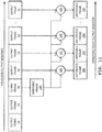
- the multispectral medical imaging device 10 further includes an illumination driver 40, an image capture buffer 42, memory 44, a processor 46, a display 48, and a user interface 52.
- the illumination driver 40 is connected to the processor 46.
- the illumination driver 40 is a circuit that controllably provides driving power to the illumination devices 12, 14 and operates the illumination devices 12, 14 according to a sequence controlled by the processor 46.
- the image capture buffer 42 includes memory that is connected to the image sensors 20, 22 and is operable to buffer image frames captured by the near-infrared and visible-light image sensors 20, 22.
- the image capture buffer 42 is connected to the processor 46 to allow the processor 46 to control the capture sequence of the image frames.
- the image capture buffer 42 is also connected to the memory 44, which provides storage space for captured and/or processed image frames.
- the memory 44 is connected to the processor 46 and stores captured and/or processed image frames and one or more programs that are executable by the processor 46 to implement the functionality described herein.
- the memory 44 provides short-term working memory space for temporary variable and intermediate processed values or images.
- the memory can also provide long-term storage for indefinite recording of dynamic tissue oxygenation maps and similar.
- the memory 44 can include any single or combination of devices such as random-access memory (RAM), read-only memory (ROM), flash memory, a hard-disk drive, an optical storage drive, and the like.
- the processor 46 may be any kind of microprocessor, central processing unit (CPU), multicore processor, field-programmable gate array (FPGA), or the like.
- the processor 46 is configured by one or more programs to modulate near-infrared and visible light 26, 28 output by the plurality of illumination devices 12, 14 to illuminate the target tissue 24.
- the processor 46 can modulate the illumination devices 12, 14 to illuminate the target tissue 24 by sequentially driving the illumination devices 12, 14 and capturing image frames in a sequence, in which each image frame corresponds to illumination of the target tissue by a different wavelength band.
- the processor 46 is further configured, by one or more programs, to determine reflectance intensities from image frames captured by the image sensors 20, 22 and to generate a dynamic tissue oxygen saturation map of the target tissue 24 using the reflectance intensities. This will be discussed in further detail below.
- the display 48 is an output device that is connected to the processor 46 and configured to display the dynamic tissue oxygen saturation map 50, which may be performed in real time and/or at video frame rates.
- the display 48 can be positioned for convenient viewing by a clinician or other user operating the device 10.
- An additional or alternative output device is a projector that projects the dynamic tissue oxygen saturation map onto the target tissue 24, so that the tissue oxygenation map can be viewed as overlaid with the tissue itself.
- the user interface 52 is connected to the processor 46 and can include user interface controls such as buttons, switches, dials, touch-sensitive elements of the display 48, a combination of such, or similar.
- the user interface 52 allows for clinician control of the multispectral medical imaging device 10, including powering on/off, turning on/off various components (e.g., laser framing/focusing), adjusting settings (e.g., thresholds or parameters discussed herein), and making selections such as selecting a reference frame for a temporal difference operation, which will be discussed below.
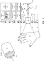
- the multispectral medical imaging device 10 can further include one or both of a laser positioning array 60 and a laser framing array 62.
- the laser positioning array 60 includes two laser sources 64, such as diode lasers, that are arranged to emit laser beams in the general direction of the target tissue 24. Positioning spots are shined onto the target tissue, and the device 10 can be moved backward or forward, away from or towards the target tissue, to cause the positioning spots to move. The positioning spots are used to indicate whether a correct focus position for the objective lens 16 has been reached or whether the device 10 should be moved toward or away from the target tissue 24 to reach the correct focus position. This will be discussed in further detail below.
- the laser framing array 62 includes at least one laser source 66, such as a diode laser, that is arranged to emit at least one beam toward the target tissue 24.
- One or more laser points are shined onto the target tissue, and the device 10 can be rotated, titled, or otherwise move to align the spots on the target tissue 24. This can assist in repeatedly positioning the target tissue 24 with respect to the objective lens 16 at a desired measurement location during subsequent oxygenation measurement sessions. This will be discussed in further detail below.
- the multispectral medical imaging device 10 may further include an ambient-light sensor 68 positioned to detect levels of or changes in background illumination.
- the ambient-light sensor 68 is connected to the processor 46 and may be a visible-light sensor, an infrared light sensor, a combination of such, or similar.
- All or some of the components of the multispectral medical imaging device 10 can be provided in a housing 58, as shown in FIG. 2 .
- the housing 58 can contain an opening for the objective lens 16, and all or some of the illumination devices 12, 14 can be arranged in one or more circular rings around the objective lens 16 to promote spatially uniform illumination.
- the processor 46 is configured to perform rolling processing on a window 70 of image frames 72 corresponding to illumination of the target tissue 24 by each of the near-infrared illumination devices 12.
- Each image frame 72 corresponds to one of the wavelength bands of the near-infrared illumination devices 12. That is, when the rolling window 70 is at the position illustrated, sequential image frames 72 for wavelength bands ⁇ 1, ⁇ 2, ⁇ 3, ⁇ 4 are combined to form an output frame 74 (show as "A"), which is illustrated as wider merely to show the corresponding source image frames 72.
- the rolling window 70 is moved such that sequential image frames 72 for wavelength bands ⁇ 2, ⁇ 3, ⁇ 4, ⁇ 1 are combined to form a subsequent output frame 74 (show as "B"). This process continues for the capture sequence, where the sequence of output frames forms the dynamic tissue oxygen saturation map.
- the frame rate of the dynamic tissue oxygen saturation map is approximately equal to a combined frequency of modulation of all wavelength bands outputted by the near-infrared illumination devices 12. That is, a new output frame 74 can be generated after each new near-infrared image frame 72 is captured by the near-infrared image sensor 20. The output frame rate thus decoupled from the number of different near-infrared frequency bands to be sequentially captured. However, this does not take into account capture of visible-light image frames by the visible-light image sensor 22. This also does not take into account ambient near-infrared image frames captured by the near-infrared image sensor 20 when the near-infrared illumination devices 12 are off.
- Visible-light image frames and ambient near-infrared image frames are captured in sequence with the near-infrared image frame 72, although not necessarily at the same frequency. Increasing the number of visible-light image frames and/or ambient near-infrared image frames captured can reduce overall output frame rate. However this can be beneficial, as such image frames are used for correction purposes.
- FIG. 4 shows an oxygen saturation computation
- Tissue oxygen saturation is derived from a spectroscopic technique based on the Beer-Lambert Law that utilizes the spatially resolved reflectance of the target tissue at four different near-infrared wavebands to determine the relative concentrations (C) of oxygenated hemoglobin (HbO 2 ) and deoxygenated hemoglobin (Hb).
- the image capture buffer 42 can include one or more image buffers 80 for each of the near-infrared wavelength bands ⁇ 1, ⁇ 2, ⁇ 3, ⁇ 4 to capture.
- the image buffers 80 are filled in sequence, as discussed above with respect to the rolling processing.
- the oxygen saturation calculation 82 is performed to obtain tissue oxygen saturation, S T O 2 . That is, after the image buffer 80 for wavelength band ⁇ 1 is filled with a new near-infrared image frame captured by the near-infrared image sensor 20, the oxygen saturation calculation 82 is performed.
- the oxygen saturation calculation 82 is performed again.
- the cyclic filling of the image buffers 80 repeats, with a new oxygen saturation calculation 82 being performed after each fill.
- correction for background or ambient infrared radiation can be performed prior to the oxygen saturation calculation 82.
- a captured ambient image of the target tissue 24 that is stored in an ambient image buffer 84 can be subtracted from each of the contents of the image buffers 80. The results are then forwarded to ambient-corrected image buffers 86.
- the processor 46 and ambient image buffer 84 can be configured to calculate and store a time-average of two or more captured ambient images.
- the ambient-light sensor 68 connected to the processor 46 can be used to trigger capture of an ambient image when the processor 46 determines that there has been a change in ambient infrared illumination that exceeds a threshold.
- the ambient-light sensor 68 can be an infrared light sensor capable of detecting the change directly.
- the ambient-light sensor 68 can be a visible-light sensor that detects a change in ambient visible illumination that may be indicative of the change in ambient infrared illumination.
- Delta or change-based processing 88 is performed on images stored in the ambient-corrected image buffers 86. For each wavelength band, the delta processing 88 uses logarithmic values of a reference image 90 that acts as a reference standard for the particular wavelength band. The delta processing 88 further references a coefficient matrix 92 that relates reflectance intensities to concentrations of oxygenated and deoxygenated hemoglobin. This can reduce processing overhead and increase output frame rate.
- the logarithmic values of the reference image 90 can be pre-calculated based on captured near-infrared images of about 100% diffuse reflectance, and these can be established during an initial calibration process, which may be performed at time of manufacture.
- the delta processing 88 is shown in detail in FIG. 5 . Images for each near-infrared wavelength band undergo the same general processing 88, as executed by the processor 46.
- a logarithm function is applied to reflectance intensities or values for the current image frame.
- stored logarithm values of the previous frame 98 are subtracted from the calculated logarithm values of the current frame obtained in step 94.
- the result of step 96 is subtracted from the logarithmic values of the reference image 90 to obtain a working difference (i.e., temporary values).
- Coefficients 92 are applied to the working difference to obtain concentration changes, at step 102.
- Step 104 includes updating previous values of concentrations of oxygenated and deoxygenated hemoglobin with the concentration changes from step 102 to reflect the change in the intensity of diffuse reflectance for the wavelength band.
- the logarithm values for the current frame are stored as the logarithm values of the previous frame 98. The process then advances to the next frame at step 108.
- the delta processing 88 can be implemented by one or more functions, procedures, formulas, algorithms, a combination of such, or similar. The steps are illustrative and may be performed in a different order or combined into larger steps.
- the logarithm function can be implemented as a lookup table stored in memory 44.
- the left-hand side of the equation represents intensity of light captured by the near-infrared image sensor 20 for the various wavelengths.
- a ⁇ 1 - A ⁇ 4 is representative of the diffuse reflectance.
- the right-hand side has two parts: a constant part and a variable part.
- the constant part contains terms representative of the coefficient of absorption, ⁇ , for the various near-infrared wavelengths of interest for both oxygenated hemoglobin (HbO 2 ) and deoxygenated hemoglobin (Hb).
- the constant part can be pre-computed and stored in the coefficient matrix 92.
- variable part contains concentrations, C, of oxygenated hemoglobin (HbO 2 ) and deoxygenated hemoglobin (Hb) that are the sought values, modified by a factor, L, representative of the thickness of the layer melanin distribution.
- a ⁇ 1 A ⁇ 2 A ⁇ 3 A ⁇ 4 ln 10 ⁇ HbO 2 ⁇ 1 ln 10 ⁇ Hb ⁇ 1 ln 10 ⁇ HbO 2 ⁇ 2 ln 10 ⁇ Hb ⁇ 2 ln 10 ⁇ HbO 2 ⁇ 3 ln 10 ⁇ Hb ⁇ 3 ln 10 ⁇ HbO 2 ⁇ 4 ln 10 ⁇ Hb ⁇ 4 C HbO 2 L C Hb L
- the processor 46 can be configured to perform melanin correction 77 for the skin over the target tissue 24. This can be performed using a Beer-Lambert model using melanin (M), deoxygenated hemoglobin (Hb), and oxygenated hemoglobin (HbO 2 ) as chromophores.
- M melanin
- Hb deoxygenated hemoglobin
- HbO 2 oxygenated hemoglobin
- Measured diffuse reflectance for the each wavelength of interest, A ⁇ 1 - A ⁇ 4, can be modelled according to the following equation, in which R S represents the as-measured intensity of light at a particular wavelength, R O represents the reference image intensity for the wavelength, ⁇ M represents the coefficient of absorption for melanin, and C M is the concentration of melanin in the target tissue.
- R S represents the as-measured intensity of light at a particular wavelength
- R O represents the reference image intensity for the wavelength
- ⁇ M represents the coefficient of absorption for melanin
- C M is the concentration of melanin in the target tissue.
- the effect of melanin reduces the as-measured intensity of light.
- Melanin concentration C M and thickness L are combined into a single parameter Z mel . Determining the concentration of melanin is performed using the visible-light image sensor 22 and a pre-calculated calibration curve for Z mel .
- Output of the visible-light image sensor 22 can be stored in a visible-light image buffer 76 of the overall image buffer 42 ( FIG. 1 ).
- the melanin correction is performed in the CIELAB color space.
- the processor 46 is configured to perform a color space transformation 78 to obtain L*a*b* values from captured RBG values.
- the processor 46 is configured to obtain a specific value of the correction parameter Z mel using lightness, L*, and color-opponent dimension, b*, values.
- the characteristic angle, ⁇ is then applied to a pre-calculated calibration curve, as shown in FIG. 7 , to obtain the specific value of the correction parameter Z mel for the skin above the target tissue 24.
- the calibration curve can be empirically determined using a reference device and a variety of different skin tones.
- the calibration curve can be stored in memory 44.
- the above equations and/or calculations can be stored in memory 44 ( FIG. 1 ) as a predetermined relationship between visible light intensity and melanin concentration.
- the processor 46 can be configured to perform motion correction on image frames captured by the near-infrared image sensor 20.
- Motion correction is performed using the image registration technique to determine a geometrical transformation that aligns points in at least one image frame of the target tissue 24 with corresponding points in another image frame of the target tissue 24.
- Motion correction can include selection of a reference frame 110 and calculating image registration coefficients 112 for at least one subsequent frame 114, 116 of the captured image frames.
- captured image buffers 80 or ambient-corrected image buffers 86 may be used to store temporally successive image frames for each wavelength band. That is, each image buffer 80 can be configured to store two or more temporally contiguous image frames, or each image buffer 86 can be configured to store such. In the example discussed herein, three successive image near-infrared frames are used for motion correction. Motion correction can equally be performed on successive visible-light image frames in the same manner.
- the actual position and rotation of the subsequent frames 114, 116 may be different from those of the reference frame 110.
- the reference frame 110 may be the first image frame captured in a particular clinical session of the multispectral medical imaging device 10. That is, the same reference frame 110 may be used for the entire duration of a patient's imaging session (e.g., a few minutes).
- the processor 46 can be configured determine excessive motion correction based on particular threshold values of the calculated image registration coefficients and issue a warning to the clinician.
- Sub-regions 118, 120, 122 of the respective image frames 110, 114, 116 may be extracted and calculation of image registration coefficients 112 may be performed on the sub-regions 118, 120, 122, as opposed to the entire image frame 110, 114, 116.
- the sub-regions 118 have dimensions smaller than a size of the image frames 110, 114, 116 and are located away from edges of the image frames.
- each sub-region 118, 120, 122 is the central portion of the respective image frames 110, 114, 116. Any suitable size may be used for the sub-regions. For instance, if each image frame 110, 114, 116 is 640 by 480 pixels, then each sub-regions 118, 120, 122 may be a centrally located region of 320 by 240 pixels.
- sub-regions 118, 120, 122 may be beneficial, as no significant image background is expected to be present in the image frames. That is, no objects are expected to move with respect to a stationary background. Rather, the entire view itself may move due to movement of the patient or the device 10. Accordingly, new information may enter the field of view and existing information may leave the field of view.
- the sub-regions 118, 120, 122 convey features that remain common during movement, and thus permit motion correction. Moreover, given that the sub-regions are smaller, the overall image registration process can be made faster.
- Approximate values 124 of the image registration coefficients 112 are determined by the processor 46 performing a correlation analysis 126 on space transformation 128 of the sub-regions 118, 120, 122 of the image frames 110, 114, 116, which provides for displacement approximation 130 for the subsequent frames 114, 116.
- the processor 46 uses the approximate values 124 to apply displacement and rotation approximations to the sub-regions 120, 122 of the subsequent image frames 114, 116. This coarsely aligns the sub-regions 120, 122 with the reference sub-region 118. The processor 46 then performs feature detection 132 on the approximately aligned sub-regions 118, 120, 122 of the image frames 110, 114, 116, so as to fine tune 134 the approximate displacements and calculate final values 136 for the registration coefficients 112.
- Discrete determination of approximate values 124 of the image registration coefficients 112 final values 136 for the registration coefficients 112 can increase speed of image registration as well as reduce processing demand, in that feature detection is performed on images that are coarsely aligned.
- feature detection 132 can include detection of vasculature of the target tissue 24.
- Vasculature may exhibit edges and strong features that can assist calculation of the final values 136 for the image registration coefficients 112.
- body hair on skin over the target tissue 24 can be specifically targeted by the feature detection 132 as body hair has been found to provide strong edges.
- feature detection can include detection of an ink mark on a skin surface over the target tissue 24. Such a mark can be placed by a clinician.
- the processor 46 then performs image mapping 138 to use the final values 136 for the image registration coefficients 112 to align the subsequent image frames 114, 116 with the reference image frame 110 to arrive at one or more motion corrected images 140.
- the motion correction process shown in FIG. 8 can be performed for each wavelength band captured, including one or more near-infrared wavelength bands and visible wavelength bands. Accuracy of image registration, and thus accuracy of motion correction, can be increased when such is performed on at least one near-infrared band and a visible band, given that each of these wavelength bands offers distinct features.
- the image registration techniques discussed above for motion correction can also be used to automatically align image frames captured by the two image sensors 20, 22 to correct for misalignment of the two image sensors 20, 22 with respect to each other. Misalignment can be considered a motion artifact that is correctable via a process similar or identical to the above-discussed motion correction process.
- misalignment correction one or more images of a standard pattern are captured by the two image sensors 20, 22.
- the standard pattern images are subsequently used by the image registration process to derive displacement coefficients. This procedure can be performed once, at manufacture, to determine displacement coefficients that can be stored in memory 44 for the service life of the device 10.
- the processer 46 references the displacement coefficients to align captured images from the two image sensors 20, 22 with one another. This can advantageously permit some error in physical alignment of the two image sensors 20, 22 during manufacture, while providing for digital alignment between near-infrared and visible-light images so as to improve the melanin correction and any other corrections that reference visible-light images.
- the processor 46 can also be configured to perform masking to omit regions of high curvature from the dynamic tissue oxygen saturation map 50.
- FIG. 9 shows a sample image of the dynamic tissue oxygen saturation map 50 of the target tissue.
- a large central region 150 contains, in false color, oxygenation/deoxygenating information, as determined using the techniques discussed herein. Regions of high curvature, with respect to the plane of the map 50, are masked to replace oxygenation/deoxygenating information with visualization selected to enhance clinician understanding.
- An example of a mask over a high curvature region is shown at 152.
- Radiant intensity observed from a diffusely reflecting surface, such as the target tissue 24, is directly proportional to the cosine of the angle between the line of sight of the objective lens 16 ( FIG. 1 ) and the surface normal. Any curvature of the target tissue can reduce the intensity of the light being captured by the image sensors 20, 22. Error in the oxygen saturation value caused by surface curvature may mislead the clinician.
- the mask is selected to be applied to areas where the error is greater than a threshold amount.
- the threshold amount of change in intensity can be selected to be 20%. This can be performed on a pixel-by-pixel basis.
- the mask is applied to regions common to all captured near-infrared image frames 72 ( FIG. 2 ) contributing to the same output frame 74 where the processor 46 determines that intensity has fallen by more than the threshold amount. This can indicate the presence of a threshold amount of curvature for the target tissue in the region considered.
- FIG. 10 illustrates an example of the masking process. This is merely an example, and in implementation other processes, algorithms, or calculations may be used.
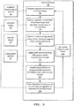
- a current region of a current near-infrared image frame contributing to a current output image is analyzed.
- the intensity value of the current region is compared to that of one or more adjacent regions. Each region can be a pixel or a group of pixels. If the intensity value of the current region is not lower than the intensity value of the adjacent region by at least the threshold amount, at step 162, then no masking is performed for this region and the next region in the current image is selected, at step 164. If the intensity value of the current region is lower than the intensity value of the adjacent region by at least the threshold amount and the current image frame 72 ( FIG.
- step 166 determines that there are other image frames to analyze for the current output frame, and step 170 select the next of such image frames.
- step 168 the process advances to the next output frame, at step 172 and a first region is selected for a first image frame of such output frame, at step 164.
- curvature correction factors can be applied to compensate for the effect of curvature.
- the processor 46 can further configured to use the near-infrared image frames to identify veins in the target tissue 24 and to omit the veins from the dynamic tissue oxygen saturation map 50.
- Measured reflectance intensities can be modified to compensate for the effect of oxygenation/deoxygenating at the veins, so as to effectively hide the veins from view and thus omit information not relevant to visualization of tissue oxygenation.
- Analysis of reflectance intensities of near-infrared image frames to detect veins can include analyzing either side of the isosbestic point.
- the feature extraction techniques previously described with respect to motion correction can be implemented to achieve vein compensation.
- the processor 46 can be configured to execute feature extraction to detect vein boundaries and interiors and to enhance vein regions for visualization.
- the processor 46 can be configured to modify the dynamic tissue oxygenation map with one or more masks determined from detected vein regions.
- the device 10 can be configured to output, via the display 48, an indication of vein contribution to the dynamic tissue oxygenation map. Such indication may include vein outlines, or similar visualization.
- the processor 46 can further be configured to perform a temporal difference operation on a sequence of frames of the dynamic tissue oxygen saturation map.
- the temporal difference operation shows oxygen saturation with respect to a reference frame of the dynamic tissue oxygen saturation map.
- a sequence of output frames 74 can be output in real time or played back from memory.
- the output frames 74 form dynamic tissue oxygen saturation map of the target tissue.
- One of such output frames 74 can be selected as a reference frame.
- a difference operation 182 can be used to subtract the reference frame 180 from subsequent output frames 74 to obtain difference frames 184.
- the difference operation 182 can be a simple difference or a higher-order difference.
- the difference frames 184 can be output in real time or played back from memory as a dynamic tissue oxygen saturation difference map. When the dynamic tissue oxygen saturation map is being recorded, different frames 184 can also be calculated as above for output frames 74 that are earlier than the reference frame 180.
- the specific reference frame 180 can be selected by the clinician, so as to observe and record changes in oxygen saturation relative to the reference without the need for a contrast agent. Such can facilitate analysis of the limits of perfusion of a perforator. For instance, the clinician first clamps/blocks the perforator of interest and waits for specified duration of time (e.g., 2 minutes) before setting the current output frame 74 as the reference frame 180. Then, the clinician releases/opens the clamped/blocked perforator.
- the difference map (before release and after release) can be used to quantify the area of the tissue being supplied by the perforator and also identify the limits of perfusion of the perforator.
- the clinician can identify the dominant perforator.
- Each of the lasers 66 is positioned to emit its laser point 190 onto the skin surface over the target tissue.
- the laser points are for assisting manual positioning of the device 10 with respect to the target tissue.
- the laser sources 66 can be arranged to provide points 190 in any suitable arrangement, such as the rectangle shown.
- the region defined by the points can be considered a region of interest 192 for multispectral imaging of tissue oxygenation. Any number of two or more laser sources 66 may be used.
- the laser sources 30 may be selected to have any suitable wavelength. If visible-light lasers are used, the visible-light image sensor 22 can capture light from the laser points reflected from the skin surface.
- the processor 46 can be further configured to include the laser points 190 in the dynamic tissue oxygen saturation map by extracting the points 190 from visible-light image frames and inserting the points 190 or representations thereof into output image frames. Visible-light lasers have the advantage of not interfering with near-infrared image processing and will not significantly affect the oxygenation map. If near-infrared lasers are used, a suitable near-infrared wavelength can be selected so that the near-infrared image sensor 20 inherently captures the points 190 as part of the image capture process. The laser points 190 are then including in the dynamic tissue oxygen saturation map without additional processing. However, it may be desirable to further configure the processor 46 to detect and ignore the laser points 190 when performing oxygenation calculations.
- the laser framing array 62 can serve to visually assist the user of the device 10 in positioning the objective lens 16 normal to the surface being imaged. In the example above, it would be expected for the points 190 to form a rectangular shape around the region of interest 192. Any skewing (e .g., the points defining a keystone or trapezoidal shape) would indicate to the clinician that the target tissue or the device 10 may need to be repositioned.
- the laser points 190 can be recorded to a captured image.
- recorded laser points 194 in a previously recorded image 196 can form an easily identified visual reference between the objective lens's view of the target and presently projected laser points 190.
- a clinician capturing a new image can manually align both anatomical features 198 (i.e., veins, hair, navel, margins) between the previously recorded image 196 and such features 200 in the new image, as well as the laser points 190 in the new image as compared to the laser points 194 in the recorded image 196.
- Manual alignment can include translating/rotating one or both of the target and the device.
- the laser sources 66 may be mounted to the housing 58 of the device 10 in the vicinity of the objective lens and generally aimed in the same direction as the principal optical axis of the objective lens.
- the processor 46 can apply a spatial transform, such as a bilinear transform, to correct the spatial difference between the two images. This can be used to correct for fine differences in normality/skew between the two images.
- Accurate alignment between stored and new images may allow for accurate comparison of precise localized changes in tissue oxygenation. This can allow clinicians to improve care and/or initiate interventions.
- FIG. 14 illustrates another laser framing array 204 suitable for use as the laser framing array 62.
- Line generating optics 206 may be provided to emit lines 208 of laser light onto the skin surface over the target tissue.
- the lines 208 of laser light include the laser points 190 previously discussed, and the same general principles apply. The above description may be referenced.
- the lasers 66 and optics 206 may be arranged so that the lines form a rectangular box or other shape that bounds the region of interest 192.
- One advantage of laser lines is that operators may find them more visible, and therefore the device 10 may be more convenient to use.
- FIG. 15 shows an example of the laser positioning array 60 configured to assist in positioning the device 10 at a target distance from the target tissue, the target distance being, for instance, a suitable focal distance of the objective lens.
- An example target distance is about 610 mm.
- a first positioning laser 64 is positioned at a first offset distance from the optical axis 210 of the objective lens 16 and is aimed at a first angle 212 with respect to the optical axis 210.
- the first positioning laser 64 is aimed to emit, as shown in FIG. 16A , a first positioning laser spot 214 on a skin surface 216 over the target tissue.
- the first positioning laser 64 is affixed to the housing 58 or other component of the multispectral medical imaging device 10. Hence, as the device 10 is moved towards and away from the surface 216, the first positioning laser spot 214 traverses along a first path 218.
- a second positioning laser 64 is positioned at a second offset distance from the optical axis 210 of the objective lens 16 and is aimed at a second angle 220 with respect to the optical axis 210.
- the second positioning laser 64 is aimed to emit, as shown in FIG. 16A , a second positioning laser spot 222 on a skin surface 216.
- the second positioning laser 64 is affixed to the housing 58 or other component of the device 10. Hence, as the device 10 is moved towards and away from the surface 216, the second positioning laser spot 222 traverses along a second path 224.
- the first and second angles 212, 220 lay in different planes that each contains the optical axis 210.
- the optical axis 210 can be considered the intersection of these planes. That is, the first and second positioning lasers 64 are each laterally offset from the optical axis 210 and are also angularly offset from each other. If the first positioning laser 64 is at a position of 0 degrees on a circle centered at the optical axis, the second positioning laser 64 is at a different angle, such as 90 degrees. In this example, the first and second positioning lasers 64 are positioned at about 90 degrees apart.
- the first and second offset distances and the first and second angles 212, 220 are selected to cause the first positioning laser spot 214 and the second positioning laser spot 222 to be coincident at the optical axis when the target tissue is a target distance from the objective lens 16. This is shown in FIG. 16C .
- the first and second offset distances and the first and second angles 212, 220 can be selected to position the first and second positioning laser spots 214, 222 on one side 230 of the optical axis 210 of the objective lens 16 when a distance from the objective lens to the surface 216 of the target tissue is greater than the target distance ( FIG. 16A ). Conversely, when the distance from the objective lens to the target tissue is less than the target distance, the first and second positioning laser spots 214, 222 appear on an opposite side 232 ( FIG. 16B ).
- the two positioning spots 214, 222 move along their respective paths 218, 224.
- the positioning spots 214, 222 appear as separate spots on one side 232 of the target surface 216 if the device 10 and target tissue are too close, as shown in FIG. 16B .
- the positioning spots 214, 222 appear as separate spots on an opposite side 230 of the target surface 216 if the device 10 and target tissue are too far, as shown in FIG. 16A . Adjusting the distance of the device 10 to the target tissue in a direction that causes the spots to diverge indicates to the clinician that the adjustment is opposite to what is required.
- Adjusting the distance of the device 10 to the target tissue in a direction that causes the spots 214, 222 to converge indicates to the clinician that the adjustment is in the correct direction, until the spots 214, 222 become coincident thereby indicating that the target distance has been reached, as shown in FIG. 16C .
- the visible-light image sensor 22 and the processor 46 can be configured to capture and monitor the positions of spots 214, 222 and output, via the display 48 or an component of the user interface 52, such as a speaker, an indication to the user as to the positions of the spots 214, 222 and/or the direction in which to move the device 10 to arrive at the target distance.
- Such indications can be of the form of raw distance information, visible or audible warnings (e.g., "Target too close", “Target too far”), or similar.
- the processor 46 can be configured to automatically turn off the lasers 64 when oxygen saturation image capture starts.
- the multispectral medical imaging device 10 is capable of assisting in determining a venous block and a venous and arterial block.
- FIG. 17 shows a chart of rates of desaturation of hemoglobin, as calculated by device 10, for a simulated venous block and a simulated venous and arterial block.
- the x-axis is sample points, representative of time, and the y-axis is oxygen saturation percentage.
- a venous block exhibits a slower rate of oxygen desaturation, whereas a venous and arterial block exhibits a higher rate of desaturation.
- the venous block also does not reach as low a level of oxygen saturation as does the venous and arterial block.
- the device 10 can be configured with a selectable threshold level 250 to assist in differentiating between a venous block and a venous and arterial block. Additionally or alternatively, the device 10 can be configured to calculate and selectably output a chart of oxygen saturation over time, similar to shown, for the target tissue 24 as a whole, to permit a clinician to view such and compare such to a selectable threshold level 250, if provided. One or more reference slopes 252 may also be provided to assist the clinician in assessing desaturation rate.
- the device 10 can be configured to provide for selection of a block test duration, such as 45 seconds, 1 minute, etc.
- the multispectral medical imaging device 10 is capable of detecting water content in the target tissue.
- the device may thus also be configured to detect a venous block by detecting increased water retention caused by a venous block in the region of interest.
- Video frame rates can be achieved without moving parts. Compensation is provided for ambient lighting, patient skin tone, curvature, and the presence of vasculature.
- the invention also provides for aiming the device at the correct focal distance and towards an area of interest, in a convenient and repeatable manner.
- useful supplemental features such as temporal difference visualization of oxygen desaturation and venous/arterial block detection, are provided.
Landscapes
- Health & Medical Sciences (AREA)
- Life Sciences & Earth Sciences (AREA)
- Physics & Mathematics (AREA)
- Engineering & Computer Science (AREA)
- Veterinary Medicine (AREA)
- Pathology (AREA)
- Biomedical Technology (AREA)
- Heart & Thoracic Surgery (AREA)
- Medical Informatics (AREA)
- Molecular Biology (AREA)
- Surgery (AREA)
- Animal Behavior & Ethology (AREA)
- General Health & Medical Sciences (AREA)
- Public Health (AREA)
- Biophysics (AREA)
- Physiology (AREA)
- Signal Processing (AREA)
- Optics & Photonics (AREA)
- Cardiology (AREA)
- Spectroscopy & Molecular Physics (AREA)
- Vascular Medicine (AREA)
- Artificial Intelligence (AREA)
- Computer Vision & Pattern Recognition (AREA)
- Psychiatry (AREA)
- Hematology (AREA)
- Measurement Of The Respiration, Hearing Ability, Form, And Blood Characteristics Of Living Organisms (AREA)
- Investigating Or Analysing Materials By Optical Means (AREA)
- Measuring Pulse, Heart Rate, Blood Pressure Or Blood Flow (AREA)
- Length Measuring Devices By Optical Means (AREA)
Applications Claiming Priority (2)
| Application Number | Priority Date | Filing Date | Title |
|---|---|---|---|
| US14/341,103 US9968285B2 (en) | 2014-07-25 | 2014-07-25 | Multispectral medical imaging devices and methods thereof |
| EP15178385.9A EP2977003B1 (de) | 2014-07-25 | 2015-07-24 | Multispektrale medizinische bilderzeugungsvorrichtungen und verfahren dafür |
Related Parent Applications (2)
| Application Number | Title | Priority Date | Filing Date |
|---|---|---|---|
| EP15178385.9A Division EP2977003B1 (de) | 2014-07-25 | 2015-07-24 | Multispektrale medizinische bilderzeugungsvorrichtungen und verfahren dafür |
| EP15178385.9A Division-Into EP2977003B1 (de) | 2014-07-25 | 2015-07-24 | Multispektrale medizinische bilderzeugungsvorrichtungen und verfahren dafür |
Publications (1)
| Publication Number | Publication Date |
|---|---|
| EP3545839A1 true EP3545839A1 (de) | 2019-10-02 |
Family
ID=54105599
Family Applications (2)
| Application Number | Title | Priority Date | Filing Date |
|---|---|---|---|
| EP15178385.9A Active EP2977003B1 (de) | 2014-07-25 | 2015-07-24 | Multispektrale medizinische bilderzeugungsvorrichtungen und verfahren dafür |
| EP19175580.0A Withdrawn EP3545839A1 (de) | 2014-07-25 | 2015-07-24 | Multispektrale medizinische bilderzeugungsvorrichtungen und verfahren dafür |
Family Applications Before (1)
| Application Number | Title | Priority Date | Filing Date |
|---|---|---|---|
| EP15178385.9A Active EP2977003B1 (de) | 2014-07-25 | 2015-07-24 | Multispektrale medizinische bilderzeugungsvorrichtungen und verfahren dafür |
Country Status (4)
| Country | Link |
|---|---|
| US (2) | US9968285B2 (de) |
| EP (2) | EP2977003B1 (de) |
| JP (2) | JP2016030214A (de) |
| CN (2) | CN105286785B (de) |
Families Citing this family (58)
| Publication number | Priority date | Publication date | Assignee | Title |
|---|---|---|---|---|
| US9071740B1 (en) | 2011-10-28 | 2015-06-30 | Google Inc. | Modular camera system |
| US9197686B1 (en) | 2012-01-06 | 2015-11-24 | Google Inc. | Backfill of video stream |
| US9537968B1 (en) | 2012-01-06 | 2017-01-03 | Google Inc. | Communication of socket protocol based data over a storage protocol based interface |
| DK3297528T3 (da) * | 2015-05-20 | 2020-11-16 | Kent Imaging | Automatisk kompensering for lyssvækkelsen på grund af epidermisk melanin i hudbilleder |
| US9544485B2 (en) | 2015-05-27 | 2017-01-10 | Google Inc. | Multi-mode LED illumination system |
| US9886620B2 (en) | 2015-06-12 | 2018-02-06 | Google Llc | Using a scene illuminating infrared emitter array in a video monitoring camera to estimate the position of the camera |
| US9489745B1 (en) | 2015-06-12 | 2016-11-08 | Google Inc. | Using depth maps of a scene to identify movement of a video camera |
| US9454820B1 (en) | 2015-06-12 | 2016-09-27 | Google Inc. | Using a scene illuminating infrared emitter array in a video monitoring camera for depth determination |
| US9626849B2 (en) | 2015-06-12 | 2017-04-18 | Google Inc. | Using scene information from a security camera to reduce false security alerts |
| US9235899B1 (en) | 2015-06-12 | 2016-01-12 | Google Inc. | Simulating an infrared emitter array in a video monitoring camera to construct a lookup table for depth determination |
| US9386230B1 (en) | 2015-06-12 | 2016-07-05 | Google Inc. | Day and night detection based on one or more of illuminant detection, lux level detection, and tiling |
| US9554063B2 (en) | 2015-06-12 | 2017-01-24 | Google Inc. | Using infrared images of a monitored scene to identify windows |
| US9613423B2 (en) | 2015-06-12 | 2017-04-04 | Google Inc. | Using a depth map of a monitored scene to identify floors, walls, and ceilings |
| CA2942773C (en) * | 2015-09-25 | 2023-06-27 | Smart Technologies Ulc | System and method of pointer detection for interactive input |
| TWI765885B (zh) | 2016-04-21 | 2022-06-01 | 美商菲歐普提斯公司 | 利用黑色素校正之測定組織氧飽和度的方法和裝置 |
| FR3051341B1 (fr) * | 2016-05-18 | 2018-06-01 | Universite De Lorraine | Dispositif medical sans fil d'acquisition de videos cutanees bimodalite avec controle lumineux |
| CN114795151A (zh) | 2016-06-30 | 2022-07-29 | 松下知识产权经营株式会社 | 方法及系统 |
| CN106264467B (zh) * | 2016-08-10 | 2023-05-23 | 河南埃尔森智能科技有限公司 | 一种多功能双红外血管显像仪及其显像方法 |
| CN106236016B (zh) * | 2016-08-18 | 2019-02-26 | 皖江新兴产业技术发展中心 | 一种用于静脉显像的原位投影方法 |
| CA3034761A1 (en) | 2016-08-24 | 2018-03-01 | Mimosa Diagnostics Inc. | Multispectral mobile tissue assessment |
| TW201816718A (zh) * | 2016-10-20 | 2018-05-01 | 華碩電腦股份有限公司 | 影像處理系統與影像處理方法 |
| US10180615B2 (en) | 2016-10-31 | 2019-01-15 | Google Llc | Electrochromic filtering in a camera |
| CN116269261B (zh) | 2016-12-01 | 2025-10-28 | 松下知识产权经营株式会社 | 生物体信息处理方法及生物体信息处理系统 |
| JP7069166B2 (ja) * | 2016-12-08 | 2022-05-17 | コーニンクレッカ フィリップス エヌ ヴェ | 表面組織追跡 |
| GB2557928A (en) * | 2016-12-16 | 2018-07-04 | Fuel 3D Tech Limited | Systems and methods for obtaining data characterizing a three-dimensional object |
| WO2018117912A1 (ru) * | 2016-12-23 | 2018-06-28 | Общество С Ограниченной Ответственностью "Научно-Исследовательский Центр "Прософт-Системы" | Устройство захвата изображения вен ладони |
| CN106779042B (zh) * | 2016-12-27 | 2023-08-04 | 北京农业信息技术研究中心 | 一种水产养殖鱼群聚集指数计算装置及计算方法 |
| CN107049254A (zh) * | 2017-04-05 | 2017-08-18 | 展谱光电科技(上海)有限公司 | 便携式多光谱摄像和投影装置及方法 |
| JP6923129B2 (ja) * | 2017-06-26 | 2021-08-18 | タカノ株式会社 | 情報処理装置、プログラム、方法及びシステム |
| CA3064779A1 (en) | 2017-09-15 | 2019-03-21 | Kent Imaging | Hybrid visible and near infrared imaging with an rgb color filter array sensor |
| JP6766021B2 (ja) * | 2017-09-20 | 2020-10-07 | H2L株式会社 | 生体情報測定器 |
| WO2019165480A1 (en) * | 2018-02-26 | 2019-08-29 | Caliber Imaging & Diagnostics, Inc. | System and method for macroscopic and microscopic imaging ex-vivo tissue |
| JP2021526907A (ja) | 2018-06-08 | 2021-10-11 | イースト カロライナ ユニバーシティ | マルチスペクトルレーザ撮像(MSLI)方法及びシステムを使用した末梢血酸素飽和度(SpO2)及びヘモグロビン濃度の決定 |
| CN108968942A (zh) * | 2018-08-03 | 2018-12-11 | 佛山科学技术学院 | 一种基于近红外全色彩血流成像装置及方法 |
| WO2020081159A2 (en) | 2018-09-05 | 2020-04-23 | East Carolina University | Systems for detecting vascular and arterial disease in asymptomatic patients and related methods |
| JP7386438B2 (ja) * | 2018-12-20 | 2023-11-27 | パナソニックIpマネジメント株式会社 | 生体計測装置、生体計測方法、コンピュータ読み取り可能な記録媒体、およびプログラム |
| JP7648525B2 (ja) | 2019-01-17 | 2025-03-18 | モレキュライト・インコーポレイテッド | マルチモーダル撮像および解析のためのモジュールシステム |
| CA3127048A1 (en) | 2019-01-17 | 2020-07-23 | Sbi Alapharma Canada, Inc. | Devices, systems, and methods for tumor visualization and removal |
| WO2020163286A1 (en) | 2019-02-04 | 2020-08-13 | Massachusetts Institute Of Technology | Systems and methods for lymph nodes and vessels imaging |
| US20200294228A1 (en) * | 2019-03-13 | 2020-09-17 | East Carolina University | Non-Contact Multispectral Imaging for Blood Oxygen Level and Perfusion Measurement and Related Systems and Computer Program Products |
| CA3134066A1 (en) | 2019-03-26 | 2020-10-01 | East Carolina University | Near-infrared fluorescence imaging for blood flow and perfusion visualization and related systems and computer program products |
| EP3725257A1 (de) * | 2019-04-16 | 2020-10-21 | Koninklijke Philips N.V. | Lichtbetriebener, lichtemittierender gewebemarker |
| US11478145B2 (en) | 2019-05-15 | 2022-10-25 | Aizhong Zhang | Multispectral and hyperspectral meibography |
| CN110292373A (zh) * | 2019-07-23 | 2019-10-01 | 优谱激光科技(南京)有限公司 | 一种高性能人体组织血流检测分析装置 |
| US11253151B2 (en) | 2019-09-08 | 2022-02-22 | Aizhong Zhang | Multispectral and hyperspectral ocular surface evaluator |
| FR3104873B1 (fr) * | 2019-12-16 | 2023-05-26 | Tangram Image Sensor | Terminal communiquant avec imageur perfectionné |
| CN111991004A (zh) * | 2020-08-20 | 2020-11-27 | 广州医软智能科技有限公司 | 血氧饱和度测量设备、测量方法和测量装置 |
| US11359965B2 (en) | 2020-10-05 | 2022-06-14 | Samsung Electronics Co., Ltd. | Apparatus and method for estimating target component |
| US12042280B2 (en) | 2021-01-25 | 2024-07-23 | Samsung Electronics Co., Ltd. | Apparatus and method for estimating oxygen saturation |
| JP7152727B2 (ja) * | 2021-02-25 | 2022-10-13 | エバ・ジャパン 株式会社 | 生体情報算出装置及び生体情報算出方法 |
| USD1117133S1 (en) | 2021-08-23 | 2026-03-10 | Moleculight Inc. | Modular handheld imaging device |
| EP4162862A1 (de) * | 2021-10-07 | 2023-04-12 | Koninklijke Philips N.V. | Verfahren und vorrichtung zur analyse von bildern von haar und haut auf einem körper eines patienten |
| EP4210324A1 (de) | 2022-01-11 | 2023-07-12 | Koninklijke Philips N.V. | Verfahren und vorrichtung zum ausrichten von bildern in einer sequenz von bildrahmen |
| WO2023164759A1 (en) | 2022-03-01 | 2023-09-07 | Mimosa Diagnostics Inc. | Releasable portable imaging device for multispectral moblie tissue assessment |
| US20260026718A1 (en) * | 2022-08-03 | 2026-01-29 | The University Of North Carolina At Chapel Hill | Methods, systems, and computer readable media for melanin-concentration-adjusted pulse oximetry |
| US12219226B2 (en) * | 2022-09-19 | 2025-02-04 | Apple Inc. | Shared aperture imaging system for acquiring visible and infrared images |
| US12266984B2 (en) | 2022-09-22 | 2025-04-01 | Apple Inc. | Compact multilayer actuator coils for camera modules of portable electronic devices |
| US12335591B2 (en) | 2022-09-23 | 2025-06-17 | Apple Inc. | Camera module substrate designs |
Citations (8)
| Publication number | Priority date | Publication date | Assignee | Title |
|---|---|---|---|---|
| US5620436A (en) * | 1994-09-22 | 1997-04-15 | Chiron Technolas Gmbh Ophthalmologische Systeme | Method and apparatus for providing precise location of points on the eye |
| US20070024946A1 (en) * | 2004-12-28 | 2007-02-01 | Panasyuk Svetlana V | Hyperspectral/multispectral imaging in determination, assessment and monitoring of systemic physiology and shock |
| US20090245601A1 (en) * | 2008-03-31 | 2009-10-01 | Immersion Corporation | Locating Blood Vessels |
| US20120071765A1 (en) * | 2010-09-17 | 2012-03-22 | Optimum Technologies, Inc. | Digital Mapping System and Method |
| US20120083772A1 (en) * | 2010-09-30 | 2012-04-05 | Curveright Llc | Corneal treatment system and method |
| US20120277559A1 (en) * | 2009-12-08 | 2012-11-01 | Matthias Kohl-Bareis | Apparatus for Measuring Blood Parameters |
| US8644911B1 (en) * | 2006-06-30 | 2014-02-04 | Hypermed Imaging, Inc. | OxyVu-1 hyperspectral tissue oxygenation (HTO) measurement system |
| US20140187968A1 (en) * | 2012-12-27 | 2014-07-03 | Christie Digital Systems Canada Inc. | Spectral imaging with a color wheel |
Family Cites Families (41)
| Publication number | Priority date | Publication date | Assignee | Title |
|---|---|---|---|---|
| US4426726A (en) | 1982-02-23 | 1984-01-17 | Cheetham Eric C | Apparatus and method for X-ray beam alignment |
| US4836671A (en) * | 1985-04-08 | 1989-06-06 | Charles Lescrenier | Locating device |
| US6985172B1 (en) * | 1995-12-01 | 2006-01-10 | Southwest Research Institute | Model-based incident detection system with motion classification |
| US6937885B1 (en) | 1997-10-30 | 2005-08-30 | Hypermed, Inc. | Multispectral/hyperspectral medical instrument |
| US6021210A (en) * | 1997-12-01 | 2000-02-01 | Sensar, Inc. | Image subtraction to remove ambient illumination |
| US6503195B1 (en) | 1999-05-24 | 2003-01-07 | University Of North Carolina At Chapel Hill | Methods and systems for real-time structured light depth extraction and endoscope using real-time structured light depth extraction |
| WO2001001854A2 (en) * | 1999-07-02 | 2001-01-11 | Hypermed Imaging, Inc. | Integrated imaging apparatus |
| US6640132B1 (en) | 1999-11-17 | 2003-10-28 | Hypermed, Inc. | Forensic hyperspectral apparatus and method |
| US6826424B1 (en) | 2000-12-19 | 2004-11-30 | Haishan Zeng | Methods and apparatus for fluorescence and reflectance imaging and spectroscopy and for contemporaneous measurements of electromagnetic radiation with multiple measuring devices |
| CN100571611C (zh) * | 2002-04-02 | 2009-12-23 | 耶德研究和发展有限公司 | 固定背景中的移动物体的特征描述 |
| US20050049467A1 (en) * | 2003-08-28 | 2005-03-03 | Georgios Stamatas | Method for assessing pigmented skin |
| US8224425B2 (en) | 2005-04-04 | 2012-07-17 | Hypermed Imaging, Inc. | Hyperspectral imaging in diabetes and peripheral vascular disease |
| US7147371B2 (en) | 2004-12-10 | 2006-12-12 | Joseph Hecker | Laser guides for X-ray device |
| US20060241495A1 (en) * | 2005-03-23 | 2006-10-26 | Eastman Kodak Company | Wound healing monitoring and treatment |
| EP1880165A2 (de) | 2005-03-24 | 2008-01-23 | Infotonics Technology Center, Inc. | Hyperspektrales bildgebungssystem und verfahren dafür |
| CA2947613C (en) * | 2005-04-04 | 2019-11-05 | Hypermed Imaging, Inc. | Hyperspectral imaging in diabetes and peripheral vascular disease |
| WO2006124696A1 (en) | 2005-05-13 | 2006-11-23 | Children's Hospital Medical Center | Multi-wavelength spatial domain near infrared oximeter to detect cerebral hypoxia-ischemia |
| US7342658B2 (en) | 2005-12-28 | 2008-03-11 | Eastman Kodak Company | Programmable spectral imaging system |
| US7460248B2 (en) | 2006-05-15 | 2008-12-02 | Carestream Health, Inc. | Tissue imaging system |
| MX2009008653A (es) * | 2007-02-14 | 2009-12-08 | Luminetx Corp | Sistema y metodo para proyeccion de estructura de subsuperficie sobre una superficie de un objeto. |
| US8004502B2 (en) | 2007-10-05 | 2011-08-23 | Microsoft Corporation | Correcting for ambient light in an optical touch-sensitive device |
| WO2009117603A2 (en) | 2008-03-19 | 2009-09-24 | Hypermed, Inc. | Miniaturized multi-spectral imager for real-time tissue oxygenation measurement |
| US9883833B2 (en) | 2008-05-13 | 2018-02-06 | Spectral Image, Inc. | Systems and methods for hyperspectral medical imaging using real-time projection of spectral information |
| EP2297696B1 (de) | 2008-06-30 | 2014-02-26 | Koninklijke Philips N.V. | Perfusionsbildgebung |
| US7791008B2 (en) | 2008-07-31 | 2010-09-07 | John Taylor Hargrove | Single spot focus control |
| US8406859B2 (en) | 2008-08-10 | 2013-03-26 | Board Of Regents, The University Of Texas System | Digital light processing hyperspectral imaging apparatus |
| EP2208460A1 (de) * | 2009-01-19 | 2010-07-21 | BrainLAB AG | Erkennung und Lokalisierung von Gewebe durch Lichtanalyse |
| US8289300B2 (en) | 2009-07-17 | 2012-10-16 | Microsoft Corporation | Ambient correction in rolling image capture system |
| WO2011017550A2 (en) * | 2009-08-05 | 2011-02-10 | The Johns Hopkins University | Programmable multispectral illumination system for surgery and visualization of light-sensitive tissues |
| AU2011229113A1 (en) * | 2010-03-17 | 2012-10-18 | Yasser Fawzy | Rapid multi-spectral imaging methods and apparatus and applications for cancer detection and localization |
| US8371751B2 (en) * | 2010-06-29 | 2013-02-12 | David Vazquez | Laser guided patient positioning system for chiropractic x-rays and method of use |
| US8743201B2 (en) | 2010-09-27 | 2014-06-03 | National Applied Research Laboratories | Time-Sequential multi-spectrum imaging device |
| CN202078301U (zh) | 2011-05-17 | 2011-12-21 | 易定容 | 血管找寻器 |
| US9692991B2 (en) * | 2011-11-04 | 2017-06-27 | Qualcomm Incorporated | Multispectral imaging system |
| HK1202402A1 (en) | 2012-05-03 | 2015-10-02 | Vioptix, Inc. | Tissue oximetry probe geometry for robust calibration and self-correction |
| US8897522B2 (en) * | 2012-05-30 | 2014-11-25 | Xerox Corporation | Processing a video for vascular pattern detection and cardiac function analysis |
| JP6023883B2 (ja) * | 2012-07-10 | 2016-11-09 | アイマゴ ソシエテ アノニムAimago S.A. | 灌流評価マルチモダリティ光学医用デバイス |
| WO2014012946A1 (en) * | 2012-07-16 | 2014-01-23 | Flir Systems Ab | Correction of image distortion in ir imaging |
| US9398287B2 (en) * | 2013-02-28 | 2016-07-19 | Google Technology Holdings LLC | Context-based depth sensor control |
| US9125606B2 (en) * | 2013-03-13 | 2015-09-08 | Koninklijke Philips N.V. | Device and method for determining the blood oxygen saturation of a subject |
| CN103505182B (zh) | 2013-09-17 | 2015-07-08 | 周红仙 | 一种手持式成像系统的定位装置及定位方法 |
-
2014
- 2014-07-25 US US14/341,103 patent/US9968285B2/en not_active Expired - Fee Related
-
2015
- 2015-07-10 JP JP2015138296A patent/JP2016030214A/ja not_active Ceased
- 2015-07-24 EP EP15178385.9A patent/EP2977003B1/de active Active
- 2015-07-24 EP EP19175580.0A patent/EP3545839A1/de not_active Withdrawn
- 2015-07-27 CN CN201510446731.3A patent/CN105286785B/zh not_active Expired - Fee Related
- 2015-07-27 CN CN201810939646.4A patent/CN109008985A/zh not_active Withdrawn
-
2018
- 2018-01-03 US US15/861,521 patent/US20180160953A1/en not_active Abandoned
-
2019
- 2019-09-04 JP JP2019161343A patent/JP2020011079A/ja not_active Ceased
Patent Citations (8)
| Publication number | Priority date | Publication date | Assignee | Title |
|---|---|---|---|---|
| US5620436A (en) * | 1994-09-22 | 1997-04-15 | Chiron Technolas Gmbh Ophthalmologische Systeme | Method and apparatus for providing precise location of points on the eye |
| US20070024946A1 (en) * | 2004-12-28 | 2007-02-01 | Panasyuk Svetlana V | Hyperspectral/multispectral imaging in determination, assessment and monitoring of systemic physiology and shock |
| US8644911B1 (en) * | 2006-06-30 | 2014-02-04 | Hypermed Imaging, Inc. | OxyVu-1 hyperspectral tissue oxygenation (HTO) measurement system |
| US20090245601A1 (en) * | 2008-03-31 | 2009-10-01 | Immersion Corporation | Locating Blood Vessels |
| US20120277559A1 (en) * | 2009-12-08 | 2012-11-01 | Matthias Kohl-Bareis | Apparatus for Measuring Blood Parameters |
| US20120071765A1 (en) * | 2010-09-17 | 2012-03-22 | Optimum Technologies, Inc. | Digital Mapping System and Method |
| US20120083772A1 (en) * | 2010-09-30 | 2012-04-05 | Curveright Llc | Corneal treatment system and method |
| US20140187968A1 (en) * | 2012-12-27 | 2014-07-03 | Christie Digital Systems Canada Inc. | Spectral imaging with a color wheel |
Also Published As
| Publication number | Publication date |
|---|---|
| US20180160953A1 (en) | 2018-06-14 |
| CN105286785A (zh) | 2016-02-03 |
| US9968285B2 (en) | 2018-05-15 |
| CN109008985A (zh) | 2018-12-18 |
| EP2977003A1 (de) | 2016-01-27 |
| HK1215142A1 (zh) | 2016-08-19 |
| JP2020011079A (ja) | 2020-01-23 |
| CN105286785B (zh) | 2018-09-18 |
| EP2977003B1 (de) | 2020-03-04 |
| US20160022181A1 (en) | 2016-01-28 |
| JP2016030214A (ja) | 2016-03-07 |
Similar Documents
| Publication | Publication Date | Title |
|---|---|---|
| EP2977003B1 (de) | Multispektrale medizinische bilderzeugungsvorrichtungen und verfahren dafür | |
| US12029385B2 (en) | Electronic endoscope system | |
| US11026763B2 (en) | Projection mapping apparatus | |
| JP6763719B2 (ja) | 生体情報測定装置、生体情報測定方法及びプログラム | |
| US10517472B2 (en) | Endoscope system | |
| EP3427633A1 (de) | Blutgefässinformationserfassungsvorrichtung, endoskopsystem und blutgefässinformationserfassungsverfahren | |
| RU2580788C2 (ru) | Устройство для сканирования штрихкода для определения физиологического параметра пациента | |
| US11944261B2 (en) | Electronic endoscope system and data processing device | |
| US10736499B2 (en) | Image analysis apparatus, image analysis system, and method for operating image analysis apparatus | |
| EP3391806B1 (de) | Endoskopsystem, prozessorvorrichtung und endoskopsystembetriebsverfahren | |
| US20170164844A1 (en) | Information obtaining apparatus, image capturing apparatus, and method for obtaining information | |
| DK3051490T3 (en) | Ophthalmological device, method of imaging and program | |
| US20210338043A1 (en) | Electronic endoscope system and data processing device | |
| WO2017154325A1 (ja) | 内視鏡システム、プロセッサ装置、及び、内視鏡システムの作動方法 | |
| CN112469323A (zh) | 内窥镜系统 | |
| US20220192470A1 (en) | Endoscope system | |
| JP2017153748A (ja) | 光断層像撮影装置 | |
| JPWO2018159082A1 (ja) | 内視鏡システム、プロセッサ装置、及び、内視鏡システムの作動方法 | |
| CN109414120B (zh) | 用于提供语义信息的装置以及操作其的方法 | |
| WO2019146582A1 (ja) | 撮像装置、撮像システム、及び撮像方法 | |
| HK1261447A1 (en) | Multispectral medical imaging devices and methods thereof | |
| HK1215142B (en) | Multispectral medical imaging devices and methods thereof | |
| JPWO2013133341A1 (ja) | 光学測定装置 | |
| WO2018216658A1 (ja) | 撮像装置、撮像システム、及び撮像方法 | |
| KR101559253B1 (ko) | 조명을 이용한 설 촬영 장치 및 방법 |
Legal Events
| Date | Code | Title | Description |
|---|---|---|---|
| PUAI | Public reference made under article 153(3) epc to a published international application that has entered the european phase |
Free format text: ORIGINAL CODE: 0009012 |
|
| STAA | Information on the status of an ep patent application or granted ep patent |
Free format text: STATUS: THE APPLICATION HAS BEEN PUBLISHED |
|
| STAA | Information on the status of an ep patent application or granted ep patent |
Free format text: STATUS: REQUEST FOR EXAMINATION WAS MADE |
|
| AC | Divisional application: reference to earlier application |
Ref document number: 2977003 Country of ref document: EP Kind code of ref document: P |
|
| AK | Designated contracting states |
Kind code of ref document: A1 Designated state(s): AL AT BE BG CH CY CZ DE DK EE ES FI FR GB GR HR HU IE IS IT LI LT LU LV MC MK MT NL NO PL PT RO RS SE SI SK SM TR |
|
| 17P | Request for examination filed |
Effective date: 20190913 |
|
| RBV | Designated contracting states (corrected) |
Designated state(s): AL AT BE BG CH CY CZ DE DK EE ES FI FR GB GR HR HU IE IS IT LI LT LU LV MC MK MT NL NO PL PT RO RS SE SI SK SM TR |
|
| STAA | Information on the status of an ep patent application or granted ep patent |
Free format text: STATUS: EXAMINATION IS IN PROGRESS |
|
| 17Q | First examination report despatched |
Effective date: 20210816 |
|
| STAA | Information on the status of an ep patent application or granted ep patent |
Free format text: STATUS: THE APPLICATION IS DEEMED TO BE WITHDRAWN |
|
| 18D | Application deemed to be withdrawn |
Effective date: 20220104 |