EP3545596B1 - Cover assemblies for cables and electrical connections and pre-expanded units and methods including same - Google Patents
Cover assemblies for cables and electrical connections and pre-expanded units and methods including same Download PDFInfo
- Publication number
- EP3545596B1 EP3545596B1 EP17812166.1A EP17812166A EP3545596B1 EP 3545596 B1 EP3545596 B1 EP 3545596B1 EP 17812166 A EP17812166 A EP 17812166A EP 3545596 B1 EP3545596 B1 EP 3545596B1
- Authority
- EP
- European Patent Office
- Prior art keywords
- outer sleeve
- cover assembly
- layer
- sleeve
- section
- Prior art date
- Legal status (The legal status is an assumption and is not a legal conclusion. Google has not performed a legal analysis and makes no representation as to the accuracy of the status listed.)
- Active
Links
Images


Classifications
-
- H—ELECTRICITY
- H02—GENERATION; CONVERSION OR DISTRIBUTION OF ELECTRIC POWER
- H02G—INSTALLATION OF ELECTRIC CABLES OR LINES, OR OF COMBINED OPTICAL AND ELECTRIC CABLES OR LINES
- H02G15/00—Cable fittings
- H02G15/08—Cable junctions
- H02G15/18—Cable junctions protected by sleeves, e.g. for communication cable
-
- H—ELECTRICITY
- H01—ELECTRIC ELEMENTS
- H01B—CABLES; CONDUCTORS; INSULATORS; SELECTION OF MATERIALS FOR THEIR CONDUCTIVE, INSULATING OR DIELECTRIC PROPERTIES
- H01B3/00—Insulators or insulating bodies characterised by the insulating materials; Selection of materials for their insulating or dielectric properties
- H01B3/18—Insulators or insulating bodies characterised by the insulating materials; Selection of materials for their insulating or dielectric properties mainly consisting of organic substances
- H01B3/30—Insulators or insulating bodies characterised by the insulating materials; Selection of materials for their insulating or dielectric properties mainly consisting of organic substances plastics; resins; waxes
- H01B3/44—Insulators or insulating bodies characterised by the insulating materials; Selection of materials for their insulating or dielectric properties mainly consisting of organic substances plastics; resins; waxes vinyl resins; acrylic resins
- H01B3/441—Insulators or insulating bodies characterised by the insulating materials; Selection of materials for their insulating or dielectric properties mainly consisting of organic substances plastics; resins; waxes vinyl resins; acrylic resins from alkenes
-
- H—ELECTRICITY
- H02—GENERATION; CONVERSION OR DISTRIBUTION OF ELECTRIC POWER
- H02G—INSTALLATION OF ELECTRIC CABLES OR LINES, OR OF COMBINED OPTICAL AND ELECTRIC CABLES OR LINES
- H02G1/00—Methods or apparatus specially adapted for installing, maintaining, repairing or dismantling electric cables or lines
- H02G1/14—Methods or apparatus specially adapted for installing, maintaining, repairing or dismantling electric cables or lines for joining or terminating cables
-
- H—ELECTRICITY
- H02—GENERATION; CONVERSION OR DISTRIBUTION OF ELECTRIC POWER
- H02G—INSTALLATION OF ELECTRIC CABLES OR LINES, OR OF COMBINED OPTICAL AND ELECTRIC CABLES OR LINES
- H02G15/00—Cable fittings
- H02G15/08—Cable junctions
- H02G15/18—Cable junctions protected by sleeves, e.g. for communication cable
- H02G15/182—Cable junctions protected by sleeves, e.g. for communication cable held in expanded condition in radial direction prior to installation
- H02G15/1826—Cable junctions protected by sleeves, e.g. for communication cable held in expanded condition in radial direction prior to installation on a removable hollow core, e.g. a tube
-
- H—ELECTRICITY
- H02—GENERATION; CONVERSION OR DISTRIBUTION OF ELECTRIC POWER
- H02G—INSTALLATION OF ELECTRIC CABLES OR LINES, OR OF COMBINED OPTICAL AND ELECTRIC CABLES OR LINES
- H02G15/00—Cable fittings
- H02G15/02—Cable terminations
- H02G15/06—Cable terminating boxes, frames or other structures
- H02G15/064—Cable terminating boxes, frames or other structures with devices for relieving electrical stress
-
- H—ELECTRICITY
- H02—GENERATION; CONVERSION OR DISTRIBUTION OF ELECTRIC POWER
- H02G—INSTALLATION OF ELECTRIC CABLES OR LINES, OR OF COMBINED OPTICAL AND ELECTRIC CABLES OR LINES
- H02G15/00—Cable fittings
- H02G15/08—Cable junctions
- H02G15/18—Cable junctions protected by sleeves, e.g. for communication cable
- H02G15/182—Cable junctions protected by sleeves, e.g. for communication cable held in expanded condition in radial direction prior to installation
- H02G15/1826—Cable junctions protected by sleeves, e.g. for communication cable held in expanded condition in radial direction prior to installation on a removable hollow core, e.g. a tube
- H02G15/1833—Cable junctions protected by sleeves, e.g. for communication cable held in expanded condition in radial direction prior to installation on a removable hollow core, e.g. a tube formed of helically wound strip with adjacent windings, which are removable by applying a pulling force to a strip end
-
- H—ELECTRICITY
- H02—GENERATION; CONVERSION OR DISTRIBUTION OF ELECTRIC POWER
- H02G—INSTALLATION OF ELECTRIC CABLES OR LINES, OR OF COMBINED OPTICAL AND ELECTRIC CABLES OR LINES
- H02G15/00—Cable fittings
- H02G15/08—Cable junctions
- H02G15/18—Cable junctions protected by sleeves, e.g. for communication cable
- H02G15/184—Cable junctions protected by sleeves, e.g. for communication cable with devices for relieving electrical stress
Definitions
- the present invention relates to electrical cables and connections and, more particularly, to protective covers for electrical cables and electrical connections.
- Cold shrinkable covers are commonly employed to protect or shield electrical power cables and connections (e.g., low voltage cables up to about 1000 V and medium voltage cables up to about 46 kV).
- Examples of cold shrinkable covers for use with electrical power cables and connections include the "All - in - One" CSJA Cold Shrinkable joint, available from TE Connectivity.
- This product includes a splice body that is positioned over the connector and installed by releasing a holdout from the splice body.
- the splice body includes a re-jacketing sleeve that is unfolded and slid axially onto the jackets of the connected cables.
- a prior art covering device for sealing a connection in an electrical cable is disclosed in patent US 5753861 .
- the device includes a rigid support surrounded by an elastic sleeve, end portions of which are folded back so as to lie on an outer surface of the sleeve.
- a layer of friction reducing material may be provided between the folded back end portions and the outer surface of the sleeve.
- Ends of the support may extend beyond the sleeve with folded back end portions and these support ends may include frangible sections which can be broken to permit collapsing of the support ends towards a cable extending into the covering device.
- Covering devices in the same field are also disclosed in patents WO 2013/096145 A2 , WO 98/27632 A1 and US 2010279542 .
- Some embodiments of the present invention are directed to an integral, unitary pre-expanded cover assembly unit for covering an electrical connection between first and second electrical cables each having a primary conductor and a neutral conductor includes a cover assembly and a removable holdout.
- the cover assembly includes an elastomeric outer sleeve defining a cable passage to receive the electrical connection and the primary conductors of the first and second cables.
- the outer sleeve includes an intermediate section and first and second outer sections. With the cover assembly in a folded state or position, the first outer section is folded at a first annular fold and is on the intermediate section. With the cover assembly in the folded state or position, the second outer section is folded at a second annular fold and is on the first outer section.
- the cover assembly With the cover assembly in the folded state or position, the cover assembly includes: a first retention layer between the intermediate section and the first outer section of the outer sleeve; a first friction reducing layer between the first retention layer and the first outer section of the outer sleeve; a second retention layer between the first outer section and the second outer section of the outer sleeve; and a second friction reducing layer between the second retention layer and the second outer section of the outer sleeve.
- the holdout is mounted within outer sleeve. The holdout is operative to temporarily maintain the outer sleeve in an expanded state.
- the cover assembly is movable from the folded position or state to an unfolded position or state by sliding the second outer section of the outer sleeve in a first axial direction away from the intermediate section of the outer sleeve and by sliding the first outer section of the outer sleeve in a second, opposite axial direction away from the intermediate section of the outer sleeve.
- Some other embodiments of the present invention are directed to an integral, unitary pre-expanded cover assembly unit according to claim 14 for covering an electrical connection between first and second electrical cables each having a primary conductor.
- Some other embodiments of the invention are directed to a method for covering an electrical connection as set out in the independent method claim.
- spatially relative terms such as “under”, “below”, “lower”, “over”, “upper” and the like, may be used herein for ease of description to describe one element or feature's relationship to another element(s) or feature(s) as illustrated in the figures. It will be understood that the spatially relative terms are intended to encompass different orientations of the device in use or operation in addition to the orientation depicted in the figures. For example, if the device in the figures is turned over, elements described as “under” or “beneath” other elements or features would then be oriented “over” the other elements or features. Thus, the exemplary term “under” can encompass both an orientation of over and under. The device may be otherwise oriented (rotated 90 degrees or at other orientations) and the spatially relative descriptors used herein interpreted accordingly.
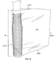
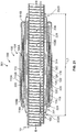
- a cover assembly 100 according to some embodiments of the present invention is shown therein.
- the cover assembly 100 may be used to cover and electrically insulate electrical substrates such as cables and connectors.
- the cover assembly 100 may be provided as a pre-expanded cover assembly unit 101 including a holdout device 102 , as shown in FIG. 1 , wherein the cover assembly 100 is in an expanded state or position.
- the cover assembly 100 is shown in a folded position or state in FIG. 1 .
- the cover assembly 100 may be deployed and mounted on the intended substrate in a retracted state or position as shown in FIGS. 6 and 7 and discussed in more detail below.
- the cover assembly 100 is shown in an unfolded position or state in FIGS. 6 and 7 .
- the cover assembly 100 is a cold shrink cover, meaning that it can be shrunk or retracted about the substrate without requiring the use of applied heat.
- the cover assembly 100 has a lengthwise axis A-A. According to some embodiments, the cover assembly 100 is provided pre-installed and pre-expanded on the holdout 102. In the folded state or position shown in FIG. 1 , the cover assembly 100 has first and second opposite ends 103A, 103B.
- the cover assembly 100 may be used to cover and seal a connection or splice between two or more cables 40 , 50 including a connector 60 to form a connection assembly 10 as shown in FIGS. 6 and 7 .
- the cables 40 , 50 are concentric neutral cables.
- the cover assembly 100 includes an outer sleeve (or re-jacket) 104.
- the outer sleeve 104 has first and second opposed ends 106A , 106B ( FIG. 1 ).
- the outer sleeve 104 is tubular and defines an axially extending conductor through passage 108 that communicates with opposed end openings 144A , 144B ( FIG. 7 ).
- first and second outer sections 110A, 110B of the outer sleeve 104 are folded back on an intermediate section 112 of the outer sleeve 104 at annular folds 114A, 114B.
- first outer section 110A of the outer sleeve 104 may be folded back on the intermediate section 112 of the outer sleeve 104 at the annular fold 114A and the second outer section 110B of the outer sleeve 104 may be folded back on the first outer section 110A and the intermediate section 112 of the outer sleeve 104 at the annular fold 114B.
- the cover assembly 100 includes a first retention layer 116 and a first friction reducing layer or tube (or first low friction layer or tube) 118 between the intermediate section 112 and the first outer section 110A of the outer sleeve 104.
- the cover assembly 100 includes a second retention layer 120 and a second friction reducing layer or tube (or second low friction layer or tube) 122 between the first and second outer sections 110A, 110B of the outer sleeve 104.
- the first and second retention layers 116, 120 help to maintain or retain the flipped outer sleeve 104 in place during expansion. That is, the first and second retention layers 116, 120 help prevent the outer sleeve 104 from unrolling while it is expanded onto the holdout 102.
- a coefficient of friction between the friction reducing layers 118, 122 and the outer tube 104 is less than a coefficient of friction between the retention layers 116, 120 and the outer tube 104. In some embodiments, a coefficient of friction between the retention layers 116, 120 and the outer sleeve 104 is less than a coefficient of friction between overlapping layers of the outer sleeve 104.
- the cover assembly 100 may include a first lubrication layer 124 between the first friction reducing layer 118 and the first outer section 110A of the outer sleeve 104.
- the cover assembly 100 may include a second lubrication layer 126 between the second friction reducing layer 122 and the second outer section 110B of the outer sleeve 104.
- the outer sleeve 104 can be formed of any suitable material. According to some embodiments, the outer sleeve 104 is formed of an electrically insulative material. According to some embodiments, the outer sleeve 104 is formed of an elastically expandable material. According to some embodiments, the outer sleeve 104 is formed of an elastomeric material. According to some embodiments, the outer sleeve 104 is formed of ethylene propylene diene monomer (EPDM) rubber. Other suitable materials may include neoprene or other rubber. According to some embodiments, the outer sleeve 104 has a Modulus at 100 percent elongation (M100) in the range of from about 0.6 to 1.1 MPa. The outer sleeve 104 may be formed by any suitable method and apparatus. For example, the outer sleeve 104 may be extruded or molded.
- M100 Modulus at 100 percent elongation
- the thickness T1 ( FIG. 1 ) of the outer sleeve 104 is in the range of from about 0.030 to 0.31 inches. According to some embodiments, the length L2 ( FIG. 6 ) of the outer sleeve 104 is in the range of from about 15 to 35 inches.
- the first and second retention layers 116, 120 may be tubular sleeves.
- the retention layers 116, 120 may be formed of a polymeric material (e.g ., vinyl) mesh.
- the first and second friction reducing layers 118, 122 may be thin, pliable layers.
- the first and second friction reducing layers 118, 122 may be formed of a polymeric material such as polyethylene, MylarTM, polyester, or nylon.
- the first and second friction reducing members 118, 122 are tubes that are received around the first and second retention layers 116, 120 , respectively.
- the first and second friction reducing layers 118, 122 may be in the form of a flexible tube that has an inner diameter or width that is greater than an outer diameter of the outer sleeve 104 and the corresponding retention layer 116,120 received therearound.
- each friction reducing layer 118, 122 is in the form of a flexible tube and is wrapped around the outer sleeve 104 and the corresponding retention layer 116, 120 multiple times such that each friction reducing layer 118, 122 includes multiple wraps or overlapping or superimposed layer sections of friction reducing material such as polyethylene.
- each friction reducing layer 118, 122 may include multiple flexible tubes that are each wrapped around the outer sleeve 104 and the corresponding retention layer 116, 120 multiple times to provide an even greater number of layers of friction reducing material such as polyethylene.
- Each friction reducing layer 118, 122 may have thickness of between about 0.02 and 0.2 mm.
- the first and second lubrication layers 124, 126 may be formed of any suitable flowable or viscous lubricant such as grease.
- the first and second retention layers 116, 120 do not include fluid or lubricant. Therefore, the first and second retention layers 116, 120 may be "dry" meaning that only the material making up the first and second retention layers 116, 120 are between the outer sleeve 104 and the first and second friction reducing layers 118, 122.
- the first and second retention layers 116, 120 may each only include a polymeric mesh layer.
- the holdout 102 includes a flexible strip 102A helically wound to form a holdout body in the form of a rigid cylinder 102B defining a holdout passage 102D.
- the strip 102A includes a pull cord 102C extending from a distal end 102E of the cylinder 102B and through the passage 102D and beyond the proximal end 102F of the cylinder 102B.
- the holdout device 102 may be factory installed.
- the holdout 102 can be formed of any suitable material.
- the holdout 102 is formed of a semi-rigid or rigid plastic.
- the holdout 102 is formed of polypropylene, PVC or ABS.
- the pre-expanded unit 101 may be used in the following manner to apply the cover 100 over a splice connection 15 ( FIG. 4 ) between a pair of electrical power transmission cables 40 , 50 to form a connection assembly 10.
- the cables 40 , 50 are low-voltage or medium-voltage (e.g. , between about 5 and 46 kV) power transmission cables.
- the cable 40 includes a primary electrical conductor 42 , a polymeric insulation layer 44 , a semiconductor layer 45 , one or more neutral conductors 46 , and a jacket 48 , with each component being concentrically surrounded by the next.
- the neutral conductors 46 are individual wires, which may be helically wound about the semiconductor layer 45.
- the primary conductor 42 may be formed of any suitable electrically conductive materials such as copper (solid or stranded).
- the polymeric insulation layer 44 may be formed of any suitable electrically insulative material such as crosslinked polyethylene (XLPE) or EPR.
- the semiconductor layer 45 may be formed of any suitable semiconductor material such as carbon black with silicone.
- the neutral conductors 46 may be formed of any suitable material such as copper.
- the jacket 48 may be formed of any suitable material such as EPDM.
- the cable 50 is similarly constructed with a primary electrical conductor 52 , a polymeric insulation layer 54 , a semiconductor layer 55 , one or more neutral conductors 56 , and a jacket 58 corresponding to components 42 , 44 , 45 , 46 and 48 , respectively.
- connection assembly 10 may be formed and the cover assembly 100 may be installed as follows.
- the cables 40 , 50 are prepared as shown in FIG. 4 such that a segment of each layer extends beyond the next overlying layer.
- the pre-expanded unit 101 is slid over the cable 50 as shown in FIG. 4 .
- the inside diameter of the holdout 102 is greater than the outer diameter of each cable 40, 50 such that the inner diameter of the holdout 102 is sufficient to receive the prepared cable 40 , 50 and the connector 60 without undue effort.
- the inner diameter of the holdout 102 is at least as great as the outer diameter of the largest portion of the cables or connectors that are to be received in the passage 102D.
- the pre-expanded unit 101 may be retained or parked on the cable 50 until the operator is ready to install the cover assembly 100 on the cables 40 , 50.
- the electrical connector 60 is secured to each primary conductor 42 , 52 to mechanically and electrically couple the primary conductors 42 , 52 to one another as shown in FIG. 4 .
- the connector 60 may be any suitable type of connector such as a metal crimp connector.
- the pre-expanded unit 101 is then slid into position over the connector 60 as shown in FIG. 5 .
- the holdout 102 is then removed from the cover assembly 100 , thereby permitting the elastomeric sleeve 104 to relax and radially retract about the cables 40 , 50 and the connector 60.
- the outer sleeve 104 overlaps and engages the semiconductor layers 44 , 54 of the cables 40 , 50.
- the holdout 102 is removed by pulling the pull cord 102C through the passage 102D ( e.g. , from the distal end 102E to the proximal end 102F ).
- the strip 102A is progressively removed from the distal end 102E , causing the cylinder 102B to progressively disintegrate from the distal end 102E.
- This permits the outer sleeve 104 to contract radially inwardly. This process is continued until the cylinder 102B is fully disintegrated and the strip 102A removed from the outer sleeve 104 as illustrated in FIGS. 6 and 7 .
- Strips of sealant 64 may be applied to the outer surfaces of the cable jackets 48, 58.
- the operator then rolls each of the extension or outer sections 110A, 110B of the outer sleeve 104 axially outwardly to cover the adjacent sections of the cables 40 and 50 , respectively.
- at least a portion of each extension section 110A, 110B overlaps a respective portion of each cable jacket 48 , 58 and engages the associated sealant strip 64 to provide a moisture seal.
- the cover assembly 100 is thereby fully installed to form the connection assembly 10 as shown in FIGS. 6 and 7 .
- the operator may unroll (slide) the second outer section 110B of the outer sleeve 104 axially outwardly in the axial direction D1 to cover an adjacent section of the cable 50.
- the operator may then unroll (slide) the first outer section 110A of the outer sleeve 104 axially outwardly in the opposite axial direction D2 to cover an adjacent section of the cable 40.
- the operator may then remove the friction reducing layers 118, 122 and the retention layers 116, 120 from the outer sleeve 104.
- the relaxed inner diameter of the outer sleeve 104 is less than at least the outer diameter of the jacket layers 48 , 58. Therefore, the outer sleeve 104 exerts a radially inwardly compressive or clamping force or pressure (due to elastic tension) onto the cables 40, 50. The outer sleeve 104 thereby effects a liquid tight seal at the interface between the cable jackets 48, 58 and the outer sleeve 104. This seal can protect the cable and the splice from the ingress of environmental moisture. According to some embodiments the relaxed inner diameter of the outer sleeve 104 is at least 10% less than the smallest diameter cable upon which the cover assembly 100 is intended to be installed.
- Cover assemblies and methods of the present invention and as described herein can provide a number of advantages.
- Known cover assemblies or rubber jackets include a mesh tube and grease between the folded layers of the rubber in an effort to make it easier for an operator to unroll or slide open the jacket (e.g., to unroll one of the layers of rubber away from another layer of rubber with the mesh tube and the grease therebetween).
- the mesh has a tendency to dig into the rubber of the jacket and the grease tends to settle in the openings of the mesh.
- the grease may also be absorbed into the rubber. This is particularly the case when the jacket is handled frequently and/or is stored for a long period of time before use.
- the jacket becomes difficult to unroll when the mesh digs into the rubber, when the grease settles in the openings of the mesh, and/or when the grease is absorbed in the rubber.
- layers of rubber of the outer sleeve may directly contact each other resulting in a high friction interface that makes it difficult or practically impossible to unroll or slide the jacket.
- Embodiments of the present invention address these problems at least in part by providing the friction reducing layers 118, 122.
- the friction reducing layers 118, 122 provides a low friction surface which makes unrolling the cover assembly 100 easier than with known covers or jackets.
- the second friction reducing layer 122 allows for easier sliding of the second outer section 110B of the outer sleeve 104 away from the first outer section 110A of the outer sleeve 104 in the direction D1.
- the first friction reducing layer 118 allows for easier sliding of the first outer section 110A of the outer sleeve 104 away from the intermediate section 112 of the outer sleeve 104 in the direction D2. Therefore, the friction reducing layers 118, 122 facilitate easier sliding and help inhibit bonding.
- the grease layers 124, 126 may also facilitate easier unrolling of the cover assembly 100.
- the friction reducing layers 118, 122 may be formed by thin, flexible tubes that are wrapped around the outer sleeve 104 and the corresponding retention layers 116, 120 multiple times. This can provide a more robust low friction surface that is less likely to fail by tearing (or if an upper layer or wrap tears, lower layers or wraps to maintain the low friction surface).
- the present inventors also found that wrapping the flexible tube multiple times around the sleeve and corresponding mesh tube results in the friction reducing layer having wrinkles which further reduce the friction and allows for easier unrolling.
- the first and second retention layers 116, 120 help prevent the outer sleeve 104 from unrolling while it is expanded onto the holdout 102.
- the retention layers 116, 120 can provide an intermediate friction surface were the friction reducing layers 118, 122 to fail. This may allow an operator to unroll or slide the cover assembly 100 in the event that the one or more of the friction reducing layers 118, 122 or portions thereof fail during unrolling, albeit using increased force.
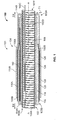
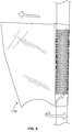
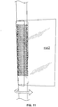
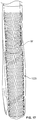
- FIG. 2 is a perspective view of the cover assembly 100 without the holdout.
- FIGS. 8-19 illustrate an example of a process of forming the cover assembly 100 of FIG. 2 .
- an elastomeric tube T may be positioned on a mandrel and clamped in a bench vise.
- the tube T may be formed of, for example, EPDM.
- the tube T ultimately forms the outer sleeve 104 of the cover assembly ( FIG. 1 ).
- a generally cylindrical mesh tube corresponding to the first retention layer 116 is received around the tube T.
- the mesh tube 116 may be at least partially held in place by friction.
- the mesh tube 116 may have a length L3 between about 50 and 300 mm and, in some embodiments, may have a length of about 150 mm.
- a first flexible tube 118t is positioned over the mesh tube 116 and pulled to one side.
- the first flexible tube 118t may be formed of, for example, polyethylene.
- the first flexible tube includes first and second opposite open ends 118E1 , 118E2 and first and second opposite closed sides 118S1 , 118S2.
- the mesh tube 116 is received in a passage of the first flexible tube 118t that is defined between the first and second open ends 118E1, 118E2.
- the first flexible tube 118t has an inner diameter or width D5 that is substantially larger than an outer diameter D6 of the tube T (and/or the mesh tube 116 ).
- the width D5 may correspond to the distance between the first and second closed sides 118S1 , 118S2.
- the diameter or width D5 of the first flexible tube 118t may be between about 100 and 300 mm and, in some embodiments, is about 200 mm.
- the outer diameter D6 of the tube T may be between about 40 and 60 mm and, in some embodiments, is about 50 mm.
- the flexible tube 118t may have a circular cross section when expanded.
- the flexible tube 118t may have an elliptical or lens-shaped (e.g., pointed elliptical) cross section when expanded.
- the "diameter" D5 of the flexible tube 118t refers to the length along the major axis of the shape.
- the shape and relative large inner diameter of the flexible tube 118t allows the tube T and the mesh tube 116 to be received lengthwise along an inner surface of one of the sides 118S1, 118S2 of the flexible tube 118t and allows the opposite one of the sides 118S1, 118S2 of the tube 118t to be pulled away from the tube T such that the flexible tube 118t extends away from the tube T.
- the flexible tube 118t may then be wrapped around the mesh tube 116 and the tube T multiple times. As illustrated in FIG. 10 , the flexible tube 118t includes wrinkles W when wrapped in this manner.
- the flexible tube 118t may have a length L4 such that the first flexible tube extends past the mesh tube 116 toward the second end 106B of the tube T.
- the length L4 of the flexible tube 118t may be between about 100 and 300 mm and, in some embodiments, is about 200 mm.
- the flexible tube 118t corresponds to the friction reducing layer 118. More than one of the flexible tubes 118t may be used.
- the flexible tube 118t described above is a first flexible tube 118t1 and a second flexible tube 118t2 is positioned and wrapped around the first flexible tube 118t1 in a similar manner to that described in reference to FIGS. 8-10 .
- the second flexible tube 118t2 may be the same or substantially the same as the first flexible tube 118t1.
- the first and second flexible tubes 118t1, 118t2 form the first friction reducing layer 118. This is illustrated in FIGS. 11 and 12 .
- more than two of the flexible tubes 118t may be wrapped to form the first friction reducing layer 118.
- the wrapping of the flexible tube(s) and/or the use of multiple flexible tubes may provide a more robust friction reducing surface (and may provide a friction reducing layer that has additional wrinkles).
- grease may be applied to the outermost of the flexible tubes 118t.
- the grease corresponds to the first lubrication layer 124.
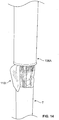
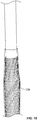
- the tube T may be grasped at the first end 106A thereof and flipped down over the flexible tube(s) 118t.
- an outer surface of the tube T faces the flexible tube(s) 118t.
- an end of the flexible tubes(s) 118t extends past the first end 106A of the tube T. This may help ensure that the outer sleeve 104 does not contact itself during the later unrolling of the cover assembly 100 (e.g., to avoid rubber-to-rubber contact).
- FIG. 14 may help ensure that the outer sleeve 104 does not contact itself during the later unrolling of the cover assembly 100 (e.g., to avoid rubber-to-rubber contact).
- the friction reducing layer 118 extends past the first end 106A of the outer sleeve 104 to help ensure that the first outer section 110A of the outer sleeve 104 does not contact the intermediate section 112 of the outer sleeve 104 during unrolling.
- the mandrel may be turned upside-down and re-clamped in the bench vise.
- a mesh tube 120 corresponding to the second retention layer 120 is positioned around the tube T at the mark M2 and extends over the first end 106A of the tube T.
- the mesh tube 120 may be longer than the mesh tube 116.
- the mesh tube may have a length L5 of between about 50 and 400 mm and, in some embodiments, has a length L5 of about 230 mm.
- a flexible tube 122t includes first and second opposite open ends 122E1, 122E2 and first and second opposite closed sides 122S1, 122S2.
- the flexible tube 122t is received over and wrapped around the tube T and the mesh tube 120 in the same way as described above in reference to the flexible tube 118t.
- the flexible tube 122t is a first flexible tube and a second flexible tube 122t is wrapped around the first flexible tube.
- more than two flexible tubes may be sequentially wrapped.
- the flexible tube(s) 122t form the second friction reducing layer 122. Wrinkles W may be in the second friction reducing layer 122.
- the flexible tube 122t may be substantially similar to the flexible tube 118t but may have a greater length.
- the flexible tube 122t may have a length L6 of between about 50 and 400 mm and, in some embodiments, has a length L6 of about 230 mm.
- Grease may then be applied to the outermost flexible tube 122t as shown in FIG. 18 .
- the applied grease may form the second lubrication layer 126.
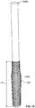
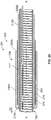
- the second end 106B of the tube T may be flipped down to form the completed cover assembly 100.
- an end of the flexible tubes(s) 122t extends past the second end 106B of the tube T. This may help ensure that the outer sleeve 104 does not contact itself during the later unrolling of the cover assembly 100 (e.g., to avoid rubber-to-rubber contact).
- FIG. 19 shows that the outer sleeve 104 does not contact itself during the later unrolling of the cover assembly 100 (e.g., to avoid rubber-to-rubber contact).
- the friction reducing layer 122 extends past the second end 106B of the outer sleeve 104 to help ensure that the second outer section 110B of the outer sleeve 104 does not contact the first outer section 110A of the outer sleeve during unrolling.
- a cover assembly 200 according to some other embodiments of the present invention is shown in FIG. 20 .
- the cover assembly 200 is similar to the cover assembly 100 with the primary differences being described below.
- the cover assembly 200 includes one, rather than two, outer sections that can be unrolled.
- the cover assembly 200 may used to cover cables at or adjacent cable terminations, for example.
- the cover assembly 200 may be provided as a pre-expanded cover assembly unit 201 including a holdout device 102 , as shown in FIG. 20 , wherein the cover assembly 200 is in an expanded state or position.
- the cover assembly 200 includes an outer sleeve 204.
- the outer sleeve 204 includes first and second opposite ends 206A, 206B.
- the outer sleeve 204 includes a first outer section 210A that is folded back on an intermediate section 212 and/or a second outer section 210B of the outer sleeve 204 at annular fold 214A.
- a retention layer 216 is between the first outer section 210A of the sleeve 204 and the intermediate section 212 and/or the second outer section 210B of the sleeve 204.
- the retention layer 216 may be the same or substantially the same as the retention layer 116 described above.
- a friction reducing layer 218 is between the retention layer 216 and the intermediate section 212 and/or the second outer section 210B of the sleeve 204.
- the friction reducing layer 218 may be the same or substantially the same as the friction reducing layer 118 described above.
- the friction reducing layer 218 may extend axially past the first end 206A of the sleeve 204.
- a lubrication layer 224 is between the friction reducing layer 218 and the intermediate section 212 and/or the second outer section 210B of the sleeve 204.
- the lubrication layer 224 may be the same or substantially the same as the lubrication layer 124 described above.
- the cover assembly 200 may be assembled in a similar way to that shown in FIGS. 8-14 .
- the tube T may be shorter than as shown in FIGS. 8-14 .
- a cover assembly 300 according to some other embodiments of the present invention is shown in FIG. 21 .
- the cover assembly 300 may be used to cover and electrically insulate electrical substrates such as cables and connectors.
- the cover assembly 300 may be provided as a pre-expanded cover assembly unit 301 including a holdout device 102 , as shown in FIG. 21 , wherein the cover assembly 300 is in an expanded state or position.
- the cover assembly 300 may be deployed and mounted on the intended substrate in a retracted state or position in a similar manner as described above in reference to the cover assembly 100.
- the cover assembly 300 is a cold shrink cover, meaning that it can be shrunk or retracted about the substrate without requiring the use of applied heat.
- the cover assembly 300 provides an "all-in-one" integral unit that can be installed in similar fashion to known cold shrink splice cover insulating tubes.
- the cover assembly 300 includes the cover assembly 100 and therefore shares the associated advantages described above.
- the cover assembly 300 includes the cover assembly 100 , a metal contact layer 314 , a Faraday cage layer 322, two stress cone layers 324 , an inner sleeve (or insulation body) 330 , and a semiconductor layer 339 , as discussed in more detail below.
- the Faraday cage layer 322 , the stress cone layers 324 , and the inner sleeve 330 are bonded ( e.g. , adhered or molded) together to form a unitary component in the form of an inner sleeve assembly 331.
- the cover assembly 300 may be used to cover and seal a connection or splice between two or more cables 40 , 50 including a connector 60 to form a connection assembly 10 , similar to as shown in FIGS. 3-7 .
- the cover assembly 300 has a lengthwise axis B-B.
- the Faraday cage layer 322 , the stress cone layers 324 , the inner sleeve 330 , and the semiconductor layer 339 are provided as an integral, unitary structure extending lengthwise along the axis B-B.
- the cover assembly 300 is provided pre-installed and pre-expanded on the holdout 102.
- the inner sleeve 330 has opposed ends 332A , 332B.
- the inner sleeve 330 is tubular and defines an axially extending conductor through passage 336
- the Faraday cage layer 322 is illustrated as a generally tubular sleeve bonded to the inner surface 320 of the inner sleeve 330.
- the Faraday cage layer 322 may be formed of a suitable elastically conductive elastomer. In use, the Faraday cage layer 322 may form a Faraday cage to provide an equal potential volume about the connector 60 so that an electric field is cancelled in the surrounding air voids.
- the stress cone layers 324 are illustrated as generally tubular sleeves bonded to the inner surface 330A of the inner sleeve 330 at either end 332A , 332B thereof.
- the stress cone layers 324 may be formed of a suitable electrically conductive elastomer. In use, the stress cone layers 324 may serve to redistribute the voltage along the surface of the cable insulation 44, 54 to reduce or prevent the degradation of the insulation 44, 54 that might otherwise occur.
- the layers 322 , 324 are formed of a material having a Modulus at 100 percent elongation (M100) in the range of from about 0.68 to 0.88 MPa.
- the semiconductor layer 339 fully circumferentially surrounds the inner sleeve 330. According to some embodiments, the semiconductor layer 339 is coextensive with the inner sleeve 330.
- the metal contact layer 314 is an electrically conductive, tubular sleeve surrounding and contacting the semiconductor layer 339.
- the metal contact layer 314 is a copper mesh wrap or sock.
- the metal contact layer 314 extends around and contacts the first annular fold 114A of the outer sleeve 104 , the first outer section 110A of the outer sleeve 104 , the second annular fold 114B of the outer sleeve 104 , and the second outer section 110B of the outer sleeve 104.
- the semiconductor layer 339 can be formed of any suitable electrically semiconductive material. According to some embodiments, the semiconductor layer 339 is formed of an elastically expandable material. According to some embodiments, the semiconductor layer 339 is formed of an elastomeric material. According to some embodiments, the semiconductor layer 339 is formed of carbon black and silicone. Other suitable materials may include carbon black and EPDM.
- the inner sleeve 330 can be formed of any suitable material. According to some embodiments, the inner sleeve 330 is formed of a dielectric or electrically insulative material. According to some embodiments, the inner sleeve 330 is formed of an elastically expandable material. According to some embodiments, the inner sleeve 330 is formed of an elastomeric material. According to some embodiments, the inner sleeve 330 is formed of liquid silicone rubber (LSR). Other suitable materials may include EPDM or ethylene propylene rubber (EPR). According to some embodiments, the inner sleeve 330 has a Modulus at 100 percent elongation (M100) in the range of from about 0.4 to 0.52 MPa.
- M100 Modulus at 100 percent elongation
- the thickness T2 of the inner sleeve 330 is in the range from about 0.07 to 2 inches. According to some embodiments, the length L1 of the inner sleeve 330 is in the range from about 8 to 30 inches.
- the holdout device 102 may be factory installed.
- the holdout 102 can be formed of any suitable material.
- the holdout 102 is formed of a semi-rigid or rigid plastic.
- the holdout 102 is formed of polypropylene, PVC or ABS.
- the cover assembly 300 may be formed by any suitable method and apparatus. According to some embodiments, the inner sleeve 330 is molded and the outer sleeve 104 is thereafter insert overmolded about the inner sleeve 330.
- the inner sleeve 330 and the outer sleeve 104 are separately formed (for example, by molding or extrusion) and thereafter the outer sleeve 104 is mounted on the inner sleeve 330.
- the inner sleeve 330 is unitarily molded.
- the outer sleeve 104 is unitarily molded.
- the inner sleeve 330 and/or the outer sleeve 104 may be extruded.
- the inner sleeve 330 and/or the outer sleeve 104 is unitarily extruded.
- the pre-expanded unit 301 may be used in the manner described above in connection with FIGS. 3-7 to apply the cover 300 over a splice connection 15 ( FIG. 4 ) between a pair of electrical power transmission cables 40 , 50 to form a connection assembly.
- the pre-expanded unit 301 may be slid into position over the connector 60 similar to the pre-expanded unit 101 in FIG. 5 .
- the holdout 102 is then removed from the cover assembly 300 , thereby permitting the elastomeric sleeves 330 , 104 to relax and radially retract about the cables 40 , 50 and the connector 60.
- the inner sleeve 330 overlaps and engages the semiconductor layers 44 , 54 of the cables 40 , 50.
- the holdout 102 is removed in the same or similar manner as described above in reference to the pre-expanded unit 101. This in turn permits the inner sleeve 330 and the outer sleeve 104 to contract radially inwardly.
- each of the extension sections 110A, 110B of the outer sleeve 104 rolls (slides) each of the extension sections 110A, 110B of the outer sleeve 104 axially outwardly to cover the adjacent sections of the cables 40 and 50 , respectively.
- the cover assembly 100 including the first and second friction reducing layers 118, 122 facilitates easier unrolling (sliding) of the outer sections 110A, 110B of the outer sleeve 104 axially outwardly.
- Cover assemblies according to some embodiments of the present invention may include additional layers and/or certain layers may be omitted.
- cover assemblies in accordance with some embodiments of the present invention may be formed without the semiconductor layer 139.
- One or more additional layers may be interposed between the inner sleeve 130 and the outer sleeve 140.
- Cover assemblies according to embodiments of the invention may be used for all cold shrinkable products that require the field installer to unroll the EPDM jacket such as Cold Shrink Joints (CSJ) and Cold Applied Transition Joints (CATJ).
- Cover assemblies according to embodiments of the invention may be used for any suitable cables and connections. Such cable assemblies may be adapted for use, for example, with connections of medium voltage cables up to about 46 kV. In some applications, the cover assemblies are installed on underground residential distribution (URD) cable splices.
- UTD underground residential distribution
Landscapes
- Physics & Mathematics (AREA)
- Spectroscopy & Molecular Physics (AREA)
- Cable Accessories (AREA)
- Insulating Bodies (AREA)
Description
- This application claims priority from
U.S. Provisional Application No. 62/425,345, filed November 22, 2016 - The present invention relates to electrical cables and connections and, more particularly, to protective covers for electrical cables and electrical connections.
- Cold shrinkable covers are commonly employed to protect or shield electrical power cables and connections (e.g., low voltage cables up to about 1000 V and medium voltage cables up to about 46 kV). Examples of cold shrinkable covers for use with electrical power cables and connections include the "All - in - One" CSJA Cold Shrinkable joint, available from TE Connectivity. This product includes a splice body that is positioned over the connector and installed by releasing a holdout from the splice body. The splice body includes a re-jacketing sleeve that is unfolded and slid axially onto the jackets of the connected cables. However, such unfolding and sliding can be difficult for the operator in some instances. A prior art covering device for sealing a connection in an electrical cable is disclosed in patent
US 5753861 . - The device includes a rigid support surrounded by an elastic sleeve, end portions of which are folded back so as to lie on an outer surface of the sleeve. A layer of friction reducing material may be provided between the folded back end portions and the outer surface of the sleeve. Ends of the support may extend beyond the sleeve with folded back end portions and these support ends may include frangible sections which can be broken to permit collapsing of the support ends towards a cable extending into the covering device. Covering devices in the same field are also disclosed in patents
WO 2013/096145 A2 ,WO 98/27632 A1 US 2010279542 . - Some embodiments of the present invention are directed to an integral, unitary pre-expanded cover assembly unit for covering an electrical connection between first and second electrical cables each having a primary conductor and a neutral conductor includes a cover assembly and a removable holdout. The cover assembly includes an elastomeric outer sleeve defining a cable passage to receive the electrical connection and the primary conductors of the first and second cables. The outer sleeve includes an intermediate section and first and second outer sections. With the cover assembly in a folded state or position, the first outer section is folded at a first annular fold and is on the intermediate section. With the cover assembly in the folded state or position, the second outer section is folded at a second annular fold and is on the first outer section. With the cover assembly in the folded state or position, the cover assembly includes: a first retention layer between the intermediate section and the first outer section of the outer sleeve; a first friction reducing layer between the first retention layer and the first outer section of the outer sleeve; a second retention layer between the first outer section and the second outer section of the outer sleeve; and a second friction reducing layer between the second retention layer and the second outer section of the outer sleeve. The holdout is mounted within outer sleeve. The holdout is operative to temporarily maintain the outer sleeve in an expanded state. The cover assembly is movable from the folded position or state to an unfolded position or state by sliding the second outer section of the outer sleeve in a first axial direction away from the intermediate section of the outer sleeve and by sliding the first outer section of the outer sleeve in a second, opposite axial direction away from the intermediate section of the outer sleeve.
- Some other embodiments of the present invention are directed to an integral, unitary pre-expanded cover assembly unit according to claim 14 for covering an electrical connection between first and second electrical cables each having a primary conductor.
- Some other embodiments of the invention are directed to a method for covering an electrical connection as set out in the independent method claim.
- Further features, advantages and details of the present invention will be appreciated by those of ordinary skill in the art from a reading of the figures and the detailed description of the preferred embodiments that follow, such description being merely illustrative of the present invention,
-
-
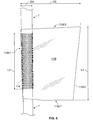
FIG. 1 is a cross-sectional view of a pre-expanded cover assembly unit including a cover assembly and a holdout device according to some embodiments of the present invention. -
FIG. 2A is a perspective view of the cover assembly ofFIG. 1 shown without the holdout device. -
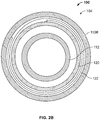
FIG. 2B is a cross-sectional view of the cover assembly ofFIG. 2A taken along theline 2B-2B. -
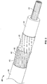
FIG. 3 is a perspective view of an exemplary concentric neutral cable. -
FIGS. 4-6 are side views illustrating procedures for installing the cover assembly unit ofFIG. 1 on a pair of concentric neutral cables coupled by a connector to form a splice connection. -
FIG. 7 is a cross-sectional view of the covered splice connection ofFIG. 6 . -
FIGS. 8-19 illustrate an example process for making the cover assembly ofFIG 2 . -
FIG. 20 is a cross-sectional view of a pre-expanded cover assembly unit including a cover assembly and a holdout device according to some other embodiments of the present invention. -
FIG. 21 is a cross-sectional view of a pre-expanded cover assembly unit including a cover assembly and a holdout device according to some other embodiments of the present invention. - The present invention now will be described more fully hereinafter with reference to the accompanying drawings, in which illustrative embodiments of the invention are shown. In the drawings, the relative sizes of regions or features may be exaggerated for clarity. This invention may, however, be embodied in many different forms and should not be construed as limited to the embodiments set forth herein; rather, these embodiments are provided so that this disclosure will be thorough and complete, and will fully convey the scope of the invention to those skilled in the art.
- It will be understood that when an element is referred to as being "coupled" or "connected" to another element, it can be directly coupled or connected to the other element or intervening elements may also be present. In contrast, when an element is referred to as being "directly coupled" or "directly connected" to another element, there are no intervening elements present. Like numbers refer to like elements throughout. As used herein the term "and/or" includes any and all combinations of one or more of the associated listed items.
- In addition, spatially relative terms, such as "under", "below", "lower", "over", "upper" and the like, may be used herein for ease of description to describe one element or feature's relationship to another element(s) or feature(s) as illustrated in the figures. It will be understood that the spatially relative terms are intended to encompass different orientations of the device in use or operation in addition to the orientation depicted in the figures. For example, if the device in the figures is turned over, elements described as "under" or "beneath" other elements or features would then be oriented "over" the other elements or features. Thus, the exemplary term "under" can encompass both an orientation of over and under. The device may be otherwise oriented (rotated 90 degrees or at other orientations) and the spatially relative descriptors used herein interpreted accordingly.
- The terminology used herein is for the purpose of describing particular embodiments only and is not intended to be limiting of the invention. As used herein, the singular forms "a", "an" and "the" are intended to include the plural forms as well, unless the context clearly indicates otherwise. It will be further understood that the terms "comprises" and/or "comprising," when used in this specification, specify the presence of stated features, integers, steps, operations, elements, and/or components, but do not preclude the presence or addition of one or more other features, integers, steps, operations, elements, components, and/or groups thereof.
- Unless otherwise defined, all terms (including technical and scientific terms) used herein have the same meaning as commonly understood by one of ordinary skill in the art to which this invention belongs. It will be further understood that terms, such as those defined in commonly used dictionaries, should be interpreted as having a meaning that is consistent with their meaning in the context of the relevant art and will not be interpreted in an idealized or overly formal sense unless expressly so defined herein.
- With reference to
FIGS. 1-7 , acover assembly 100 according to some embodiments of the present invention is shown therein. - The
cover assembly 100 may be used to cover and electrically insulate electrical substrates such as cables and connectors. Thecover assembly 100 may be provided as a pre-expandedcover assembly unit 101 including aholdout device 102, as shown inFIG. 1 , wherein thecover assembly 100 is in an expanded state or position. Thecover assembly 100 is shown in a folded position or state inFIG. 1 . Thecover assembly 100 may be deployed and mounted on the intended substrate in a retracted state or position as shown inFIGS. 6 and7 and discussed in more detail below. Thecover assembly 100 is shown in an unfolded position or state inFIGS. 6 and7 . According to some embodiments, thecover assembly 100 is a cold shrink cover, meaning that it can be shrunk or retracted about the substrate without requiring the use of applied heat. - Referring to
FIGS. 1 ,2A and2B , thecover assembly 100 has a lengthwise axis A-A. According to some embodiments, thecover assembly 100 is provided pre-installed and pre-expanded on theholdout 102. In the folded state or position shown inFIG. 1 , thecover assembly 100 has first and second opposite ends 103A, 103B. - The
cover assembly 100 may be used to cover and seal a connection or splice between two ormore cables connector 60 to form aconnection assembly 10 as shown inFIGS. 6 and7 . According to some embodiments, thecables - The
cover assembly 100 includes an outer sleeve (or re-jacket) 104. Theouter sleeve 104 has first and second opposed ends 106A, 106B (FIG. 1 ). Theouter sleeve 104 is tubular and defines an axially extending conductor throughpassage 108 that communicates withopposed end openings FIG. 7 ). When mounted on theholdout 102 in the folded position or state as shown inFIG. 1 , first and secondouter sections outer sleeve 104 are folded back on anintermediate section 112 of theouter sleeve 104 atannular folds outer section 110A of theouter sleeve 104 may be folded back on theintermediate section 112 of theouter sleeve 104 at theannular fold 114A and the secondouter section 110B of theouter sleeve 104 may be folded back on the firstouter section 110A and theintermediate section 112 of theouter sleeve 104 at theannular fold 114B. - The
cover assembly 100 includes afirst retention layer 116 and a first friction reducing layer or tube (or first low friction layer or tube) 118 between theintermediate section 112 and the firstouter section 110A of theouter sleeve 104. Thecover assembly 100 includes asecond retention layer 120 and a second friction reducing layer or tube (or second low friction layer or tube) 122 between the first and secondouter sections outer sleeve 104. - The first and second retention layers 116, 120 help to maintain or retain the flipped
outer sleeve 104 in place during expansion. That is, the first and second retention layers 116, 120 help prevent theouter sleeve 104 from unrolling while it is expanded onto theholdout 102. - In some embodiments, a coefficient of friction between the
friction reducing layers outer tube 104 is less than a coefficient of friction between the retention layers 116, 120 and theouter tube 104. In some embodiments, a coefficient of friction between the retention layers 116, 120 and theouter sleeve 104 is less than a coefficient of friction between overlapping layers of theouter sleeve 104. - The
cover assembly 100 may include afirst lubrication layer 124 between the firstfriction reducing layer 118 and the firstouter section 110A of theouter sleeve 104. Thecover assembly 100 may include asecond lubrication layer 126 between the secondfriction reducing layer 122 and the secondouter section 110B of theouter sleeve 104. - The
outer sleeve 104 can be formed of any suitable material. According to some embodiments, theouter sleeve 104 is formed of an electrically insulative material. According to some embodiments, theouter sleeve 104 is formed of an elastically expandable material. According to some embodiments, theouter sleeve 104 is formed of an elastomeric material. According to some embodiments, theouter sleeve 104 is formed of ethylene propylene diene monomer (EPDM) rubber. Other suitable materials may include neoprene or other rubber. According to some embodiments, theouter sleeve 104 has a Modulus at 100 percent elongation (M100) in the range of from about 0.6 to 1.1 MPa. Theouter sleeve 104 may be formed by any suitable method and apparatus. For example, theouter sleeve 104 may be extruded or molded. - According to some embodiments, the thickness T1 (
FIG. 1 ) of theouter sleeve 104 is in the range of from about 0.030 to 0.31 inches. According to some embodiments, the length L2 (FIG. 6 ) of theouter sleeve 104 is in the range of from about 15 to 35 inches. - The first and second retention layers 116, 120 may be tubular sleeves. The retention layers 116, 120 may be formed of a polymeric material (e.g., vinyl) mesh.
- The first and second
friction reducing layers friction reducing layers friction reducing members friction reducing layers outer sleeve 104 and the corresponding retention layer 116,120 received therearound. According to some embodiments, and as also described in more detail below, eachfriction reducing layer outer sleeve 104 and thecorresponding retention layer friction reducing layer friction reducing layer outer sleeve 104 and thecorresponding retention layer friction reducing layer - The first and second lubrication layers 124, 126 may be formed of any suitable flowable or viscous lubricant such as grease.
- According to some embodiments, the first and second retention layers 116, 120 do not include fluid or lubricant. Therefore, the first and second retention layers 116, 120 may be "dry" meaning that only the material making up the first and second retention layers 116, 120 are between the
outer sleeve 104 and the first and secondfriction reducing layers - According to some embodiments, the
holdout 102 includes aflexible strip 102A helically wound to form a holdout body in the form of arigid cylinder 102B defining aholdout passage 102D. Thestrip 102A includes apull cord 102C extending from adistal end 102E of thecylinder 102B and through thepassage 102D and beyond theproximal end 102F of thecylinder 102B. - The
holdout device 102 may be factory installed. Theholdout 102 can be formed of any suitable material. According to some embodiments, theholdout 102 is formed of a semi-rigid or rigid plastic. In some embodiments, theholdout 102 is formed of polypropylene, PVC or ABS. - Referring now to
FIGS. 3-7 , thepre-expanded unit 101 may be used in the following manner to apply thecover 100 over a splice connection 15 (FIG. 4 ) between a pair of electricalpower transmission cables connection assembly 10. According to some embodiments, thecables FIG. 3 , thecable 40 includes a primaryelectrical conductor 42, apolymeric insulation layer 44, asemiconductor layer 45, one or moreneutral conductors 46, and ajacket 48, with each component being concentrically surrounded by the next. According to some embodiments and as shown, theneutral conductors 46 are individual wires, which may be helically wound about thesemiconductor layer 45. Theprimary conductor 42 may be formed of any suitable electrically conductive materials such as copper (solid or stranded). Thepolymeric insulation layer 44 may be formed of any suitable electrically insulative material such as crosslinked polyethylene (XLPE) or EPR. Thesemiconductor layer 45 may be formed of any suitable semiconductor material such as carbon black with silicone. Theneutral conductors 46 may be formed of any suitable material such as copper. Thejacket 48 may be formed of any suitable material such as EPDM. Thecable 50 is similarly constructed with a primaryelectrical conductor 52, apolymeric insulation layer 54, asemiconductor layer 55, one or moreneutral conductors 56, and ajacket 58 corresponding tocomponents - The
connection assembly 10 may be formed and thecover assembly 100 may be installed as follows. Thecables FIG. 4 such that a segment of each layer extends beyond the next overlying layer. - The
pre-expanded unit 101 is slid over thecable 50 as shown inFIG. 4 . According to some embodiments, the inside diameter of theholdout 102 is greater than the outer diameter of eachcable holdout 102 is sufficient to receive theprepared cable connector 60 without undue effort. According to some embodiments, the inner diameter of theholdout 102 is at least as great as the outer diameter of the largest portion of the cables or connectors that are to be received in thepassage 102D. Thepre-expanded unit 101 may be retained or parked on thecable 50 until the operator is ready to install thecover assembly 100 on thecables - The
electrical connector 60 is secured to eachprimary conductor primary conductors FIG. 4 . Theconnector 60 may be any suitable type of connector such as a metal crimp connector. - The
pre-expanded unit 101 is then slid into position over theconnector 60 as shown inFIG. 5 . Theholdout 102 is then removed from thecover assembly 100, thereby permitting theelastomeric sleeve 104 to relax and radially retract about thecables connector 60. According to some embodiments, theouter sleeve 104 overlaps and engages the semiconductor layers 44, 54 of thecables - More particularly, the
holdout 102 is removed by pulling thepull cord 102C through thepassage 102D (e.g., from thedistal end 102E to theproximal end 102F). As a result, thestrip 102A is progressively removed from thedistal end 102E, causing thecylinder 102B to progressively disintegrate from thedistal end 102E. This in turn permits theouter sleeve 104 to contract radially inwardly. This process is continued until thecylinder 102B is fully disintegrated and thestrip 102A removed from theouter sleeve 104 as illustrated inFIGS. 6 and7 . - Strips of
sealant 64 may be applied to the outer surfaces of thecable jackets outer sections outer sleeve 104 axially outwardly to cover the adjacent sections of thecables extension section cable jacket sealant strip 64 to provide a moisture seal. Thecover assembly 100 is thereby fully installed to form theconnection assembly 10 as shown inFIGS. 6 and7 . - More particularly, referring to
FIGS. 1 and6 , the operator may unroll (slide) the secondouter section 110B of theouter sleeve 104 axially outwardly in the axial direction D1 to cover an adjacent section of thecable 50. The operator may then unroll (slide) the firstouter section 110A of theouter sleeve 104 axially outwardly in the opposite axial direction D2 to cover an adjacent section of thecable 40. The operator may then remove thefriction reducing layers outer sleeve 104. - The relaxed inner diameter of the
outer sleeve 104 is less than at least the outer diameter of the jacket layers 48, 58. Therefore, theouter sleeve 104 exerts a radially inwardly compressive or clamping force or pressure (due to elastic tension) onto thecables outer sleeve 104 thereby effects a liquid tight seal at the interface between thecable jackets outer sleeve 104. This seal can protect the cable and the splice from the ingress of environmental moisture. According to some embodiments the relaxed inner diameter of theouter sleeve 104 is at least 10% less than the smallest diameter cable upon which thecover assembly 100 is intended to be installed. - Cover assemblies and methods of the present invention and as described herein can provide a number of advantages. Known cover assemblies or rubber jackets include a mesh tube and grease between the folded layers of the rubber in an effort to make it easier for an operator to unroll or slide open the jacket (e.g., to unroll one of the layers of rubber away from another layer of rubber with the mesh tube and the grease therebetween). However, the mesh has a tendency to dig into the rubber of the jacket and the grease tends to settle in the openings of the mesh. The grease may also be absorbed into the rubber. This is particularly the case when the jacket is handled frequently and/or is stored for a long period of time before use. The jacket becomes difficult to unroll when the mesh digs into the rubber, when the grease settles in the openings of the mesh, and/or when the grease is absorbed in the rubber. For example, layers of rubber of the outer sleeve may directly contact each other resulting in a high friction interface that makes it difficult or practically impossible to unroll or slide the jacket.
- Embodiments of the present invention address these problems at least in part by providing the
friction reducing layers friction reducing layers cover assembly 100 easier than with known covers or jackets. For example, referring toFIG. 1 , the secondfriction reducing layer 122 allows for easier sliding of the secondouter section 110B of theouter sleeve 104 away from the firstouter section 110A of theouter sleeve 104 in the direction D1. Also, the firstfriction reducing layer 118 allows for easier sliding of the firstouter section 110A of theouter sleeve 104 away from theintermediate section 112 of theouter sleeve 104 in the direction D2. Therefore, thefriction reducing layers cover assembly 100. - In addition, the
friction reducing layers outer sleeve 104 and the corresponding retention layers 116, 120 multiple times. This can provide a more robust low friction surface that is less likely to fail by tearing (or if an upper layer or wrap tears, lower layers or wraps to maintain the low friction surface). The present inventors also found that wrapping the flexible tube multiple times around the sleeve and corresponding mesh tube results in the friction reducing layer having wrinkles which further reduce the friction and allows for easier unrolling. - As described above, the first and second retention layers 116, 120 help prevent the
outer sleeve 104 from unrolling while it is expanded onto theholdout 102. In some embodiments, the retention layers 116, 120 can provide an intermediate friction surface were thefriction reducing layers cover assembly 100 in the event that the one or more of thefriction reducing layers -
FIG. 2 is a perspective view of thecover assembly 100 without the holdout.FIGS. 8-19 illustrate an example of a process of forming thecover assembly 100 ofFIG. 2 . - Referring to
FIGS. 8 and9 , an elastomeric tube T may be positioned on a mandrel and clamped in a bench vise. The tube T may be formed of, for example, EPDM. The tube T ultimately forms theouter sleeve 104 of the cover assembly (FIG. 1 ). - A generally cylindrical mesh tube corresponding to the
first retention layer 116 is received around the tube T. Themesh tube 116 may be at least partially held in place by friction. Themesh tube 116 may have a length L3 between about 50 and 300 mm and, in some embodiments, may have a length of about 150 mm. - Referring to
FIGS. 8-10 , a firstflexible tube 118t is positioned over themesh tube 116 and pulled to one side. The firstflexible tube 118t may be formed of, for example, polyethylene. The first flexible tube includes first and second opposite open ends 118E1, 118E2 and first and second opposite closed sides 118S1, 118S2. Themesh tube 116 is received in a passage of the firstflexible tube 118t that is defined between the first and second open ends 118E1, 118E2. In the illustrated embodiment, the firstflexible tube 118t has an inner diameter or width D5 that is substantially larger than an outer diameter D6 of the tube T (and/or the mesh tube 116). The width D5 may correspond to the distance between the first and second closed sides 118S1, 118S2. The diameter or width D5 of the firstflexible tube 118t may be between about 100 and 300 mm and, in some embodiments, is about 200 mm. The outer diameter D6 of the tube T may be between about 40 and 60 mm and, in some embodiments, is about 50 mm. - The
flexible tube 118t may have a circular cross section when expanded. Alternatively, theflexible tube 118t may have an elliptical or lens-shaped (e.g., pointed elliptical) cross section when expanded. For these alternative shapes, the "diameter" D5 of theflexible tube 118t refers to the length along the major axis of the shape. - As shown in
FIGS. 8-10 , the shape and relative large inner diameter of theflexible tube 118t allows the tube T and themesh tube 116 to be received lengthwise along an inner surface of one of the sides 118S1, 118S2 of theflexible tube 118t and allows the opposite one of the sides 118S1, 118S2 of thetube 118t to be pulled away from the tube T such that theflexible tube 118t extends away from the tube T. Theflexible tube 118t may then be wrapped around themesh tube 116 and the tube T multiple times. As illustrated inFIG. 10 , theflexible tube 118t includes wrinkles W when wrapped in this manner. - The
flexible tube 118t may have a length L4 such that the first flexible tube extends past themesh tube 116 toward thesecond end 106B of the tube T. The length L4 of theflexible tube 118t may be between about 100 and 300 mm and, in some embodiments, is about 200 mm. - According to some embodiments, the
flexible tube 118t corresponds to thefriction reducing layer 118. More than one of theflexible tubes 118t may be used. For example, according to some embodiments, theflexible tube 118t described above is a first flexible tube 118t1 and a second flexible tube 118t2 is positioned and wrapped around the first flexible tube 118t1 in a similar manner to that described in reference toFIGS. 8-10 . The second flexible tube 118t2 may be the same or substantially the same as the first flexible tube 118t1. In such embodiments, the first and second flexible tubes 118t1, 118t2 form the firstfriction reducing layer 118. This is illustrated inFIGS. 11 and12 . According to some other embodiments, more than two of theflexible tubes 118t may be wrapped to form the firstfriction reducing layer 118. The wrapping of the flexible tube(s) and/or the use of multiple flexible tubes may provide a more robust friction reducing surface (and may provide a friction reducing layer that has additional wrinkles). - Referring to
FIG. 13 , grease may be applied to the outermost of theflexible tubes 118t. The grease corresponds to thefirst lubrication layer 124. - Referring to
FIG. 14 , the tube T may be grasped at thefirst end 106A thereof and flipped down over the flexible tube(s) 118t. In this regard, an outer surface of the tube T faces the flexible tube(s) 118t. As shown inFIG. 14 , after the tube T is flipped down, an end of the flexible tubes(s) 118t extends past thefirst end 106A of the tube T. This may help ensure that theouter sleeve 104 does not contact itself during the later unrolling of the cover assembly 100 (e.g., to avoid rubber-to-rubber contact). In particular, referring toFIG. 1 , thefriction reducing layer 118 extends past thefirst end 106A of theouter sleeve 104 to help ensure that the firstouter section 110A of theouter sleeve 104 does not contact theintermediate section 112 of theouter sleeve 104 during unrolling. - Referring to
FIG. 15 , the mandrel may be turned upside-down and re-clamped in the bench vise. Amesh tube 120 corresponding to thesecond retention layer 120 is positioned around the tube T at the mark M2 and extends over thefirst end 106A of the tube T. Themesh tube 120 may be longer than themesh tube 116. The mesh tube may have a length L5 of between about 50 and 400 mm and, in some embodiments, has a length L5 of about 230 mm. - Referring to
FIGS. 16 and17 , aflexible tube 122t includes first and second opposite open ends 122E1, 122E2 and first and second opposite closed sides 122S1, 122S2. Theflexible tube 122t is received over and wrapped around the tube T and themesh tube 120 in the same way as described above in reference to theflexible tube 118t. According to some embodiments, theflexible tube 122t is a first flexible tube and a secondflexible tube 122t is wrapped around the first flexible tube. According to some embodiments, more than two flexible tubes may be sequentially wrapped. The flexible tube(s) 122t form the secondfriction reducing layer 122. Wrinkles W may be in the secondfriction reducing layer 122. - The
flexible tube 122t may be substantially similar to theflexible tube 118t but may have a greater length. Theflexible tube 122t may have a length L6 of between about 50 and 400 mm and, in some embodiments, has a length L6 of about 230 mm. - Grease may then be applied to the outermost
flexible tube 122t as shown inFIG. 18 . The applied grease may form thesecond lubrication layer 126. - Referring to
FIG. 19 , thesecond end 106B of the tube T may be flipped down to form the completedcover assembly 100. As shown inFIG. 19 , after the tube T is flipped down, an end of the flexible tubes(s) 122t extends past thesecond end 106B of the tube T. This may help ensure that theouter sleeve 104 does not contact itself during the later unrolling of the cover assembly 100 (e.g., to avoid rubber-to-rubber contact). In particular, referring toFIG. 1 , thefriction reducing layer 122 extends past thesecond end 106B of theouter sleeve 104 to help ensure that the secondouter section 110B of theouter sleeve 104 does not contact the firstouter section 110A of the outer sleeve during unrolling. - A
cover assembly 200 according to some other embodiments of the present invention is shown inFIG. 20 . - The
cover assembly 200 is similar to thecover assembly 100 with the primary differences being described below. Thecover assembly 200 includes one, rather than two, outer sections that can be unrolled. Thecover assembly 200 may used to cover cables at or adjacent cable terminations, for example. Thecover assembly 200 may be provided as a pre-expandedcover assembly unit 201 including aholdout device 102, as shown inFIG. 20 , wherein thecover assembly 200 is in an expanded state or position. - The
cover assembly 200 includes anouter sleeve 204. Theouter sleeve 204 includes first and second opposite ends 206A, 206B. Theouter sleeve 204 includes a firstouter section 210A that is folded back on anintermediate section 212 and/or a secondouter section 210B of theouter sleeve 204 atannular fold 214A. - A
retention layer 216 is between the firstouter section 210A of thesleeve 204 and theintermediate section 212 and/or the secondouter section 210B of thesleeve 204. Theretention layer 216 may be the same or substantially the same as theretention layer 116 described above. Afriction reducing layer 218 is between theretention layer 216 and theintermediate section 212 and/or the secondouter section 210B of thesleeve 204. Thefriction reducing layer 218 may be the same or substantially the same as thefriction reducing layer 118 described above. Thefriction reducing layer 218 may extend axially past thefirst end 206A of thesleeve 204. According to some embodiments, alubrication layer 224 is between thefriction reducing layer 218 and theintermediate section 212 and/or the secondouter section 210B of thesleeve 204. Thelubrication layer 224 may be the same or substantially the same as thelubrication layer 124 described above. - It will be appreciated that such a configuration allows for easier unrolling of the first
outer section 210A of thesleeve 204 in the direction D2 for substantially the same reasons as described above in reference to thecover assembly 100. - The
cover assembly 200 may be assembled in a similar way to that shown inFIGS. 8-14 . The tube T may be shorter than as shown inFIGS. 8-14 . - A
cover assembly 300 according to some other embodiments of the present invention is shown inFIG. 21 . - The
cover assembly 300 may be used to cover and electrically insulate electrical substrates such as cables and connectors. Thecover assembly 300 may be provided as a pre-expandedcover assembly unit 301 including aholdout device 102, as shown inFIG. 21 , wherein thecover assembly 300 is in an expanded state or position. Thecover assembly 300 may be deployed and mounted on the intended substrate in a retracted state or position in a similar manner as described above in reference to thecover assembly 100. According to some embodiments, thecover assembly 300 is a cold shrink cover, meaning that it can be shrunk or retracted about the substrate without requiring the use of applied heat. - The
cover assembly 300 provides an "all-in-one" integral unit that can be installed in similar fashion to known cold shrink splice cover insulating tubes. Thecover assembly 300 includes thecover assembly 100 and therefore shares the associated advantages described above. - The
cover assembly 300 includes thecover assembly 100, ametal contact layer 314, aFaraday cage layer 322, two stress cone layers 324, an inner sleeve (or insulation body) 330, and a semiconductor layer 339, as discussed in more detail below. In some embodiments, theFaraday cage layer 322, the stress cone layers 324, and theinner sleeve 330 are bonded (e.g., adhered or molded) together to form a unitary component in the form of aninner sleeve assembly 331. - The
cover assembly 300 may be used to cover and seal a connection or splice between two ormore cables connector 60 to form aconnection assembly 10, similar to as shown inFIGS. 3-7 . - Referring to
FIG. 21 , thecover assembly 300 has a lengthwise axis B-B. TheFaraday cage layer 322, the stress cone layers 324, theinner sleeve 330, and the semiconductor layer 339 are provided as an integral, unitary structure extending lengthwise along the axis B-B. According to some embodiments, thecover assembly 300 is provided pre-installed and pre-expanded on theholdout 102. - The
inner sleeve 330 has opposed ends 332A, 332B. Theinner sleeve 330 is tubular and defines an axially extending conductor throughpassage 336 - The
Faraday cage layer 322 is illustrated as a generally tubular sleeve bonded to theinner surface 320 of theinner sleeve 330. TheFaraday cage layer 322 may be formed of a suitable elastically conductive elastomer. In use, theFaraday cage layer 322 may form a Faraday cage to provide an equal potential volume about theconnector 60 so that an electric field is cancelled in the surrounding air voids. - The stress cone layers 324 are illustrated as generally tubular sleeves bonded to the inner surface 330A of the
inner sleeve 330 at eitherend cable insulation insulation - According to some embodiments, the
layers - The semiconductor layer 339 fully circumferentially surrounds the
inner sleeve 330. According to some embodiments, the semiconductor layer 339 is coextensive with theinner sleeve 330. - The
metal contact layer 314 is an electrically conductive, tubular sleeve surrounding and contacting the semiconductor layer 339. In some embodiments, themetal contact layer 314 is a copper mesh wrap or sock. In some embodiments, and as illustrated, themetal contact layer 314 extends around and contacts the firstannular fold 114A of theouter sleeve 104, the firstouter section 110A of theouter sleeve 104, the secondannular fold 114B of theouter sleeve 104, and the secondouter section 110B of theouter sleeve 104. - The semiconductor layer 339 can be formed of any suitable electrically semiconductive material. According to some embodiments, the semiconductor layer 339 is formed of an elastically expandable material. According to some embodiments, the semiconductor layer 339 is formed of an elastomeric material. According to some embodiments, the semiconductor layer 339 is formed of carbon black and silicone. Other suitable materials may include carbon black and EPDM.
- The
inner sleeve 330 can be formed of any suitable material. According to some embodiments, theinner sleeve 330 is formed of a dielectric or electrically insulative material. According to some embodiments, theinner sleeve 330 is formed of an elastically expandable material. According to some embodiments, theinner sleeve 330 is formed of an elastomeric material. According to some embodiments, theinner sleeve 330 is formed of liquid silicone rubber (LSR). Other suitable materials may include EPDM or ethylene propylene rubber (EPR). According to some embodiments, theinner sleeve 330 has a Modulus at 100 percent elongation (M100) in the range of from about 0.4 to 0.52 MPa. - According to some embodiments, the thickness T2 of the
inner sleeve 330 is in the range from about 0.07 to 2 inches. According to some embodiments, the length L1 of theinner sleeve 330 is in the range from about 8 to 30 inches. - The
holdout device 102 may be factory installed. Theholdout 102 can be formed of any suitable material. According to some embodiments, theholdout 102 is formed of a semi-rigid or rigid plastic. In some embodiments, theholdout 102 is formed of polypropylene, PVC or ABS. - The
cover assembly 300 may be formed by any suitable method and apparatus. According to some embodiments, theinner sleeve 330 is molded and theouter sleeve 104 is thereafter insert overmolded about theinner sleeve 330. - According to further embodiments, the
inner sleeve 330 and theouter sleeve 104 are separately formed (for example, by molding or extrusion) and thereafter theouter sleeve 104 is mounted on theinner sleeve 330. - According to some embodiments, the
inner sleeve 330 is unitarily molded. According to some embodiments, theouter sleeve 104 is unitarily molded. Alternatively, theinner sleeve 330 and/or theouter sleeve 104 may be extruded. According to some embodiments, theinner sleeve 330 and/or theouter sleeve 104 is unitarily extruded. - The
pre-expanded unit 301 may be used in the manner described above in connection withFIGS. 3-7 to apply thecover 300 over a splice connection 15 (FIG. 4 ) between a pair of electricalpower transmission cables pre-expanded unit 301 may be slid into position over theconnector 60 similar to thepre-expanded unit 101 inFIG. 5 . Theholdout 102 is then removed from thecover assembly 300, thereby permitting theelastomeric sleeves cables connector 60. According to some embodiments, theinner sleeve 330 overlaps and engages the semiconductor layers 44, 54 of thecables - The
holdout 102 is removed in the same or similar manner as described above in reference to thepre-expanded unit 101. This in turn permits theinner sleeve 330 and theouter sleeve 104 to contract radially inwardly. - The operator then rolls (slides) each of the
extension sections outer sleeve 104 axially outwardly to cover the adjacent sections of thecables cover assembly 100 including the first and secondfriction reducing layers outer sections outer sleeve 104 axially outwardly. - Cover assemblies according to some embodiments of the present invention may include additional layers and/or certain layers may be omitted. For example, cover assemblies in accordance with some embodiments of the present invention may be formed without the semiconductor layer 139. One or more additional layers may be interposed between the inner sleeve 130 and the outer sleeve 140.
- Cover assemblies according to embodiments of the invention may be used for all cold shrinkable products that require the field installer to unroll the EPDM jacket such as Cold Shrink Joints (CSJ) and Cold Applied Transition Joints (CATJ). Cover assemblies according to embodiments of the invention may be used for any suitable cables and connections. Such cable assemblies may be adapted for use, for example, with connections of medium voltage cables up to about 46 kV. In some applications, the cover assemblies are installed on underground residential distribution (URD) cable splices.
- The foregoing is illustrative of the present invention and is not to be construed as limiting thereof. Although a few exemplary embodiments of this invention have been described, those skilled in the art will readily appreciate that many modifications are possible in the exemplary embodiments as long as they fall within the scope of the appended claims.
Claims (15)
- An integral, unitary pre-expanded cover assembly unit (101) for covering an electrical connection between first and second electrical cables (40, 50) each having a primary conductor, the pre-expanded cover assembly unit (101) comprising:a cover assembly (100) in a folded position or state including:an elastomeric outer sleeve (104) defining a cable passage (108) to receive the electrical connection and the primary conductors of the first and second cables (40, 50), the outer sleeve (104) comprising an intermediate section (112) and first and second outer sections (110A, 110B), wherein the first outer section (110A) is folded at a first annular fold (114A) and is on the intermediate section (112), and wherein the second outer section (110B) is folded at a second annular fold (114B) and is on the first outer section (110A);a first retention layer (116) between the intermediate section (112) and the first outer section (110A) of the outer sleeve (104);a first friction reducing layer (118) between the first retention layer (116) and the first outer section (110A) of the outer sleeve (104);a second retention layer (120) between the first outer section (110A) and the second outer section (110B) of the outer sleeve (104); anda second friction reducing layer (122) between the second retention layer (120) and the second outer section (110B) of the outer sleeve (104); anda removable holdout (102) mounted within the outer sleeve (104), wherein the holdout (102) is operative to temporarily maintain the outer sleeve (104) in an expanded state;wherein:
the cover assembly (104) is movable from the folded position or state to an unfolded position or state by sliding the second outer section (110B) of the outer sleeve (104) in a first axial direction (D1) away from the intermediate section (112) of the outer sleeve (104) and by sliding the first outer section (110A) of the outer sleeve (104) in a second, opposite axial direction (D2) away from the intermediate section (112) of the outer sleeve (104). - The pre-expanded cover assembly unit (101) of claim 1 wherein the holdout (102) includes a tubular holdout body (102B) formed from a helically wound strip (102A), and the holdout (102) is removable from the outer sleeve (104) by pulling the strip (102A).
- The pre-expanded cover assembly unit (101) of claim 1 wherein the outer sleeve (104) is formed of ethylene propylene diene monomer (EPDM) rubber.
- The pre-expanded cover assembly unit (101) of claim 1 wherein each of the first and second retention layers (116, 120) comprise a vinyl mesh.
- The pre-expanded cover assembly unit (101) of claim 1 wherein each of the first and second friction reducing layers (118, 122) comprise polyethylene.
- The pre-expanded cover assembly unit (101) of claim 5 wherein each of the first and second friction reducing layers (118, 122) comprise a plurality of overlapping layer sections of polyethylene.
- The pre-expanded cover assembly unit (101) of claim 6 wherein the first and second friction reducing layers (118, 122) comprise a polyethylene tube that is wrapped around the first and second retention layers (116, 120), respectively, a plurality of times.
- The pre-expanded cover assembly unit (101) of claim 7 wherein at least some of the plurality of overlapping layer sections of polyethylene of each of the first and second friction reducing layers (118, 122) comprise wrinkles.
- The pre-expanded cover assembly unit (101) of claim 1 wherein:a coefficient of friction between the first friction reducing layer (118) and the first retention layer (116) is less than a coefficient of friction between the first retention layer (116) and the outer sleeve (104); anda coefficient of friction between the second friction reducing layer (122) and the second retention layer (120) is less than a coefficient of friction between the second retention layer (120) and the outer sleeve (104).
- The pre-expanded cover assembly unit (101) of claim 1 further comprising:a first lubrication layer (124) comprising grease between the first friction reducing layer (118) and the first outer section (110A) of the outer sleeve (104); anda second lubrication layer (126) comprising grease between the second friction reducing layer (122) and the second outer section (110B) of the outer sleeve (104).
- The pre-expanded cover assembly unit (101) of claim 1 wherein:the first outer section (110A) of the outer sleeve (104) comprises a first end (106A);the second outer section (110B) of the outer sleeve (104) comprises a second end (106B);the first friction reducing layer (118) and/or the first retention layer (116) extends past the first end (106A) of the first outer section (110A) of the outer sleeve (104) in the first axial direction (D1) toward the second annular fold (114B); andthe second friction reducing layer (122) and/or the second retention layer (120) extends past the second end (106B) of the second outer section (110B) in the second axial direction (D2) toward the first annular fold (114A).
- The pre-expanded cover assembly unit (101) of claim 1 wherein:the cover assembly (100) includes an elastomeric inner sleeve (330) defining the cable passage (336) with the outer sleeve (104) surrounding the inner sleeve (330);the holdout (102) is operative to temporarily maintain the outer sleeve (104) in an expanded state and the inner sleeve (330) in an expanded state;the cover assembly (100) includes a Faraday cage sleeve (322) mounted within the inner sleeve (330) and formed of an electrically conductive elastomer;the cover assembly (100) includes a stress cone sleeve (324) mounted within the inner sleeve (330) proximate an end (332A, 332B) thereof, wherein the stress cone sleeve (324) is formed of an electrically conductive elastomer; andthe cover assembly (100) includes a semiconductor layer (339) mounted on an outer side of the inner sleeve (330).
- The pre-expanded cover assembly unit (101) of claim 1 wherein the cover assembly (100) is a cold shrinkable cover assembly (100).
- A method for covering an electrical connection between first and second electrical cables (40, 50) each having a primary conductor, the method comprising:providing an integral, unitary pre-expanded cover assembly unit (101) according to claim 1;receiving the cover assembly unit (101) around the electrical connection;removing the holdout (102) from the outer sleeve (104);sliding the second outer section (110B) of the outer sleeve (104) in a first axial direction (D1) away from the intermediate section (112) of the outer sleeve (104) and onto the first cable and/or the cable connection; andsliding the first outer section (110A) of the outer sleeve (104) in a second axial direction (D2) away from the intermediate section (112) of the outer sleeve (104) and onto the second cable and/or the cable connection, the second axial direction (D2) opposite the first axial direction (D1).
- An integral, unitary pre-expanded cover assembly unit (101) for covering an electrical connection between first and second electrical cables each having a primary conductor, the pre-expanded cover assembly unit (101) comprising:a cover assembly (200) in a folded position or state comprising:an elastomeric outer sleeve (204) defining a cable passage to receive the electrical connection and the primary conductors of the first and second cables, the outer sleeve (204) comprising an intermediate section (212) and first and second outer sections (210A, 210B), wherein the first outer section (210A) is folded at a first annular fold (214A) and is on the intermediate section (212);a first retention layer (216) between the intermediate section (212) and the first outer section (210A) of the outer sleeve (204); anda first friction reducing layer (218) between the first retention layer (216) and the first outer section (210A) of the outer sleeve (204); anda removable holdout (102) mounted within the outer sleeve (204), wherein the holdout (102) is operative to temporarily maintain the outer sleeve (204) in an expanded state;wherein:the cover assembly (200) is movable from the folded position or state to an unfolded position or state by sliding the first outer section (210A) of the outer sleeve (204) in a first axial direction away from the intermediate section (212) of the outer sleeve (204);a coefficient of friction between the first friction reducing layer (218) and the first retention layer (216) is less than a coefficient of friction between the first retention layer (216) and the outer sleeve (204); anda coefficient of friction between the first retention layer (216) and the outer sleeve (204) is less than a coefficient of friction between overlapping layers of the outer sleeve (204).
Applications Claiming Priority (2)
| Application Number | Priority Date | Filing Date | Title |
|---|---|---|---|
| US201662425345P | 2016-11-22 | 2016-11-22 | |
| PCT/US2017/062818 WO2018098166A1 (en) | 2016-11-22 | 2017-11-21 | Cover assemblies for cables and electrical connections and pre-expanded units and methods including same |
Publications (2)
| Publication Number | Publication Date |
|---|---|
| EP3545596A1 EP3545596A1 (en) | 2019-10-02 |
| EP3545596B1 true EP3545596B1 (en) | 2021-05-26 |
Family
ID=60655108
Family Applications (1)
| Application Number | Title | Priority Date | Filing Date |
|---|---|---|---|
| EP17812166.1A Active EP3545596B1 (en) | 2016-11-22 | 2017-11-21 | Cover assemblies for cables and electrical connections and pre-expanded units and methods including same |
Country Status (3)
| Country | Link |
|---|---|
| US (1) | US10734797B2 (en) |
| EP (1) | EP3545596B1 (en) |
| WO (1) | WO2018098166A1 (en) |
Families Citing this family (3)
| Publication number | Priority date | Publication date | Assignee | Title |
|---|---|---|---|---|
| US10283878B2 (en) * | 2017-09-13 | 2019-05-07 | Te Connectivity Corporation | Neutral conductor connection protection devices and cover assembly kits, electrical connections and methods including same |
| DE102018116416A1 (en) * | 2018-07-06 | 2020-01-09 | Nkt Gmbh & Co. Kg | coupling sleeve |
| US11303049B2 (en) | 2020-07-09 | 2022-04-12 | TE Connectivity Services Gmbh | Cable neutral wires connectors and methods and connections including same |
Family Cites Families (44)
| Publication number | Priority date | Publication date | Assignee | Title |
|---|---|---|---|---|
| US3163707A (en) | 1962-12-27 | 1964-12-29 | Ralph E Darling | Non-stretch flexible tube with conductors therein |
| US3475719A (en) | 1965-01-19 | 1969-10-28 | B W Controller Corp | Electrical connector |
| US3824331A (en) * | 1973-06-25 | 1974-07-16 | Amp Inc | Resilient cover having a removable external support member |
| US3816640A (en) | 1973-07-12 | 1974-06-11 | Minnesota Mining & Mfg | Multitube cable splice assembly and method of making same |
| US4424410A (en) | 1980-08-04 | 1984-01-03 | Amerace Corporation | Splice connector with shield break |
| FR2547121B1 (en) | 1983-05-30 | 1986-08-29 | Pirelli Treficable | JOINING DEVICE FOR AERO-UNDERGROUND CONNECTION OF LOW-VOLTAGE ELECTRICAL CABLES |
| US5051733A (en) | 1990-05-23 | 1991-09-24 | Service Machine Company | High voltage indicator device |
| US5286220A (en) | 1991-11-18 | 1994-02-15 | Camco International, Inc. | Electrical cable connector |
| US5233363A (en) | 1991-11-20 | 1993-08-03 | Radio Frequency Systems, Inc. | Connector assembly for fixed triband antenna |
| US5315063A (en) | 1992-09-10 | 1994-05-24 | Electric Motion Company, Inc. | Ground connector |
| US5577926A (en) | 1994-12-05 | 1996-11-26 | Texaco, Inc. | Pressure equalization adapter for subsea cable termination or junction box |
| EP0767523A3 (en) | 1995-10-02 | 1997-07-23 | Minnesota Mining & Mfg | Improved covering device |
| CA2174050C (en) | 1995-04-21 | 2001-07-17 | Sadahiro Shimada | Electric vacuum cleaner |
| US5844170A (en) | 1996-03-01 | 1998-12-01 | Minnesota Mining And Manufacturing Company | Closure with flowable material and reinforcing core |
| AU731719B2 (en) * | 1996-12-19 | 2001-04-05 | Raychem Limited | Cable enclosure arrangement |
| DE69710903T2 (en) | 1997-11-28 | 2002-09-19 | Nexans, Paris | External protection with interruption for high-voltage cable connection |
| DE69711055T2 (en) | 1997-11-28 | 2002-09-12 | Nexans, Paris | Cable connection with earth connection and / or shield crossover for energy cabl |
| NO975959A (en) | 1997-12-18 | 1999-01-11 | Abb Research Ltd | Device when terminating cable |
| US20050269124A1 (en) | 2002-07-03 | 2005-12-08 | Shigeru Suzuki | Slidingly detachable core member and cold shrink tube unit having the same |
| JP4158904B2 (en) | 2003-04-18 | 2008-10-01 | 古河電気工業株式会社 | Normal temperature shrinkable rubber unit |
| DE602004016225D1 (en) | 2004-06-25 | 2008-10-09 | Prysmian Cavi Sistemi Energia | METHOD FOR WRITING A LONG-SLIPED OBJECT AND DEVICE FOR WRAPPING THIS LONG-SLIPED OBJECT |
| ITMI20041429A1 (en) | 2004-07-16 | 2004-10-16 | Omec Spa | TELESCOPIC TUBE FOR HOUSEHOLD APPLIANCES EQUIPPED WITH ELECTRICITY CONDUCT |
| GB0426585D0 (en) | 2004-12-06 | 2005-01-05 | Weatherford Lamb | Electrical connector and socket assemblies |
| BRPI0520804A2 (en) | 2005-12-28 | 2009-11-17 | Prysmian Cavi Sistemi Energia Srl | method of joining a pair of electrical cables together, electrical cable joint, process for making a tubular sleeve and tubular sleeve for electrical cable joints |
| US7182617B1 (en) | 2005-12-30 | 2007-02-27 | Ocean Design, Inc. | Harsh environment sealing apparatus for a cable end and cable termination and associated methods |
| FR2899733B1 (en) | 2006-04-05 | 2008-07-04 | Nexans Sa | CABLE ADAPTER, TUBULAR FOR JUNCTION OR TERMINATION OF MEDIUM VOLTAGE CABLE |
| KR101366943B1 (en) | 2006-05-05 | 2014-02-24 | 쓰리엠 이노베이티브 프로퍼티즈 컴파니 | Tubular terminal for a cable |
| DE102007013332B4 (en) | 2007-03-20 | 2013-05-23 | Tyco Electronics Raychem Gmbh | Device for forming a sheath, in particular for a connection point between two shielded cables and cable arrangement with such cables |
| US7476114B1 (en) | 2008-05-05 | 2009-01-13 | Tyco Electronics Corporation | Cover assemblies for cables and electrical connections and methods for making and using the same |
| DE102008033157B3 (en) | 2008-07-15 | 2010-03-25 | Tyco Electronics Raychem Gmbh | Stabilized carrier element for an elastic sleeve, kit and assembly method |
| WO2010091017A1 (en) | 2009-02-05 | 2010-08-12 | 3M Innovative Properties Company | Splice assembly with shield sock |
| US8030570B2 (en) | 2009-05-01 | 2011-10-04 | Tyco Electronics Corporation | Cover assemblies for cables and electrical connections and methods for making and using the same |
| US7858883B2 (en) * | 2009-05-01 | 2010-12-28 | Tyco Electronics Corporation | Methods and kits for covering electrical cables and connections |
| DE102009021596B4 (en) | 2009-05-15 | 2011-04-28 | Fischer Rohrtechnik Gmbh | Telescopic pipe system for a vacuum cleaner |
| US7901243B1 (en) | 2010-03-30 | 2011-03-08 | Tyco Electronics Corporation | Methods and systems for forming a protected disconnectable joint assembly |
| US9136687B2 (en) * | 2011-12-20 | 2015-09-15 | 3M Innovative Properties Company | Low friction sleeve for cold shrink tube |
| US8889989B2 (en) | 2012-09-14 | 2014-11-18 | Tyco Electronics Corporation | Elastomeric cable adapters for power transmission cables and cover assemblies and methods including the same |
| US9202612B2 (en) | 2012-09-28 | 2015-12-01 | Thomas & Betts International, Llc | Cold shrink assembly |
| US9224522B2 (en) | 2013-02-04 | 2015-12-29 | Tyco Electronics Corporation | Holdout devices and cover assemblies and methods incorporating the same |
| US9425605B2 (en) * | 2013-03-14 | 2016-08-23 | Tyco Electronics Corporation | Method for protecting a cable splice connection with a cover assembly |
| US9504195B2 (en) * | 2014-05-16 | 2016-11-22 | Tyco Electronics Corporation | Cover assemblies, kits and methods for covering electrical cables and connections |
| US9780549B2 (en) * | 2015-09-17 | 2017-10-03 | Te Connectivity Corporation | Cover assemblies and methods for covering electrical cables and connections |
| US9960576B2 (en) | 2016-04-22 | 2018-05-01 | Te Connectivity Corporation | Cover assemblies for cables and electrical connections and methods for making and using the same |
| US10074965B2 (en) | 2016-04-29 | 2018-09-11 | Te Connectivity Corporation | Cover assemblies for cables and electrical connections and methods for making and using the same |
-
2017
- 2017-11-21 US US15/819,928 patent/US10734797B2/en active Active
- 2017-11-21 WO PCT/US2017/062818 patent/WO2018098166A1/en not_active Ceased
- 2017-11-21 EP EP17812166.1A patent/EP3545596B1/en active Active
Non-Patent Citations (1)
| Title |
|---|
| None * |
Also Published As
| Publication number | Publication date |
|---|---|
| EP3545596A1 (en) | 2019-10-02 |
| WO2018098166A1 (en) | 2018-05-31 |
| US20180145495A1 (en) | 2018-05-24 |
| US10734797B2 (en) | 2020-08-04 |
Similar Documents
| Publication | Publication Date | Title |
|---|---|---|
| US7476114B1 (en) | Cover assemblies for cables and electrical connections and methods for making and using the same | |
| US8030570B2 (en) | Cover assemblies for cables and electrical connections and methods for making and using the same | |
| US7858883B2 (en) | Methods and kits for covering electrical cables and connections | |
| US10411456B2 (en) | Cover assemblies and methods for covering electrical cables and connections | |
| CA2948616C (en) | Cover assemblies, kits and methods for covering electrical cables and connections | |
| US8889989B2 (en) | Elastomeric cable adapters for power transmission cables and cover assemblies and methods including the same | |
| US9780549B2 (en) | Cover assemblies and methods for covering electrical cables and connections | |
| US9960576B2 (en) | Cover assemblies for cables and electrical connections and methods for making and using the same | |
| US10074965B2 (en) | Cover assemblies for cables and electrical connections and methods for making and using the same | |
| EP3545596B1 (en) | Cover assemblies for cables and electrical connections and pre-expanded units and methods including same | |
| US10283878B2 (en) | Neutral conductor connection protection devices and cover assembly kits, electrical connections and methods including same | |
| US10236673B2 (en) | Cover assemblies for cables and electrical connections and pre-expanded units and methods including same | |
| US10389103B2 (en) | Breakout boot assemblies and methods for covering electrical cables and connections | |
| US10199809B2 (en) | Holdout supports and pre-expanded units and methods including same |
Legal Events
| Date | Code | Title | Description |
|---|---|---|---|
| STAA | Information on the status of an ep patent application or granted ep patent |
Free format text: STATUS: UNKNOWN |
|
| STAA | Information on the status of an ep patent application or granted ep patent |
Free format text: STATUS: THE INTERNATIONAL PUBLICATION HAS BEEN MADE |
|
| PUAI | Public reference made under article 153(3) epc to a published international application that has entered the european phase |
Free format text: ORIGINAL CODE: 0009012 |
|
| STAA | Information on the status of an ep patent application or granted ep patent |
Free format text: STATUS: REQUEST FOR EXAMINATION WAS MADE |
|
| 17P | Request for examination filed |
Effective date: 20190617 |
|
| AK | Designated contracting states |
Kind code of ref document: A1 Designated state(s): AL AT BE BG CH CY CZ DE DK EE ES FI FR GB GR HR HU IE IS IT LI LT LU LV MC MK MT NL NO PL PT RO RS SE SI SK SM TR |
|
| AX | Request for extension of the european patent |
Extension state: BA ME |
|
| DAV | Request for validation of the european patent (deleted) | ||
| DAX | Request for extension of the european patent (deleted) | ||
| GRAP | Despatch of communication of intention to grant a patent |
Free format text: ORIGINAL CODE: EPIDOSNIGR1 |
|
| STAA | Information on the status of an ep patent application or granted ep patent |
Free format text: STATUS: GRANT OF PATENT IS INTENDED |
|
| RIC1 | Information provided on ipc code assigned before grant |
Ipc: H02G 15/18 20060101AFI20201113BHEP Ipc: H02G 15/184 20060101ALN20201113BHEP Ipc: H02G 15/064 20060101ALN20201113BHEP Ipc: H01B 3/44 20060101ALN20201113BHEP |
|
| RIC1 | Information provided on ipc code assigned before grant |
Ipc: H02G 15/184 20060101ALN20201126BHEP Ipc: H02G 15/064 20060101ALN20201126BHEP Ipc: H02G 15/18 20060101AFI20201126BHEP Ipc: H01B 3/44 20060101ALN20201126BHEP |
|
| INTG | Intention to grant announced |
Effective date: 20201221 |
|
| GRAS | Grant fee paid |
Free format text: ORIGINAL CODE: EPIDOSNIGR3 |
|
| GRAA | (expected) grant |
Free format text: ORIGINAL CODE: 0009210 |
|
| STAA | Information on the status of an ep patent application or granted ep patent |
Free format text: STATUS: THE PATENT HAS BEEN GRANTED |
|
| AK | Designated contracting states |
Kind code of ref document: B1 Designated state(s): AL AT BE BG CH CY CZ DE DK EE ES FI FR GB GR HR HU IE IS IT LI LT LU LV MC MK MT NL NO PL PT RO RS SE SI SK SM TR |
|
| REG | Reference to a national code |
Ref country code: GB Ref legal event code: FG4D |
|
| REG | Reference to a national code |
Ref country code: CH Ref legal event code: EP |
|
| REG | Reference to a national code |
Ref country code: AT Ref legal event code: REF Ref document number: 1397193 Country of ref document: AT Kind code of ref document: T Effective date: 20210615 |
|
| REG | Reference to a national code |
Ref country code: DE Ref legal event code: R096 Ref document number: 602017039381 Country of ref document: DE |
|
| REG | Reference to a national code |
Ref country code: IE Ref legal event code: FG4D |
|
| REG | Reference to a national code |
Ref country code: LT Ref legal event code: MG9D |
|
| REG | Reference to a national code |
Ref country code: AT Ref legal event code: MK05 Ref document number: 1397193 Country of ref document: AT Kind code of ref document: T Effective date: 20210526 |
|
| PG25 | Lapsed in a contracting state [announced via postgrant information from national office to epo] |
Ref country code: AT Free format text: LAPSE BECAUSE OF FAILURE TO SUBMIT A TRANSLATION OF THE DESCRIPTION OR TO PAY THE FEE WITHIN THE PRESCRIBED TIME-LIMIT Effective date: 20210526 Ref country code: BG Free format text: LAPSE BECAUSE OF FAILURE TO SUBMIT A TRANSLATION OF THE DESCRIPTION OR TO PAY THE FEE WITHIN THE PRESCRIBED TIME-LIMIT Effective date: 20210826 Ref country code: HR Free format text: LAPSE BECAUSE OF FAILURE TO SUBMIT A TRANSLATION OF THE DESCRIPTION OR TO PAY THE FEE WITHIN THE PRESCRIBED TIME-LIMIT Effective date: 20210526 Ref country code: LT Free format text: LAPSE BECAUSE OF FAILURE TO SUBMIT A TRANSLATION OF THE DESCRIPTION OR TO PAY THE FEE WITHIN THE PRESCRIBED TIME-LIMIT Effective date: 20210526 Ref country code: FI Free format text: LAPSE BECAUSE OF FAILURE TO SUBMIT A TRANSLATION OF THE DESCRIPTION OR TO PAY THE FEE WITHIN THE PRESCRIBED TIME-LIMIT Effective date: 20210526 |
|
| REG | Reference to a national code |
Ref country code: NL Ref legal event code: MP Effective date: 20210526 |
|
| PG25 | Lapsed in a contracting state [announced via postgrant information from national office to epo] |
Ref country code: RS Free format text: LAPSE BECAUSE OF FAILURE TO SUBMIT A TRANSLATION OF THE DESCRIPTION OR TO PAY THE FEE WITHIN THE PRESCRIBED TIME-LIMIT Effective date: 20210526 Ref country code: SE Free format text: LAPSE BECAUSE OF FAILURE TO SUBMIT A TRANSLATION OF THE DESCRIPTION OR TO PAY THE FEE WITHIN THE PRESCRIBED TIME-LIMIT Effective date: 20210526 Ref country code: PT Free format text: LAPSE BECAUSE OF FAILURE TO SUBMIT A TRANSLATION OF THE DESCRIPTION OR TO PAY THE FEE WITHIN THE PRESCRIBED TIME-LIMIT Effective date: 20210927 Ref country code: LV Free format text: LAPSE BECAUSE OF FAILURE TO SUBMIT A TRANSLATION OF THE DESCRIPTION OR TO PAY THE FEE WITHIN THE PRESCRIBED TIME-LIMIT Effective date: 20210526 Ref country code: PL Free format text: LAPSE BECAUSE OF FAILURE TO SUBMIT A TRANSLATION OF THE DESCRIPTION OR TO PAY THE FEE WITHIN THE PRESCRIBED TIME-LIMIT Effective date: 20210526 Ref country code: NO Free format text: LAPSE BECAUSE OF FAILURE TO SUBMIT A TRANSLATION OF THE DESCRIPTION OR TO PAY THE FEE WITHIN THE PRESCRIBED TIME-LIMIT Effective date: 20210826 Ref country code: GR Free format text: LAPSE BECAUSE OF FAILURE TO SUBMIT A TRANSLATION OF THE DESCRIPTION OR TO PAY THE FEE WITHIN THE PRESCRIBED TIME-LIMIT Effective date: 20210827 Ref country code: IS Free format text: LAPSE BECAUSE OF FAILURE TO SUBMIT A TRANSLATION OF THE DESCRIPTION OR TO PAY THE FEE WITHIN THE PRESCRIBED TIME-LIMIT Effective date: 20210926 |
|
| PG25 | Lapsed in a contracting state [announced via postgrant information from national office to epo] |
Ref country code: NL Free format text: LAPSE BECAUSE OF FAILURE TO SUBMIT A TRANSLATION OF THE DESCRIPTION OR TO PAY THE FEE WITHIN THE PRESCRIBED TIME-LIMIT Effective date: 20210526 |
|
| PG25 | Lapsed in a contracting state [announced via postgrant information from national office to epo] |
Ref country code: SM Free format text: LAPSE BECAUSE OF FAILURE TO SUBMIT A TRANSLATION OF THE DESCRIPTION OR TO PAY THE FEE WITHIN THE PRESCRIBED TIME-LIMIT Effective date: 20210526 Ref country code: SK Free format text: LAPSE BECAUSE OF FAILURE TO SUBMIT A TRANSLATION OF THE DESCRIPTION OR TO PAY THE FEE WITHIN THE PRESCRIBED TIME-LIMIT Effective date: 20210526 Ref country code: ES Free format text: LAPSE BECAUSE OF FAILURE TO SUBMIT A TRANSLATION OF THE DESCRIPTION OR TO PAY THE FEE WITHIN THE PRESCRIBED TIME-LIMIT Effective date: 20210526 Ref country code: DK Free format text: LAPSE BECAUSE OF FAILURE TO SUBMIT A TRANSLATION OF THE DESCRIPTION OR TO PAY THE FEE WITHIN THE PRESCRIBED TIME-LIMIT Effective date: 20210526 Ref country code: EE Free format text: LAPSE BECAUSE OF FAILURE TO SUBMIT A TRANSLATION OF THE DESCRIPTION OR TO PAY THE FEE WITHIN THE PRESCRIBED TIME-LIMIT Effective date: 20210526 Ref country code: CZ Free format text: LAPSE BECAUSE OF FAILURE TO SUBMIT A TRANSLATION OF THE DESCRIPTION OR TO PAY THE FEE WITHIN THE PRESCRIBED TIME-LIMIT Effective date: 20210526 Ref country code: RO Free format text: LAPSE BECAUSE OF FAILURE TO SUBMIT A TRANSLATION OF THE DESCRIPTION OR TO PAY THE FEE WITHIN THE PRESCRIBED TIME-LIMIT Effective date: 20210526 |
|
| REG | Reference to a national code |
Ref country code: DE Ref legal event code: R097 Ref document number: 602017039381 Country of ref document: DE |
|
| PLBE | No opposition filed within time limit |
Free format text: ORIGINAL CODE: 0009261 |
|
| STAA | Information on the status of an ep patent application or granted ep patent |
Free format text: STATUS: NO OPPOSITION FILED WITHIN TIME LIMIT |
|
| 26N | No opposition filed |
Effective date: 20220301 |
|
| PG25 | Lapsed in a contracting state [announced via postgrant information from national office to epo] |
Ref country code: IS Free format text: LAPSE BECAUSE OF FAILURE TO SUBMIT A TRANSLATION OF THE DESCRIPTION OR TO PAY THE FEE WITHIN THE PRESCRIBED TIME-LIMIT Effective date: 20210926 Ref country code: AL Free format text: LAPSE BECAUSE OF FAILURE TO SUBMIT A TRANSLATION OF THE DESCRIPTION OR TO PAY THE FEE WITHIN THE PRESCRIBED TIME-LIMIT Effective date: 20210526 |
|
| PG25 | Lapsed in a contracting state [announced via postgrant information from national office to epo] |
Ref country code: MC Free format text: LAPSE BECAUSE OF FAILURE TO SUBMIT A TRANSLATION OF THE DESCRIPTION OR TO PAY THE FEE WITHIN THE PRESCRIBED TIME-LIMIT Effective date: 20210526 |
|
| REG | Reference to a national code |
Ref country code: CH Ref legal event code: PL |
|
| PG25 | Lapsed in a contracting state [announced via postgrant information from national office to epo] |
Ref country code: LU Free format text: LAPSE BECAUSE OF NON-PAYMENT OF DUE FEES Effective date: 20211121 Ref country code: IT Free format text: LAPSE BECAUSE OF FAILURE TO SUBMIT A TRANSLATION OF THE DESCRIPTION OR TO PAY THE FEE WITHIN THE PRESCRIBED TIME-LIMIT Effective date: 20210526 Ref country code: BE Free format text: LAPSE BECAUSE OF NON-PAYMENT OF DUE FEES Effective date: 20211130 |
|
| REG | Reference to a national code |
Ref country code: BE Ref legal event code: MM Effective date: 20211130 |
|
| PG25 | Lapsed in a contracting state [announced via postgrant information from national office to epo] |
Ref country code: LI Free format text: LAPSE BECAUSE OF NON-PAYMENT OF DUE FEES Effective date: 20211130 Ref country code: CH Free format text: LAPSE BECAUSE OF NON-PAYMENT OF DUE FEES Effective date: 20211130 |
|
| PG25 | Lapsed in a contracting state [announced via postgrant information from national office to epo] |
Ref country code: IE Free format text: LAPSE BECAUSE OF NON-PAYMENT OF DUE FEES Effective date: 20211121 |
|
| PG25 | Lapsed in a contracting state [announced via postgrant information from national office to epo] |
Ref country code: CY Free format text: LAPSE BECAUSE OF FAILURE TO SUBMIT A TRANSLATION OF THE DESCRIPTION OR TO PAY THE FEE WITHIN THE PRESCRIBED TIME-LIMIT Effective date: 20210526 |
|
| PG25 | Lapsed in a contracting state [announced via postgrant information from national office to epo] |
Ref country code: HU Free format text: LAPSE BECAUSE OF FAILURE TO SUBMIT A TRANSLATION OF THE DESCRIPTION OR TO PAY THE FEE WITHIN THE PRESCRIBED TIME-LIMIT; INVALID AB INITIO Effective date: 20171121 |
|
| PG25 | Lapsed in a contracting state [announced via postgrant information from national office to epo] |
Ref country code: MK Free format text: LAPSE BECAUSE OF FAILURE TO SUBMIT A TRANSLATION OF THE DESCRIPTION OR TO PAY THE FEE WITHIN THE PRESCRIBED TIME-LIMIT Effective date: 20210526 |
|
| PG25 | Lapsed in a contracting state [announced via postgrant information from national office to epo] |
Ref country code: TR Free format text: LAPSE BECAUSE OF FAILURE TO SUBMIT A TRANSLATION OF THE DESCRIPTION OR TO PAY THE FEE WITHIN THE PRESCRIBED TIME-LIMIT Effective date: 20210526 |
|
| PG25 | Lapsed in a contracting state [announced via postgrant information from national office to epo] |
Ref country code: MT Free format text: LAPSE BECAUSE OF FAILURE TO SUBMIT A TRANSLATION OF THE DESCRIPTION OR TO PAY THE FEE WITHIN THE PRESCRIBED TIME-LIMIT Effective date: 20210526 |
|
| REG | Reference to a national code |
Ref country code: GB Ref legal event code: 732E Free format text: REGISTERED BETWEEN 20250731 AND 20250806 |
|
| PGFP | Annual fee paid to national office [announced via postgrant information from national office to epo] |
Ref country code: FR Payment date: 20250908 Year of fee payment: 9 |
|
| PGFP | Annual fee paid to national office [announced via postgrant information from national office to epo] |
Ref country code: DE Payment date: 20250923 Year of fee payment: 9 |
|
| PGFP | Annual fee paid to national office [announced via postgrant information from national office to epo] |
Ref country code: GB Payment date: 20251001 Year of fee payment: 9 |