EP0920101B1 - Cable joint with earthing connection and/or screen cross-bonding for power cables - Google Patents
Cable joint with earthing connection and/or screen cross-bonding for power cables Download PDFInfo
- Publication number
- EP0920101B1 EP0920101B1 EP97402882A EP97402882A EP0920101B1 EP 0920101 B1 EP0920101 B1 EP 0920101B1 EP 97402882 A EP97402882 A EP 97402882A EP 97402882 A EP97402882 A EP 97402882A EP 0920101 B1 EP0920101 B1 EP 0920101B1
- Authority
- EP
- European Patent Office
- Prior art keywords
- cable joint
- metallic member
- metallic
- tube
- cable
- Prior art date
- Legal status (The legal status is an assumption and is not a legal conclusion. Google has not performed a legal analysis and makes no representation as to the accuracy of the status listed.)
- Expired - Lifetime
Links
Images

Classifications
-
- H—ELECTRICITY
- H02—GENERATION; CONVERSION OR DISTRIBUTION OF ELECTRIC POWER
- H02G—INSTALLATION OF ELECTRIC CABLES OR LINES, OR OF COMBINED OPTICAL AND ELECTRIC CABLES OR LINES
- H02G15/00—Cable fittings
- H02G15/08—Cable junctions
- H02G15/10—Cable junctions protected by boxes, e.g. by distribution, connection or junction boxes
- H02G15/103—Cable junctions protected by boxes, e.g. by distribution, connection or junction boxes with devices for relieving electrical stress
- H02G15/105—Cable junctions protected by boxes, e.g. by distribution, connection or junction boxes with devices for relieving electrical stress connected to the cable shield only
-
- H—ELECTRICITY
- H02—GENERATION; CONVERSION OR DISTRIBUTION OF ELECTRIC POWER
- H02G—INSTALLATION OF ELECTRIC CABLES OR LINES, OR OF COMBINED OPTICAL AND ELECTRIC CABLES OR LINES
- H02G15/00—Cable fittings
- H02G15/08—Cable junctions
- H02G15/10—Cable junctions protected by boxes, e.g. by distribution, connection or junction boxes
- H02G15/103—Cable junctions protected by boxes, e.g. by distribution, connection or junction boxes with devices for relieving electrical stress
Definitions
- Another type of known cable joint is for instance the "Cross-bonding joint 123kV” type: MP1.123-31/32 of "CORTAILLOD COSSONAY CABLE".
- a pre-insulated metallic tube is used for covering the whole junction body.
- the tube is soldered to the metallic screen of the cable, whilst at the other end of the cable joint, a relatively big epoxy insulator surrounds the other cable and is partially engaged into the metallic tube.
- This epoxy insulator has embedded two conductors electrically separated from each other and connected to terminals. One terminal is electrically connected to the metallic tube, whilst the other terminal is soldered to the metallic screen of the other cable.
Description
- The present invention relates to a cable joint for connecting power cables, each cable having a conductor successively surrounded by a first insulation layer, a semi-conductive layer, a metallic screen, and a second insulation layer, said cable joint comprising a junction body comprising connection means adapted to connect bared portions of conductor ends together, and first insulation means, adapted to surround said connection means, said joint further including a metallic member forming a shield over the junction body, and second insulation means covering said metallic member as well as being adapted to cover end portions of the second insulation layer of the power cables, said metallic member having at least two parts electrically separated by a shield break and each provided with a terminal adapted to be electrically coupled to the metallic screen of a distinct one of said power cables.
- In such a known cable joint, a pre-moulded junction body is surrounded by a metallic member that is a metallic tube narrowed and soldered on both ends of the joint to the metallic screens of the cables. The shield break is an interruption of this tube and comprises an insulating flange of about 300 mm in length located over the connection means. This insulating ring is bolted between the two parts of the metallic tube. The cover formed by the metallic member, with the insulating ring, is filled with glass pellets to improve heat conductivity. The terminals of the two parts of the metallic member are used for earthing connections and/or for cross-bonding the metallic screens. The reason for such connections is that, for instance, in case of three single-core power cables making up a three-phase cable installation, the currents that are induced in the metallic screens of the cables may become intolerably high. These induced currents may be eliminated by dividing the metallic screens into isolated sections that are cross-bonded. To this end, conductors interconnect the terminals of the metallic members of the different cables. The conductors are constituted by two single-core cables or by a coaxial cable of which at least one part runs on top of the metallic tube to access the terminal located at an end of the junction body. The connections, cables and the whole metallic member are covered by a polyester box completely filled with a polyurethane resin to provide mechanical protection and electrical insulation, this box constituting the second insulation means.
- In this known type of cable joint, the amount of resin to be cast in the field between the metallic member and the second insulation means for insulating and protecting the metal cover and the conductor(s) running thereon is relatively important. The cable joint is thereby relatively expensive, its weight is high and it has a large external diameter.
- Another type of known cable joint is for instance the "Cross-bonding joint 123kV" type: MP1.123-31/32 of "CORTAILLOD COSSONAY CABLE". In this other known cable joint, a pre-insulated metallic tube is used for covering the whole junction body. At one end of the cable joint, the tube is soldered to the metallic screen of the cable, whilst at the other end of the cable joint, a relatively big epoxy insulator surrounds the other cable and is partially engaged into the metallic tube. This epoxy insulator has embedded two conductors electrically separated from each other and connected to terminals. One terminal is electrically connected to the metallic tube, whilst the other terminal is soldered to the metallic screen of the other cable. The embedded conductors extend out from the epoxy insulator, diametrically opposed, at a same end of the cable joint where earthing connection and/or cross-bonding is then possible. Because of the pre-insulated metallic tube, constituting the metallic member together with the second insulation means, no polyurethane resin is needed. However, the weight of the casing and the epoxy insulator is high. As a consequence, it is relatively difficult to handle the parts of this cable joint. Moreover, earthing connection and/or cross-bonding can not be done by means of a coaxial cable because the terminals, and thereby also the conductors, are diametrically separated in the epoxy insulator. This known cable joint is further relatively expensive because of the materials used therein.
- It is further to be noted that in this known implementation, no filling material, such as glass pellets, is used between the metallic tube and the power cable. The thermal conductivity of the cover is thus bad because of the air gap created between the junction body and the metallic tube.
- An object of the present invention is to provide a cable joint of the above known type but wherein the conductor(s) may either be of the single core type or of the coaxial type, and wherein the weight and the outer diameter are reduced, so that it will be easy to handle and relatively cheap. The cable joint should also have a good thermal conductivity.
- According to the invention, this object is achieved due to the fact that at least one of said terminals is an internal terminal located at the inner side of said metallic member and is adapted to be connected to one end of an insulated conductor located inside said metallic member and of which the other end is adapted to extend outside said metallic member.
- By placing the insulated conductor - used, as mentioned above, for earthing connections and/or cross-bonding of the metallic screens - between the first insulation means of the cable joint and the metallic member, the outer diameter of the cable joint is reduced. Indeed, since the insulated conductor is no longer located between the metallic member and the second insulation means, the latter, i.e. the outer protection, may be applied closer to this metallic member. As a result, the overall volume of the cable joint is reduced as well as the amount of filling material, e.g. polyester resin, used. Also the weight and the cost of the cable joint are thereby decreased, and the latter is easy to handle. Owing to the reduced amount of filling material, a good thermal conductivity is provided.
- In one embodiment said metallic member has the shape of a tube having a cylindrical part narrowed at each end of the junction body, said shield break being provided in said cylindrical part, and that said internal terminal is connected to a first part of said metallic member and is located between a first narrowed end of said tube and a corresponding first end of the junction body.
- By making the metallic member, that has substantially the same shape as the junction body, slightly longer than this junction body, a free volume can be created between the latter and the first end of the member. This free volume is used to locate the internal terminal, whereby the access thereto is facilitated. Moreover, the overall volume of the cable joint remains relatively small, as well as the weight thereof.
- In another embodiment the terminal connected to the second part of said metallic member is an external terminal located at the second narrowed end of said tube, that said first and second parts of said metallic member form together a watertight box surrounding said junction body, and that said other end of the insulated conductor extends through an opening provided in the second part of said member, near to said external terminal.
- In this way, the two parts of the metallic member form a water impervious shield at the outside of which the two terminals are electrically accessible. Furthermore, since the insulated conductor exits the shield near to the external terminal, the accesses to the two terminals are concentrated at one end of the cable joint. As a result, the earthing or cross-bonding cable used may be of the coaxial type.
- In another embodiment said second part of the metallic member comprises said second narrowed end and a portion of the cylindrical part of said tube between said second narrowed end and said shield break, and in that said second narrowed end has said external terminal and said opening.
- Furthermore, said portion of the cylindrical part of said tube and belonging to said second part of the metallic member, said shield break and the first part of said metallic member including the remaining cylindrical part of said tube and said first narrowed end are rigidly assembled, and said second narrowed end is mechanically tightened to this rigid assembly.
- The assembly of the cable joint in the field is thereby facilitated since it merely consists in fixing the second narrowed end of the metallic member to the rigid assembly.
- In a further embodiment a pre-fabricated insulator is provided at said shield break, and in that the facing ends of the two cylindrical parts of said tube are mechanically tightened to said insulator.
- In the known prior art, the moisture barrier is interrupted over the shield break by means of an insulating ring that is relatively long (about 300 mm as mentioned above). This creates a relatively large gap of non-metallic material that is not totally impervious. By using a pre-fabricated insulator as indicated, the length of the interruption of the moisture barrier may be dramatically reduced, e.g. to less than 10 mm.
- In can also be proved that the mechanical rigidity of the metallic member, and thus also of the whole cable joint, may be increased by positioning the shield break near to one of the ends of the junction body.
- In a further embodiment a layer of material having a relatively high dielectric constant surrounds said insulated conductor in the area of said shield break.
- This provides a good electrical stress control.
- Practically, said watertight box of the present cable joint is filled with glass pellets, and said second insulation means includes a polyester box filled with resin.
- The thermal conductivity of the complete cable joint is thereby improved.
- Further embodiments are mentioned in the appended claims.
- The above and other objects and features of the invention will become more apparent and the invention itself will be best understood by referring to the following description of an embodiment taken in conjoint with the accompanying drawings wherein:
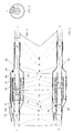
- FIG. 1 is a longitudinal section view of a cable joint according to the invention;
- FIG. 2 is the same longitudinal section view of the cable joint of FIG. 1 but rotated by an angle of 45°;
- FIG. 3 is a transversal view of the cable joint indicating the axis of the sections shown in the FIGs. 1 and 2;
- FIG. 4 is a detail view of the upper top portion of FIG. 1; and
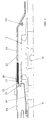
- FIG. 5 is a detail view of a variant implementation of the cable joint of FIG. 1.
-
- The longitudinal section of a cable joint linking two high voltage or power cables, generally indicated by the
referrals 1 and 2, is shown in FIGs. 1 and 2. The FIG. 1 represents a cable joint section along an axis A as indicated in FIG. 3, that is a transversal view of this cable joint, whilst the FIG. 2 represents a similar cable joint section but along an axis B, also indicated in FIG. 3. The cable joint includes ajunction body 3 wherein the terminus of thebared conductors 4 and 5 of the two single corehigh voltage cables 1 and 2 respectively are electrically connected to each other and re-insulated. Each of thesepower cables 1, 2 comprises aconductor 4, 5 surrounded by afirst insulation layer semi-conductive layer second insulation layer junction body 3 comprises aconnection part 12 adapted to electrically interconnect theconductors 4 and 5 of the cables and aninsulation box 13 covering theconnection part 12, the first insulation layers 6A, 7A and portions of thesemi-conductive layers junction body 3 as well as thepower cables 1 and 2 are all well known in the art and need thus not to be described in more detail hereafter. - The
metallic screen power cable 1, 2 is a water impervious layer that has to be continued along the joint. The cable joint is also used to earth the metallic screens of the power cables or to make cross-bonding on themetallic screens - To this end, at both ends of the
junction body 3, themetallic screens power cables 1 and 2 are bared over a predetermined length and each soldered over their whole circumference to a distinct end of a metallic member having the shape of a tube. This metallic tube has a central cylindrical part surrounding the junction body and narrowed ends. It is a watertight box that forms a shield protecting thejunction body 3. The metallic tube has two-parts electrically separated by ashield break 17, this shield break being preferably located in the cylindrical part of the tube. Afirst part 14 of the tube, shown on the right in the FIGs. 1 and 2, is constituted by a right portion of the cylindrical part and by the right narrowed end of the tube. It covers the right end of thejunction body 3 as well as the end of the cable 1 until the soldering with themetallic screen 8. The diameter of thisfirst part 14 is relatively large over thejunction body 3 and is narrowed over the cable 1 since the outer diameter of this cable is smaller than that of the junction body. Thesecond part left portion 15 of the shielding metallic cylindrical part of the tube covering the left of thejunction body 3, and by anarrowed end 16 covering the end of thecable 2 at the left of thejunction body 3 until the soldering with themetallic screen 9. The assembly of the present metallic member consists in mechanically tightening thenarrowed end 16 to theportion 15 of the cylindrical part over the whole length of its circumference. This assembly provides also a good electrically contact between theend 16 and theportion 15 of the tube. - It is to be noted that, as will be described hereafter, the
left portion 15 of the cylindrical part, theshield break 17 and thefirst part 14 of the metallic member or tube are rigidly assembled prior to be used in the field. - As already mentioned, the
left portion 15 of the cylindrical part of the shield faces the right portion of this cylindrical part but is insulated therefrom by ashield break 17. In more detail, the twocylindrical portions pre-fabricated insulator 18 including theshield break 17. The right upper part of the cable joint and thus also theinsulator 18 are visible in more detail on the FIG. 4. Theinsulator 18 has the form of a ring with a lying-H shaped longitudinal cross-section in which branches are engaged, with a tight fit, the ends of theportions pre-fabricated insulator 18 and of its position, the interruption of the metallic screen caused by theshield break 17 in the cylindrical part thereof, is minimized to a length of less than 10 mm. - The inner side of the
first part 14 of the metallic shielding member is provided with aninternal terminal 19A to which aninsulated conductor 20 is connected. For reducing the overall volume of the shielding member, theinternal terminal 19A is preferably located on the inner surface of the first narrowedend 14 of the tube, in the volume available between the right end of thejunction body 3 and the right narrowing part of the tube. Theinsulated conductor 20 is used for the above mentioned earthing or cross-bonding connections. It has one end connected to theinternal terminal 19A, runs between thejunction body 3 and the cylindrical part, and exits the watertight metallic member via anopening 21 in the second narrowedend 16 of the tube where itssecond end 19B is accessible, as shown in FIG. 1. Thisend 19B is thus electrically in contact with themetallic screen 8 of the power cable 1 via theinsulated conductor 20, theinternal terminal 19A and thefirst part 14 tubular shield. Thenarrowed end 16 of the second part of the tubular shield is provided with anexternal terminal 22, visible in FIG. 2. Thisexternal terminal 22 is thus in electrical contact with themetallic screen 9 of thepower cable 2 via thesecond part 16 of the metallic member. - Although two distinct cables, connected to the
end 19B of theinsulated conductor 20 and to theexternal terminal 22, may be used to perform cross-bonding, a coaxial cable is generally preferred. This is possible because the twoshield connections end 19B, whilst the screening of the coaxial cable is connected to the terminal 22. - The watertight
metallic member insulation coating 23 ending, at the left side of the member, with asmall polyester box 24 filled with resin. Thebox 24 more particularly covers the second narrowedend 16 of the tube and partially thesecond portion 15 of the cylindrical part. It also covers theinsulated conductor 20 at the outside of the metallic member. - As shown on FIG. 4, and in order to provide a good electrical stress control, a
layer 25 of material with a high dielectric constant is put around theinsulated conductor 20, especially on the portion of the insulated conductor that passes along theshield break 17. On this portion also anadditional insulation sleeve 26 is preferably provided around thejunction body 3. - In the above example of implementation, the
shield break 17 is located at the right side of thecable joint 3, out of the area of theconnection part 12. This means that the main part of thejunction body 3 is covered by thesecond portion 15 of the cylindrical part of the metallic member. In a variant of this implementation, as shown on FIG. 5, theshield break 17 is located at the other side, i.e. at the very left side, of thecable joint 3. The length of thesecond portion 15 of the cylindrical part of the shield is then reduced to zero, whilst the first portion of the cylindrical part covers the main part of thejunction body 3. Such a structure is generally more rigid than the previous one. - While the principles of the invention have been described above in connection with specific apparatus, it is to be clearly understood that this description is made only by way of example and not as a limitation on the scope of the invention, as defined in the appended claims.
Claims (10)
- Cable joint for connecting power cables (1, 2), each cable having a conductor (4, 5) successively surrounded by a first insulation layer (6A, 7A), a semi-conductive layer (6B, 7B), a metallic screen (8, 9), and a second insulation layer (10, 11),
said cable joint comprising a junction body (3) comprising connection means (12) adapted to connect bared portions of conductor ends together, and first insulation means (13), adapted to surround said connection means (12),
said joint further including a metallic member (14; 15, 16) forming a shield over the junction body (3), and second insulation means (23, 24) covering said metallic member as well as being adapted to cover end portions of the second insulation layer (10, 11) of the power cables,
said metallic member having at least two parts (14; 15, 16) electrically separated by a shield break (17) and each provided with a terminal (19A, 22) adapted to be electrically coupled to the metallic screen (8, 9) of a distinct one of said power cables (1, 2),
characterized in that at least one of said terminals (19A, 22) is an internal terminal (19A) located at the inner side of said metallic member (14; 15, 16) and is adapted to be connected to one end of an insulated conductor (20) located inside said metallic member and of which the other end (19B) is adapted to extend outside said metallic member. - Cable joint according to claim 1, characterized in that said metallic member (14; 15, 16) has the shape of a tube having a cylindrical part narrowed at each end of the junction body (3), said shield break (17) being provided in said cylindrical part, andin that said internal terminal (19A) is connected to a first part (14) of said metallic member and is located between a first narrowed end of said tube and a corresponding first end of the junction body.
- Cable joint according to claim 2, characterized in that the terminal connected to the second part (15, 16) of said metallic member (14; 15, 16) is an external terminal (22) located at the second narrowed end (16) of said tube,in that said first (14) and second (15, 16) parts of said metallic member form together a watertight box surrounding said junction body (3), andin that said other end (19B) of the insulated conductor (20) extends through an opening (21) provided in the second part (15, 16) of said member, near to said external terminal (22).
- Cable joint according to claim 3, characterized in that said second part (15, 16) of the metallic member (14; 15, 16) comprises said second narrowed end (16) and a portion (15) of the cylindrical part of said tube between said second narrowed end and said shield break (17), andin that said second narrowed end (16) has said external terminal (22) and said opening (21).
- Cable joint according to claim 4, characterized in that said portion (15) of the cylindrical part of said tube and belonging to said second part (15, 16) of the metallic member (14; 15, 16), said shield break (17) and the first part (14) of said metallic member including the remaining cylindrical part of said tube and said first narrowed end are rigidly assembled, andin that said second narrowed end (16) is mechanically tightened to this rigid assembly.
- Cable joint according to claim 5, characterized in that a pre-fabricated insulator (18) is provided at said shield break (17), and in that the facing ends of the two cylindrical parts of said tube are mechanically tightened to said insulator.
- Cable joint according to claim 1, characterized in that a layer of material (25) having a relatively high dielectric constant surrounds said insulated conductor (20) in the area of said shield break (17).
- Cable joint according to claim 3, characterized in that said other end (19B) of the insulated conductor (20) is connected to the central conductor of a coaxial cable of which the screening is connected to said external terminal (22), said coaxial cable being used for earthing or for cross-bonding connections.
- Cable joint according to claim 3, characterized in that said watertight box is filled with glass pellets.
- Cable joint according to claim 3, characterized in that said second insulation means (23, 24) includes a polyester box (24) filled with resin.
Priority Applications (4)
| Application Number | Priority Date | Filing Date | Title |
|---|---|---|---|
| DE69711055T DE69711055T2 (en) | 1997-11-28 | 1997-11-28 | Cable connection with earth connection and / or shield crossover for energy cabl |
| EP97402882A EP0920101B1 (en) | 1997-11-28 | 1997-11-28 | Cable joint with earthing connection and/or screen cross-bonding for power cables |
| JP10308888A JPH11205987A (en) | 1997-11-28 | 1998-10-29 | Cable joint with grounding connection and/or screen cross-bonding for power cable |
| US09/195,436 US6040527A (en) | 1997-11-28 | 1998-11-18 | Cable joint with grounding connection and/or screen cross-bonding for power cables |
Applications Claiming Priority (1)
| Application Number | Priority Date | Filing Date | Title |
|---|---|---|---|
| EP97402882A EP0920101B1 (en) | 1997-11-28 | 1997-11-28 | Cable joint with earthing connection and/or screen cross-bonding for power cables |
Publications (2)
| Publication Number | Publication Date |
|---|---|
| EP0920101A1 EP0920101A1 (en) | 1999-06-02 |
| EP0920101B1 true EP0920101B1 (en) | 2002-03-13 |
Family
ID=8229915
Family Applications (1)
| Application Number | Title | Priority Date | Filing Date |
|---|---|---|---|
| EP97402882A Expired - Lifetime EP0920101B1 (en) | 1997-11-28 | 1997-11-28 | Cable joint with earthing connection and/or screen cross-bonding for power cables |
Country Status (4)
| Country | Link |
|---|---|
| US (1) | US6040527A (en) |
| EP (1) | EP0920101B1 (en) |
| JP (1) | JPH11205987A (en) |
| DE (1) | DE69711055T2 (en) |
Families Citing this family (19)
| Publication number | Priority date | Publication date | Assignee | Title |
|---|---|---|---|---|
| KR101135143B1 (en) | 2004-03-01 | 2012-04-16 | 후루카와 덴키 고교 가부시키가이샤 | Cable connecting structure |
| WO2007074480A1 (en) * | 2005-12-28 | 2007-07-05 | Prysmian Cavi E Sistemi Energia S.R.L. | Joining method and related junction for electric cables, tubular covering sleeve for electric-cable junctions and process for manufacturing the same |
| JP2007259623A (en) * | 2006-03-24 | 2007-10-04 | Three M Innovative Properties Co | Mold spacer for electric wire, connection kit for electric wire, and manufacturing method for electric wire, and electric wire |
| EP2088657A1 (en) * | 2008-02-08 | 2009-08-12 | ABB Technology AG | A method of producing a cable casing, a cable casing and a cable joint arrangement provided therewith |
| EP2088656A1 (en) * | 2008-02-08 | 2009-08-12 | ABB Technology AG | A cable joint arrangement |
| FR2977396B1 (en) * | 2011-07-01 | 2013-07-05 | Nexans | ELECTRIC LINE PROVIDED WITH JUNCTIONS WITH SCREEN ARRESTS |
| JP5776123B2 (en) * | 2012-08-20 | 2015-09-09 | 株式会社ビスキャス | Power cable connection structure and insulation member |
| JP5761535B2 (en) * | 2013-02-12 | 2015-08-12 | 株式会社ビスキャス | Power cable connection structure and insulation member |
| CN103986112B (en) * | 2013-02-12 | 2017-03-01 | 株式会社维世佳 | The connecting structure of power cable and insulating element |
| JP6282870B2 (en) * | 2014-01-30 | 2018-02-21 | 昭和電線ケーブルシステム株式会社 | Intermediate connection of protective tube and power cable |
| TWI574285B (en) * | 2014-03-14 | 2017-03-11 | 吳俊宏 | Continuable waterproof cable structure, continuable waterproof power module and waterproof terminal assembly |
| US9504195B2 (en) | 2014-05-16 | 2016-11-22 | Tyco Electronics Corporation | Cover assemblies, kits and methods for covering electrical cables and connections |
| JP2016010202A (en) * | 2014-06-23 | 2016-01-18 | 株式会社ビスキャス | Power cable connection part and anticorrosive cover |
| CN104868435A (en) * | 2015-06-02 | 2015-08-26 | 张维秀 | Sealing joint for transfer between cable and signal cable and manufacturing method thereof |
| EP3104463B1 (en) * | 2015-06-12 | 2020-11-11 | Siemens Aktiengesellschaft | Subsea connector |
| WO2018098166A1 (en) | 2016-11-22 | 2018-05-31 | Te Connectivity Corporation | Cover assemblies for cables and electrical connections and pre-expanded units and methods including same |
| CN107632203B (en) * | 2017-08-14 | 2019-09-03 | 国网湖南省电力公司 | A kind of large ground network earth loop impedance test method that consideration the earth influences |
| US20220224088A1 (en) * | 2019-05-01 | 2022-07-14 | Brugg Kabel Ag | Repair and replacement of high voltage cables and joints |
| CN112670911B (en) * | 2020-12-23 | 2023-01-03 | 长园电力技术有限公司 | Connecting method and connecting structure of aluminum sheath cable and metal pipe |
Family Cites Families (8)
| Publication number | Priority date | Publication date | Assignee | Title |
|---|---|---|---|---|
| US28837A (en) * | 1860-06-26 | Fog-alarm | ||
| GB1059270A (en) * | 1964-10-23 | 1967-02-15 | British Insulated Callenders | Improvements in joints for electric cables |
| US4032205A (en) * | 1976-09-10 | 1977-06-28 | Rte Corporation | Adaptor for a high voltage cable |
| US4234756A (en) * | 1979-03-29 | 1980-11-18 | Reliable Electric Company | Preterminated block system and method of installing same |
| FI69943C (en) * | 1979-07-10 | 1986-05-26 | Sumitomo Electric Industries | FOERFARANDE FOER BILDANDE AV EN FOERBINDNING FOER EN POLYOLEFINISOLERAD ELEKTRISK LEDNING ELLER KABEL OCH VAERMEKRYMPANDE SLANG FOER GENOMFOERANDE AV FOERFARANDET |
| FR2593335B1 (en) * | 1986-01-22 | 1988-07-22 | Pirelli Treficable | DEVICE FOR CONNECTING TWO INSULATED ELECTRICAL CABLES INCLUDING IMPROVED EXTERNAL JUNCTION PROTECTION MEANS |
| DE4102114C2 (en) * | 1991-01-25 | 1994-01-20 | Rheydt Kabelwerk Ag | Process for the cyclical crossing of cable sheaths |
| DE9415782U1 (en) * | 1994-09-23 | 1996-01-25 | Siemens Ag | Plastic-insulated high-voltage cable system with screen separation points |
-
1997
- 1997-11-28 EP EP97402882A patent/EP0920101B1/en not_active Expired - Lifetime
- 1997-11-28 DE DE69711055T patent/DE69711055T2/en not_active Expired - Fee Related
-
1998
- 1998-10-29 JP JP10308888A patent/JPH11205987A/en not_active Withdrawn
- 1998-11-18 US US09/195,436 patent/US6040527A/en not_active Expired - Fee Related
Also Published As
| Publication number | Publication date |
|---|---|
| DE69711055T2 (en) | 2002-09-12 |
| JPH11205987A (en) | 1999-07-30 |
| US6040527A (en) | 2000-03-21 |
| EP0920101A1 (en) | 1999-06-02 |
| DE69711055D1 (en) | 2002-04-18 |
Similar Documents
| Publication | Publication Date | Title |
|---|---|---|
| EP0920101B1 (en) | Cable joint with earthing connection and/or screen cross-bonding for power cables | |
| EP0920102B1 (en) | Outer protection with shield-break for high-voltage cable joint | |
| US3307137A (en) | Conductor termination | |
| US20070137881A1 (en) | Terminal structure of multiphase superconducting cable | |
| KR100394929B1 (en) | Junction of power cables | |
| JP3769046B2 (en) | Electric cable terminal | |
| US4424410A (en) | Splice connector with shield break | |
| US5646370A (en) | Permanent attachment of grounding wire | |
| US6172304B1 (en) | Device for providing leakproof protection to a splice in a high voltage cable | |
| CA1117198A (en) | Splice connector housing with shield break | |
| US3792191A (en) | Enclosure for conductor of electrical transmission system | |
| EP2088657A1 (en) | A method of producing a cable casing, a cable casing and a cable joint arrangement provided therewith | |
| US4638112A (en) | Stop joint for interconnecting two electrical cables of different types | |
| JP3601991B2 (en) | Termination connection for ground | |
| KR940002352Y1 (en) | Cable connector | |
| JP3006333B2 (en) | Termination connection for power cable with built-in optical fiber unit | |
| JPH04255682A (en) | Shielding cable and terminal structure therefor | |
| EP2710683B1 (en) | Dead front cable terminal with isolated shield | |
| JPH0323791Y2 (en) | ||
| JP2532266Y2 (en) | Power cable prefabricated connection | |
| JPS6015392Y2 (en) | Solderless connection of power cable with water barrier layer | |
| JPH09224325A (en) | Power cable connection part | |
| CN113659494A (en) | Preparation process of 10-35kV welding type cross-linked cable terminal | |
| JPH11205989A (en) | External terminating device of power cable | |
| CA1094181A (en) | Electrical cable joint casing |
Legal Events
| Date | Code | Title | Description |
|---|---|---|---|
| PUAI | Public reference made under article 153(3) epc to a published international application that has entered the european phase |
Free format text: ORIGINAL CODE: 0009012 |
|
| AK | Designated contracting states |
Kind code of ref document: A1 Designated state(s): BE DE ES FR GB IT SE |
|
| AX | Request for extension of the european patent |
Free format text: AL;LT;LV;MK;RO;SI |
|
| 17P | Request for examination filed |
Effective date: 19991202 |
|
| AKX | Designation fees paid |
Free format text: BE DE ES FR GB IT SE |
|
| 17Q | First examination report despatched |
Effective date: 20000317 |
|
| GRAG | Despatch of communication of intention to grant |
Free format text: ORIGINAL CODE: EPIDOS AGRA |
|
| GRAH | Despatch of communication of intention to grant a patent |
Free format text: ORIGINAL CODE: EPIDOS IGRA |
|
| RAP1 | Party data changed (applicant data changed or rights of an application transferred) |
Owner name: NEXANS |
|
| GRAH | Despatch of communication of intention to grant a patent |
Free format text: ORIGINAL CODE: EPIDOS IGRA |
|
| REG | Reference to a national code |
Ref country code: GB Ref legal event code: IF02 |
|
| GRAA | (expected) grant |
Free format text: ORIGINAL CODE: 0009210 |
|
| AK | Designated contracting states |
Kind code of ref document: B1 Designated state(s): BE DE ES FR GB IT SE Kind code of ref document: B1 Designated state(s): BE CH DE FR IT LI NL SE |
|
| REF | Corresponds to: |
Ref document number: 69711055 Country of ref document: DE Date of ref document: 20020418 |
|
| REG | Reference to a national code |
Ref country code: CH Ref legal event code: NV Representative=s name: CABINET ROLAND NITHARDT CONSEILS EN PROPRIETE INDU Ref country code: CH Ref legal event code: EP |
|
| RBV | Designated contracting states (corrected) |
Designated state(s): BE CH DE FR IT LI NL SE |
|
| ET | Fr: translation filed | ||
| PGFP | Annual fee paid to national office [announced via postgrant information from national office to epo] |
Ref country code: SE Payment date: 20021106 Year of fee payment: 6 |
|
| PGFP | Annual fee paid to national office [announced via postgrant information from national office to epo] |
Ref country code: FR Payment date: 20021108 Year of fee payment: 6 |
|
| PGFP | Annual fee paid to national office [announced via postgrant information from national office to epo] |
Ref country code: DE Payment date: 20021128 Year of fee payment: 6 |
|
| PGFP | Annual fee paid to national office [announced via postgrant information from national office to epo] |
Ref country code: NL Payment date: 20021129 Year of fee payment: 6 Ref country code: CH Payment date: 20021129 Year of fee payment: 6 |
|
| PLBE | No opposition filed within time limit |
Free format text: ORIGINAL CODE: 0009261 |
|
| STAA | Information on the status of an ep patent application or granted ep patent |
Free format text: STATUS: NO OPPOSITION FILED WITHIN TIME LIMIT |
|
| PGFP | Annual fee paid to national office [announced via postgrant information from national office to epo] |
Ref country code: BE Payment date: 20030121 Year of fee payment: 6 |
|
| 26N | No opposition filed |
Effective date: 20021216 |
|
| PG25 | Lapsed in a contracting state [announced via postgrant information from national office to epo] |
Ref country code: SE Free format text: LAPSE BECAUSE OF NON-PAYMENT OF DUE FEES Effective date: 20031129 |
|
| PG25 | Lapsed in a contracting state [announced via postgrant information from national office to epo] |
Ref country code: LI Free format text: LAPSE BECAUSE OF NON-PAYMENT OF DUE FEES Effective date: 20031130 Ref country code: CH Free format text: LAPSE BECAUSE OF NON-PAYMENT OF DUE FEES Effective date: 20031130 Ref country code: BE Free format text: LAPSE BECAUSE OF NON-PAYMENT OF DUE FEES Effective date: 20031130 |
|
| BERE | Be: lapsed |
Owner name: *NEXANS Effective date: 20031130 |
|
| PG25 | Lapsed in a contracting state [announced via postgrant information from national office to epo] |
Ref country code: NL Free format text: LAPSE BECAUSE OF NON-PAYMENT OF DUE FEES Effective date: 20040601 |
|
| PG25 | Lapsed in a contracting state [announced via postgrant information from national office to epo] |
Ref country code: DE Free format text: LAPSE BECAUSE OF NON-PAYMENT OF DUE FEES Effective date: 20040602 |
|
| EUG | Se: european patent has lapsed | ||
| REG | Reference to a national code |
Ref country code: CH Ref legal event code: PL |
|
| PG25 | Lapsed in a contracting state [announced via postgrant information from national office to epo] |
Ref country code: FR Free format text: LAPSE BECAUSE OF NON-PAYMENT OF DUE FEES Effective date: 20040730 |
|
| NLV4 | Nl: lapsed or anulled due to non-payment of the annual fee |
Effective date: 20040601 |
|
| REG | Reference to a national code |
Ref country code: FR Ref legal event code: ST |
|
| PG25 | Lapsed in a contracting state [announced via postgrant information from national office to epo] |
Ref country code: IT Free format text: LAPSE BECAUSE OF NON-PAYMENT OF DUE FEES;WARNING: LAPSES OF ITALIAN PATENTS WITH EFFECTIVE DATE BEFORE 2007 MAY HAVE OCCURRED AT ANY TIME BEFORE 2007. THE CORRECT EFFECTIVE DATE MAY BE DIFFERENT FROM THE ONE RECORDED. Effective date: 20051128 |