EP3545190B1 - Verfahren zur steuerung einer windturbine, steuergerät für eine windturbine sowie windturbine - Google Patents
Verfahren zur steuerung einer windturbine, steuergerät für eine windturbine sowie windturbine Download PDFInfo
- Publication number
- EP3545190B1 EP3545190B1 EP17800382.8A EP17800382A EP3545190B1 EP 3545190 B1 EP3545190 B1 EP 3545190B1 EP 17800382 A EP17800382 A EP 17800382A EP 3545190 B1 EP3545190 B1 EP 3545190B1
- Authority
- EP
- European Patent Office
- Prior art keywords
- wind turbine
- frequency
- wind
- reduction
- wind turbines
- Prior art date
- Legal status (The legal status is an assumption and is not a legal conclusion. Google has not performed a legal analysis and makes no representation as to the accuracy of the status listed.)
- Active
Links
Images


Classifications
-
- F—MECHANICAL ENGINEERING; LIGHTING; HEATING; WEAPONS; BLASTING
- F03—MACHINES OR ENGINES FOR LIQUIDS; WIND, SPRING, OR WEIGHT MOTORS; PRODUCING MECHANICAL POWER OR A REACTIVE PROPULSIVE THRUST, NOT OTHERWISE PROVIDED FOR
- F03D—WIND MOTORS
- F03D7/00—Controlling wind motors
- F03D7/02—Controlling wind motors the wind motors having rotation axis substantially parallel to the air flow entering the rotor
- F03D7/04—Automatic control; Regulation
- F03D7/042—Automatic control; Regulation by means of an electrical or electronic controller
- F03D7/048—Automatic control; Regulation by means of an electrical or electronic controller controlling wind farms
-
- F—MECHANICAL ENGINEERING; LIGHTING; HEATING; WEAPONS; BLASTING
- F03—MACHINES OR ENGINES FOR LIQUIDS; WIND, SPRING, OR WEIGHT MOTORS; PRODUCING MECHANICAL POWER OR A REACTIVE PROPULSIVE THRUST, NOT OTHERWISE PROVIDED FOR
- F03D—WIND MOTORS
- F03D7/00—Controlling wind motors
- F03D7/02—Controlling wind motors the wind motors having rotation axis substantially parallel to the air flow entering the rotor
- F03D7/028—Controlling wind motors the wind motors having rotation axis substantially parallel to the air flow entering the rotor controlling wind motor output power
- F03D7/0284—Controlling wind motors the wind motors having rotation axis substantially parallel to the air flow entering the rotor controlling wind motor output power in relation to the state of the electric grid
-
- G—PHYSICS
- G05—CONTROLLING; REGULATING
- G05B—CONTROL OR REGULATING SYSTEMS IN GENERAL; FUNCTIONAL ELEMENTS OF SUCH SYSTEMS; MONITORING OR TESTING ARRANGEMENTS FOR SUCH SYSTEMS OR ELEMENTS
- G05B15/00—Systems controlled by a computer
- G05B15/02—Systems controlled by a computer electric
-
- H—ELECTRICITY
- H02—GENERATION; CONVERSION OR DISTRIBUTION OF ELECTRIC POWER
- H02J—ELECTRIC POWER NETWORKS; CIRCUIT ARRANGEMENTS OR SYSTEMS FOR SUPPLYING OR DISTRIBUTING ELECTRIC POWER; SYSTEMS FOR STORING ELECTRIC ENERGY
- H02J3/00—Circuit arrangements for AC mains or AC distribution networks
- H02J3/38—Arrangements for feeding a single network from two or more generators or sources in parallel; Arrangements for feeding already energised networks from additional generators or sources in parallel
- H02J3/381—Dispersed generators
-
- H—ELECTRICITY
- H02—GENERATION; CONVERSION OR DISTRIBUTION OF ELECTRIC POWER
- H02J—ELECTRIC POWER NETWORKS; CIRCUIT ARRANGEMENTS OR SYSTEMS FOR SUPPLYING OR DISTRIBUTING ELECTRIC POWER; SYSTEMS FOR STORING ELECTRIC ENERGY
- H02J3/00—Circuit arrangements for AC mains or AC distribution networks
- H02J3/38—Arrangements for feeding a single network from two or more generators or sources in parallel; Arrangements for feeding already energised networks from additional generators or sources in parallel
- H02J3/46—Controlling the sharing of generated power between the generators, sources or networks
- H02J3/48—Controlling the sharing of active power
-
- F—MECHANICAL ENGINEERING; LIGHTING; HEATING; WEAPONS; BLASTING
- F05—INDEXING SCHEMES RELATING TO ENGINES OR PUMPS IN VARIOUS SUBCLASSES OF CLASSES F01-F04
- F05B—INDEXING SCHEME RELATING TO WIND, SPRING, WEIGHT, INERTIA OR LIKE MOTORS, TO MACHINES OR ENGINES FOR LIQUIDS COVERED BY SUBCLASSES F03B, F03D AND F03G
- F05B2270/00—Control
- F05B2270/30—Control parameters, e.g. input parameters
- F05B2270/337—Electrical grid status parameters, e.g. voltage, frequency or power demand
-
- H—ELECTRICITY
- H02—GENERATION; CONVERSION OR DISTRIBUTION OF ELECTRIC POWER
- H02J—ELECTRIC POWER NETWORKS; CIRCUIT ARRANGEMENTS OR SYSTEMS FOR SUPPLYING OR DISTRIBUTING ELECTRIC POWER; SYSTEMS FOR STORING ELECTRIC ENERGY
- H02J2101/00—Supply or distribution of decentralised, dispersed or local electric power generation
- H02J2101/20—Dispersed power generation using renewable energy sources
- H02J2101/28—Wind energy
-
- Y—GENERAL TAGGING OF NEW TECHNOLOGICAL DEVELOPMENTS; GENERAL TAGGING OF CROSS-SECTIONAL TECHNOLOGIES SPANNING OVER SEVERAL SECTIONS OF THE IPC; TECHNICAL SUBJECTS COVERED BY FORMER USPC CROSS-REFERENCE ART COLLECTIONS [XRACs] AND DIGESTS
- Y02—TECHNOLOGIES OR APPLICATIONS FOR MITIGATION OR ADAPTATION AGAINST CLIMATE CHANGE
- Y02E—REDUCTION OF GREENHOUSE GAS [GHG] EMISSIONS, RELATED TO ENERGY GENERATION, TRANSMISSION OR DISTRIBUTION
- Y02E10/00—Energy generation through renewable energy sources
- Y02E10/70—Wind energy
- Y02E10/72—Wind turbines with rotation axis in wind direction
-
- Y—GENERAL TAGGING OF NEW TECHNOLOGICAL DEVELOPMENTS; GENERAL TAGGING OF CROSS-SECTIONAL TECHNOLOGIES SPANNING OVER SEVERAL SECTIONS OF THE IPC; TECHNICAL SUBJECTS COVERED BY FORMER USPC CROSS-REFERENCE ART COLLECTIONS [XRACs] AND DIGESTS
- Y02—TECHNOLOGIES OR APPLICATIONS FOR MITIGATION OR ADAPTATION AGAINST CLIMATE CHANGE
- Y02E—REDUCTION OF GREENHOUSE GAS [GHG] EMISSIONS, RELATED TO ENERGY GENERATION, TRANSMISSION OR DISTRIBUTION
- Y02E10/00—Energy generation through renewable energy sources
- Y02E10/70—Wind energy
- Y02E10/76—Power conversion electric or electronic aspects
Definitions
- the invention relates to a wind turbine controller, a method for controlling a wind turbine and a cluster of wind turbines connected to a utility grid.
- a utility grid connects a number of power generators and consumers.
- the utility grid seeks to maintain a rated frequency, e.g. of 50 or 60 Hz when the generated power balance the consumed power.
- the frequency of the utility grid may rise if the consumed power suddenly drops and creates an unbalance between the generated and consumed power. Deviation from the rated frequency may potentially affect the function of electrical equipment connected to the utility grid and is therefore undesired.
- the consumption or the production may be amended.
- An increased frequency may be counteracted by reduced production.
- the balance is generally established by disconnecting one or more turbines from the utility grid.
- EP 2 082 132 81 examples of prior art can be found in EP 2 082 132 81 , EP 2 884 096 A1 and US 2011/012352 A1 .
- a method according to claim 1 for controlling individually wind turbines in a cluster of wind turbines, where each wind turbine of the cluster of wind turbines is configured to deliver power to the same utility grid having a rated frequency, the method comprising the steps of:
- a wind turbine controller configured to control a wind turbine in a cluster of wind turbines, the controller being configured to control in accordance with the method of the first aspect.
- a wind turbine with a controller according to the second aspect is provided.
- the control becomes very fast and the ability to counteract unbalance is improved.
- the wind turbine operation for the first wind turbine is not completely terminated whereby the turbine can quickly return to normal operation when the frequency of the grid is recovered. This is advantageous compared to shutting down turbines which requires a slow start up procedure.
- the continued operation potentially reduces stress and wear on the wind turbine compared to a complete shut down.
- the reduction provides a reduced power level which is not dependent of the grid frequency.
- the grid frequency specifies when to provide the reduction but not necessarily to which level the reduction reduces the power.
- the levels to which the power is reduced may be fixed levels or optionally levels depending on wind speed, but not on frequency.
- the cluster may e.g. be a wind park, a part of a wind park, or several wind parks with a plurality of wind turbines located close to each other, or the cluster may be a plurality of wind turbines spread widely in a utility grid.
- the method may include the step of continuously surveying the utility grid. The surveying could be located directly at the point where the wind turbine(s) connect to the utility grid or it could be distant from the wind turbine(s).
- the surveying establishes the change in frequency. Once the frequency reaches a first threshold, the first reduction is provided for the first wind turbine.
- the rated frequency is 50 Hz
- the first threshold is 51 Hz
- the present power level is 2 MW, e.g. corresponding t a rated power level for the wind turbine
- the first reduced power level is 1 MW.
- the first reduction reduces the delivery from 2 MW to 1 MW upon reaching a frequency of 51 Hz.
- the first reduction counteracts the imbalance and depending on the consumption, the first reduction may have the impact that the frequency is lowered.
- the first wind turbine continues to deliver power at the first reduced level. This situation may continue e.g. until the grid frequency reverts to a satisfactory level, e.g. until it passes a reinstating level which is typically lower than the first threshold value thereby creating a hysteresis ensuring a stable control.
- the hysteresis may e.g. be in the range of 0.2-1 pct. of the rated frequency, which for a 50 Hz grid frequency means that the reinstating level is 0.1-0.5 Hz lower than the threshold.
- the method further comprises the step of providing, at a second point in time, t2, a second reduction by which delivery from a second wind turbine in the cluster of wind turbines is reduced from a present power level to a second reduced power level.
- t2 is later than t1, and the second reduction is thereby shifted in time relative to the first reduction. Due to the shift in time, the first and second wind turbines are de-rated at different points in time, and the impact in the utility grid becomes smoother. This again enables a more precise and dampened control system with less fluctuations and distortion and a faster reacting control for the same gain.
- the shift in time could be caused by a timer, or the second reduction may be provided in response to the frequency of the utility grid exceeding a second threshold value.
- the second threshold is different from the first threshold, whereby the shift in time is obtained by the time it takes for the grid frequency to change from the first to the second threshold which again depends on the balance between consumption and production. This would have the advantage that the second reduction takes into account the effect of the first reduction.
- the wind turbines in the cluster may operate autonomously and yet each contribute to a common control strategy which both counteract unbalance in the frequency and prevents large abrupt changes to the power production. This can be carried out without any communication between the autonomous wind turbines since each wind turbine may reach on its own threshold pre-defined in the controller of the wind turbine.
- the first and second reduced power levels could be different or they could be identical.
- Identical reduced power levels are simple and provide an easy measure for prediction of the impact when calculating with many wind turbines in a large cluster. On the other hand, it may be an advantage to de-rate different wind turbines differently, e.g. if they are in different wind conditions or if they have different rated, nominal, power output.
- the wind turbines have a minimum power output, and the first and/or the second reduced power is the minimum power output for the first or second wind turbine, respectively.
- the minimum power output typically depends on the wind speed.
- the first and/or the second reduced power is a fixed value which does not depend on wind or other factors, and it could e.g. be specified based on the minimum power output for a given wind speed.
- the reduction may also be determined as a percentage of a reference production.
- the present power production may form this reference point such that the present production is reduced by a factor, e.g. by 25 pct.
- the un-curtailed production may alternatively form the reference point, e.g. such that the production is reduced by a factor of 25 pct. relative to the nominal power production of the turbine in question.
- At least one of the first reduced power level, the second reduced power level, or the third reduced power level could be ramp rate limited which means that the change from one power level to another power level is carried out in successive small steps until the new power level is achieved.
- At least one of the first reduced power level, the second reduced power level, or a third reduced power level may be determined based on a wind speed. This may e.g. be a stepwise adaption of reduced power level for different ranges of wind speed, or it could be a continuous adaption of the level of the reduced power depending on the actual wind speed.
- the first reduced power level may have one relatively low value for wind speeds up to 15 m/s and a higher reduced power level for wind speeds above 15 m/s. In that way, a higher counterforce from the generator on the drive train is provided for higher wind speed which may support balance in the drive train during high wind speeds.
- the first reduced power level is a result of a function including the wind speed.
- This function could e.g. be: a z + x ⁇ v where a is a present power level provided by the wind turbine, z and x are constants and v is the wind speed.
- a further step of providing at a third point in time, t3, at least one further reduction by which delivery from the first or second wind turbine is reduced to a third power level may be introduced.
- each of the wind turbines in the cluster may be de-rated sequentially to several different levels of power.
- the first wind turbine is reduced to the first power level upon exceeding a first threshold value of the frequency, and subsequently to a third, lower, power level, e.g. in response to the first threshold value continuously being exceeded or in response to a third threshold for the frequency being subsequently exceeded.
- the method may further comprise the step of, at the first point in time, t1, delivering power from at least one other wind turbine without introducing corrections based on the frequency of the utility grid.
- one or more of the wind turbines of the utility grid may be reduced completely independently on the operation of other wind turbines of the utility grid. I.e. the other wind turbines may continue operation completely unaffected by the reduction carried out for one or more of the affected wind turbines of the cluster.
- the method may comprise the further step of providing, at a fourth point in time, t4, a first increase by which delivery from at least one of the first and second wind turbines is increased, the first increase being provided in response to the frequency of the utility grid surpassing the first threshold value.
- each wind turbine for which a reduction is provided may return to normal operation once the balance is re-established and a desired frequency, e.g. the rated frequency, is achieved.
- the normal power production may be re-established stepwise to avoid abrupt increases in the power production.
- the method is until now described relative to a first and a second wind turbine of the cluster of wind turbines.
- the method may apply to any number of wind turbines in the cluster, i.e. a first, a second, a third, a fourth, a fifth etc. wind turbine, and particularly, each wind turbine may be associated with a unique threshold value for the frequency at which a reduction for that wind turbine is provided. In that way, all wind turbines in the cluster becomes unique and self-controlling, and at the same time, very large and sudden changes are avoided since each wind turbine reacts on different thresholds.
- a controller for controlling operation of at least two wind turbines in a cluster of wind turbines is provided.
- the controller is configured to control each of the two wind turbines individually and in accordance with the method of the first aspect described above.
- the controller may particularly be installed locally in each wind turbine, at it may particularly be configured to operate autonomously.
- the controller of each wind turbine or for a group of wind turbines in the cluster of wind turbines may include controllers with one pre-stored threshold for the frequency at which the reduction is provided.
- the controllers may be joined in a communication network e.g. including a central server controller which controls all wind turbines or selected wind turbines of the cluster.
- a wind turbine in a cluster of wind turbines includes a controller according to the second aspect, e.g. a controller with a pre-stored threshold value for the frequency at which the wind turbine is considered to reduce the power level.
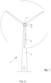
- Fig. 1 illustrates a modern wind turbine 1 with a tower 2 and a wind turbine nacelle 3 positioned on top of the tower.
- the wind turbine rotor comprising at least one blade such as three wind turbine blades 5 as illustrated, is connected to the hub 4 through pitch mechanisms 6.
- Each pitch mechanism includes a blade bearing and pitch actuating means which allows the blade to pitch.
- the pitch process is controlled by a pitch controller.
- wind turbines 1 connected to a utility grid 7 contribute to frequency control during an event where the frequency of the utility grid increases. More specific the wind turbines 1 are required to reduce power generation when the frequency exceeds a predetermined level defined by grid operators.
- the reduction in power generation is done by providing reduction in power level for individual wind turbines.
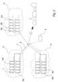
- Fig. 2 illustrates schematically a cluster of wind turbines 1, 10a, 10b,... 10x, 12 connected to a distributed utility grid 7.
- a number of wind turbines 1, 10a, 10b,... 10x, 12 must provide a reduction in power level.
- each individual wind turbine 12a, 12b,...12x in a cluster of wind turbines comprises a controller which is programmed to provide the reduction.
- the surveillance of the frequency of the utility grid may include the step of continuously comparing acquired information about grid frequency with a stored predefined frequency threshold value. This may be done for one, two, three or multiple wind turbines, but it is done individually for each wind turbine by the control means in said individual wind turbine 12a, 12b,... 12x.
- the controllers operate completely independently, and no communication from a central controller or from other wind turbines of the utility grid is necessary.
- Each controller is configured to provide a reduction by which delivery from the wind turbine is reduced from whatever power level is presently produced to a reduced power level. This reduction is triggered by a frequency of the utility grid exceeding a threshold value which is programmed into the controller.
- the controller survey the frequency of the utility grid, e.g. by receiving information from a separate sensor or by communicating with a switch gear or similar device connected between the wind turbine and the grid.
- the wind turbine controller triggers the reduction, the wind turbine is allowed to continue in operation while it produces a reduced power output to the utility grid. This allows the wind turbine to remain operational with heated lubrication oil and reinstatement of the wind turbine in normal, non-reduced power output can be carried out swiftly.
- controller and wind turbine may also be connected to a central control system. From this central system, the controller may receive control parameter including but not limited to:
- one central control means 9 could be connected to a plurality of wind turbines or all wind turbines of the cluster of wind turbines.
- Fig. 3 illustrates power/frequency relation for the controller. For frequencies below the threshold value no power reduction is imposed. For frequencies above the threshold value the power production is reduced, e.g. to technical minimum which is typical 10-25% of rated power for a wind turbine.
- the abscissa indicates the frequency and the ordinate indicates the wind turbine power (PU).
- 13 is a static power/frequency relation
- 14 is a frequency threshold
- 15 is a technical minimum power (PU) for the wind turbine.
- the controllers of different wind turbines may have different predefined and programmed frequency threshold values such that they do not reduce power simultaneously. For small frequency increases only few turbines will reduce power while all turbines will reduce power for larger frequency increases.
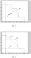
- Figs. 5 and 6 illustrate two examples of the resulting Power/frequency on plant level for a site with 3 turbines.
- the abscissa indicates the frequency and the ordinate indicates the wind turbine power (PU).
- 16 is a method according to this invention in the embodiment where each turbine performs a random selection of threshold value, 17 is an alternative, more complicated, continuous change in effect as a function of frequency, and 18 is a technical minimum power for the wind turbine.
- Fig. 7 and 8 illustrate two examples of the resulting Power/frequency on plant level for a site with 100 turbines.
- the abscissa indicates the frequency and the ordinate indicates the wind turbine power (PU).
- 16 is a method according to this invention in the embodiment where each turbine performs a random selection of threshold value, 17 is an alternative, more complicated, continuous change in effect as a function of frequency, and 18 is a technical minimum power for the wind turbine.
- c.f. graph no. 16 is close to the much more complicated continuous control principle illustrated by graph no. 17.
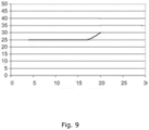
- Fig. 9 illustrates a ratio between wind speed and minimum power output.
- the power provided by the reduction is maintained above a minimum level and that this minimum level may depend on the wind speed.
- the abscissa indicates the wind speed and the ordinate indicates the minimum wind turbine power in percentage of a rated power for the wind turbine.
- the minimum power output increases.
Landscapes
- Engineering & Computer Science (AREA)
- Power Engineering (AREA)
- General Engineering & Computer Science (AREA)
- Combustion & Propulsion (AREA)
- Sustainable Energy (AREA)
- Chemical & Material Sciences (AREA)
- Sustainable Development (AREA)
- Mechanical Engineering (AREA)
- Life Sciences & Earth Sciences (AREA)
- Physics & Mathematics (AREA)
- General Physics & Mathematics (AREA)
- Automation & Control Theory (AREA)
- Wind Motors (AREA)
Claims (7)
- Verfahren zum Steuern von Windkraftanlagen in einer Gruppe von Windkraftanlagen, wobei jede Windkraftanlage einzeln gesteuert wird und wobei jede Windkraftanlage so konfiguriert ist, dass sie Leistung mit einer Nennfrequenz an dasselbe Energieversorgungsnetz abgibt, wobei das Verfahren die folgenden Schritte umfasst:- Bereitstellen, zu einem ersten Zeitpunkt, t1, einer ersten Reduzierung, um die Abgabe von einer ersten Windkraftanlage in der Gruppe von Windkraftanlagen von einem aktuellen Leistungsniveau auf ein erstes reduziertes Leistungsniveau reduziert wird, wobei die erste Reduzierung als Reaktion darauf bereitgestellt wird, dass eine Anfangsfrequenz des Energieversorgungsnetzes einen ersten Schwellenwert überschreitet; und- Fortsetzen der Abgabe von Leistung von der ersten Windkraftanlage auf dem ersten reduzierten Leistungsniveau, während die Anfangsfrequenz den ersten Schwellenwert überschreitet,- Bereitstellen, zu einem zweiten Zeitpunkt, t2, einer zweiten Reduzierung, um die Abgabe von einer zweiten Windkraftanlage in der Gruppe von Windkraftanlagen von einem aktuellen Leistungsniveau auf ein zweites reduziertes Leistungsniveau reduziert wird,wobei t2 später als t1 ist und die zweite Reduzierung dadurch zeitlich relativ zu der ersten Reduzierung verschoben ist, wobei die zweite Reduzierung als Reaktion darauf bereitgestellt wird, dass die Frequenz des Energieversorgungsnetzes einen zweiten Schwellenwert überschreitet, und wobei der erste und der zweite Schwellenwert unterschiedlich sind, wobei mindestens eine der ersten und der zweiten Reduzierung auf ein Leistungsniveau reduziert, das unabhängig von der Frequenz des Energieversorgungsnetzes ist,wobei das erste und zweite erste reduzierte Leistungsniveau eine technische Mindestleistung für die Windkraftanlage ist.
- Verfahren nach Anspruch 1, weiter umfassend den Schritt von- Bereitstellen, zu einem dritten Zeitpunkt, t3, mindestens einer weiteren Reduzierung, um die Abgabe der ersten oder der zweiten Windkraftanlage auf ein drittes Leistungsniveau reduziert wird.
- Verfahren nach einem der vorstehenden Ansprüche, das weiter den Schritt, zu dem ersten Zeitpunkt, t1, vom Abgeben von Leistung von mindestens einer anderen Windkraftanlage umfasst, ohne Korrekturen basierend auf der Frequenz des Energieversorgungsnetzes vorzunehmen.
- Verfahren nach einem der vorstehenden Ansprüche, weiter umfassend den Schritt von:- Bereitstellen, zu einem vierten Zeitpunkt, t4, einer ersten Erhöhung, um die Abgabe von mindestens einer der ersten und der zweiten Windkraftanlage erhöht wird, wobei die erste Erhöhung als Reaktion darauf bereitgestellt wird, dass die Frequenz des Energieversorgungsnetzes den ersten Schwellenwert überschreitet.
- Steuereinheit zum Steuern des Betriebs von mindestens zwei Windkraftanlagen in einer Gruppe von Windkraftanlagen, wobei die Steuereinheit so konfiguriert ist, dass sie jede der beiden Windkraftanlagen einzeln und gemäß dem Verfahren der Ansprüche 1-4 steuert.
- Steuereinheit nach Anspruch 5, die zum Steuern ohne Kommunikation mit anderen Steuereinheiten einer Gruppe von Windkraftanlagen konfiguriert ist.
- Windkraftanlagengruppe, die eine Vielzahl von Windkraftanlagen umfasst, von denen mindestens zwei durch eine Steuereinheit nach Anspruch 5 oder 6 gesteuert werden.
Applications Claiming Priority (2)
| Application Number | Priority Date | Filing Date | Title |
|---|---|---|---|
| DKPA201670939 | 2016-11-25 | ||
| PCT/DK2017/050371 WO2018095493A1 (en) | 2016-11-25 | 2017-11-13 | A method of controlling a wind turbine, a controller for a wind turbine and a wind turbine |
Publications (3)
| Publication Number | Publication Date |
|---|---|
| EP3545190A1 EP3545190A1 (de) | 2019-10-02 |
| EP3545190B1 true EP3545190B1 (de) | 2024-10-02 |
| EP3545190C0 EP3545190C0 (de) | 2024-10-02 |
Family
ID=60381991
Family Applications (1)
| Application Number | Title | Priority Date | Filing Date |
|---|---|---|---|
| EP17800382.8A Active EP3545190B1 (de) | 2016-11-25 | 2017-11-13 | Verfahren zur steuerung einer windturbine, steuergerät für eine windturbine sowie windturbine |
Country Status (4)
| Country | Link |
|---|---|
| US (1) | US20190383267A1 (de) |
| EP (1) | EP3545190B1 (de) |
| ES (1) | ES2992057T3 (de) |
| WO (1) | WO2018095493A1 (de) |
Families Citing this family (1)
| Publication number | Priority date | Publication date | Assignee | Title |
|---|---|---|---|---|
| CN109611270B (zh) * | 2018-11-23 | 2020-07-03 | 东方电气自动控制工程有限公司 | 一种风力发电机组一次调频的减载控制方法 |
Citations (1)
| Publication number | Priority date | Publication date | Assignee | Title |
|---|---|---|---|---|
| EP2082132B1 (de) * | 2006-11-08 | 2013-09-25 | Vestas Wind Systems A/S | Verfahren zur steuerung einer gruppe von windturbinen, die mit einem stromversorgungsnetz verbunden ist und windturbinengruppe |
Family Cites Families (8)
| Publication number | Priority date | Publication date | Assignee | Title |
|---|---|---|---|---|
| DK1467463T3 (en) * | 2003-04-09 | 2017-03-27 | Gen Electric | Wind farm and method for operating it |
| US8219256B2 (en) * | 2009-07-14 | 2012-07-10 | Siemens Aktiengesellschaft | Bang-bang controller and control method for variable speed wind turbines during abnormal frequency conditions |
| JP5550283B2 (ja) * | 2009-08-06 | 2014-07-16 | 三菱重工業株式会社 | 風力発電装置、風力発電装置の制御方法、風力発電システム及び風力発電システムの制御方法 |
| DK2532888T4 (da) * | 2011-06-08 | 2021-09-13 | Siemens Gamesa Renewable Energy As | Anordning til generering af et styresignal til styring af et effektoutput fra et effektgenereringssystem |
| US8736094B2 (en) * | 2012-01-20 | 2014-05-27 | Mitsubishi Heavy Industries, Ltd. | Wind-turbine-generator control system, wind turbine generator, wind farm, and wind-turbine-generator control method |
| CN104285059B (zh) * | 2012-05-11 | 2017-03-01 | 维斯塔斯风力系统集团公司 | 风力发电厂频率控制 |
| US9570916B2 (en) * | 2013-10-15 | 2017-02-14 | Siemens Aktiengesellschaft | Inertial response function for grids with high turbine penetration |
| US9458828B2 (en) * | 2013-12-09 | 2016-10-04 | Siemens Aktiengesellschaft | Controlling wind power plant with negative power capability to respond to grid frequency instability |
-
2017
- 2017-11-13 EP EP17800382.8A patent/EP3545190B1/de active Active
- 2017-11-13 WO PCT/DK2017/050371 patent/WO2018095493A1/en not_active Ceased
- 2017-11-13 ES ES17800382T patent/ES2992057T3/es active Active
- 2017-11-13 US US16/463,750 patent/US20190383267A1/en not_active Abandoned
Patent Citations (1)
| Publication number | Priority date | Publication date | Assignee | Title |
|---|---|---|---|---|
| EP2082132B1 (de) * | 2006-11-08 | 2013-09-25 | Vestas Wind Systems A/S | Verfahren zur steuerung einer gruppe von windturbinen, die mit einem stromversorgungsnetz verbunden ist und windturbinengruppe |
Also Published As
| Publication number | Publication date |
|---|---|
| ES2992057T3 (es) | 2024-12-05 |
| US20190383267A1 (en) | 2019-12-19 |
| WO2018095493A1 (en) | 2018-05-31 |
| EP3545190C0 (de) | 2024-10-02 |
| EP3545190A1 (de) | 2019-10-02 |
Similar Documents
| Publication | Publication Date | Title |
|---|---|---|
| EP2082132B1 (de) | Verfahren zur steuerung einer gruppe von windturbinen, die mit einem stromversorgungsnetz verbunden ist und windturbinengruppe | |
| CN104271942B (zh) | 用于利用调度算法运行风力发电系统的电力系统和方法 | |
| Ruttledge et al. | Emulated inertial response from wind turbines: gain scheduling and resource coordination | |
| EP2603696B1 (de) | Windkrafterzeugung mit verringerten Leistungsschwankungen | |
| US7948104B2 (en) | Method of operating a wind turbine with pitch control, a wind turbine and a cluster of wind turbines | |
| US8610298B2 (en) | Method of operation of a wind turbine to guarantee primary or secondary regulation in an electric grid | |
| US10364796B2 (en) | Control method for a wind turbine | |
| EP1672778B1 (de) | Vorrichtung und Verfahren zum Betrieb eines Windparks unter Starkwindbedingungen | |
| EP2884096B1 (de) | Steuerung einer Windkraftanlage mit negativer Leistungskapazität für die Reaktion auf Netzfrequenzinstabilität | |
| Chaine et al. | Performance of CSA optimized controllers of DFIGs and AGC to improve frequency regulation of a wind integrated hydrothermal power system | |
| EP3075052B1 (de) | Windkraftwerk mit verbesserter anstiegszeit | |
| EP2541053B1 (de) | Verfahren, Parksteuerung und Programmelement zur Steuerung eines Windparks | |
| EP2113659B1 (de) | Verfahren zum Betreiben einer Windturbine zur Minimierung der Schwingungen des Turms | |
| EP2881554A1 (de) | Systeme und Verfahren zur Grenzsteuerung während einer Dampfturbinenbeschleunigung | |
| US20210388815A1 (en) | Method of controlling a wind turbine | |
| EP3356671B1 (de) | Schnell reagierendes steuerungssystem für eine windturbine | |
| WO2018006920A1 (en) | A wind power plant having a plurality of wind turbine generators and a power plant controller | |
| EP3647588B1 (de) | Dynamische optimierungsstrategie zur verbesserung des betriebs eines windparks | |
| WO2017000956A1 (en) | Control of a wind park to optimise power production during reduced noise operation | |
| EP3377760B1 (de) | Steuerung einer windturbine während der wiederherstellung nach einem netzfehler | |
| US20220149627A1 (en) | Method for controlling a power plant | |
| JP2011127461A (ja) | 風力発電システム、風力発電制御装置、及び風力発電制御方法 | |
| WO2012091102A1 (ja) | 風力発電装置の制御装置、風力発電システム、及び風力発電装置の制御方法 | |
| EP3545190B1 (de) | Verfahren zur steuerung einer windturbine, steuergerät für eine windturbine sowie windturbine | |
| KR101606139B1 (ko) | 에너지 생산량 극대화를 위한 풍력발전기 운전 시스템 |
Legal Events
| Date | Code | Title | Description |
|---|---|---|---|
| STAA | Information on the status of an ep patent application or granted ep patent |
Free format text: STATUS: UNKNOWN |
|
| STAA | Information on the status of an ep patent application or granted ep patent |
Free format text: STATUS: THE INTERNATIONAL PUBLICATION HAS BEEN MADE |
|
| PUAI | Public reference made under article 153(3) epc to a published international application that has entered the european phase |
Free format text: ORIGINAL CODE: 0009012 |
|
| STAA | Information on the status of an ep patent application or granted ep patent |
Free format text: STATUS: REQUEST FOR EXAMINATION WAS MADE |
|
| 17P | Request for examination filed |
Effective date: 20190619 |
|
| AK | Designated contracting states |
Kind code of ref document: A1 Designated state(s): AL AT BE BG CH CY CZ DE DK EE ES FI FR GB GR HR HU IE IS IT LI LT LU LV MC MK MT NL NO PL PT RO RS SE SI SK SM TR |
|
| STAA | Information on the status of an ep patent application or granted ep patent |
Free format text: STATUS: EXAMINATION IS IN PROGRESS |
|
| 17Q | First examination report despatched |
Effective date: 20201222 |
|
| GRAP | Despatch of communication of intention to grant a patent |
Free format text: ORIGINAL CODE: EPIDOSNIGR1 |
|
| STAA | Information on the status of an ep patent application or granted ep patent |
Free format text: STATUS: GRANT OF PATENT IS INTENDED |
|
| INTG | Intention to grant announced |
Effective date: 20240703 |
|
| GRAS | Grant fee paid |
Free format text: ORIGINAL CODE: EPIDOSNIGR3 |
|
| GRAA | (expected) grant |
Free format text: ORIGINAL CODE: 0009210 |
|
| STAA | Information on the status of an ep patent application or granted ep patent |
Free format text: STATUS: THE PATENT HAS BEEN GRANTED |
|
| AK | Designated contracting states |
Kind code of ref document: B1 Designated state(s): AL AT BE BG CH CY CZ DE DK EE ES FI FR GB GR HR HU IE IS IT LI LT LU LV MC MK MT NL NO PL PT RO RS SE SI SK SM TR |
|
| REG | Reference to a national code |
Ref country code: GB Ref legal event code: FG4D |
|
| REG | Reference to a national code |
Ref country code: CH Ref legal event code: EP |
|
| REG | Reference to a national code |
Ref country code: IE Ref legal event code: FG4D |
|
| REG | Reference to a national code |
Ref country code: DE Ref legal event code: R096 Ref document number: 602017085241 Country of ref document: DE |
|
| U01 | Request for unitary effect filed |
Effective date: 20241014 |
|
| U07 | Unitary effect registered |
Designated state(s): AT BE BG DE DK EE FI FR IT LT LU LV MT NL PT RO SE SI Effective date: 20241030 |
|
| REG | Reference to a national code |
Ref country code: ES Ref legal event code: FG2A Ref document number: 2992057 Country of ref document: ES Kind code of ref document: T3 Effective date: 20241205 |
|
| U20 | Renewal fee for the european patent with unitary effect paid |
Year of fee payment: 8 Effective date: 20241127 |
|
| PG25 | Lapsed in a contracting state [announced via postgrant information from national office to epo] |
Ref country code: IS Free format text: LAPSE BECAUSE OF FAILURE TO SUBMIT A TRANSLATION OF THE DESCRIPTION OR TO PAY THE FEE WITHIN THE PRESCRIBED TIME-LIMIT Effective date: 20250202 Ref country code: HR Free format text: LAPSE BECAUSE OF FAILURE TO SUBMIT A TRANSLATION OF THE DESCRIPTION OR TO PAY THE FEE WITHIN THE PRESCRIBED TIME-LIMIT Effective date: 20241002 |
|
| PG25 | Lapsed in a contracting state [announced via postgrant information from national office to epo] |
Ref country code: NO Free format text: LAPSE BECAUSE OF FAILURE TO SUBMIT A TRANSLATION OF THE DESCRIPTION OR TO PAY THE FEE WITHIN THE PRESCRIBED TIME-LIMIT Effective date: 20250102 |
|
| PG25 | Lapsed in a contracting state [announced via postgrant information from national office to epo] |
Ref country code: GR Free format text: LAPSE BECAUSE OF FAILURE TO SUBMIT A TRANSLATION OF THE DESCRIPTION OR TO PAY THE FEE WITHIN THE PRESCRIBED TIME-LIMIT Effective date: 20250103 |
|
| PG25 | Lapsed in a contracting state [announced via postgrant information from national office to epo] |
Ref country code: CZ Free format text: LAPSE BECAUSE OF FAILURE TO SUBMIT A TRANSLATION OF THE DESCRIPTION OR TO PAY THE FEE WITHIN THE PRESCRIBED TIME-LIMIT Effective date: 20241002 Ref country code: PL Free format text: LAPSE BECAUSE OF FAILURE TO SUBMIT A TRANSLATION OF THE DESCRIPTION OR TO PAY THE FEE WITHIN THE PRESCRIBED TIME-LIMIT Effective date: 20241002 |
|
| PG25 | Lapsed in a contracting state [announced via postgrant information from national office to epo] |
Ref country code: RS Free format text: LAPSE BECAUSE OF FAILURE TO SUBMIT A TRANSLATION OF THE DESCRIPTION OR TO PAY THE FEE WITHIN THE PRESCRIBED TIME-LIMIT Effective date: 20250102 |
|
| REG | Reference to a national code |
Ref country code: CH Ref legal event code: PL |
|
| PG25 | Lapsed in a contracting state [announced via postgrant information from national office to epo] |
Ref country code: SM Free format text: LAPSE BECAUSE OF FAILURE TO SUBMIT A TRANSLATION OF THE DESCRIPTION OR TO PAY THE FEE WITHIN THE PRESCRIBED TIME-LIMIT Effective date: 20241002 |
|
| PG25 | Lapsed in a contracting state [announced via postgrant information from national office to epo] |
Ref country code: MC Free format text: LAPSE BECAUSE OF FAILURE TO SUBMIT A TRANSLATION OF THE DESCRIPTION OR TO PAY THE FEE WITHIN THE PRESCRIBED TIME-LIMIT Effective date: 20241002 |
|
| REG | Reference to a national code |
Ref country code: CH Ref legal event code: PL |
|
| PG25 | Lapsed in a contracting state [announced via postgrant information from national office to epo] |
Ref country code: CH Free format text: LAPSE BECAUSE OF NON-PAYMENT OF DUE FEES Effective date: 20241130 |
|
| PG25 | Lapsed in a contracting state [announced via postgrant information from national office to epo] |
Ref country code: SK Free format text: LAPSE BECAUSE OF FAILURE TO SUBMIT A TRANSLATION OF THE DESCRIPTION OR TO PAY THE FEE WITHIN THE PRESCRIBED TIME-LIMIT Effective date: 20241002 |
|
| PLBE | No opposition filed within time limit |
Free format text: ORIGINAL CODE: 0009261 |
|
| STAA | Information on the status of an ep patent application or granted ep patent |
Free format text: STATUS: NO OPPOSITION FILED WITHIN TIME LIMIT |
|
| 26N | No opposition filed |
Effective date: 20250703 |
|
| PG25 | Lapsed in a contracting state [announced via postgrant information from national office to epo] |
Ref country code: IE Free format text: LAPSE BECAUSE OF NON-PAYMENT OF DUE FEES Effective date: 20241113 |
|
| U20 | Renewal fee for the european patent with unitary effect paid |
Year of fee payment: 9 Effective date: 20251126 |
|
| PGFP | Annual fee paid to national office [announced via postgrant information from national office to epo] |
Ref country code: GB Payment date: 20251125 Year of fee payment: 9 |
|
| PGFP | Annual fee paid to national office [announced via postgrant information from national office to epo] |
Ref country code: ES Payment date: 20251209 Year of fee payment: 9 |
|
| PG25 | Lapsed in a contracting state [announced via postgrant information from national office to epo] |
Ref country code: HU Free format text: LAPSE BECAUSE OF FAILURE TO SUBMIT A TRANSLATION OF THE DESCRIPTION OR TO PAY THE FEE WITHIN THE PRESCRIBED TIME-LIMIT; INVALID AB INITIO Effective date: 20171113 |
|
| PG25 | Lapsed in a contracting state [announced via postgrant information from national office to epo] |
Ref country code: CY Free format text: LAPSE BECAUSE OF FAILURE TO SUBMIT A TRANSLATION OF THE DESCRIPTION OR TO PAY THE FEE WITHIN THE PRESCRIBED TIME-LIMIT; INVALID AB INITIO Effective date: 20171113 |