EP3545187B1 - Spark plug combustion ionization sensor - Google Patents
Spark plug combustion ionization sensor Download PDFInfo
- Publication number
- EP3545187B1 EP3545187B1 EP17873286.3A EP17873286A EP3545187B1 EP 3545187 B1 EP3545187 B1 EP 3545187B1 EP 17873286 A EP17873286 A EP 17873286A EP 3545187 B1 EP3545187 B1 EP 3545187B1
- Authority
- EP
- European Patent Office
- Prior art keywords
- spark plug
- electrode
- sensing electrode
- electrically
- sparking
- Prior art date
- Legal status (The legal status is an assumption and is not a legal conclusion. Google has not performed a legal analysis and makes no representation as to the accuracy of the status listed.)
- Active
Links
Images






Classifications
-
- H—ELECTRICITY
- H01—ELECTRIC ELEMENTS
- H01T—SPARK GAPS; OVERVOLTAGE ARRESTERS USING SPARK GAPS; SPARKING PLUGS; CORONA DEVICES; GENERATING IONS TO BE INTRODUCED INTO NON-ENCLOSED GASES
- H01T13/00—Sparking plugs
- H01T13/20—Sparking plugs characterised by features of the electrodes or insulation
- H01T13/22—Sparking plugs characterised by features of the electrodes or insulation having two or more electrodes embedded in insulation
-
- F—MECHANICAL ENGINEERING; LIGHTING; HEATING; WEAPONS; BLASTING
- F02—COMBUSTION ENGINES; HOT-GAS OR COMBUSTION-PRODUCT ENGINE PLANTS
- F02P—IGNITION, OTHER THAN COMPRESSION IGNITION, FOR INTERNAL-COMBUSTION ENGINES; TESTING OF IGNITION TIMING IN COMPRESSION-IGNITION ENGINES
- F02P13/00—Sparking plugs structurally combined with other parts of internal-combustion engines
-
- G—PHYSICS
- G01—MEASURING; TESTING
- G01N—INVESTIGATING OR ANALYSING MATERIALS BY DETERMINING THEIR CHEMICAL OR PHYSICAL PROPERTIES
- G01N27/00—Investigating or analysing materials by the use of electric, electrochemical, or magnetic means
- G01N27/62—Investigating or analysing materials by the use of electric, electrochemical, or magnetic means by investigating the ionisation of gases, e.g. aerosols; by investigating electric discharges, e.g. emission of cathode
- G01N27/68—Investigating or analysing materials by the use of electric, electrochemical, or magnetic means by investigating the ionisation of gases, e.g. aerosols; by investigating electric discharges, e.g. emission of cathode using electric discharge to ionise a gas
- G01N27/70—Investigating or analysing materials by the use of electric, electrochemical, or magnetic means by investigating the ionisation of gases, e.g. aerosols; by investigating electric discharges, e.g. emission of cathode using electric discharge to ionise a gas and measuring current or voltage
-
- H—ELECTRICITY
- H01—ELECTRIC ELEMENTS
- H01T—SPARK GAPS; OVERVOLTAGE ARRESTERS USING SPARK GAPS; SPARKING PLUGS; CORONA DEVICES; GENERATING IONS TO BE INTRODUCED INTO NON-ENCLOSED GASES
- H01T13/00—Sparking plugs
- H01T13/20—Sparking plugs characterised by features of the electrodes or insulation
- H01T13/32—Sparking plugs characterised by features of the electrodes or insulation characterised by features of the earthed electrode
-
- H—ELECTRICITY
- H01—ELECTRIC ELEMENTS
- H01T—SPARK GAPS; OVERVOLTAGE ARRESTERS USING SPARK GAPS; SPARKING PLUGS; CORONA DEVICES; GENERATING IONS TO BE INTRODUCED INTO NON-ENCLOSED GASES
- H01T13/00—Sparking plugs
- H01T13/20—Sparking plugs characterised by features of the electrodes or insulation
- H01T13/38—Selection of materials for insulation
-
- H—ELECTRICITY
- H01—ELECTRIC ELEMENTS
- H01T—SPARK GAPS; OVERVOLTAGE ARRESTERS USING SPARK GAPS; SPARKING PLUGS; CORONA DEVICES; GENERATING IONS TO BE INTRODUCED INTO NON-ENCLOSED GASES
- H01T13/00—Sparking plugs
- H01T13/40—Sparking plugs structurally combined with other devices
- H01T13/41—Sparking plugs structurally combined with other devices with interference suppressing or shielding means
-
- H—ELECTRICITY
- H01—ELECTRIC ELEMENTS
- H01T—SPARK GAPS; OVERVOLTAGE ARRESTERS USING SPARK GAPS; SPARKING PLUGS; CORONA DEVICES; GENERATING IONS TO BE INTRODUCED INTO NON-ENCLOSED GASES
- H01T13/00—Sparking plugs
- H01T13/46—Sparking plugs having two or more spark gaps
- H01T13/467—Sparking plugs having two or more spark gaps in parallel connection
-
- F—MECHANICAL ENGINEERING; LIGHTING; HEATING; WEAPONS; BLASTING
- F02—COMBUSTION ENGINES; HOT-GAS OR COMBUSTION-PRODUCT ENGINE PLANTS
- F02P—IGNITION, OTHER THAN COMPRESSION IGNITION, FOR INTERNAL-COMBUSTION ENGINES; TESTING OF IGNITION TIMING IN COMPRESSION-IGNITION ENGINES
- F02P17/00—Testing of ignition installations, e.g. in combination with adjusting; Testing of ignition timing in compression-ignition engines
- F02P17/12—Testing characteristics of the spark, ignition voltage or current
- F02P2017/125—Measuring ionisation of combustion gas, e.g. by using ignition circuits
-
- F—MECHANICAL ENGINEERING; LIGHTING; HEATING; WEAPONS; BLASTING
- F02—COMBUSTION ENGINES; HOT-GAS OR COMBUSTION-PRODUCT ENGINE PLANTS
- F02P—IGNITION, OTHER THAN COMPRESSION IGNITION, FOR INTERNAL-COMBUSTION ENGINES; TESTING OF IGNITION TIMING IN COMPRESSION-IGNITION ENGINES
- F02P5/00—Advancing or retarding ignition; Control therefor
- F02P5/04—Advancing or retarding ignition; Control therefor automatically, as a function of the working conditions of the engine or vehicle or of the atmospheric conditions
- F02P5/145—Advancing or retarding ignition; Control therefor automatically, as a function of the working conditions of the engine or vehicle or of the atmospheric conditions using electrical means
- F02P5/15—Digital data processing
- F02P5/1502—Digital data processing using one central computing unit
Definitions
- Exemplary embodiments in general relate to a spark plug combustion ionization sensor for in-cylinder combustion sensing in internal combustion engines.
- US 5734094 A discloses an example of a known ion current detector device for use in an internal combustion engine.
- DE 3828518A1 discloses a spark plug with integrated ion current sensor.
- EP0926338 A1 discloses a device for measuring the ionization current in a combustion chamber.
- DE4143480 C2 discloses a spark plug with an ionization current detector electrode.
- spark plug-based ionization sensors use the sparking electrode of standard spark plugs to detect ionization in combustion chambers. This is typically done by circuits that are connected to the spark plugs to isolate and measure the ion current that flows during combustion.
- Conventional sensors that use unmodified spark plugs typically result in masking or imperfect ion current signals generated during combustion. This occurs because of interference from the high voltage generated by the ignition coils that is applied to the sparking electrode to initiate combustion.
- conventional sensors use a circuit connected to the spark plug wire that operates simultaneously with the ignition system.
- the spark plug combustion ionization sensor includes one or more dedicated ion current sensing electrodes.
- the dedicated electrode or electrodes can also be shielded and grounded to substantially reduce or eliminate interference from the high voltage applied to the sparking electrode of a spark plug to initiate the combustion process.
- the dedicated sensing electrode may typically extend from the upper portion of the spark plug, through the insulating body or a housing, such as a threaded metal housing, and into the combustion chamber.
- a sensing circuit can then be connected to the sensing electrode to monitor ion current in an engine's cylinder during combustion.
- the present invention provides a spark plug, comprising: a sparking electrode; an electrically insulating body having a first end and a second end, wherein the electrically insulating body surrounds at least a portion of the sparking electrode, and wherein the sparking electrode exposed at the first end of the electrically insulating body; a housing surrounding a portion of the electrically insulating body, wherein the housing is adapted for mounting the spark plug in an engine cylinder head; a ground electrode connected to the housing, wherein the ground electrode is positioned to create a spark gap between the sparking electrode and the ground electrode; a sensing electrode extending through either the housing or the electrically insulating body, wherein the sensing electrode is electrically isolated from the sparking electrode, wherein a portion of the sensing electrode is exposed near the ground electrode; an insulating material substantially surrounding the sparking electrode along its length; and an electrically conductive shield substantially surrounding the insulating material along its length, the electrically-conductive shield being electrically isolated from the sensing electrode and the sparking electrode,
- the electrically conductive shield is configured to be conductively coupled to ground.
- the top of electrode 6 can be configured to mate with a conventional automotive-type connector in order to allow wiring to a signal processing unit, such as signal processing unit 13 shown in FIG. 9 .
- sensing electrodes 6 are arranged in a land-type configuration.
- the sensing electrodes comprise conductive lands on the spark plug's insulating body with electrically conductive leads or other elements passing through or on body 9 to the top end of the spark plug, where they can be connected as described herein to sensing circuitry.
- the conductive lands that comprise sensing electrodes 6 may also be printed using an electrically conductive material or alloy on the outer surface of body 9.
- multiple sensing electrodes 6, rather than the single element shown in FIGS. 1 and 2 , can also be used.
- electrodes 6 pass through multiple holes in body 9. These holes and electrodes can be also used for multiple purposes, such as fuel injector nozzles or multiple sparking electrodes (as shown in FIG. 6B ). Further, in a configuration with multiple sparking electrodes, some or all of the sparking electrodes can also be used for ion current measurement. One such configuration is shown in FIG. 6B .
- one or more of the sparking electrodes can be used as dedicated ion sensing probes, so that the electrodes are no longer used for sparking, but as discussed above, can be used in conjunction with a signal processing unit such as signal processing unit 13 in FIG. 9 , to measure ion current.
- spark plug bore of the cylinder head in order to allow for an unconventional spark plug, as shown in FIG. 8 .
- the spark plug shown in FIG. 8 can still include all the basic elements discussed above regarding FIG. 1B .
- FIG. 13 additional tubular elements can be added to an arrangement similar to FIG. 4 .
- the sparking electrode 5 is surrounded by insulator 11a, which in turn is surrounded by shield 12, which can be grounded.
- Another insulating layer 11b surrounds shield 12, which is further surrounded by sensing electrode 6, configured here as a tube as in FIGS. 4A-4C .
- shield 12 operates as a shield around the sparking electrode, so that even if multiple sensing electrodes are used, they will be shielded from electromagnetic noise.
- the sparking electrode is also surrounded by an insulator 11 and shield 12.
- a dedicated sensing electrode 6 can pass through the insulating body without the need for a shield immediately surrounding electrode 6, since the sparking electrode is shielded.
- the energy released by the sparking and flame propagation ionizes the fuel-air mixture in the combustion chamber, producing ions and free electrons during the combustion process.
- a DC or AC voltage can be supplied to the sensing electrode 6 to attract ions and electrons and complete the circuit between the insulated electrode and the engine block and/or in-cylinder multiengine components. Electrons and negative ions are attracted to the positively charged electrode tip while positive ions are attracted to the ground electrode or any ground path present in the cylinder. This movement of electrons and ions results in closing the ionization circuit, allowing ion current to flow through a resistor with a known value in the signal processing unit 13. Ion current can be calculated in unit 13 by dividing the measured voltage across the resistor by the resistor value, or by other known means.
- the ion current measured in this manner has a minimum of interference from the voltage generated to cause the ignition spark.
- the ion current path is not the same path caused by the sparking electrode 5, and may flow from the sensing electrode to ground in a different location than the ground electrode of the spark plug.
- the ionization current produced by the dedicated electrode provides a more accurate representation of combustion events within the cylinder, relatively unaffected by the sparking electrode.
- An ion signal can be detected from the very first generation of free ions and electrons inside the combustion chamber through the sensing electrode without the interference of the electromagnetic noise generated by the ignition process. In cases of multi-sparking events where multiple sparks take place within the same engine cycle, the ion current signal can still be captured from start to finish with little or no interference from the ignition event.
- the ion current signal is produced by ionizing the air-fuel mixture species depending on in-cylinder temperature, pressure, equivalence ratio and other operating parameters, it is possible to quantify the ionized species and obtain combustion and emission parameters using the measured ion current signal.
- An in-cylinder combustion ionization signal obtained from the sensor can be used as a feedback signal to provide cycle-by-cycle and cylinder-by-cylinder control over the combustion process in internal combustion engines.
- Such control can be used to help engines meet stringent emission standards and also to achieve improved fuel economy.
- advanced combustion techniques such as lean homogeneous operation or lean stratified operation can be used successfully on engines using combustion feedback derived from the ion current signal. Combustion abnormalities such as engine knocking, misfires or late firing can also be detected with such a signal.
- the claimed embodiments herein enable in-cylinder sensing such as the measurement of ion current signal through a dedicated electrically insulated probe introduced to the combustion chamber, without any interference from the ignition event caused by the high voltage generated by the ignition coils and applied to the sparking electrode to initiate combustion. Sparking operation can occur simultaneously with in-cylinder ion current sensing with minimum or no distortion to the shape of the ion current signal.
- the exemplary, dedicated ion current sensor also has the advantage of eliminating the need to use additional circuitry to separate or isolate the ion current signal from the spark generating voltage.
- the monitoring circuitry in signal processing unit 13 can be in operation continuously. For example, an AC or DC bias signal can be applied to one or more dedicated ion current sensing probes continuously, even when the spark command is present. Thus, as soon as conditions in the cylinder permit ion current flow, it can be measured by the sensing electrode and its associated circuitry in signal processing unit 13.
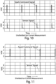
- FIGS. 10 and 11 show data recorded during experiments to test the effect of electromagnetic interference from the sparking event on the ion current signal.
- a time-based ignition command was fed to the ignition system 15 of the spark plug without running the engine.
- a shielded and also an unshielded ion current measurement electrode was used.
- FIG. 10 shows the results using an unshielded ion sensing electrode. A false signal corresponding to spark generation can be clearly seen.
- FIG. 11 shows the voltage measured at the shielded probe, which illustrates the effectiveness of the shield, because little or no voltage caused by unwanted electromagnetic interference is present.
- FIG. 12 illustrates a comparison of signals as they would be present in a running engine with respect to a conventional ionization measurement system and the various embodiments disclosed herein.
- the solid line shows the ion current signal from a shielded, dedicated sensor as discussed and illustrated herein.
- the dotted line illustrates an ionization signal from a conventional spark plug ionization system, where the sparking electrode is also used as an ion current electrode.
- the unwanted current signal is typically present in any circuit arrangement because the same electrode and the same wire is used to carry the sensed current to the detection circuitry. As can be further seen in FIG.
- the signal from the conventional ionization system has significant voltage present that is not due to only ionization within the cylinder, but also due to electromagnetic interference that may need to be accounted for in order to utilize the desired ion current signal.
- the actual ionization current signal is masked by electromagnetic interference present from the sparking voltage.
- FIG. 12 it may be difficult or impossible to determine exactly when combustion (as indicated by ionization current) begins, due to voltage present from other sources in the detection circuit.
Landscapes
- Chemical & Material Sciences (AREA)
- Engineering & Computer Science (AREA)
- Combustion & Propulsion (AREA)
- Mechanical Engineering (AREA)
- General Engineering & Computer Science (AREA)
- Chemical Kinetics & Catalysis (AREA)
- Electrochemistry (AREA)
- Physics & Mathematics (AREA)
- Health & Medical Sciences (AREA)
- Life Sciences & Earth Sciences (AREA)
- Analytical Chemistry (AREA)
- Biochemistry (AREA)
- General Health & Medical Sciences (AREA)
- General Physics & Mathematics (AREA)
- Immunology (AREA)
- Pathology (AREA)
- Ignition Installations For Internal Combustion Engines (AREA)
- Spark Plugs (AREA)
Description
- Exemplary embodiments in general relate to a spark plug combustion ionization sensor for in-cylinder combustion sensing in internal combustion engines.
- Any discussion of the related art throughout the specification should in no way be considered as an admission that such related art is widely known or forms part of common general knowledge in the field.
US 5734094 A discloses an example of a known ion current detector device for use in an internal combustion engine.DE 3828518A1 discloses a spark plug with integrated ion current sensor.EP0926338 A1 discloses a device for measuring the ionization current in a combustion chamber.DE4143480 C2 discloses a spark plug with an ionization current detector electrode. Currently, spark plug-based ionization sensors use the sparking electrode of standard spark plugs to detect ionization in combustion chambers. This is typically done by circuits that are connected to the spark plugs to isolate and measure the ion current that flows during combustion. - Conventional sensors that use unmodified spark plugs typically result in masking or imperfect ion current signals generated during combustion. This occurs because of interference from the high voltage generated by the ignition coils that is applied to the sparking electrode to initiate combustion. In addition, conventional sensors use a circuit connected to the spark plug wire that operates simultaneously with the ignition system.
- Described herein is a spark plug combustion ionization sensor. The spark plug combustion ionization sensor includes one or more dedicated ion current sensing electrodes. The dedicated electrode or electrodes can also be shielded and grounded to substantially reduce or eliminate interference from the high voltage applied to the sparking electrode of a spark plug to initiate the combustion process. Like the sparking electrode, the dedicated sensing electrode may typically extend from the upper portion of the spark plug, through the insulating body or a housing, such as a threaded metal housing, and into the combustion chamber. A sensing circuit can then be connected to the sensing electrode to monitor ion current in an engine's cylinder during combustion.
- The present invention provides a spark plug, comprising: a sparking electrode; an electrically insulating body having a first end and a second end, wherein the electrically insulating body surrounds at least a portion of the sparking electrode, and wherein the sparking electrode exposed at the first end of the electrically insulating body; a housing surrounding a portion of the electrically insulating body, wherein the housing is adapted for mounting the spark plug in an engine cylinder head; a ground electrode connected to the housing, wherein the ground electrode is positioned to create a spark gap between the sparking electrode and the ground electrode; a sensing electrode extending through either the housing or the electrically insulating body, wherein the sensing electrode is electrically isolated from the sparking electrode, wherein a portion of the sensing electrode is exposed near the ground electrode; an insulating material substantially surrounding the sparking electrode along its length; and an electrically conductive shield substantially surrounding the insulating material along its length, the electrically-conductive shield being electrically isolated from the sensing electrode and the sparking electrode, wherein the electrically-conductive shield substantially reduces electromagnetic interference in the sensing electrode.
- In a claimed embodiment, the sensing electrode is electrically isolated from the ground electrode.
- In another claimed embodiment, the electrically conductive shield is configured to be conductively coupled to ground.
- In another claimed embodiment, the housing comprises a metal and wherein the electrically conductive shield is conductively coupled to the metal.
- In another claimed embodiment, the spark plug further comprises at least a second sensing electrode, wherein the second sensing electrode is electrically isolated from the sparking electrode and wherein a portion of the second sensing electrode is exposed at the first end of the electrically insulating body.
- In another claimed embodiment, the sensing electrode is substantially tubular and substantially surrounds the sparking electrode along its length, further comprising: an insulating material disposed between the sparking electrode and the sensing electrode (6) along the length of the sparking electrode.
- In yet another claimed embodiment, the housing comprises a metal and wherein the sensing electrode extends through the housing, further comprising insulating material substantially surrounding the sensing electrode along at least part of its length.
- In another claimed embodiment, the spark plug further comprises at least a second sensing electrode, the second sensing electrode extending through the metal and comprising a conductive element exposed at the first end of the spark plug, further comprising insulating material substantially surrounding the second sensing electrode along its length.
- In another claimed embodiment, the sensing electrode comprises a single conductive element.
- In another claimed embodiment, the sensing electrode comprises a plurality of conductive elements, preferably wherein the plurality of conductive elements include a conductive rod and a resistor.
- In another claimed embodiment, the sensing electrode comprises a conductive land on the electrically insulating body. In this embodiment, the sensing electrode may comprise a plurality of sensing electrodes configured as conductive lands, preferably wherein the spark plug further comprises conductive leads coupled to the conductive lands and extending through the electrically insulating body. Alternatively, the sensing electrode may be electrically isolated from the ground electrode. Alternatively, the housing may be threaded and comprise a metal.
- In another claimed embodiment, the spark plug further comprises an insulating layer substantially surrounding the electrically conductive shield along its length, wherein the sensing electrode is substantially tubular and is disposed between the insulating layer and the electrically insulating body.
- There has thus been outlined, rather broadly, some of the embodiments of the spark plug combustion ionization sensor in order that the detailed description thereof may be better understood, and in order that the present contribution to the art may be better appreciated. There are additional embodiments of the spark plug combustion ionization sensor that will be described hereinafter some of which form the subject matter of the claims appended hereto. The scope of the claimed invention is set out in the appended claims.
- Hereon in, "embodiment" can relate to an embodiment of the claimed invention (as per the appended claims) or to an embodiment that does not form part of the claimed invention but can represent background art useful for understanding the claimed invention.
- Exemplary embodiments will become more fully understood from the detailed description given herein below and the accompanying drawings, wherein like elements are represented by like reference characters, which are given by way of illustration only and thus are not limitative of the example embodiments herein.
-
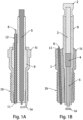
FIG. 1A is a cross section view of a spark plug combustion ionization sensor showing a dedicated ion sensing electrode. -
FIG. 1B is a cross section view of a spark plug combustion ionization sensor showing a dedicated ion sensing electrode. -
FIG. 2A is a front view of a spark plug combustion ionization sensor with a dedicated ion sensing electrode. -
FIG. 2B is a cross section view of the spark plug combustion ionization sensor with a dedicated ion sensing electrode shown inFIG. 2A . -
FIG. 2C is a top view of the spark plug combustion ionization sensor ofFIGS. 2A and 2B . -
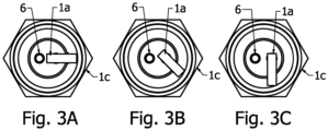
FIG. 3A is a bottom view of a spark plug combustion ionization sensor showing one possible orientation of the ground electrode. -
FIG. 3B is a bottom view of a spark plug combustion ionization sensor showing an alternative orientation of the ground electrode. -
FIG. 3C is a bottom view of a spark plug combustion ionization sensor showing another alternative orientation of the ground electrode. -
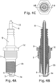
FIG. 4A is a front view of a spark plug combustion ionization sensor with a dedicated sensing electrode configured as a tube in a coaxial configuration. -
FIG. 4B is a cross section view of a spark plug combustion ionization sensor with a dedicated sensing electrode configured as a tube in a coaxial configuration. -
FIG. 4C is a top view of the spark plug combustion ionization sensor ofFIG. 4A . -
FIG. 5A is a front view of a spark plug combustion ionization sensor having multiple ion current sensing electrodes. -
FIG. 5B is a detail perspective view of one end of a spark plug combustion ionization sensor. -
FIG. 5C shows a spark plug combustion ionization sensor having multiple ion current sensing electrodes. -
FIG. 5D shows another spark plug combustion ionization sensor having multiple ion current sensing electrodes. -
FIG. 6A is a front view of a spark plug combustion ionization sensor having multiple sparking electrodes. -
FIG. 6B is a detail perspective view of the spark plug combustion ionization sensor ofFIG. 6A . -
FIG. 7A is a front view of a spark plug combustion ionization sensor having multiple ion current sensing electrodes configured as lands. -
FIG. 7B is a detail perspective view of the spark plug combustion ionization sensor ofFIG. 7A . -
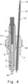
FIG. 8 is a cross sectional view of a spark plug combustion ionization sensor with an unconventional outer housing. -
FIG. 9 is a schematic diagram of an interconnection of an exemplary spark plug combustion ionization sensor and associated circuitry/systems. -
FIG. 10 illustrates experimental data showing the effect of electromagnetic interference on an exemplary unshielded ion current sensing electrode. -
FIG. 11 illustrates experimental data showing the effect of electromagnetic interference on an exemplary shielded ion current sensing electrode. -
FIG. 12 illustrates a comparison of signals obtained from a shielded, dedicated ion current signal electrode and a conventional spark plug ionization system. -
FIG. 13 is a cross section view of a spark plug combustion ionization sensor with a coaxial sensing electrode and shield. -
FIG. 14 is a cross section view of a spark plug combustion ionization sensor with a dedicated sensing electrode and a shielded sparking electrode. - A spark plug according to the present invention is shown in
Fig. 13 or Fig. 14 . - An exemplary spark plug combustion ionization sensor generally comprises a housing, a threaded section that can be screwed into a tapped hole in a cylinder head of an internal combustion engine, a sparking electrode and a ground electrode. In addition, an exemplary sensor may have a dedicated ion current sensing electrode that is electrically isolated from (a) ground and (b) the sparking electrode. As shown in the figures, the sensing electrode may be positioned so that there will not be a spark generated between the two-in other words, so that the spark or sparks will only be generated between the sparking electrode and the ground electrode. This can be accomplished by the distance between the sensing electrode and the sparking electrode, or by different orientations of the electrodes, due to turbulence of the air-fuel mixture in the combustion chamber.
- With reference to the Figures,
FIGS. 1 and2 show an outer shell (or housing) 1 that includes a threadedsection 1b machined onto the outer housing for insertion into the tapped hole, as discussed above. The spark plug can be tightened to the proper torque with a standard size socket wrench engaged withhexagonal feature 1c of the outer housing. When the spark plug is installed, itshousing 1 is seated against the engine's cylinder head by a tapered area or a compression washer (not shown). As with a conventional spark plug, seating the spark plug in the tapped hole creates a ground path for the ground electrode, which is in conductive contact with the threads and the spark plug seat. - The
outer housing 1 surrounds insulatingbody 9, which is made of electrically insulating material, which can be, for example, ceramic (i.e., sintered alumina, alumina silicate, silicon nitride, or mixtures of ceramics). A thinmetal sealing washer 7 and an elastic O-ring 8 may be positioned between the contact areas of theouter housing 1 and the insulatingbody 9 to seal in the combustion gases and maintain pressure inside the combustion chamber, as shown inFIG. 2B .Body 9 typically has high dielectric strength combined with good thermal conductivity. Thebody 9 can accommodate either a single-piece sparking electrode 5 (seeFIG. 1A ) or a multipiece unit (e.g.,FIGS. 1B and2B ) that incorporates a radiofrequency noisesuppressing resistor 4 and also includes ametal connection terminal 2, aconductive rod 3, and a conductive, corrosion-resistant sparkingelectrode 5. Terminal 2 provides for a connection to ignition system 14 (FIG. 9 ) to the sparkingelectrode 5 through a standard snap-fit connector or a threaded connector. - As also shown, the sensor spark plug also includes a i-shaped
ground electrode 1a positioned to create a spark gap with the sparking electrode so that an ignition spark will be generated between the sparkingelectrode 5 and theground electrode 1a to start the combustion process.FIGS. 3A-3C show different possible orientations ofground electrode 1a that are possible, and that may be used based on the in-cylinder turbulence generated by the tumble/swirl flow of the fuel-air mixture passing through the intake port of the engine. - In addition to the components mentioned above,
FIGS. 1 and2 also show a dedicated, electrically-insulatedsensing electrode 6 that extends into the combustion chamber. Ioncurrent sensing electrode 6 is electrically isolated from sparkingelectrode 5 andground electrode 1a.Sensing electrode 6 can be made out of an electrically conductive material that extends on one end into the combustion chamber of an internal combustion engine, and can be connected at the other end to asignal processing unit 13 as shown inFIG. 9 .Sensing electrode 6 can be a onepiece solid rod, or alternatively, it can be comprised of or connected to multiple elements such as a conductive rod, resistors, capacitors, or any set of components capable of carrying ion current through the body of the spark plug. In addition to the configuration shown inFIG. 1 ; thesensing electrode 6 can also be configured as a tube, as shown inFIGS. 4A-4C . In this configuration,sensing electrode 6 can be arranged coaxially to surround sparkingelectrode 5, with an insulatingtube 11 serving to electrically isolate the two elements. - Referring again to
FIG. 1A , thededicated sensing electrode 6 is surrounded by an insulatingtube 11 or other insulating material, which in turn is surrounded byelectromagnetic interference shield 12, which can be conductively coupled to ground. Onepossible way shield 12 can be coupled to ground is by laser welding to theouter housing 1. Such a weld could, for example, be used inFIG. 8 where theshield 12 exits the top ofouter housing 1. In other configurations, such as that ofFIG. 1A , where the shield is not necessarily adjacent to the outer housing, the shield can be grounded through an electrical connector, such as the electrical connector used to connect to the top end ofsensing electrode 6. Shielding thesensing electrode 6 has the advantage of minimizing the electromagnetic noise imposed on the ion current signal during sparking, or from any other possible source. -
FIG. 1B shows an alternate arrangement, wheresensing electrode 6 is still positioned within an insulatingtube 11 or is insulating using other insulating material, but the resulting assembly is contained within theouter metal housing 1 of the spark plug, which as discussed above, is grounded. In this arrangement, a separate shield surrounding the sensing electrode is not required, since the grounded housing acts as a shield, Either configuration (e.g., 1A or 1B) can substantially reduce or eliminate electromagnetic interference in the sensed ion current signal, which allows for more accurate and simplified measurement of combustion within the cylinder. Further, as shown inFIG. 1A , thesensing electrode 6 can be substantially parallel to the sparkingelectrode 5, or as shown inFIG. 1B , it can be at an angle to the sparking electrode if necessary to accommodate connectors or for better clearance with other parts of the spark plug. - Any number of known techniques can be used to make an electrical connection from the top of sensing
electrode 6 to signal processing circuitry. For example, the top ofelectrode 6 can be configured to mate with a conventional automotive-type connector in order to allow wiring to a signal processing unit, such assignal processing unit 13 shown inFIG. 9 . - Other electrode configurations are possible. For example, as shown in
FIG. 7B ,multiple sensing electrodes 6 are arranged in a land-type configuration. In this configuration, the sensing electrodes comprise conductive lands on the spark plug's insulating body with electrically conductive leads or other elements passing through or onbody 9 to the top end of the spark plug, where they can be connected as described herein to sensing circuitry. The conductive lands that comprisesensing electrodes 6 may also be printed using an electrically conductive material or alloy on the outer surface ofbody 9. - As also shown in
FIGS. 5B-D ,multiple sensing electrodes 6, rather than the single element shown inFIGS. 1 and2 , can also be used. In this arrangement,electrodes 6 pass through multiple holes inbody 9. These holes and electrodes can be also used for multiple purposes, such as fuel injector nozzles or multiple sparking electrodes (as shown inFIG. 6B ). Further, in a configuration with multiple sparking electrodes, some or all of the sparking electrodes can also be used for ion current measurement. One such configuration is shown inFIG. 6B . In this configuration, one or more of the sparking electrodes can be used as dedicated ion sensing probes, so that the electrodes are no longer used for sparking, but as discussed above, can be used in conjunction with a signal processing unit such assignal processing unit 13 inFIG. 9 , to measure ion current. - In some cases, it may be advantageous to modify the spark plug bore of the cylinder head in order to allow for an unconventional spark plug, as shown in
FIG. 8 . This would allow for installation of an ion sensor assembly with different shapes and designs, to ensure the integrity of the ion current signal without the space constraints of conventional spark plug shapes and sizes. The spark plug shown inFIG. 8 can still include all the basic elements discussed above regardingFIG. 1B . - As shown in
FIG. 13 , additional tubular elements can be added to an arrangement similar toFIG. 4 . In this claimed arrangement, the sparkingelectrode 5 is surrounded byinsulator 11a, which in turn is surrounded byshield 12, which can be grounded. Another insulatinglayer 11b surroundsshield 12, which is further surrounded by sensingelectrode 6, configured here as a tube as inFIGS. 4A-4C . In this claimed embodiment, rather than surrounding an individual sensing electrode,shield 12 operates as a shield around the sparking electrode, so that even if multiple sensing electrodes are used, they will be shielded from electromagnetic noise. - In the claimed embodiment of
FIG. 14 , the sparking electrode is also surrounded by aninsulator 11 andshield 12. In this claimed embodiment, adedicated sensing electrode 6 can pass through the insulating body without the need for a shield immediately surroundingelectrode 6, since the sparking electrode is shielded. - Referring to
FIG. 9 , in a typical spark-ignited internal combustion engine, anengine control unit 14 sends a spark timing command to theignition system 15 of the desired engine cylinder to fire based on the firing order of the engine. Electric current flows to the sparkingelectrode 5 passing through the conductingrod 3 and the radio frequency noise cancelling resistor 4 (FIG. 1 ) generating high voltage across the spark gap. A spark is then generated between the sparkingelectrode 5 and theground electrode 1a when the voltage across the spark gap exceeds the dielectric strength of the air-fuel mixture within the spark gap, to initiate a flame kernel followed by the combustion process including flame propagation across the combustion chamber. - The energy released by the sparking and flame propagation ionizes the fuel-air mixture in the combustion chamber, producing ions and free electrons during the combustion process. To measure this combustion ionization, a DC or AC voltage can be supplied to the
sensing electrode 6 to attract ions and electrons and complete the circuit between the insulated electrode and the engine block and/or in-cylinder multiengine components. Electrons and negative ions are attracted to the positively charged electrode tip while positive ions are attracted to the ground electrode or any ground path present in the cylinder. This movement of electrons and ions results in closing the ionization circuit, allowing ion current to flow through a resistor with a known value in thesignal processing unit 13. Ion current can be calculated inunit 13 by dividing the measured voltage across the resistor by the resistor value, or by other known means. - The ion current measured in this manner has a minimum of interference from the voltage generated to cause the ignition spark. For example, the ion current path is not the same path caused by the sparking
electrode 5, and may flow from the sensing electrode to ground in a different location than the ground electrode of the spark plug. For this reason and due to the shielding of the dedicated sensing electrode, the ionization current produced by the dedicated electrode provides a more accurate representation of combustion events within the cylinder, relatively unaffected by the sparking electrode. - An ion signal can be detected from the very first generation of free ions and electrons inside the combustion chamber through the sensing electrode without the interference of the electromagnetic noise generated by the ignition process. In cases of multi-sparking events where multiple sparks take place within the same engine cycle, the ion current signal can still be captured from start to finish with little or no interference from the ignition event.
- Since the ion current signal is produced by ionizing the air-fuel mixture species depending on in-cylinder temperature, pressure, equivalence ratio and other operating parameters, it is possible to quantify the ionized species and obtain combustion and emission parameters using the measured ion current signal.
- An in-cylinder combustion ionization signal obtained from the sensor can be used as a feedback signal to provide cycle-by-cycle and cylinder-by-cylinder control over the combustion process in internal combustion engines. Such control can be used to help engines meet stringent emission standards and also to achieve improved fuel economy. In addition, advanced combustion techniques such as lean homogeneous operation or lean stratified operation can be used successfully on engines using combustion feedback derived from the ion current signal. Combustion abnormalities such as engine knocking, misfires or late firing can also be detected with such a signal.
- The claimed embodiments herein enable in-cylinder sensing such as the measurement of ion current signal through a dedicated electrically insulated probe introduced to the combustion chamber, without any interference from the ignition event caused by the high voltage generated by the ignition coils and applied to the sparking electrode to initiate combustion. Sparking operation can occur simultaneously with in-cylinder ion current sensing with minimum or no distortion to the shape of the ion current signal. The exemplary, dedicated ion current sensor also has the advantage of eliminating the need to use additional circuitry to separate or isolate the ion current signal from the spark generating voltage.
- As discussed, since a single-purpose, isolated circuit can be used to measure ion current, the monitoring circuitry in
signal processing unit 13 can be in operation continuously. For example, an AC or DC bias signal can be applied to one or more dedicated ion current sensing probes continuously, even when the spark command is present. Thus, as soon as conditions in the cylinder permit ion current flow, it can be measured by the sensing electrode and its associated circuitry insignal processing unit 13. - Experiments have shown that it is advantageous to shield the electrically insulated ion current probe against electromagnetic interference from spark generation. Such shielding can be achieved by, for example, installing a metal tube around the electrically insulated sensing electrode, the metal tube also being conductively coupled to ground through the outer threaded housing.
FIGS. 10 and 11 show data recorded during experiments to test the effect of electromagnetic interference from the sparking event on the ion current signal. In the experiment, a time-based ignition command was fed to theignition system 15 of the spark plug without running the engine. A shielded and also an unshielded ion current measurement electrode was used.FIG. 10 shows the results using an unshielded ion sensing electrode. A false signal corresponding to spark generation can be clearly seen. Had the engine been running, this undesired signal would be imposed on the ion current signal, making it more difficult to accurately measure the ion current.FIG. 11 shows the voltage measured at the shielded probe, which illustrates the effectiveness of the shield, because little or no voltage caused by unwanted electromagnetic interference is present. -
FIG. 12 illustrates a comparison of signals as they would be present in a running engine with respect to a conventional ionization measurement system and the various embodiments disclosed herein. The solid line shows the ion current signal from a shielded, dedicated sensor as discussed and illustrated herein. The dotted line illustrates an ionization signal from a conventional spark plug ionization system, where the sparking electrode is also used as an ion current electrode. The unwanted current signal is typically present in any circuit arrangement because the same electrode and the same wire is used to carry the sensed current to the detection circuitry. As can be further seen inFIG. 12 , the signal from the conventional ionization system has significant voltage present that is not due to only ionization within the cylinder, but also due to electromagnetic interference that may need to be accounted for in order to utilize the desired ion current signal. When using the signal from a conventional ionization system, the actual ionization current signal is masked by electromagnetic interference present from the sparking voltage. As can be seen inFIG. 12 , it may be difficult or impossible to determine exactly when combustion (as indicated by ionization current) begins, due to voltage present from other sources in the detection circuit. - Unless otherwise defined, all technical and scientific terms used herein have the same meaning as commonly understood by one of ordinary skill in the art to which this invention belongs. Although methods and materials similar to or equivalent to those described herein can be used in the practice or testing of the spark plug combustion ionization sensor, suitable methods and materials are described above.
Claims (15)
- A spark plug, comprising: a
sparking electrode (5);an electrically insulating body (9) having a first end and a second end, wherein the electrically insulating body (9) surrounds at least a portion of the sparking electrode (5), and wherein the sparking electrode (5) exposed at the first end of the electrically insulating body (9);a housing (1) surrounding a portion of the electrically insulating body (9), wherein the housing (1) is adapted for mounting the spark plug in an engine cylinder head;a ground electrode (1a) connected to the housing (1), wherein the ground electrode (1a) is positioned to create a spark gap between the sparking electrode (5) and the ground electrode (1a);a sensing electrode (6) extending through either the housing (1) or the electrically insulating body (9), wherein the sensing electrode (6) is electrically isolated from the sparking electrode (5), wherein a portion of the sensing electrode (6) is exposed near the ground electrode (1a);characterized in that, the spark plug further comprises:an insulating material substantially surrounding the sparking electrode (5) along its length; andan electrically conductive shield (12) substantially surrounding the insulating material along its length, the electrically-conductive shield (12) being electrically isolated from the sensing electrode (6) and the sparking electrode (5), wherein the electrically-conductive shield (12) substantially reduces electromagnetic interference in the sensing electrode (6). - The spark plug of claim 1, wherein the sensing electrode (6) is electrically isolated from the ground electrode (1a).
- The spark plug of claim 1, wherein the electrically conductive shield (12) is configured to be conductively coupled to ground.
- The spark plug of claim 1, wherein the housing (1) comprises a metal and wherein the electrically conductive shield (12) is conductively coupled to the metal.
- The spark plug of claim 1, further comprising at least a second sensing electrode, wherein the second sensing electrode is electrically isolated from the sparking electrode (5) and wherein a portion of the second sensing electrode is exposed at the first end of the electrically insulating body (9).
- The spark plug of claim 1, wherein the sensing electrode (6) is substantially tubular and substantially surrounds the sparking electrode (5) along its length, further comprising:
an insulating material disposed between the sparking electrode (5) and the sensing electrode (6) along the length of the sparking electrode (5). - The spark plug of claim 1, wherein the housing (1) comprises a metal and wherein the sensing electrode (6) extends through the housing (1), further comprising:
insulating material (11) substantially surrounding the sensing electrode (6) along at least part of its length. - The spark plug of claim 1, further comprising at least a second sensing electrode, the second sensing electrode extending through the metal and comprising a conductive element exposed at the first end of the spark plug, further comprising:
insulating material substantially surrounding the second sensing electrode along its length. - The spark plug of claim 1, wherein the sensing electrode (6) comprises a single conductive element.
- The spark plug of claim 1, wherein the sensing electrode (6) comprises a plurality of conductive elements, preferably wherein the plurality of conductive elements include a conductive rod and a resistor.
- The spark plug of claim 1, wherein the sensing electrode (6) comprises a conductive land on the electrically insulating body (9).
- The spark plug of claim 11, wherein the sensing electrode (6) comprises a plurality of sensing electrodes configured as conductive lands, preferably wherein the spark plug further comprises conductive leads coupled to the conductive lands and extending through the electrically insulating body (9).
- The spark plug of claim 11, wherein the at least one sensing electrode (6) is electrically isolated from the ground electrode (1a).
- The spark plug of claim 11, wherein the housing (1) is threaded (1b) and comprises a metal.
- The spark plug of claim 1 wherein the spark plug further comprises an insulating layer (11b) substantially surrounding the electrically conductive shield (12) along its length, wherein the sensing electrode (6) is substantially tubular and is disposed between the insulating layer (11b) and the electrically insulating body (9).
Applications Claiming Priority (2)
| Application Number | Priority Date | Filing Date | Title |
|---|---|---|---|
| US201662425127P | 2016-11-22 | 2016-11-22 | |
| PCT/US2017/063015 WO2018098278A1 (en) | 2016-11-22 | 2017-11-22 | Spark plug combustion ionization sensor |
Publications (3)
| Publication Number | Publication Date |
|---|---|
| EP3545187A1 EP3545187A1 (en) | 2019-10-02 |
| EP3545187A4 EP3545187A4 (en) | 2020-07-22 |
| EP3545187B1 true EP3545187B1 (en) | 2025-03-05 |
Family
ID=62144869
Family Applications (1)
| Application Number | Title | Priority Date | Filing Date |
|---|---|---|---|
| EP17873286.3A Active EP3545187B1 (en) | 2016-11-22 | 2017-11-22 | Spark plug combustion ionization sensor |
Country Status (5)
| Country | Link |
|---|---|
| US (2) | US20180142664A1 (en) |
| EP (1) | EP3545187B1 (en) |
| JP (1) | JP6999186B2 (en) |
| CN (1) | CN110226033A (en) |
| WO (1) | WO2018098278A1 (en) |
Families Citing this family (10)
| Publication number | Priority date | Publication date | Assignee | Title |
|---|---|---|---|---|
| EP3900129B1 (en) * | 2018-12-20 | 2025-04-30 | AI Alpine US Bidco Inc. | System and method for spark plug identification and engine monitoring |
| KR102842806B1 (en) * | 2020-06-17 | 2025-08-05 | 현대자동차 주식회사 | Dual sprrk plug |
| US11545816B2 (en) | 2020-11-04 | 2023-01-03 | Federal-Mogul Ignition Gmbh | Spark plug with multiple spark gaps |
| KR102869048B1 (en) * | 2020-12-11 | 2025-10-10 | 현대자동차 주식회사 | Dual sprrk plug |
| KR20230027482A (en) * | 2021-08-19 | 2023-02-28 | 현대자동차주식회사 | Spark plug |
| US11621544B1 (en) | 2022-01-14 | 2023-04-04 | Federal-Mogul Ignition Gmbh | Spark plug electrode and method of manufacturing the same |
| US11831130B2 (en) | 2022-03-29 | 2023-11-28 | Federal-Mogul Ignition Gmbh | Spark plug, spark plug electrode, and method of manufacturing the same |
| CN114856879B (en) * | 2022-04-11 | 2023-04-07 | 哈尔滨工程大学 | Diesel engine nozzle device capable of being used for combustion state online monitoring and detection method |
| US11837852B1 (en) | 2022-07-27 | 2023-12-05 | Federal-Mogul Ignition Gmbh | Spark plug electrode with electrode tip directly thermally coupled to heat dissipating core and method of manufacturing the same |
| US12191637B1 (en) | 2024-06-14 | 2025-01-07 | Federal-Mogul Ignition Gmbh | Spark plug with cooling features and method of manufacturing the same |
Citations (1)
| Publication number | Priority date | Publication date | Assignee | Title |
|---|---|---|---|---|
| EP0926338B1 (en) * | 1997-12-19 | 2003-08-13 | Renault s.a.s. | Device for measuring the ionisation current in a combustion chamber |
Family Cites Families (33)
| Publication number | Priority date | Publication date | Assignee | Title |
|---|---|---|---|---|
| US2571507A (en) * | 1950-06-06 | 1951-10-16 | Gen Motors Corp | Pressure indicator |
| US3235763A (en) * | 1960-09-15 | 1966-02-15 | Gen Motors Corp | Igniter plug with spark-sensing probe |
| US3394285A (en) * | 1966-05-20 | 1968-07-23 | Donald E. Lindsay | Two-gap spark plug with series resistor for each gap |
| US4361036A (en) * | 1981-01-08 | 1982-11-30 | Levenson Sol J | Engine analyzer |
| JPS57193777A (en) * | 1981-05-22 | 1982-11-29 | Nissan Motor Co Ltd | Spark ignition type internal combustion device |
| DE3203200A1 (en) * | 1982-01-30 | 1983-08-04 | Bosch Gmbh Robert | Spark plug with oxygen sensor |
| DE3828518A1 (en) * | 1988-08-23 | 1990-03-01 | Pierburg Gmbh | Spark plug with integrated ion current sensor |
| KR950004615B1 (en) * | 1990-09-27 | 1995-05-03 | 미쓰비시덴키 가부시키가이샤 | Spark Plugs for Internal Combustion Engines |
| JPH04134182A (en) * | 1990-09-27 | 1992-05-08 | Mitsubishi Electric Corp | Spark plug for internal combustion engine |
| DE4143480C2 (en) * | 1990-09-27 | 1996-06-13 | Mitsubishi Electric Corp | Spark plug with an ionization current detector electrode |
| US5376886A (en) * | 1992-02-06 | 1994-12-27 | Honda Giken Kogyo Kabushiki Kaisha | Ignition distributor cap with misfire detecting capacitor for internal combustion engine |
| US5734094A (en) * | 1993-05-31 | 1998-03-31 | Ngk Spark Plug Co., Ltd. | Ion current detector device for use in an internal combustion engine |
| JPH06338377A (en) * | 1993-05-31 | 1994-12-06 | Ngk Spark Plug Co Ltd | Ion current detection device for internal combustion engine |
| DE4331269C2 (en) | 1993-09-15 | 1995-07-13 | Bosch Gmbh Robert | Process for producing a spark plug with a spark gap and spark plugs produced by the process |
| JPH08128380A (en) * | 1994-11-01 | 1996-05-21 | Ngk Spark Plug Co Ltd | Secondary voltage detector for gasoline engine and manufacturing method thereof |
| US6094990A (en) * | 1998-06-30 | 2000-08-01 | Cooper Automotive Products, Inc. | Spark plug with concentric pressure sensor |
| JP2000068031A (en) * | 1998-08-18 | 2000-03-03 | Ngk Spark Plug Co Ltd | Spark plug and ignition system having ion current detection function using the spark plug |
| DE10047498A1 (en) | 2000-09-26 | 2002-04-18 | Bosch Gmbh Robert | Compact-type sparking plug for motor vehicles, has insulator element joined to housing by friction-locked joint aligned in radial direction |
| JP2002124362A (en) * | 2000-10-19 | 2002-04-26 | Ngk Spark Plug Co Ltd | Spark plug with built-in pressure sensor |
| US7098581B2 (en) * | 2003-09-15 | 2006-08-29 | Cleeves James M | Spark plug |
| US6994073B2 (en) * | 2003-10-31 | 2006-02-07 | Woodward Governor Company | Method and apparatus for detecting ionization signal in diesel and dual mode engines with plasma discharge system |
| US7093421B2 (en) * | 2004-02-10 | 2006-08-22 | General Electric Company | Spark igniter for gas turbine engine |
| US8922102B2 (en) * | 2006-05-12 | 2014-12-30 | Enerpulse, Inc. | Composite spark plug |
| DE102006033480A1 (en) * | 2006-07-19 | 2008-01-24 | Robert Bosch Gmbh | Spark plug, especially for high combustion chamber pressures |
| JP5525454B2 (en) * | 2008-01-28 | 2014-06-18 | フラム・グループ・アイピー・エルエルシー | High position thread ground shield |
| JP5476123B2 (en) | 2008-04-09 | 2014-04-23 | 日本特殊陶業株式会社 | Spark plug for internal combustion engine |
| WO2010000709A1 (en) * | 2008-07-02 | 2010-01-07 | Agc Flat Glass Europe Sa | Power supply for hot oxygen burner |
| CH699078A1 (en) * | 2008-07-02 | 2010-01-15 | Kistler Holding Ag | Spark plug in basic structure with pressure sensor. |
| JP4619443B2 (en) | 2009-03-31 | 2011-01-26 | 日本特殊陶業株式会社 | Spark plug |
| US8244447B2 (en) | 2010-01-27 | 2012-08-14 | Robert Bosch Gmbh | Spark plug having a thermosensor |
| JP5393830B2 (en) | 2012-03-28 | 2014-01-22 | 日本特殊陶業株式会社 | Spark plug |
| CA2818547C (en) | 2012-09-18 | 2014-08-12 | Ming Zheng | Multi-coil spark ignition system |
| JP5896890B2 (en) * | 2012-12-10 | 2016-03-30 | 株式会社デンソー | Spark plug for internal combustion engine |
-
2017
- 2017-11-22 CN CN201780084048.7A patent/CN110226033A/en active Pending
- 2017-11-22 WO PCT/US2017/063015 patent/WO2018098278A1/en not_active Ceased
- 2017-11-22 JP JP2019528453A patent/JP6999186B2/en active Active
- 2017-11-22 EP EP17873286.3A patent/EP3545187B1/en active Active
- 2017-11-22 US US15/820,870 patent/US20180142664A1/en not_active Abandoned
-
2020
- 2020-04-29 US US16/861,578 patent/US10975829B2/en active Active
Patent Citations (1)
| Publication number | Priority date | Publication date | Assignee | Title |
|---|---|---|---|---|
| EP0926338B1 (en) * | 1997-12-19 | 2003-08-13 | Renault s.a.s. | Device for measuring the ionisation current in a combustion chamber |
Also Published As
| Publication number | Publication date |
|---|---|
| CN110226033A (en) | 2019-09-10 |
| US20200256308A1 (en) | 2020-08-13 |
| EP3545187A1 (en) | 2019-10-02 |
| JP2020506497A (en) | 2020-02-27 |
| EP3545187A4 (en) | 2020-07-22 |
| US10975829B2 (en) | 2021-04-13 |
| JP6999186B2 (en) | 2022-01-18 |
| US20180142664A1 (en) | 2018-05-24 |
| WO2018098278A1 (en) | 2018-05-31 |
Similar Documents
| Publication | Publication Date | Title |
|---|---|---|
| US10975829B2 (en) | Spark plug combustion ionization sensor | |
| KR950003272B1 (en) | Spark plug current detection device of internal combustion engine | |
| JPS6238652B2 (en) | ||
| EP2171813B1 (en) | Ignition device for internal combustion engine | |
| US20070261471A1 (en) | Soot sensor | |
| CN113054535B (en) | Spark plug for high frequency ignition system | |
| JP3900053B2 (en) | Ignition device for internal combustion engine | |
| EP1036268B1 (en) | Method for measuring the proportion of particles in the exhaust gases from an internal combustion engine | |
| US6505500B1 (en) | Arrangement for detecting ionization in the combustion chamber of a diesel motor, including associated measurement and calibration devices | |
| JPS61272626A (en) | Device for detecting variation of pressure in combustion chamber for internal combustion engine | |
| US3343366A (en) | Spark discharge monitoring device | |
| US20070159047A1 (en) | Spark plug having excellent capabilities of detecting ion current and suppressing inside sparks | |
| JPS60184972A (en) | Ignition apparatus for internal combustion engine | |
| JP3864871B2 (en) | Method and apparatus for inspecting internal combustion engine ignition device | |
| JP2017214917A (en) | Control device and knock analysis method for internal combustion engine | |
| US6655367B2 (en) | Plug-hole-installed ignition coil unit for internal combustion engines | |
| CN104221234A (en) | High Power Semi Surface Gap Spark Plugs | |
| JP2000034969A (en) | Combustion state detection device using spark plug | |
| JP2000068031A (en) | Spark plug and ignition system having ion current detection function using the spark plug | |
| US2913659A (en) | Testing device for spark plugs | |
| JP2007303285A (en) | Ion current detector | |
| JP3663806B2 (en) | Combustion equipment | |
| RU2620477C1 (en) | Device for measurement, control and diagnostics of combustion process in combustion engine chamber | |
| WO2021024172A1 (en) | Spark plug and electronic ignition system for an internal engine | |
| JP2022178364A (en) | Spark plug |
Legal Events
| Date | Code | Title | Description |
|---|---|---|---|
| STAA | Information on the status of an ep patent application or granted ep patent |
Free format text: STATUS: THE INTERNATIONAL PUBLICATION HAS BEEN MADE |
|
| PUAI | Public reference made under article 153(3) epc to a published international application that has entered the european phase |
Free format text: ORIGINAL CODE: 0009012 |
|
| STAA | Information on the status of an ep patent application or granted ep patent |
Free format text: STATUS: REQUEST FOR EXAMINATION WAS MADE |
|
| 17P | Request for examination filed |
Effective date: 20190607 |
|
| AK | Designated contracting states |
Kind code of ref document: A1 Designated state(s): AL AT BE BG CH CY CZ DE DK EE ES FI FR GB GR HR HU IE IS IT LI LT LU LV MC MK MT NL NO PL PT RO RS SE SI SK SM TR |
|
| AX | Request for extension of the european patent |
Extension state: BA ME |
|
| DAV | Request for validation of the european patent (deleted) | ||
| DAX | Request for extension of the european patent (deleted) | ||
| A4 | Supplementary search report drawn up and despatched |
Effective date: 20200622 |
|
| RIC1 | Information provided on ipc code assigned before grant |
Ipc: F02P 17/12 20060101ALI20200616BHEP Ipc: H01T 13/06 20060101ALI20200616BHEP Ipc: H01T 13/22 20060101ALI20200616BHEP Ipc: H01T 13/08 20060101ALI20200616BHEP Ipc: F02P 13/00 20060101AFI20200616BHEP Ipc: G01L 23/22 20060101ALI20200616BHEP |
|
| STAA | Information on the status of an ep patent application or granted ep patent |
Free format text: STATUS: EXAMINATION IS IN PROGRESS |
|
| 17Q | First examination report despatched |
Effective date: 20221201 |
|
| GRAP | Despatch of communication of intention to grant a patent |
Free format text: ORIGINAL CODE: EPIDOSNIGR1 |
|
| STAA | Information on the status of an ep patent application or granted ep patent |
Free format text: STATUS: GRANT OF PATENT IS INTENDED |
|
| INTG | Intention to grant announced |
Effective date: 20240927 |
|
| GRAS | Grant fee paid |
Free format text: ORIGINAL CODE: EPIDOSNIGR3 |
|
| GRAA | (expected) grant |
Free format text: ORIGINAL CODE: 0009210 |
|
| STAA | Information on the status of an ep patent application or granted ep patent |
Free format text: STATUS: THE PATENT HAS BEEN GRANTED |
|
| AK | Designated contracting states |
Kind code of ref document: B1 Designated state(s): AL AT BE BG CH CY CZ DE DK EE ES FI FR GB GR HR HU IE IS IT LI LT LU LV MC MK MT NL NO PL PT RO RS SE SI SK SM TR |
|
| REG | Reference to a national code |
Ref country code: GB Ref legal event code: FG4D |
|
| REG | Reference to a national code |
Ref country code: CH Ref legal event code: EP |
|
| REG | Reference to a national code |
Ref country code: DE Ref legal event code: R096 Ref document number: 602017088214 Country of ref document: DE |
|
| REG | Reference to a national code |
Ref country code: IE Ref legal event code: FG4D |
|
| PG25 | Lapsed in a contracting state [announced via postgrant information from national office to epo] |
Ref country code: RS Free format text: LAPSE BECAUSE OF FAILURE TO SUBMIT A TRANSLATION OF THE DESCRIPTION OR TO PAY THE FEE WITHIN THE PRESCRIBED TIME-LIMIT Effective date: 20250605 |
|
| PG25 | Lapsed in a contracting state [announced via postgrant information from national office to epo] |
Ref country code: FI Free format text: LAPSE BECAUSE OF FAILURE TO SUBMIT A TRANSLATION OF THE DESCRIPTION OR TO PAY THE FEE WITHIN THE PRESCRIBED TIME-LIMIT Effective date: 20250305 |
|
| REG | Reference to a national code |
Ref country code: NL Ref legal event code: MP Effective date: 20250305 |
|
| PG25 | Lapsed in a contracting state [announced via postgrant information from national office to epo] |
Ref country code: ES Free format text: LAPSE BECAUSE OF FAILURE TO SUBMIT A TRANSLATION OF THE DESCRIPTION OR TO PAY THE FEE WITHIN THE PRESCRIBED TIME-LIMIT Effective date: 20250305 |
|
| REG | Reference to a national code |
Ref country code: LT Ref legal event code: MG9D |
|
| PG25 | Lapsed in a contracting state [announced via postgrant information from national office to epo] |
Ref country code: NO Free format text: LAPSE BECAUSE OF FAILURE TO SUBMIT A TRANSLATION OF THE DESCRIPTION OR TO PAY THE FEE WITHIN THE PRESCRIBED TIME-LIMIT Effective date: 20250605 |
|
| PG25 | Lapsed in a contracting state [announced via postgrant information from national office to epo] |
Ref country code: HR Free format text: LAPSE BECAUSE OF FAILURE TO SUBMIT A TRANSLATION OF THE DESCRIPTION OR TO PAY THE FEE WITHIN THE PRESCRIBED TIME-LIMIT Effective date: 20250305 |
|
| PG25 | Lapsed in a contracting state [announced via postgrant information from national office to epo] |
Ref country code: LV Free format text: LAPSE BECAUSE OF FAILURE TO SUBMIT A TRANSLATION OF THE DESCRIPTION OR TO PAY THE FEE WITHIN THE PRESCRIBED TIME-LIMIT Effective date: 20250305 |
|
| PG25 | Lapsed in a contracting state [announced via postgrant information from national office to epo] |
Ref country code: BG Free format text: LAPSE BECAUSE OF FAILURE TO SUBMIT A TRANSLATION OF THE DESCRIPTION OR TO PAY THE FEE WITHIN THE PRESCRIBED TIME-LIMIT Effective date: 20250305 Ref country code: GR Free format text: LAPSE BECAUSE OF FAILURE TO SUBMIT A TRANSLATION OF THE DESCRIPTION OR TO PAY THE FEE WITHIN THE PRESCRIBED TIME-LIMIT Effective date: 20250606 |
|
| REG | Reference to a national code |
Ref country code: AT Ref legal event code: MK05 Ref document number: 1773125 Country of ref document: AT Kind code of ref document: T Effective date: 20250305 |
|
| PG25 | Lapsed in a contracting state [announced via postgrant information from national office to epo] |
Ref country code: NL Free format text: LAPSE BECAUSE OF FAILURE TO SUBMIT A TRANSLATION OF THE DESCRIPTION OR TO PAY THE FEE WITHIN THE PRESCRIBED TIME-LIMIT Effective date: 20250305 |
|
| PG25 | Lapsed in a contracting state [announced via postgrant information from national office to epo] |
Ref country code: SE Free format text: LAPSE BECAUSE OF FAILURE TO SUBMIT A TRANSLATION OF THE DESCRIPTION OR TO PAY THE FEE WITHIN THE PRESCRIBED TIME-LIMIT Effective date: 20250305 |
|
| PG25 | Lapsed in a contracting state [announced via postgrant information from national office to epo] |
Ref country code: SM Free format text: LAPSE BECAUSE OF FAILURE TO SUBMIT A TRANSLATION OF THE DESCRIPTION OR TO PAY THE FEE WITHIN THE PRESCRIBED TIME-LIMIT Effective date: 20250305 |
|
| PG25 | Lapsed in a contracting state [announced via postgrant information from national office to epo] |
Ref country code: PT Free format text: LAPSE BECAUSE OF FAILURE TO SUBMIT A TRANSLATION OF THE DESCRIPTION OR TO PAY THE FEE WITHIN THE PRESCRIBED TIME-LIMIT Effective date: 20250707 |
|
| PG25 | Lapsed in a contracting state [announced via postgrant information from national office to epo] |
Ref country code: IT Free format text: LAPSE BECAUSE OF FAILURE TO SUBMIT A TRANSLATION OF THE DESCRIPTION OR TO PAY THE FEE WITHIN THE PRESCRIBED TIME-LIMIT Effective date: 20250305 Ref country code: PL Free format text: LAPSE BECAUSE OF FAILURE TO SUBMIT A TRANSLATION OF THE DESCRIPTION OR TO PAY THE FEE WITHIN THE PRESCRIBED TIME-LIMIT Effective date: 20250305 |
|
| PG25 | Lapsed in a contracting state [announced via postgrant information from national office to epo] |
Ref country code: AT Free format text: LAPSE BECAUSE OF FAILURE TO SUBMIT A TRANSLATION OF THE DESCRIPTION OR TO PAY THE FEE WITHIN THE PRESCRIBED TIME-LIMIT Effective date: 20250305 |
|
| PG25 | Lapsed in a contracting state [announced via postgrant information from national office to epo] |
Ref country code: CZ Free format text: LAPSE BECAUSE OF FAILURE TO SUBMIT A TRANSLATION OF THE DESCRIPTION OR TO PAY THE FEE WITHIN THE PRESCRIBED TIME-LIMIT Effective date: 20250305 Ref country code: EE Free format text: LAPSE BECAUSE OF FAILURE TO SUBMIT A TRANSLATION OF THE DESCRIPTION OR TO PAY THE FEE WITHIN THE PRESCRIBED TIME-LIMIT Effective date: 20250305 |
|
| PG25 | Lapsed in a contracting state [announced via postgrant information from national office to epo] |
Ref country code: RO Free format text: LAPSE BECAUSE OF FAILURE TO SUBMIT A TRANSLATION OF THE DESCRIPTION OR TO PAY THE FEE WITHIN THE PRESCRIBED TIME-LIMIT Effective date: 20250305 |
|
| PG25 | Lapsed in a contracting state [announced via postgrant information from national office to epo] |
Ref country code: SK Free format text: LAPSE BECAUSE OF FAILURE TO SUBMIT A TRANSLATION OF THE DESCRIPTION OR TO PAY THE FEE WITHIN THE PRESCRIBED TIME-LIMIT Effective date: 20250305 |
|
| PG25 | Lapsed in a contracting state [announced via postgrant information from national office to epo] |
Ref country code: IS Free format text: LAPSE BECAUSE OF FAILURE TO SUBMIT A TRANSLATION OF THE DESCRIPTION OR TO PAY THE FEE WITHIN THE PRESCRIBED TIME-LIMIT Effective date: 20250705 |
|
| REG | Reference to a national code |
Ref country code: DE Ref legal event code: R097 Ref document number: 602017088214 Country of ref document: DE |
|
| PGFP | Annual fee paid to national office [announced via postgrant information from national office to epo] |
Ref country code: DE Payment date: 20251127 Year of fee payment: 9 |
|
| PLBE | No opposition filed within time limit |
Free format text: ORIGINAL CODE: 0009261 |
|
| STAA | Information on the status of an ep patent application or granted ep patent |
Free format text: STATUS: NO OPPOSITION FILED WITHIN TIME LIMIT |
|
| PG25 | Lapsed in a contracting state [announced via postgrant information from national office to epo] |
Ref country code: DK Free format text: LAPSE BECAUSE OF FAILURE TO SUBMIT A TRANSLATION OF THE DESCRIPTION OR TO PAY THE FEE WITHIN THE PRESCRIBED TIME-LIMIT Effective date: 20250305 |
|
| REG | Reference to a national code |
Ref country code: CH Ref legal event code: L10 Free format text: ST27 STATUS EVENT CODE: U-0-0-L10-L00 (AS PROVIDED BY THE NATIONAL OFFICE) Effective date: 20260114 |
|
| PGFP | Annual fee paid to national office [announced via postgrant information from national office to epo] |
Ref country code: FR Payment date: 20251127 Year of fee payment: 9 |
|
| 26N | No opposition filed |
Effective date: 20251208 |