EP3545175B1 - Verfahren zur steuerung eines turbomaschinenventils - Google Patents
Verfahren zur steuerung eines turbomaschinenventils Download PDFInfo
- Publication number
- EP3545175B1 EP3545175B1 EP17811651.3A EP17811651A EP3545175B1 EP 3545175 B1 EP3545175 B1 EP 3545175B1 EP 17811651 A EP17811651 A EP 17811651A EP 3545175 B1 EP3545175 B1 EP 3545175B1
- Authority
- EP
- European Patent Office
- Prior art keywords
- engine speed
- filtering
- determining
- valve
- position command
- Prior art date
- Legal status (The legal status is an assumption and is not a legal conclusion. Google has not performed a legal analysis and makes no representation as to the accuracy of the status listed.)
- Active
Links
Images




Classifications
-
- F—MECHANICAL ENGINEERING; LIGHTING; HEATING; WEAPONS; BLASTING
- F01—MACHINES OR ENGINES IN GENERAL; ENGINE PLANTS IN GENERAL; STEAM ENGINES
- F01D—NON-POSITIVE DISPLACEMENT MACHINES OR ENGINES, e.g. STEAM TURBINES
- F01D11/00—Preventing or minimising internal leakage of working-fluid, e.g. between stages
- F01D11/08—Preventing or minimising internal leakage of working-fluid, e.g. between stages for sealing space between rotor blade tips and stator
- F01D11/14—Adjusting or regulating tip-clearance, i.e. distance between rotor-blade tips and stator casing
- F01D11/20—Actively adjusting tip-clearance
- F01D11/24—Actively adjusting tip-clearance by selectively cooling-heating stator or rotor components
-
- F—MECHANICAL ENGINEERING; LIGHTING; HEATING; WEAPONS; BLASTING
- F01—MACHINES OR ENGINES IN GENERAL; ENGINE PLANTS IN GENERAL; STEAM ENGINES
- F01D—NON-POSITIVE DISPLACEMENT MACHINES OR ENGINES, e.g. STEAM TURBINES
- F01D9/00—Stators
- F01D9/06—Fluid supply conduits to nozzles or the like
- F01D9/065—Fluid supply or removal conduits traversing the working fluid flow, e.g. for lubrication-, cooling-, or sealing fluids
-
- F—MECHANICAL ENGINEERING; LIGHTING; HEATING; WEAPONS; BLASTING
- F05—INDEXING SCHEMES RELATING TO ENGINES OR PUMPS IN VARIOUS SUBCLASSES OF CLASSES F01-F04
- F05D—INDEXING SCHEME FOR ASPECTS RELATING TO NON-POSITIVE-DISPLACEMENT MACHINES OR ENGINES, GAS-TURBINES OR JET-PROPULSION PLANTS
- F05D2270/00—Control
- F05D2270/01—Purpose of the control system
- F05D2270/11—Purpose of the control system to prolong engine life
-
- F—MECHANICAL ENGINEERING; LIGHTING; HEATING; WEAPONS; BLASTING
- F05—INDEXING SCHEMES RELATING TO ENGINES OR PUMPS IN VARIOUS SUBCLASSES OF CLASSES F01-F04
- F05D—INDEXING SCHEME FOR ASPECTS RELATING TO NON-POSITIVE-DISPLACEMENT MACHINES OR ENGINES, GAS-TURBINES OR JET-PROPULSION PLANTS
- F05D2270/00—Control
- F05D2270/01—Purpose of the control system
- F05D2270/20—Purpose of the control system to optimize the performance of a machine
-
- F—MECHANICAL ENGINEERING; LIGHTING; HEATING; WEAPONS; BLASTING
- F05—INDEXING SCHEMES RELATING TO ENGINES OR PUMPS IN VARIOUS SUBCLASSES OF CLASSES F01-F04
- F05D—INDEXING SCHEME FOR ASPECTS RELATING TO NON-POSITIVE-DISPLACEMENT MACHINES OR ENGINES, GAS-TURBINES OR JET-PROPULSION PLANTS
- F05D2270/00—Control
- F05D2270/40—Type of control system
- F05D2270/44—Type of control system active, predictive, or anticipative
-
- F—MECHANICAL ENGINEERING; LIGHTING; HEATING; WEAPONS; BLASTING
- F05—INDEXING SCHEMES RELATING TO ENGINES OR PUMPS IN VARIOUS SUBCLASSES OF CLASSES F01-F04
- F05D—INDEXING SCHEME FOR ASPECTS RELATING TO NON-POSITIVE-DISPLACEMENT MACHINES OR ENGINES, GAS-TURBINES OR JET-PROPULSION PLANTS
- F05D2270/00—Control
- F05D2270/60—Control system actuates means
- F05D2270/64—Hydraulic actuators
-
- F—MECHANICAL ENGINEERING; LIGHTING; HEATING; WEAPONS; BLASTING
- F05—INDEXING SCHEMES RELATING TO ENGINES OR PUMPS IN VARIOUS SUBCLASSES OF CLASSES F01-F04
- F05D—INDEXING SCHEME FOR ASPECTS RELATING TO NON-POSITIVE-DISPLACEMENT MACHINES OR ENGINES, GAS-TURBINES OR JET-PROPULSION PLANTS
- F05D2270/00—Control
- F05D2270/70—Type of control algorithm
- F05D2270/702—Type of control algorithm differential
Definitions
- the invention relates to turbomachines and methods or devices for controlling valves controlling an air flow, and in particular LPTACC valves (“low pressure turbine active clearance command ” in English according to the terminology used in aeronautics for active control. low pressure turbine clearances), that is to say the valves which aim to control the clearance between a turbine blade and a casing disposed radially around it.
- LPTACC valves low pressure turbine active clearance command
- the valves which aim to control the clearance between a turbine blade and a casing disposed radially around it.
- the expansion of elements depends on several parameters, including materials, assemblies, speed of rotation, temperature, etc.
- the LPTACC valve therefore makes it possible to influence the temperature of the crankcase.
- the game is modulated according to the phases of flight, engine speed, altitude ...
- a turbomachine 10 with double flow for aeronautical propulsion is shown in figure 1a . It comprises a fan 11 delivering an air flow, a central part of which is injected into a primary stream VP comprising a compressor 12 which supplies a turbine 14 driving the fan.
- the turbine 14 comprises a plurality of radially extending vanes 140 and is housed radially inside a casing 16.
- the peripheral part of the air flow coming from the blower circulates in a secondary vein VS. This peripheral part of the air flow is ejected towards the atmosphere to provide the major part of the thrust of the turbomachine 10.
- control valve 20 which is preferably of the LPTACC type, is provided.
- the figure 1b schematically illustrates the architecture of the environment of this valve 20 and of its active control.
- This control valve 20 makes it possible to continuously control an air flow coming from the secondary stream, from a sample 18, and to direct it towards the casing 16 arranged opposite the blades 140 of the turbine 14.
- the sampling 18 communicates with a supply duct 22 which brings the air flow to the control valve 20.
- a reject duct 24 then brings this air from the control valve 20 to the housing 16.
- a calculation unit 40 receives in particular as input the value of the engine speed and calculates a flow control which is converted into a position control. This position command is sent to an actuator 30 which controls the valve 20. Position sensors (not shown) allow feedback to the calculation unit 40.
- FIG. 1b it is a hydraulic actuator 30 which controls a hydraulic servo valve 20.
- the link 41 between the calculation unit 40 and the actuator 30 is electrical.
- the connection 31 between the actuator 30 and the valve 20 is hydraulic.
- the return link 21 between the control valve 20 and the computing unit 40 is electrical.
- the main aim of the active control is to reduce the clearance at the top of the blade 140 of the turbine 14 in order to optimize the specific consumption, that is to say the quantity of fuel necessary to produce a thrust of one Newton for one hour.
- One of the objectives of the control is to define an optimal air flow for the active control, making it possible to limit as much as possible the clearance at the top of the blades 140 while minimizing the quantity of air taken from the fan, because the air flowing in this way does not directly contribute to the thrust provided by the turbomachine 10.
- This objective is mainly aimed at during the cruising phases (“ cruise ” in English, ie the steady state).
- the reference patent application is also known WO2007 / 086893 presenting a system for controlling the blade tip play in turbomachines.
- the invention relates to the control valves 20 of a turbomachine 10 and the associated methods.
- the elements and their references indicated in the introduction will be reused for the description below.
- the position control is intended to allow the control of the valve 20, in particular via an actuator 30 if the latter is not integrated into the valve 20.
- control valve 20 oscillates around its equilibrium position.
- the amplitude of these oscillations is small compared to the value of the command, but the frequency is high compared to the thermal response of the housing 16.
- step E3 of determining the control in position of the valve directly follows step E2.
- the flow control supplied by the computing unit 40 is very sensitive to the oscillations of the engine speed which varies by a few percent when it is in cruising mode.
- a cruising value Vc around which the engine speed oscillates at a frequency fo and an amplitude Ao (Ao being low compared to Vc, typically less than 5% of Vc).
- the frequency fo is about 1 Hz (variable depending on the turbomachines).
- the invention therefore proposes a control method comprising a step of determining for the control valve 20 a control in the filtered position of the oscillations of the engine speed around the cruising value Vc.
- the filtering uses a low-pass filter whose cutoff frequency is greater than a frequency associated with the thermal response time of the casing, in order to ensure that the filtering does not disturb the function of the valve.
- a suitable filtering makes it possible to eliminate the noise of the signal and to optimize the management of the valve.
- the cumulative stroke of the valve can thus be divided by three on a flight, which increases its service life.
- the filtering is performed using a low pass filter, a cutoff frequency fc of which is lower than the frequency of the oscillations fo, in order to attenuate them. More generally, the cutoff frequency fc is chosen to attenuate the oscillations throughout the cruising phase.
- the filtering provided in the process makes it possible to limit the influence of the oscillations on the control in position and thus to improve the service life of the valve 20.
- the filtering can be carried out on different signals but ultimately produces a similar result, namely that the position control is filtered from the oscillations of the engine speed.
- the invention applies advantageously to LPTACC valves (that is to say intended to supply the casing with air to modify its expansion), but also to any type of valve including the computer unit which controls it in Input of engine speed data and therefore applies to valves whose position oscillates in response to engine speed oscillations. These valves control the flow of fluid, in particular air.
- the invention also proposes a system for controlling a control valve of a turbomachine operating at engine speed at a cruising value Vc, said control valve being intended to supply air to a casing in order to modify its expansion, said system comprising a control valve and a calculation unit configured to implement the method as described above.
- the calculation unit comprises a data reception interface, a processor capable of processing data, a memory (for storing data) and a data output interface.
- the computing unit comprises a filtration unit (typically the processor which executes operations), which performs the filtering operation.
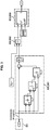
- the filtering step Ef is applied to the command in position resulting from step E3, so that a command in filtered position is obtained at the output.
- the filtering is carried out with a first order low pass filter, having a single cutoff frequency fc.
- the choice of the type of filter is based on the fact that the frequencies to be suppressed are much higher than the nominal behavior of the logic.
- Determining the cutoff frequency fc is an important condition for obtaining effective filtering that does not cripple the control process.
- the response time of the filter was chosen by a compromise between two constraints. Indeed, this response time must be high enough to eliminate a maximum of oscillations without slowing down the system to unacceptable proportions from the point of view of the thermal response of the casing. In fact, too low a frequency would filter the nominal value of the control and the control valve 20 would remain virtually stationary.
- the frequency fo of the micro-oscillations was also estimated, which made it possible to determine a lower limit of the response time, and therefore an upper limit for the cut-off frequency fc.
- a cutoff frequency fc between 0.05 and 0.15 Hz, or even 0.08 and 0.12 Hz or more broadly between 0.01 and 0.20Hz .
- the frequency fo is around 1 Hz, which is far enough from the previous upper bounds to ensure effective filtering.
- cut-off frequencies fc in the latter interval it is ensured to have response times lower than those of the housing 16.
- the addition of the filter slows down the system somewhat and it should preferably only be applied in relevant flight phases. In this case, it is only desirable to apply this filtering in cruising flight conditions, that is to say when the engine speed is in steady state (speed at which the oscillations are observed at the frequency fo).
- control valve 20 when the system requests a rapid reaction from the control valve 20, it is desired that the control is not slowed down by a filter (for example an action of the pilot, during take-off or landing or for example a sudden change environment).
- a filter for example an action of the pilot, during take-off or landing or for example a sudden change environment.
- this gradient is compared with a deactivation threshold value Sg. More precisely, to get rid of questions of signs, the absolute value of this gradient is compared with the deactivation threshold value Sg.
- the filtering step Ef is deactivated if the gradient is greater than or equal to said threshold Sg.
- a threshold value which is between 0.5 and 2.5% per second, that is to say that at one second interval, the command varies between 0.5 and 2.5% of its original value.
- the threshold value is 1% for 0.72 seconds, or 1.4% per second.
- An interval of 1 and 2% per second may also be suitable.
- a gradient greater than the threshold Sg means that it is not a micro-oscillation which is detected, but a relevant change for the system which can have an impact on the housing 16.
- the filtering stops and the system recovers its classic operation.
- the value analyzed is the control gradient and not the physical measurement given by the sensors: the solution would take filtering into account (since the control in position has been filtered) and would be too slow.
- the reactivation (or activation) of the filtering step is also done under condition using another sub-process, also represented in figure 3 .
- Step E63 is improperly represented on the figure 3 , since the drawn block outputs an activation condition, which is then preferably combined with the other activation conditions to effectively activate the filter.
- the filter can be re-engaged.
- the filtering step Ef is applied to the engine speed data from step E1, so that a command in the filtered position is again obtained at the output.
- the step of determining a flow rate control E2 is then carried out on the basis of the filtered data relating to the engine speed.
- Embodiments with activation and deactivation thresholds can also be implemented.
- step E3 It is also conceivable to apply the filtering step to the flow control resulting from step E2.
- the step of determining the command in position E3 is then carried out on the basis of filtered flow control data. This embodiment is illustrated in figure 5 .
- Embodiments with activation and deactivation thresholds can also be implemented.
Landscapes
- Engineering & Computer Science (AREA)
- Mechanical Engineering (AREA)
- General Engineering & Computer Science (AREA)
- Physics & Mathematics (AREA)
- Fluid Mechanics (AREA)
- Control Of Turbines (AREA)
Claims (12)
- Verfahren zum Steuern eines Steuerventils (20) einer Turbomaschine, wobei das Ventil zum Steuern des Spiels zwischen einer Turbinenschaufel und einem Gehäuse durch Einleiten von Luft über das Gehäuse dient, wobei die Turbomaschine im Motormodus mit einem Reiseflugwert (Vc) arbeitet und um ihren Reiseflugwert (Vc) schwankt,
wobei das Verfahren von einer Recheneinheit (40) durchgeführt wird, und
dadurch gekennzeichnet ist, dass es einen Bestimmungsschritt für das Steuerventil (20) einer von den Schwankungen des Motormodus um den Reiseflugwert (Vc) gefilterte Positionssteuerung umfasst. - Verfahren nach Anspruch 1, wobei das Filtern mit Hilfe eines Tiefpassfilters durchgeführt wird, von dem eine Kappungsfrequenz (fc) höher als eine der thermischen Antwortzeit des Gehäuses (16) zugeordnete Frequenz (fr) ist.
- Verfahren nach Anspruch 1 oder 2, wobei der Bestimmungsschritt die folgenden Unterschritte umfasst:- (E1) Empfangen der Daten, die den Motormodus der Turbomaschine quantifizieren,- (E2) Bestimmen einer Durchsatzsteuerung auf der Basis der den Motormodus quantifizierenden Daten,- (E3) Bestimmen einer Positionssteuerung auf der Basis der Durchsatzsteuerung, wobei die Positionssteuerung für das Steuerventil bestimmt ist,- (Ef) Filtern der Positionssteuerung, die aus dem Bestimmungsschritt der Positionssteuerung (E3) hervorgegangen ist.
- Verfahren nach Anspruch 2 oder 3, wobei der Tiefpassfilter ein Filter der ersten Ordnung ist.
- Verfahren nach einem der Ansprüche 2 bis 4, wobei das Steuerventil (20) zur Versorgung des Inneren eines Gehäuses (16) mit Luft bestimmt ist, um seine Ausdehnung zu ändern.
- Verfahren nach einem der Ansprüche 2 bis 5, wobei die Kappungsfrequenz (fc) zwischen 0,05 Hz und 0,15 Hz liegt.
- Verfahren nach einem der Ansprüche 2 bis 6, umfassend ein Unterverfahren des Deaktivierens des Filterschritts der Steuerung (Ef), der von der Recheneinheit (40) durchgeführt wird, wobei das Unterverfahren die folgenden Schritte umfasst:- (E51) Bestimmen des aus dem Bestimmungsschritt einer Positionssteuerung (E3) hervorgegangenen Gradienten der Positionssteuerung,- (E52) Vergleichen dieses Gradienten mit einem Deaktivierungsgrenzwert (Sg),- (E53) Deaktivieren des Filters, wenn der Gradient über dem Grenzwert (Sg) liegt.
- Verfahren nach einem der Ansprüche 2 bis 7, umfassend ein Unterverfahren des Aktivierens des Filterschritts (Ef), der von der Recheneinheit (40) durchgeführt wird, wobei das Unterverfahren die folgenden Schritte umfasst:- (E61) Bestimmen des aus dem Bestimmungsschritt einer Positionssteuerung (E3) hervorgegangenen Gradienten der Positionssteuerung,- (E62) Vergleichen dieses Gradienten mit einem Aktivierungsgrenzwert (Sg'),- (E63) Aktivieren des Filters, wenn der Gradient während mindestens einer Bestätigungsdauer (T) unter dem Grenzwert (Sg') liegt und vorzugsweise, wenn die Höhe, der Motormodus und das Mach ebenfalls jeweils einen bestimmten Wert bestätigen.
- Verfahren nach Anspruch 2, wobei der Bestimmungsschritt die folgenden Unterschritte umfasst:- (E1) Empfangen der Daten, die den Motormodus der Turbomaschine quantifizieren,- (Ef) Filtern über Daten der den Motormodus quantifizierenden Daten, die aus dem vorhergehenden Schritt hervorgegangen sind,- (E2, E3) Bestimmen einer Positionssteuerung, die für das Steuerventil (20) bestimmt ist.
- Verfahren nach einem der Ansprüche 1 bis 9, wobei das Filtern mit Hilfe eines Tiefpassfilters durchgeführt wird, von dem eine Kappungsfrequenz (fc) niedriger als eine Frequenz (fo) der Schwankungen des Motormodus um den Reiseflugwert (Vc) ist.
- System zum Steuern eines Steuerventils (20) einer Turbomaschine, die im Motormodus in einem Reiseflugwert (Vc) arbeitet, wobei das Steuerventil (20) zur Versorgung eines Gehäuses (16) mit Luft bestimmt ist, um seine Ausdehnung zu ändern, wobei das System ein Steuerventil und eine Recheneinheit (40) umfasst, umfassend einen Filterblock, der Schwankungen des Motormodus um den Reiseflugwert (Vc) filtert, wobei die Recheneinheit (40) ausgelegt ist, um das Verfahren nach einem der Ansprüche 1 bis 10 durchzuführen, wobei der Filterblock den Filterschritt durchführt.
- Turbomaschine, umfassend ein System nach Anspruch 11.
Applications Claiming Priority (2)
| Application Number | Priority Date | Filing Date | Title |
|---|---|---|---|
| FR1661340A FR3059042B1 (fr) | 2016-11-22 | 2016-11-22 | Procede de commande d'une vanne de turbomachine |
| PCT/FR2017/053207 WO2018096264A1 (fr) | 2016-11-22 | 2017-11-22 | Procédé de commande d'une vanne de turbomachine |
Publications (2)
| Publication Number | Publication Date |
|---|---|
| EP3545175A1 EP3545175A1 (de) | 2019-10-02 |
| EP3545175B1 true EP3545175B1 (de) | 2020-12-30 |
Family
ID=58347515
Family Applications (1)
| Application Number | Title | Priority Date | Filing Date |
|---|---|---|---|
| EP17811651.3A Active EP3545175B1 (de) | 2016-11-22 | 2017-11-22 | Verfahren zur steuerung eines turbomaschinenventils |
Country Status (5)
| Country | Link |
|---|---|
| US (1) | US10995628B2 (de) |
| EP (1) | EP3545175B1 (de) |
| CN (1) | CN110050106B (de) |
| FR (1) | FR3059042B1 (de) |
| WO (1) | WO2018096264A1 (de) |
Families Citing this family (1)
| Publication number | Priority date | Publication date | Assignee | Title |
|---|---|---|---|---|
| FR3097063B1 (fr) * | 2019-06-10 | 2021-05-28 | Safran Aircraft Engines | Procédé de détermination d’un modèle prédictif d’un rapport de pressions pour une turbomachine double flux |
Family Cites Families (14)
| Publication number | Priority date | Publication date | Assignee | Title |
|---|---|---|---|---|
| GB620318A (en) * | 1946-09-25 | 1949-03-23 | Harold William Shaw | An improved failure indicator for gas-turbine engines |
| US4304093A (en) * | 1979-08-31 | 1981-12-08 | General Electric Company | Variable clearance control for a gas turbine engine |
| US4573358A (en) * | 1984-10-22 | 1986-03-04 | Westinghouse Electric Corp. | Turbine blade vibration detection apparatus |
| US5012420A (en) * | 1988-03-31 | 1991-04-30 | General Electric Company | Active clearance control for gas turbine engine |
| US6231306B1 (en) * | 1998-11-23 | 2001-05-15 | United Technologies Corporation | Control system for preventing compressor stall |
| US6195982B1 (en) * | 1998-12-30 | 2001-03-06 | United Technologies Corporation | Apparatus and method of active flutter control |
| US6487491B1 (en) * | 2001-11-21 | 2002-11-26 | United Technologies Corporation | System and method of controlling clearance between turbine engine blades and case based on engine components thermal growth model |
| US7079957B2 (en) * | 2003-12-30 | 2006-07-18 | General Electric Company | Method and system for active tip clearance control in turbines |
| US7465145B2 (en) * | 2005-03-17 | 2008-12-16 | United Technologies Corporation | Tip clearance control system |
| US7650777B1 (en) * | 2008-07-18 | 2010-01-26 | General Electric Company | Stall and surge detection system and method |
| FR2939170B1 (fr) * | 2008-11-28 | 2010-12-31 | Snecma | Detection d'anomalie dans un moteur d'aeronef. |
| FR2997443B1 (fr) * | 2012-10-31 | 2015-05-15 | Snecma | Unite de commande et procede de pilotage de jeu en sommet d'aubes |
| US9266618B2 (en) * | 2013-11-18 | 2016-02-23 | Honeywell International Inc. | Gas turbine engine turbine blade tip active clearance control system and method |
| GB201507881D0 (en) * | 2015-05-08 | 2015-06-24 | Rolls Royce Plc | Turbine tip clearance |
-
2016
- 2016-11-22 FR FR1661340A patent/FR3059042B1/fr active Active
-
2017
- 2017-11-22 WO PCT/FR2017/053207 patent/WO2018096264A1/fr not_active Ceased
- 2017-11-22 US US16/463,002 patent/US10995628B2/en active Active
- 2017-11-22 EP EP17811651.3A patent/EP3545175B1/de active Active
- 2017-11-22 CN CN201780076407.4A patent/CN110050106B/zh active Active
Non-Patent Citations (1)
| Title |
|---|
| None * |
Also Published As
| Publication number | Publication date |
|---|---|
| US10995628B2 (en) | 2021-05-04 |
| FR3059042A1 (fr) | 2018-05-25 |
| CN110050106A (zh) | 2019-07-23 |
| CA3044429A1 (fr) | 2018-05-31 |
| EP3545175A1 (de) | 2019-10-02 |
| WO2018096264A1 (fr) | 2018-05-31 |
| US20190368368A1 (en) | 2019-12-05 |
| CN110050106B (zh) | 2022-02-08 |
| FR3059042B1 (fr) | 2020-07-17 |
Similar Documents
| Publication | Publication Date | Title |
|---|---|---|
| EP1607584B1 (de) | Vorrichtung und Verfahren zur Luftstromsteuerung in einem Triebwerk | |
| EP2486244B1 (de) | System zur steuerung der winkelposition von leitschaufeln und verfahren zur optimierung dieser winkelposition | |
| FR3007460A1 (fr) | Procede et systeme de demarrage d'une turbomachine d'aeronef par regulation en temps reel de debit d'air. | |
| FR3007461A1 (fr) | Procede et systeme de demarrage d'une turbomachine d'aeronef. | |
| EP3850202B1 (de) | Verfahren zur steuerung einer strömungsmaschine mit einem elektromotor | |
| FR2996254A1 (fr) | Methode de surveillance d'un defaut de poussee d'un turboreacteur d'aeronef | |
| EP2633169B1 (de) | Verfahren zur steuerung einer turbomaschine | |
| EP2864616B1 (de) | Verfahren zur einstellung eines referenzwerts eines parameters zur beeinflussung des schubs eines gasturbinentriebwerks | |
| CA2896695A1 (fr) | Procede et dispositif de detection de givrage d'une entree d'air d'un turbomoteur | |
| EP2989311B1 (de) | Verfahren und vorrichtung zur regelung und steuerung der kraftstoffmenge eines turbotriebwerks | |
| EP3959427B1 (de) | Verfahren zur regelung einer turbomaschine mit einer temporären leistungserhöhungsvorrichtung | |
| WO2021140292A1 (fr) | Procede et unite de commande pour le pilotage du jeu d'une turbine haute pression pour la reduction de l'effet de depassement egt | |
| CA2950347A1 (fr) | Procede et dispositif de controle d'une poussee d'un turboreacteur | |
| EP4251866A1 (de) | Verfahren zur steuerung eines turbinenmotors mit einem elektromotor | |
| EP3545175A1 (de) | Verfahren zur steuerung eines turbomaschinenventils | |
| FR2978994A1 (de) | ||
| CA3044429C (fr) | Procede de commande d'une vanne de turbomachine | |
| WO2020152425A1 (fr) | Procédé de surveillance de l'état de fonctionnement d'un système de positionnement d'organes à géométrie variable d'une turbomachine | |
| EP4669845A1 (de) | Vorrichtung und verfahren zur steuerung des ausschlags der drehzahl der hochdruckwelle eines turbomaschinenmotors | |
| FR3029570B1 (fr) | Dispositif et procede de regulation d'un moteur exploitant une mesure de poussee | |
| FR3043432A1 (fr) | Procede et dispositif d'ajustement de valeurs de consigne d'une pluralite de geometries variables determinees d'une turbomachine | |
| FR3040069A1 (fr) | Procede de detection d'une augmentation du regime d'une turbine basse pression d'un reacteur d'un aeronef au cours d'une phase de croisiere et dispositif et procede de regulation du debit d'air de refroidissement d'une turbine basse pression associes | |
| FR2960914A1 (fr) | Procede et dispositif de regulation du debit de carburant a injecter dans une chambre de combustion de turbomachine | |
| WO2025083350A1 (fr) | Systeme de commande d'une turbomachine hybridee par observateur a reconfiguration par detection de saturation de commande | |
| FR2965300A1 (fr) | Procede de commande pour turbomachine |
Legal Events
| Date | Code | Title | Description |
|---|---|---|---|
| STAA | Information on the status of an ep patent application or granted ep patent |
Free format text: STATUS: UNKNOWN |
|
| STAA | Information on the status of an ep patent application or granted ep patent |
Free format text: STATUS: THE INTERNATIONAL PUBLICATION HAS BEEN MADE |
|
| PUAI | Public reference made under article 153(3) epc to a published international application that has entered the european phase |
Free format text: ORIGINAL CODE: 0009012 |
|
| STAA | Information on the status of an ep patent application or granted ep patent |
Free format text: STATUS: REQUEST FOR EXAMINATION WAS MADE |
|
| 17P | Request for examination filed |
Effective date: 20190621 |
|
| AK | Designated contracting states |
Kind code of ref document: A1 Designated state(s): AL AT BE BG CH CY CZ DE DK EE ES FI FR GB GR HR HU IE IS IT LI LT LU LV MC MK MT NL NO PL PT RO RS SE SI SK SM TR |
|
| AX | Request for extension of the european patent |
Extension state: BA ME |
|
| DAV | Request for validation of the european patent (deleted) | ||
| DAX | Request for extension of the european patent (deleted) | ||
| GRAP | Despatch of communication of intention to grant a patent |
Free format text: ORIGINAL CODE: EPIDOSNIGR1 |
|
| STAA | Information on the status of an ep patent application or granted ep patent |
Free format text: STATUS: GRANT OF PATENT IS INTENDED |
|
| INTG | Intention to grant announced |
Effective date: 20201015 |
|
| GRAS | Grant fee paid |
Free format text: ORIGINAL CODE: EPIDOSNIGR3 |
|
| GRAA | (expected) grant |
Free format text: ORIGINAL CODE: 0009210 |
|
| STAA | Information on the status of an ep patent application or granted ep patent |
Free format text: STATUS: THE PATENT HAS BEEN GRANTED |
|
| AK | Designated contracting states |
Kind code of ref document: B1 Designated state(s): AL AT BE BG CH CY CZ DE DK EE ES FI FR GB GR HR HU IE IS IT LI LT LU LV MC MK MT NL NO PL PT RO RS SE SI SK SM TR |
|
| REG | Reference to a national code |
Ref country code: GB Ref legal event code: FG4D Free format text: NOT ENGLISH |
|
| REG | Reference to a national code |
Ref country code: AT Ref legal event code: REF Ref document number: 1350120 Country of ref document: AT Kind code of ref document: T Effective date: 20210115 |
|
| REG | Reference to a national code |
Ref country code: DE Ref legal event code: R096 Ref document number: 602017030643 Country of ref document: DE |
|
| REG | Reference to a national code |
Ref country code: IE Ref legal event code: FG4D Free format text: LANGUAGE OF EP DOCUMENT: FRENCH |
|
| REG | Reference to a national code |
Ref country code: SE Ref legal event code: TRGR |
|
| PG25 | Lapsed in a contracting state [announced via postgrant information from national office to epo] |
Ref country code: RS Free format text: LAPSE BECAUSE OF FAILURE TO SUBMIT A TRANSLATION OF THE DESCRIPTION OR TO PAY THE FEE WITHIN THE PRESCRIBED TIME-LIMIT Effective date: 20201230 Ref country code: FI Free format text: LAPSE BECAUSE OF FAILURE TO SUBMIT A TRANSLATION OF THE DESCRIPTION OR TO PAY THE FEE WITHIN THE PRESCRIBED TIME-LIMIT Effective date: 20201230 Ref country code: GR Free format text: LAPSE BECAUSE OF FAILURE TO SUBMIT A TRANSLATION OF THE DESCRIPTION OR TO PAY THE FEE WITHIN THE PRESCRIBED TIME-LIMIT Effective date: 20210331 Ref country code: NO Free format text: LAPSE BECAUSE OF FAILURE TO SUBMIT A TRANSLATION OF THE DESCRIPTION OR TO PAY THE FEE WITHIN THE PRESCRIBED TIME-LIMIT Effective date: 20210330 |
|
| REG | Reference to a national code |
Ref country code: AT Ref legal event code: MK05 Ref document number: 1350120 Country of ref document: AT Kind code of ref document: T Effective date: 20201230 |
|
| PG25 | Lapsed in a contracting state [announced via postgrant information from national office to epo] |
Ref country code: BG Free format text: LAPSE BECAUSE OF FAILURE TO SUBMIT A TRANSLATION OF THE DESCRIPTION OR TO PAY THE FEE WITHIN THE PRESCRIBED TIME-LIMIT Effective date: 20210330 Ref country code: LV Free format text: LAPSE BECAUSE OF FAILURE TO SUBMIT A TRANSLATION OF THE DESCRIPTION OR TO PAY THE FEE WITHIN THE PRESCRIBED TIME-LIMIT Effective date: 20201230 |
|
| REG | Reference to a national code |
Ref country code: NL Ref legal event code: MP Effective date: 20201230 |
|
| PG25 | Lapsed in a contracting state [announced via postgrant information from national office to epo] |
Ref country code: HR Free format text: LAPSE BECAUSE OF FAILURE TO SUBMIT A TRANSLATION OF THE DESCRIPTION OR TO PAY THE FEE WITHIN THE PRESCRIBED TIME-LIMIT Effective date: 20201230 |
|
| REG | Reference to a national code |
Ref country code: LT Ref legal event code: MG9D |
|
| PG25 | Lapsed in a contracting state [announced via postgrant information from national office to epo] |
Ref country code: LT Free format text: LAPSE BECAUSE OF FAILURE TO SUBMIT A TRANSLATION OF THE DESCRIPTION OR TO PAY THE FEE WITHIN THE PRESCRIBED TIME-LIMIT Effective date: 20201230 Ref country code: CZ Free format text: LAPSE BECAUSE OF FAILURE TO SUBMIT A TRANSLATION OF THE DESCRIPTION OR TO PAY THE FEE WITHIN THE PRESCRIBED TIME-LIMIT Effective date: 20201230 Ref country code: EE Free format text: LAPSE BECAUSE OF FAILURE TO SUBMIT A TRANSLATION OF THE DESCRIPTION OR TO PAY THE FEE WITHIN THE PRESCRIBED TIME-LIMIT Effective date: 20201230 Ref country code: RO Free format text: LAPSE BECAUSE OF FAILURE TO SUBMIT A TRANSLATION OF THE DESCRIPTION OR TO PAY THE FEE WITHIN THE PRESCRIBED TIME-LIMIT Effective date: 20201230 Ref country code: PT Free format text: LAPSE BECAUSE OF FAILURE TO SUBMIT A TRANSLATION OF THE DESCRIPTION OR TO PAY THE FEE WITHIN THE PRESCRIBED TIME-LIMIT Effective date: 20210430 Ref country code: SK Free format text: LAPSE BECAUSE OF FAILURE TO SUBMIT A TRANSLATION OF THE DESCRIPTION OR TO PAY THE FEE WITHIN THE PRESCRIBED TIME-LIMIT Effective date: 20201230 |
|
| PG25 | Lapsed in a contracting state [announced via postgrant information from national office to epo] |
Ref country code: AT Free format text: LAPSE BECAUSE OF FAILURE TO SUBMIT A TRANSLATION OF THE DESCRIPTION OR TO PAY THE FEE WITHIN THE PRESCRIBED TIME-LIMIT Effective date: 20201230 Ref country code: PL Free format text: LAPSE BECAUSE OF FAILURE TO SUBMIT A TRANSLATION OF THE DESCRIPTION OR TO PAY THE FEE WITHIN THE PRESCRIBED TIME-LIMIT Effective date: 20201230 |
|
| PG25 | Lapsed in a contracting state [announced via postgrant information from national office to epo] |
Ref country code: IS Free format text: LAPSE BECAUSE OF FAILURE TO SUBMIT A TRANSLATION OF THE DESCRIPTION OR TO PAY THE FEE WITHIN THE PRESCRIBED TIME-LIMIT Effective date: 20210430 |
|
| REG | Reference to a national code |
Ref country code: DE Ref legal event code: R097 Ref document number: 602017030643 Country of ref document: DE |
|
| PG25 | Lapsed in a contracting state [announced via postgrant information from national office to epo] |
Ref country code: AL Free format text: LAPSE BECAUSE OF FAILURE TO SUBMIT A TRANSLATION OF THE DESCRIPTION OR TO PAY THE FEE WITHIN THE PRESCRIBED TIME-LIMIT Effective date: 20201230 |
|
| PLBE | No opposition filed within time limit |
Free format text: ORIGINAL CODE: 0009261 |
|
| STAA | Information on the status of an ep patent application or granted ep patent |
Free format text: STATUS: NO OPPOSITION FILED WITHIN TIME LIMIT |
|
| PG25 | Lapsed in a contracting state [announced via postgrant information from national office to epo] |
Ref country code: DK Free format text: LAPSE BECAUSE OF FAILURE TO SUBMIT A TRANSLATION OF THE DESCRIPTION OR TO PAY THE FEE WITHIN THE PRESCRIBED TIME-LIMIT Effective date: 20201230 |
|
| 26N | No opposition filed |
Effective date: 20211001 |
|
| PG25 | Lapsed in a contracting state [announced via postgrant information from national office to epo] |
Ref country code: ES Free format text: LAPSE BECAUSE OF FAILURE TO SUBMIT A TRANSLATION OF THE DESCRIPTION OR TO PAY THE FEE WITHIN THE PRESCRIBED TIME-LIMIT Effective date: 20201230 |
|
| PG25 | Lapsed in a contracting state [announced via postgrant information from national office to epo] |
Ref country code: SI Free format text: LAPSE BECAUSE OF FAILURE TO SUBMIT A TRANSLATION OF THE DESCRIPTION OR TO PAY THE FEE WITHIN THE PRESCRIBED TIME-LIMIT Effective date: 20201230 |
|
| PG25 | Lapsed in a contracting state [announced via postgrant information from national office to epo] |
Ref country code: IS Free format text: LAPSE BECAUSE OF FAILURE TO SUBMIT A TRANSLATION OF THE DESCRIPTION OR TO PAY THE FEE WITHIN THE PRESCRIBED TIME-LIMIT Effective date: 20210430 |
|
| PG25 | Lapsed in a contracting state [announced via postgrant information from national office to epo] |
Ref country code: MC Free format text: LAPSE BECAUSE OF FAILURE TO SUBMIT A TRANSLATION OF THE DESCRIPTION OR TO PAY THE FEE WITHIN THE PRESCRIBED TIME-LIMIT Effective date: 20201230 |
|
| REG | Reference to a national code |
Ref country code: CH Ref legal event code: PL |
|
| PG25 | Lapsed in a contracting state [announced via postgrant information from national office to epo] |
Ref country code: LU Free format text: LAPSE BECAUSE OF NON-PAYMENT OF DUE FEES Effective date: 20211122 Ref country code: BE Free format text: LAPSE BECAUSE OF NON-PAYMENT OF DUE FEES Effective date: 20211130 |
|
| REG | Reference to a national code |
Ref country code: BE Ref legal event code: MM Effective date: 20211130 |
|
| PG25 | Lapsed in a contracting state [announced via postgrant information from national office to epo] |
Ref country code: LI Free format text: LAPSE BECAUSE OF NON-PAYMENT OF DUE FEES Effective date: 20211130 Ref country code: CH Free format text: LAPSE BECAUSE OF NON-PAYMENT OF DUE FEES Effective date: 20211130 |
|
| PG25 | Lapsed in a contracting state [announced via postgrant information from national office to epo] |
Ref country code: IE Free format text: LAPSE BECAUSE OF NON-PAYMENT OF DUE FEES Effective date: 20211122 |
|
| PG25 | Lapsed in a contracting state [announced via postgrant information from national office to epo] |
Ref country code: NL Free format text: LAPSE BECAUSE OF NON-PAYMENT OF DUE FEES Effective date: 20201230 Ref country code: CY Free format text: LAPSE BECAUSE OF FAILURE TO SUBMIT A TRANSLATION OF THE DESCRIPTION OR TO PAY THE FEE WITHIN THE PRESCRIBED TIME-LIMIT Effective date: 20201230 |
|
| PG25 | Lapsed in a contracting state [announced via postgrant information from national office to epo] |
Ref country code: SM Free format text: LAPSE BECAUSE OF FAILURE TO SUBMIT A TRANSLATION OF THE DESCRIPTION OR TO PAY THE FEE WITHIN THE PRESCRIBED TIME-LIMIT Effective date: 20201230 Ref country code: HU Free format text: LAPSE BECAUSE OF FAILURE TO SUBMIT A TRANSLATION OF THE DESCRIPTION OR TO PAY THE FEE WITHIN THE PRESCRIBED TIME-LIMIT; INVALID AB INITIO Effective date: 20171122 |
|
| PG25 | Lapsed in a contracting state [announced via postgrant information from national office to epo] |
Ref country code: MK Free format text: LAPSE BECAUSE OF FAILURE TO SUBMIT A TRANSLATION OF THE DESCRIPTION OR TO PAY THE FEE WITHIN THE PRESCRIBED TIME-LIMIT Effective date: 20201230 |
|
| PG25 | Lapsed in a contracting state [announced via postgrant information from national office to epo] |
Ref country code: MT Free format text: LAPSE BECAUSE OF FAILURE TO SUBMIT A TRANSLATION OF THE DESCRIPTION OR TO PAY THE FEE WITHIN THE PRESCRIBED TIME-LIMIT Effective date: 20201230 |
|
| PG25 | Lapsed in a contracting state [announced via postgrant information from national office to epo] |
Ref country code: TR Free format text: LAPSE BECAUSE OF FAILURE TO SUBMIT A TRANSLATION OF THE DESCRIPTION OR TO PAY THE FEE WITHIN THE PRESCRIBED TIME-LIMIT Effective date: 20201230 |
|
| PGFP | Annual fee paid to national office [announced via postgrant information from national office to epo] |
Ref country code: DE Payment date: 20251118 Year of fee payment: 9 |
|
| PGFP | Annual fee paid to national office [announced via postgrant information from national office to epo] |
Ref country code: GB Payment date: 20251125 Year of fee payment: 9 |
|
| PGFP | Annual fee paid to national office [announced via postgrant information from national office to epo] |
Ref country code: IT Payment date: 20251128 Year of fee payment: 9 |
|
| PGFP | Annual fee paid to national office [announced via postgrant information from national office to epo] |
Ref country code: FR Payment date: 20251125 Year of fee payment: 9 |
|
| PGFP | Annual fee paid to national office [announced via postgrant information from national office to epo] |
Ref country code: SE Payment date: 20251119 Year of fee payment: 9 |