EP3544774B1 - Dichtungs- und führungssystem für eine verpackungsmaschine - Google Patents
Dichtungs- und führungssystem für eine verpackungsmaschine Download PDFInfo
- Publication number
- EP3544774B1 EP3544774B1 EP17822446.5A EP17822446A EP3544774B1 EP 3544774 B1 EP3544774 B1 EP 3544774B1 EP 17822446 A EP17822446 A EP 17822446A EP 3544774 B1 EP3544774 B1 EP 3544774B1
- Authority
- EP
- European Patent Office
- Prior art keywords
- disk
- movement actuating
- actuating element
- movement
- housing
- Prior art date
- Legal status (The legal status is an assumption and is not a legal conclusion. Google has not performed a legal analysis and makes no representation as to the accuracy of the status listed.)
- Active
Links
Images




Classifications
-
- B—PERFORMING OPERATIONS; TRANSPORTING
- B25—HAND TOOLS; PORTABLE POWER-DRIVEN TOOLS; MANIPULATORS
- B25J—MANIPULATORS; CHAMBERS PROVIDED WITH MANIPULATION DEVICES
- B25J21/00—Chambers provided with manipulation devices
-
- B—PERFORMING OPERATIONS; TRANSPORTING
- B65—CONVEYING; PACKING; STORING; HANDLING THIN OR FILAMENTARY MATERIAL
- B65B—MACHINES, APPARATUS OR DEVICES FOR, OR METHODS OF, PACKAGING ARTICLES OR MATERIALS; UNPACKING
- B65B51/00—Devices for, or methods of, sealing or securing package folds or closures; Devices for gathering or twisting wrappers, or necks of bags
- B65B51/10—Applying or generating heat or pressure or combinations thereof
- B65B51/16—Applying or generating heat or pressure or combinations thereof by rotary members
-
- B—PERFORMING OPERATIONS; TRANSPORTING
- B25—HAND TOOLS; PORTABLE POWER-DRIVEN TOOLS; MANIPULATORS
- B25J—MANIPULATORS; CHAMBERS PROVIDED WITH MANIPULATION DEVICES
- B25J21/00—Chambers provided with manipulation devices
- B25J21/005—Clean rooms
-
- B—PERFORMING OPERATIONS; TRANSPORTING
- B65—CONVEYING; PACKING; STORING; HANDLING THIN OR FILAMENTARY MATERIAL
- B65B—MACHINES, APPARATUS OR DEVICES FOR, OR METHODS OF, PACKAGING ARTICLES OR MATERIALS; UNPACKING
- B65B55/00—Preserving, protecting or purifying packages or package contents in association with packaging
-
- B—PERFORMING OPERATIONS; TRANSPORTING
- B65—CONVEYING; PACKING; STORING; HANDLING THIN OR FILAMENTARY MATERIAL
- B65B—MACHINES, APPARATUS OR DEVICES FOR, OR METHODS OF, PACKAGING ARTICLES OR MATERIALS; UNPACKING
- B65B65/00—Details peculiar to packaging machines and not otherwise provided for; Arrangements of such details
- B65B65/02—Driving gear
Definitions
- the present invention falls within the technical field of automatic machines for packaging products.
- the invention relates to a sealing and guiding system for a packaging machine.
- Said systems are generally used in machines for packaging products such as those in the pharmaceutical, foodstuff or cosmetic fields.
- packaging machines used in these fields must perform product processing in highly hygienic if not aseptic conditions, and are designed to avoid, as much as possible, any type of contamination of the processed products.
- the packaging machines dedicated to the aforementioned fields, at the processing stations comprise a system that separates two distinct zones: a processing zone, where the products on which the processing means operate are conveyed and must meet certain hygiene requirements, and an activation zone in which actuating mechanisms for means which operate on the products in the processing zone are provided.
- the above described system must therefore guarantee the hermetic seal of the processing zone and, at the same time, allow the movement of the operating means between the two zones.
- the above-mentioned system in detail, comprises a separating wall or an insulating barrier, through which a shaft passes from the activation zone and develops in the processing zone and which carries the processing means.
- the shaft is moved by suitable actuators, arranged in the activation zone.
- the shaft only has to perform rotational movements around its axis, there is a reduced risk of contamination from the activation zone towards the processing zone, as it is possible to guarantee the hermetic seal of the processing zone due to the presence of sealing gaskets suitably arranged around the same movement actuating shaft.
- the system comprises seals formed by an elastic bellow, through which the translating shaft can be moved.
- this system has drawbacks.
- the elastic material with which the bellow is made for example rubber, may be subject to damage or breakage without showing direct evidence, thus causing a probable contamination of the processing zone.
- These breakages may be due to mechanical wear and to damage due to particularly intense washing (e.g. from steam jets or other hot and/or pressurized substances).
- Patent Application EP2801267A2 discloses a device for transferring rod-shaped smoking articles.
- Patent US5575176A discloses an apparatus or manipulator for positioning objects within a sealed chamber.
- the object of the present invention is to overcome the drawbacks mentioned above. This object is achieved by proposing a sealing and guiding system according to the appended claims.
- the invention is able to avoid the transfer of contaminants and/or bacteria from the activation zone, in which the mechanisms and the actuators are arranged, towards the processing zone, where the processing of the products takes place, without compromising, among other things, the productivity of the machine.
- a further advantage consists in the fact that the solution proposed with the invention is easily cleanable, and resistant even to aggressive washing.
- the processing zone S is the zone of the machine M in which the products are conveyed to be processed
- the activation zone N is the zone of the machine M in which the activation mechanisms for the means which operate on the products in the processing zone S (as will be better clarified with the following discussion).
- the processing zone S must comply with certain hygiene requirements, to avoid contamination of the processed products. In the case of machines in the pharmaceutical field, the processing zone S is in sterile conditions.
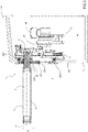
- the system 1 comprises: a separating wall 2 for separating the processing zone S from the activation zone N of the packaging machine M; at least one movement actuating element 3 (shown in the figures in an exemplary and partial way as a shaft 3), that extends from the activation zone N to the processing zone S, crossing the separating wall 2.
- the movement actuating element 3 has a respective portion 30 arranged in the processing zone S, and a respective portion 300 arranged in the activation zone N (the latter is particularly visible in figure 5 ).
- the system 1 further comprises: movement actuating means 4 arranged in the activation zone N, for moving the movement actuating element 3 at least along a first direction D1 (indicated by way of example in the figures), transversely (i.e. non-parallel) to the respective axis H.
- first direction D1 can be parallel to the separating wall 2, and in the illustrated embodiment it is perpendicular to the axis H of the movement actuating element 3.
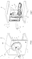
- the separating wall 2 comprises: a first part 20 comprising, in turn, a first housing delimited by a first circular edge; and a first disk 21, that can be inserted in the first housing, so as to be rotatable with respect to the first part 20.
- the first disk 21 comprises, in turn, a second housing delimited by a second circular edge, eccentric with respect to the center O of the first disk 21.
- the separating wall 2 further comprises a second disk 22, that can be inserted in the second housing so as to be rotatable with respect to the first disk 21.
- the second disk 22 comprises, in turn, a third housing delimited by a third circular edge, that is eccentric with respect to the center P of the second disk 22, with the movement actuating element 3 which is inserted in the third housing.
- the movement actuating element 3 passes through the separating wall 2 at the third housing of the second disk 22, to which it is constrained (in particular to which it is rotatably connected), so as to be eccentric with respect to the center P of the second disk 22.
- the system 1 comprises rotary sealing means 200, 210, 220, arranged at the first housing, at the second housing and at the third housing, allowing the sealing between the processing zone S and the activation zone N and the relative rotation of the first disk 21, of the second disk 22 and of the movement actuating element 3.
- the first part 20 of the separating wall 2 is fixed (forming a frame).
- the axes of the first disk 21 and of the second disk 22 are parallel to each other, and the first direction D1 lies on a plane perpendicular to the rotation axes of the first disk 21 and of the second disk 22.
- the axis H of the movement actuating element 3 (which is a shaft in the illustrated solutions) is parallel to the rotation axes of the first disk 21 and of the second disk 22. Therefore, in this specific case, the first direction D1 is also perpendicular to the axis H of the movement actuating element.
- the rotation axis of the third rotoidal torque formed between the movement actuating element 3 and the second disk 22 is not necessarily coincident with the axis of the movement actuating element 3.
- the condition sufficient for the operation of the system is that the rotational axes of the first rotoidal torque, of the second rotoidal torque and of the third rotoidal torque described above are parallel to each other.
- the system 1 proposed with the invention can guarantee the sealing of the processing zone S, while allowing the motion of the movement actuating element 3 in the aforementioned first direction D1, without the need to provide "bellow type” systems or the arrangement of suction means, as was instead necessary with systems of known type. This is guaranteed by the fact that, with the system 1, the movement actuating element 3 is not subjected to axial translations.
- separating wall used in the present discussion, it is not intended exclusively a flat wall as illustrated in the attached examples, but the expression is intended to be extended to any element (or plurality of elements) of any geometry (also not uniform), of any material and having any inclination in space, which is adapted to separate two adjacent environments from each other.
- the rotary sealing means 200, 210, 220 (better seen in Figure 5 , illustrated only schematically and indicatively in Figures 1 , 3 , 6 , 8 ) comprise a first sealing and supporting ring 200, arranged between the first part 20 and the first disk 21, at the first housing (i.e. at the first circular edge); a second sealing and supporting ring 210, arranged between the first disk 21 and the second disk 22, at the second housing (i.e. at the second circular edge); and a third sealing and supporting ring 220, arranged between the second disk 22 and the movement actuating element 3, at the third housing (i.e. at the third circular edge).
- the rotary sealing means comprise roller bearings or bushings (not indicated in the attached figures), associated with the aforementioned sealing and supporting rings 200, 210, 220, arranged in the activation zone N, to allow mutual rotation between the parts.
- the rotary sealing means 200, 210, 220 therefore, guarantee the hermetic seal between the processing zone S and the activation zone N, as well as the possible movement of the components of the system 1.
- the system 1 comprises guiding means 5, arranged in the activation zone N, connected to the movement actuating element 3 for guiding the movement actuating element 3 at least along the aforementioned first direction D1, transverse to the respective axis H.
- the guiding means 5 offer support and stability to the element 3 during the relative movement.
- the guiding means comprise a slide 5.
- the guiding means 5 and the movement actuating means 4 are arranged for guiding and moving the movement actuating element 3 also along a second direction, transverse to the respective axis H and different from the first direction D1.
- the guiding means 5 and the movement actuating means 4 are arranged for guiding and moving the movement actuating element 3 so that it can perform a "L-like" trajectory in the processing zone S, or a curvilinear or oblique trajectory with respect to the first direction D1 (situation not illustrated).
- the guiding means 5 and the movement actuating means 4 can be arranged for guiding and moving the movement actuating element 3 also along other directions different from what has been described, provided that said movement directions lie on planes perpendicular to the rotation axes of the first disk 21 and of the second disk 22 (i.e. to the rotation axes of the first rotoidal torque and of the second rotoidal torque), as well as to the rotation axis of the third rotoidal torque.
- the movement actuating means 4 are arranged to act directly on the movement actuating element 3 to move it along the first direction D1, with the first disk 21 and the second disk 22, which rotate as a consequence of the movement of the movement actuating element 3.
- the movement actuating means 4 comprise a motor 40 and a connecting rod-crank system 41, 42 moved by the motor 40 and connected to the movement actuating element 3.
- the movement actuating means 4 are arranged to act on the first disk 21 and on the second disk 22 to indirectly move the movement actuating element 3 along the first direction D1.
- the movement actuating means 4 comprise a first motor 421 and a second motor 422, arranged to directly move the first disk 21 and the second disk 22, respectively.
- respective cogged ends E1, E2 in application formed, for example, by cogged belts or wheels
- the first disk 21 and the second disk 22 have cogged edges B1, B2 arranged in the activation zone N, capable of meshing respectively with the cogged end E1 of the first motor 421 and with the cogged end E2 of the second motor 422, so as to transfer the rotation movement from the two motors 421, 422 to the two disks 21, 22.
- the system 1 comprises constraining means (not illustrated) to prevent rotation of the movement actuating element 3.
- the rotation of the movement actuating element 3 can, in any case, be actuated independently and controlled by suitable control means not illustrated, arranged in the activation zone.
- the movement actuating means 4 can comprise any other system suitable for moving the element 3 at least along the aforementioned first direction D1.
- the movement actuating element 3 can be shaped to define on the inside thereof a housing 31, communicating with the activation zone N, which can be used for different purposes, as will be explained in the following.
- the movement actuating element 3, at the respective portion 30 arranged in the processing zone S, carries operating means (not illustrated), to act in the processing zone S.
- Said operating means can be formed by at least a clamp or a suction cup, or by a combination of different elements.
- the system 1 can further comprise control means (not illustrated), arranged within the housing 31 of the movement actuating element 3, and which develop from the activation zone N, to control the operating means independently of the movement of the element 3 itself.
- the control means can be arranged to activate the opening and closing of a clamp or the action of a suction cup.
- a mechanism for moving the operating means can be arranged, which, for example, allows to rotate the latter in two opposite rotation directions around a rotation axis parallel to or coinciding with the axis H of the movement actuating element 3.
- the housing 31 defined within the movement actuating element 3 can be used as a passage for conveying into the processing zone S processing liquids or gases (nitrogen, compressed air, vacuum, etc.) or electrical connections from the activation zone N.
- the scope of protection of the invention also comprises the case in which the first disk comprises two second housings, within which two second disks are arranged, to each of which a corresponding movement actuating element is rotatably constrained (situation not illustrated).
- the movement of the two second disks can be carried out synchronously or independently, i.e. using the same actuator or two separate actuators.
- the first disk is provided with two second housings, within which two second disks are arranged, mutually constrained, and there is only one movement actuating element fixed to one of the two second disks.
- the second disk to which the movement actuating element is not constrained can act as a support, for example, for a support element (e.g. a sleeve) fixed thereto and which protrudes only in the processing zone (without therefore also affecting the activation zone).
- This support element can be useful to facilitate operations in the processing zone; in particular, the support element can be connected to the movement actuating element to form a kinematic mechanism which follows the movement of the whole system 1 and which can be used to support suitable means, which operate in the processing zone (e.g. to ensure, in an optimal manner, support to a tray).
- the invention further relates to a packaging machine M, only partially illustrated in the attached figures.
- the machine comprises a processing zone S, in which products to be packaged are conveyed (i.e. filled, capped, etc.).
- the machine M further comprises an activation zone N, arranged adjacent to the processing zone S, and a sealing and guiding system 1 according to one of the embodiments described above.
- the separating wall 2 of the abovementioned system 1 is arranged between the processing zone S and the activation zone N, as previously described.
- the packaging machine M can, for example, be an automatic machine used in fields such as foodstuffs (for example, a machine for packaging yogurt jars), pharmaceutical (e.g. machine for filling vials or flasks), cosmetic (e.g. machine for packaging tubes of cream products) or in any other field where sterility, high hygiene or in any case a clear separation between two environments with different requirements (e.g. applications in modified atmospheres) is required.
- foodstuffs for example, a machine for packaging yogurt jars
- pharmaceutical e.g. machine for filling vials or flasks
- cosmetic e.g. machine for packaging tubes of cream products
- any other field where sterility, high hygiene or in any case a clear separation between two environments with different requirements (e.g. applications in modified atmospheres) is required.
Landscapes
- Engineering & Computer Science (AREA)
- Mechanical Engineering (AREA)
- Robotics (AREA)
- Filling Of Jars Or Cans And Processes For Cleaning And Sealing Jars (AREA)
- Package Closures (AREA)
- Containers And Plastic Fillers For Packaging (AREA)
- Basic Packing Technique (AREA)
Claims (11)
- Abdicht- und Führungssystem (1) für eine Verpackungsmaschine (M) umfassend eine Verarbeitungszone (S) zum Aufnehmen zu verarbeitender Produkte und eine Aktivierungszone (N), die zueinander benachbart sind;wobei das System (1) umfasst: eine Trennwand (2) zum Trennen der Verarbeitungszone (S) von der Aktivierungszone (N); wenigstens ein Bewegungsbetätigungselement (3), das sich von der Aktivierungszone (N) zu der Verarbeitungszone (S) erstreckt, die Trennwand (2) durchquert und eine Längserstreckungssachse (H) aufweist; Bewegungsbetätigungsmittel (4), die in der Aktivierungszone (N) angeordnet sind, um das Bewegungsbetätigungselement (3) wenigstens entlang einer ersten Richtung (D1) quer zu der jeweiligen Achse (H) zu bewegen;wobei das Bewegungsbetätigungselement (3) bei dem System (1) keinen axialen Translationen ausgesetzt ist;dadurch gekennzeichnet, dass:
die Trennwand (2) umfasst:- einen ersten Teil (20), der wenigstens ein erstes Gehäuse umfasst, das durch einen ersten kreisförmigen Rand begrenzt ist;- wenigstens eine erste Scheibe (21), die so in das erste Gehäuse eingeführt werden kann, dass sie in Bezug auf den ersten Teil (20) drehbar ist; wobei die erste Scheibe (21) ihrerseits wenigstens ein zweites Gehäuse umfasst, das durch einen zweiten kreisförmigen Rand begrenzt ist, der in Bezug auf den Mittelpunkt (O) der ersten Scheibe (21) exzentrisch ist;- wenigstens eine zweite Scheibe (22), die so in das zweite Gehäuse eingeführt werden kann, dass sie in Bezug auf die erste Scheibe (21) drehbar ist; wobei die zweite Scheibe (22) ihrerseits ein drittes Gehäuse umfasst, das durch einen dritten kreisförmigen Rand begrenzt ist, der mit dem Bewegungsbetätigungselement (3), das in das dritte Gehäuse eingeführt ist, in Bezug auf den Mittelpunkt (P) der zweiten Scheibe (22) exzentrisch ist;und dadurch, dass das System (1) Drehabdichtmittel (200, 210, 220) umfasst, die bei dem ersten Gehäuse, bei dem zweiten Gehäuse und bei dem dritten Gehäuse angeordnet sind, die die Abdichtung zwischen der Verarbeitungszone (S) und der Aktivierungszone (N) und die Relativdrehung der ersten Scheibe (21), der zweiten Scheibe (22) und des Bewegungsbetätigungselements (3) ermöglichen. - System nach Anspruch 1, wobei die Bewegungsbetätigungsmittel (4) für die direkte Wirkung auf das Bewegungsbetätigungselement (3) angeordnet sind, um es mit der ersten Scheibe (21) und mit der zweiten Scheibe (22), die sich wegen der Bewegung des Bewegungsbetätigungselements (3) drehen, entlang der ersten Richtung (D1) zu bewegen.
- System (1) nach Anspruch 2, wobei die Bewegungsbetätigungsmittel (4) einen Motor (40) und ein Stangen-Kurbel-System (41, 42), das mit dem Bewegungsbetätigungselement (3) verbunden ist, umfassen.
- System (1) nach Anspruch 1, wobei die Bewegungsbetätigungsmittel (4) dafür ausgelegt sind, auf die erste Scheibe (21) und auf die zweite Scheibe (22) zu wirken, um das Bewegungsbetätigungselement (3) indirekt entlang der ersten Richtung (D1) zu bewegen.
- System (1) nach Anspruch 4, wobei die Bewegungsbetätigungsmittel (4) einen ersten Motor (421) und einen zweiten Motor (422), die für die direkte Bewegung der ersten Scheibe (21) bzw. der zweiten Scheibe (22) angeordnet sind, umfassen; wobei der erste Motor (421) und der zweite Motor (422) jeweils Zahnradenden (E1, E2) umfassen; und wobei die erste Scheibe (21) und die zweite Scheibe (22) jeweils Zahnradränder (B1, B2) umfassen, die bei der Aktivierungszone (N) angeordnet sind, die dafür geeignet sind, mit dem Zahnradende (E1) des ersten Motors (421) bzw. mit dem Zahnradende (E2) des zweiten Motors (422) ineinanderzugreifen.
- System (1) nach einem der vorhergehenden Ansprüche 1 bis 5, das ferner Führungsmittel (5) umfasst, die bei der Aktivierungszone (N) angeordnet sind, die mit dem Bewegungsbetätigungselement (3) verbunden sind, um das Bewegungsbetätigungselement (3) wenigstens entlang der ersten Richtung (D1) quer zu der jeweiligen Achse (H) zu führen.
- System (1) nach Anspruch 6, wobei die Führungsmittel (5) und die Bewegungsbetätigungsmittel (4) dafür ausgelegt sind, das Bewegungsbetätigungselement (3) außerdem entlang einer zweiten Richtung, quer zu der jeweiligen Achse (H) und verschieden von der ersten Richtung (D1), zu führen und zu bewegen.
- System (1) nach einem der vorhergehenden Ansprüche 1 bis 7, wobei das Bewegungsbetätigungselement (3) so geformt ist, dass es auf seiner Innenseite ein Gehäuse (31) definiert, das mit der Aktivierungszone (N) in Verbindung steht.
- System (1) nach Anspruch 8, wobei das Bewegungsbetätigungselement (3) bei einem jeweiligen Abschnitt (30), der in der Verarbeitungszone (S) angeordnet ist, Arbeitsmittel trägt, um in der Verarbeitungszone (S) zu arbeiten; wobei das System (1) ferner Steuermittel umfasst, die innerhalb des Gehäuses (31) des Bewegungsbetätigungselements (3) angeordnet sind, um die Arbeitsmittel unabhängig von der Bewegung des Elements (3) selbst zu steuern.
- System (1) nach Anspruch 8 oder 9, wobei das Gehäuse (31) des Bewegungsbetätigungselements (3) einen Durchlass zum Befördern von Verarbeitungsflüssigkeiten oder Verarbeitungsgasen oder elektrischen Verbindungen in die Verarbeitungszone (S) bildet.
- Verpackungsmaschine (M), umfassend:eine Verarbeitungszone (S), in der zu verpackende Produkte befördert werden;eine Aktivierungszone (N), die benachbart zu der Verarbeitungszone (S) angeordnet ist;und ein Abdicht- und Führungssystem (1) nach einem der vorhergehenden Ansprüche 1 bis 10.
Applications Claiming Priority (2)
| Application Number | Priority Date | Filing Date | Title |
|---|---|---|---|
| IT102016000118480A IT201600118480A1 (it) | 2016-11-23 | 2016-11-23 | Sistema di tenuta e di guida per una macchina confezionatrice |
| PCT/IB2017/057326 WO2018096465A1 (en) | 2016-11-23 | 2017-11-22 | Sealing and guiding system for a packaging machine |
Publications (2)
| Publication Number | Publication Date |
|---|---|
| EP3544774A1 EP3544774A1 (de) | 2019-10-02 |
| EP3544774B1 true EP3544774B1 (de) | 2023-01-04 |
Family
ID=58266156
Family Applications (1)
| Application Number | Title | Priority Date | Filing Date |
|---|---|---|---|
| EP17822446.5A Active EP3544774B1 (de) | 2016-11-23 | 2017-11-22 | Dichtungs- und führungssystem für eine verpackungsmaschine |
Country Status (4)
| Country | Link |
|---|---|
| US (1) | US11111042B2 (de) |
| EP (1) | EP3544774B1 (de) |
| IT (1) | IT201600118480A1 (de) |
| WO (1) | WO2018096465A1 (de) |
Family Cites Families (5)
| Publication number | Priority date | Publication date | Assignee | Title |
|---|---|---|---|---|
| US5575176A (en) * | 1994-12-30 | 1996-11-19 | Rohrs; Henry W. | Three-dimensional positioning device |
| US6802203B1 (en) * | 2002-07-18 | 2004-10-12 | Warn Industries | Rotary seal testing machine |
| US8720666B2 (en) * | 2012-04-16 | 2014-05-13 | The Procter & Gamble Company | Apparatuses for transferring discrete articles |
| US8820513B2 (en) * | 2012-04-16 | 2014-09-02 | The Procter & Gamble Company | Methods for transferring discrete articles |
| DE102013104708B4 (de) * | 2013-05-07 | 2016-05-19 | Mts Tobacco S.A. | Vorrichtung zum Übergeben von stabförmigen Rauchartikeln |
-
2016
- 2016-11-23 IT IT102016000118480A patent/IT201600118480A1/it unknown
-
2017
- 2017-11-22 WO PCT/IB2017/057326 patent/WO2018096465A1/en not_active Ceased
- 2017-11-22 EP EP17822446.5A patent/EP3544774B1/de active Active
- 2017-11-22 US US16/461,399 patent/US11111042B2/en active Active
Also Published As
| Publication number | Publication date |
|---|---|
| US20200055624A1 (en) | 2020-02-20 |
| EP3544774A1 (de) | 2019-10-02 |
| IT201600118480A1 (it) | 2018-05-23 |
| US11111042B2 (en) | 2021-09-07 |
| WO2018096465A1 (en) | 2018-05-31 |
Similar Documents
| Publication | Publication Date | Title |
|---|---|---|
| US9567165B2 (en) | Transport device for containers | |
| JP4632560B2 (ja) | 三次元空間内で製品を操作するロボット | |
| US11760616B2 (en) | Capping machine for applying capsules on respective containers in aseptic or ultraclean conditions | |
| CN104441579B (zh) | 用于使塑料型胚成形的具有洁净室的装置 | |
| US9027732B2 (en) | Unit for transferring and up-ending sealed packages of pourable food products | |
| CN102529070A (zh) | 净化室内的传送星形轮 | |
| US11111042B2 (en) | Sealing and guiding system for a packaging machine | |
| US3797537A (en) | No-can no-fill feeding star wheel | |
| EP3741732A1 (de) | Glasformmaschine mit einer kolbenstation und verfahren | |
| US20090205289A1 (en) | Apparatus for ring-sealing closure elements on containers | |
| GB2591071A (en) | End effector | |
| WO1981000553A1 (fr) | Mecanisme de transport a vitesse constante | |
| EP1748929B1 (de) | Trennstruktur zur isolierung eines begrenzten raums von der äusseren umgebung | |
| US20260042621A1 (en) | Handling apparatus for containers, in particular pharmaceutical containers, system for processing such containers, and use of a handling apparatus | |
| US12240648B2 (en) | Feeding unit for a manufacturing machine and related feeding method | |
| EP3222540A1 (de) | Vorrichtung für elektronenstrahlsterilisation | |
| EP4705224A1 (de) | Isolierter verschliesskopf | |
| CN210479160U (zh) | 一种用于阿哌沙班及其中间体制备的装置 | |
| HU227146B1 (en) | Packaging machine | |
| WO2026019385A1 (en) | Mechanism that provides lowering and lifting movement to an object | |
| EP1201573A1 (de) | Vorrichtung zur Positionierung von Kunststoffbehältern | |
| GB2584003A (en) | End effector carriage for delta robot | |
| EP2364266A1 (de) | Einstellvorrichtung und solch eine einstellvorrichtung umfassende verpackungsmaschine |
Legal Events
| Date | Code | Title | Description |
|---|---|---|---|
| STAA | Information on the status of an ep patent application or granted ep patent |
Free format text: STATUS: UNKNOWN |
|
| STAA | Information on the status of an ep patent application or granted ep patent |
Free format text: STATUS: THE INTERNATIONAL PUBLICATION HAS BEEN MADE |
|
| PUAI | Public reference made under article 153(3) epc to a published international application that has entered the european phase |
Free format text: ORIGINAL CODE: 0009012 |
|
| STAA | Information on the status of an ep patent application or granted ep patent |
Free format text: STATUS: REQUEST FOR EXAMINATION WAS MADE |
|
| 17P | Request for examination filed |
Effective date: 20190509 |
|
| AK | Designated contracting states |
Kind code of ref document: A1 Designated state(s): AL AT BE BG CH CY CZ DE DK EE ES FI FR GB GR HR HU IE IS IT LI LT LU LV MC MK MT NL NO PL PT RO RS SE SI SK SM TR |
|
| AX | Request for extension of the european patent |
Extension state: BA ME |
|
| DAV | Request for validation of the european patent (deleted) | ||
| DAX | Request for extension of the european patent (deleted) | ||
| GRAP | Despatch of communication of intention to grant a patent |
Free format text: ORIGINAL CODE: EPIDOSNIGR1 |
|
| STAA | Information on the status of an ep patent application or granted ep patent |
Free format text: STATUS: GRANT OF PATENT IS INTENDED |
|
| RIC1 | Information provided on ipc code assigned before grant |
Ipc: B65B 65/02 20060101ALI20220711BHEP Ipc: B65B 55/00 20060101ALI20220711BHEP Ipc: B65B 55/02 20060101ALI20220711BHEP Ipc: B23Q 11/08 20060101ALI20220711BHEP Ipc: B23Q 1/54 20060101ALI20220711BHEP Ipc: B25J 21/00 20060101AFI20220711BHEP |
|
| INTG | Intention to grant announced |
Effective date: 20220727 |
|
| GRAS | Grant fee paid |
Free format text: ORIGINAL CODE: EPIDOSNIGR3 |
|
| GRAA | (expected) grant |
Free format text: ORIGINAL CODE: 0009210 |
|
| STAA | Information on the status of an ep patent application or granted ep patent |
Free format text: STATUS: THE PATENT HAS BEEN GRANTED |
|
| AK | Designated contracting states |
Kind code of ref document: B1 Designated state(s): AL AT BE BG CH CY CZ DE DK EE ES FI FR GB GR HR HU IE IS IT LI LT LU LV MC MK MT NL NO PL PT RO RS SE SI SK SM TR |
|
| REG | Reference to a national code |
Ref country code: GB Ref legal event code: FG4D |
|
| REG | Reference to a national code |
Ref country code: CH Ref legal event code: EP |
|
| REG | Reference to a national code |
Ref country code: AT Ref legal event code: REF Ref document number: 1541607 Country of ref document: AT Kind code of ref document: T Effective date: 20230115 |
|
| REG | Reference to a national code |
Ref country code: DE Ref legal event code: R096 Ref document number: 602017065264 Country of ref document: DE |
|
| REG | Reference to a national code |
Ref country code: IE Ref legal event code: FG4D |
|
| REG | Reference to a national code |
Ref country code: LT Ref legal event code: MG9D |
|
| REG | Reference to a national code |
Ref country code: NL Ref legal event code: MP Effective date: 20230104 |
|
| REG | Reference to a national code |
Ref country code: AT Ref legal event code: MK05 Ref document number: 1541607 Country of ref document: AT Kind code of ref document: T Effective date: 20230104 |
|
| PG25 | Lapsed in a contracting state [announced via postgrant information from national office to epo] |
Ref country code: NL Free format text: LAPSE BECAUSE OF FAILURE TO SUBMIT A TRANSLATION OF THE DESCRIPTION OR TO PAY THE FEE WITHIN THE PRESCRIBED TIME-LIMIT Effective date: 20230104 |
|
| P01 | Opt-out of the competence of the unified patent court (upc) registered |
Effective date: 20230529 |
|
| PG25 | Lapsed in a contracting state [announced via postgrant information from national office to epo] |
Ref country code: RS Free format text: LAPSE BECAUSE OF FAILURE TO SUBMIT A TRANSLATION OF THE DESCRIPTION OR TO PAY THE FEE WITHIN THE PRESCRIBED TIME-LIMIT Effective date: 20230104 Ref country code: PT Free format text: LAPSE BECAUSE OF FAILURE TO SUBMIT A TRANSLATION OF THE DESCRIPTION OR TO PAY THE FEE WITHIN THE PRESCRIBED TIME-LIMIT Effective date: 20230504 Ref country code: NO Free format text: LAPSE BECAUSE OF FAILURE TO SUBMIT A TRANSLATION OF THE DESCRIPTION OR TO PAY THE FEE WITHIN THE PRESCRIBED TIME-LIMIT Effective date: 20230404 Ref country code: LV Free format text: LAPSE BECAUSE OF FAILURE TO SUBMIT A TRANSLATION OF THE DESCRIPTION OR TO PAY THE FEE WITHIN THE PRESCRIBED TIME-LIMIT Effective date: 20230104 Ref country code: LT Free format text: LAPSE BECAUSE OF FAILURE TO SUBMIT A TRANSLATION OF THE DESCRIPTION OR TO PAY THE FEE WITHIN THE PRESCRIBED TIME-LIMIT Effective date: 20230104 Ref country code: HR Free format text: LAPSE BECAUSE OF FAILURE TO SUBMIT A TRANSLATION OF THE DESCRIPTION OR TO PAY THE FEE WITHIN THE PRESCRIBED TIME-LIMIT Effective date: 20230104 Ref country code: ES Free format text: LAPSE BECAUSE OF FAILURE TO SUBMIT A TRANSLATION OF THE DESCRIPTION OR TO PAY THE FEE WITHIN THE PRESCRIBED TIME-LIMIT Effective date: 20230104 Ref country code: AT Free format text: LAPSE BECAUSE OF FAILURE TO SUBMIT A TRANSLATION OF THE DESCRIPTION OR TO PAY THE FEE WITHIN THE PRESCRIBED TIME-LIMIT Effective date: 20230104 |
|
| PG25 | Lapsed in a contracting state [announced via postgrant information from national office to epo] |
Ref country code: SE Free format text: LAPSE BECAUSE OF FAILURE TO SUBMIT A TRANSLATION OF THE DESCRIPTION OR TO PAY THE FEE WITHIN THE PRESCRIBED TIME-LIMIT Effective date: 20230104 Ref country code: PL Free format text: LAPSE BECAUSE OF FAILURE TO SUBMIT A TRANSLATION OF THE DESCRIPTION OR TO PAY THE FEE WITHIN THE PRESCRIBED TIME-LIMIT Effective date: 20230104 Ref country code: IS Free format text: LAPSE BECAUSE OF FAILURE TO SUBMIT A TRANSLATION OF THE DESCRIPTION OR TO PAY THE FEE WITHIN THE PRESCRIBED TIME-LIMIT Effective date: 20230504 Ref country code: GR Free format text: LAPSE BECAUSE OF FAILURE TO SUBMIT A TRANSLATION OF THE DESCRIPTION OR TO PAY THE FEE WITHIN THE PRESCRIBED TIME-LIMIT Effective date: 20230405 Ref country code: FI Free format text: LAPSE BECAUSE OF FAILURE TO SUBMIT A TRANSLATION OF THE DESCRIPTION OR TO PAY THE FEE WITHIN THE PRESCRIBED TIME-LIMIT Effective date: 20230104 |
|
| REG | Reference to a national code |
Ref country code: DE Ref legal event code: R097 Ref document number: 602017065264 Country of ref document: DE |
|
| PG25 | Lapsed in a contracting state [announced via postgrant information from national office to epo] |
Ref country code: SM Free format text: LAPSE BECAUSE OF FAILURE TO SUBMIT A TRANSLATION OF THE DESCRIPTION OR TO PAY THE FEE WITHIN THE PRESCRIBED TIME-LIMIT Effective date: 20230104 Ref country code: RO Free format text: LAPSE BECAUSE OF FAILURE TO SUBMIT A TRANSLATION OF THE DESCRIPTION OR TO PAY THE FEE WITHIN THE PRESCRIBED TIME-LIMIT Effective date: 20230104 Ref country code: EE Free format text: LAPSE BECAUSE OF FAILURE TO SUBMIT A TRANSLATION OF THE DESCRIPTION OR TO PAY THE FEE WITHIN THE PRESCRIBED TIME-LIMIT Effective date: 20230104 Ref country code: DK Free format text: LAPSE BECAUSE OF FAILURE TO SUBMIT A TRANSLATION OF THE DESCRIPTION OR TO PAY THE FEE WITHIN THE PRESCRIBED TIME-LIMIT Effective date: 20230104 Ref country code: CZ Free format text: LAPSE BECAUSE OF FAILURE TO SUBMIT A TRANSLATION OF THE DESCRIPTION OR TO PAY THE FEE WITHIN THE PRESCRIBED TIME-LIMIT Effective date: 20230104 |
|
| PLBE | No opposition filed within time limit |
Free format text: ORIGINAL CODE: 0009261 |
|
| STAA | Information on the status of an ep patent application or granted ep patent |
Free format text: STATUS: NO OPPOSITION FILED WITHIN TIME LIMIT |
|
| PG25 | Lapsed in a contracting state [announced via postgrant information from national office to epo] |
Ref country code: SK Free format text: LAPSE BECAUSE OF FAILURE TO SUBMIT A TRANSLATION OF THE DESCRIPTION OR TO PAY THE FEE WITHIN THE PRESCRIBED TIME-LIMIT Effective date: 20230104 |
|
| 26N | No opposition filed |
Effective date: 20231005 |
|
| PG25 | Lapsed in a contracting state [announced via postgrant information from national office to epo] |
Ref country code: SI Free format text: LAPSE BECAUSE OF FAILURE TO SUBMIT A TRANSLATION OF THE DESCRIPTION OR TO PAY THE FEE WITHIN THE PRESCRIBED TIME-LIMIT Effective date: 20230104 |
|
| PG25 | Lapsed in a contracting state [announced via postgrant information from national office to epo] |
Ref country code: MC Free format text: LAPSE BECAUSE OF FAILURE TO SUBMIT A TRANSLATION OF THE DESCRIPTION OR TO PAY THE FEE WITHIN THE PRESCRIBED TIME-LIMIT Effective date: 20230104 |
|
| PG25 | Lapsed in a contracting state [announced via postgrant information from national office to epo] |
Ref country code: LU Free format text: LAPSE BECAUSE OF NON-PAYMENT OF DUE FEES Effective date: 20231122 |
|
| PG25 | Lapsed in a contracting state [announced via postgrant information from national office to epo] |
Ref country code: MC Free format text: LAPSE BECAUSE OF FAILURE TO SUBMIT A TRANSLATION OF THE DESCRIPTION OR TO PAY THE FEE WITHIN THE PRESCRIBED TIME-LIMIT Effective date: 20230104 Ref country code: LU Free format text: LAPSE BECAUSE OF NON-PAYMENT OF DUE FEES Effective date: 20231122 |
|
| REG | Reference to a national code |
Ref country code: BE Ref legal event code: MM Effective date: 20231130 |
|
| REG | Reference to a national code |
Ref country code: IE Ref legal event code: MM4A |
|
| PG25 | Lapsed in a contracting state [announced via postgrant information from national office to epo] |
Ref country code: IE Free format text: LAPSE BECAUSE OF NON-PAYMENT OF DUE FEES Effective date: 20231122 |
|
| PG25 | Lapsed in a contracting state [announced via postgrant information from national office to epo] |
Ref country code: BE Free format text: LAPSE BECAUSE OF NON-PAYMENT OF DUE FEES Effective date: 20231130 |
|
| PG25 | Lapsed in a contracting state [announced via postgrant information from national office to epo] |
Ref country code: IE Free format text: LAPSE BECAUSE OF NON-PAYMENT OF DUE FEES Effective date: 20231122 Ref country code: BE Free format text: LAPSE BECAUSE OF NON-PAYMENT OF DUE FEES Effective date: 20231130 |
|
| PG25 | Lapsed in a contracting state [announced via postgrant information from national office to epo] |
Ref country code: BG Free format text: LAPSE BECAUSE OF FAILURE TO SUBMIT A TRANSLATION OF THE DESCRIPTION OR TO PAY THE FEE WITHIN THE PRESCRIBED TIME-LIMIT Effective date: 20230104 |
|
| PG25 | Lapsed in a contracting state [announced via postgrant information from national office to epo] |
Ref country code: BG Free format text: LAPSE BECAUSE OF FAILURE TO SUBMIT A TRANSLATION OF THE DESCRIPTION OR TO PAY THE FEE WITHIN THE PRESCRIBED TIME-LIMIT Effective date: 20230104 |
|
| PG25 | Lapsed in a contracting state [announced via postgrant information from national office to epo] |
Ref country code: CY Free format text: LAPSE BECAUSE OF FAILURE TO SUBMIT A TRANSLATION OF THE DESCRIPTION OR TO PAY THE FEE WITHIN THE PRESCRIBED TIME-LIMIT; INVALID AB INITIO Effective date: 20171122 |
|
| PG25 | Lapsed in a contracting state [announced via postgrant information from national office to epo] |
Ref country code: HU Free format text: LAPSE BECAUSE OF FAILURE TO SUBMIT A TRANSLATION OF THE DESCRIPTION OR TO PAY THE FEE WITHIN THE PRESCRIBED TIME-LIMIT; INVALID AB INITIO Effective date: 20171122 |
|
| REG | Reference to a national code |
Ref country code: CH Ref legal event code: U11 Free format text: ST27 STATUS EVENT CODE: U-0-0-U10-U11 (AS PROVIDED BY THE NATIONAL OFFICE) Effective date: 20251201 |
|
| PG25 | Lapsed in a contracting state [announced via postgrant information from national office to epo] |
Ref country code: TR Free format text: LAPSE BECAUSE OF FAILURE TO SUBMIT A TRANSLATION OF THE DESCRIPTION OR TO PAY THE FEE WITHIN THE PRESCRIBED TIME-LIMIT Effective date: 20230104 |
|
| PGFP | Annual fee paid to national office [announced via postgrant information from national office to epo] |
Ref country code: DE Payment date: 20251128 Year of fee payment: 9 |
|
| PGFP | Annual fee paid to national office [announced via postgrant information from national office to epo] |
Ref country code: GB Payment date: 20251127 Year of fee payment: 9 |
|
| PGFP | Annual fee paid to national office [announced via postgrant information from national office to epo] |
Ref country code: IT Payment date: 20251119 Year of fee payment: 9 |
|
| PGFP | Annual fee paid to national office [announced via postgrant information from national office to epo] |
Ref country code: FR Payment date: 20251125 Year of fee payment: 9 |
|
| PGFP | Annual fee paid to national office [announced via postgrant information from national office to epo] |
Ref country code: CH Payment date: 20251201 Year of fee payment: 9 |
|
| PG25 | Lapsed in a contracting state [announced via postgrant information from national office to epo] |
Ref country code: MT Free format text: LAPSE BECAUSE OF NON-PAYMENT OF DUE FEES Effective date: 20231122 |