EP3544512B1 - Vascular tree standardization for biophysical simulation and/or an extension simulation for pruned portions - Google Patents
Vascular tree standardization for biophysical simulation and/or an extension simulation for pruned portions Download PDFInfo
- Publication number
- EP3544512B1 EP3544512B1 EP17809208.6A EP17809208A EP3544512B1 EP 3544512 B1 EP3544512 B1 EP 3544512B1 EP 17809208 A EP17809208 A EP 17809208A EP 3544512 B1 EP3544512 B1 EP 3544512B1
- Authority
- EP
- European Patent Office
- Prior art keywords
- vessel
- vascular tree
- pruning
- pruned
- simulation
- Prior art date
- Legal status (The legal status is an assumption and is not a legal conclusion. Google has not performed a legal analysis and makes no representation as to the accuracy of the status listed.)
- Active
Links
- 230000002792 vascular Effects 0.000 title claims description 87
- 238000004088 simulation Methods 0.000 title claims description 62
- 238000013138 pruning Methods 0.000 claims description 84
- 230000011218 segmentation Effects 0.000 claims description 25
- 244000141353 Prunus domestica Species 0.000 claims description 9
- 210000000709 aorta Anatomy 0.000 claims description 3
- 238000000034 method Methods 0.000 description 12
- 238000013459 approach Methods 0.000 description 11
- 208000031481 Pathologic Constriction Diseases 0.000 description 9
- 208000037804 stenosis Diseases 0.000 description 8
- 230000036262 stenosis Effects 0.000 description 8
- 230000005855 radiation Effects 0.000 description 6
- 230000017531 blood circulation Effects 0.000 description 5
- 238000003384 imaging method Methods 0.000 description 5
- 230000036772 blood pressure Effects 0.000 description 4
- 230000006870 function Effects 0.000 description 4
- 210000004351 coronary vessel Anatomy 0.000 description 3
- 230000000694 effects Effects 0.000 description 3
- 230000002452 interceptive effect Effects 0.000 description 3
- 238000012546 transfer Methods 0.000 description 3
- 230000000747 cardiac effect Effects 0.000 description 2
- 238000000605 extraction Methods 0.000 description 2
- 239000012530 fluid Substances 0.000 description 2
- 238000002372 labelling Methods 0.000 description 2
- 230000003902 lesion Effects 0.000 description 2
- 239000011159 matrix material Substances 0.000 description 2
- 238000012986 modification Methods 0.000 description 2
- 230000004048 modification Effects 0.000 description 2
- 238000012545 processing Methods 0.000 description 2
- 239000013598 vector Substances 0.000 description 2
- 201000000057 Coronary Stenosis Diseases 0.000 description 1
- 230000003044 adaptive effect Effects 0.000 description 1
- 230000004075 alteration Effects 0.000 description 1
- 210000003484 anatomy Anatomy 0.000 description 1
- 238000002583 angiography Methods 0.000 description 1
- 210000001367 artery Anatomy 0.000 description 1
- 238000009530 blood pressure measurement Methods 0.000 description 1
- 238000009534 blood test Methods 0.000 description 1
- 239000003795 chemical substances by application Substances 0.000 description 1
- 238000002591 computed tomography Methods 0.000 description 1
- 239000002872 contrast media Substances 0.000 description 1
- 208000029078 coronary artery disease Diseases 0.000 description 1
- 238000011156 evaluation Methods 0.000 description 1
- 210000001105 femoral artery Anatomy 0.000 description 1
- 230000000004 hemodynamic effect Effects 0.000 description 1
- 230000000544 hyperemic effect Effects 0.000 description 1
- 238000003780 insertion Methods 0.000 description 1
- 230000037431 insertion Effects 0.000 description 1
- 238000002595 magnetic resonance imaging Methods 0.000 description 1
- 210000004165 myocardium Anatomy 0.000 description 1
- 238000005457 optimization Methods 0.000 description 1
- 239000002245 particle Substances 0.000 description 1
- 210000002321 radial artery Anatomy 0.000 description 1
- 238000004335 scaling law Methods 0.000 description 1
- 230000002966 stenotic effect Effects 0.000 description 1
- 238000012549 training Methods 0.000 description 1
Images


Classifications
-
- G—PHYSICS
- G06—COMPUTING; CALCULATING OR COUNTING
- G06T—IMAGE DATA PROCESSING OR GENERATION, IN GENERAL
- G06T7/00—Image analysis
- G06T7/0002—Inspection of images, e.g. flaw detection
- G06T7/0012—Biomedical image inspection
-
- A—HUMAN NECESSITIES
- A61—MEDICAL OR VETERINARY SCIENCE; HYGIENE
- A61B—DIAGNOSIS; SURGERY; IDENTIFICATION
- A61B6/00—Apparatus or devices for radiation diagnosis; Apparatus or devices for radiation diagnosis combined with radiation therapy equipment
- A61B6/02—Arrangements for diagnosis sequentially in different planes; Stereoscopic radiation diagnosis
- A61B6/03—Computed tomography [CT]
- A61B6/032—Transmission computed tomography [CT]
-
- A—HUMAN NECESSITIES
- A61—MEDICAL OR VETERINARY SCIENCE; HYGIENE
- A61B—DIAGNOSIS; SURGERY; IDENTIFICATION
- A61B6/00—Apparatus or devices for radiation diagnosis; Apparatus or devices for radiation diagnosis combined with radiation therapy equipment
- A61B6/50—Apparatus or devices for radiation diagnosis; Apparatus or devices for radiation diagnosis combined with radiation therapy equipment specially adapted for specific body parts; specially adapted for specific clinical applications
- A61B6/507—Apparatus or devices for radiation diagnosis; Apparatus or devices for radiation diagnosis combined with radiation therapy equipment specially adapted for specific body parts; specially adapted for specific clinical applications for determination of haemodynamic parameters, e.g. perfusion CT
-
- A—HUMAN NECESSITIES
- A61—MEDICAL OR VETERINARY SCIENCE; HYGIENE
- A61B—DIAGNOSIS; SURGERY; IDENTIFICATION
- A61B6/00—Apparatus or devices for radiation diagnosis; Apparatus or devices for radiation diagnosis combined with radiation therapy equipment
- A61B6/52—Devices using data or image processing specially adapted for radiation diagnosis
- A61B6/5211—Devices using data or image processing specially adapted for radiation diagnosis involving processing of medical diagnostic data
- A61B6/5217—Devices using data or image processing specially adapted for radiation diagnosis involving processing of medical diagnostic data extracting a diagnostic or physiological parameter from medical diagnostic data
-
- G—PHYSICS
- G06—COMPUTING; CALCULATING OR COUNTING
- G06T—IMAGE DATA PROCESSING OR GENERATION, IN GENERAL
- G06T7/00—Image analysis
- G06T7/10—Segmentation; Edge detection
- G06T7/11—Region-based segmentation
-
- G—PHYSICS
- G06—COMPUTING; CALCULATING OR COUNTING
- G06T—IMAGE DATA PROCESSING OR GENERATION, IN GENERAL
- G06T7/00—Image analysis
- G06T7/10—Segmentation; Edge detection
- G06T7/162—Segmentation; Edge detection involving graph-based methods
-
- G—PHYSICS
- G16—INFORMATION AND COMMUNICATION TECHNOLOGY [ICT] SPECIALLY ADAPTED FOR SPECIFIC APPLICATION FIELDS
- G16H—HEALTHCARE INFORMATICS, i.e. INFORMATION AND COMMUNICATION TECHNOLOGY [ICT] SPECIALLY ADAPTED FOR THE HANDLING OR PROCESSING OF MEDICAL OR HEALTHCARE DATA
- G16H30/00—ICT specially adapted for the handling or processing of medical images
- G16H30/40—ICT specially adapted for the handling or processing of medical images for processing medical images, e.g. editing
-
- G—PHYSICS
- G16—INFORMATION AND COMMUNICATION TECHNOLOGY [ICT] SPECIALLY ADAPTED FOR SPECIFIC APPLICATION FIELDS
- G16H—HEALTHCARE INFORMATICS, i.e. INFORMATION AND COMMUNICATION TECHNOLOGY [ICT] SPECIALLY ADAPTED FOR THE HANDLING OR PROCESSING OF MEDICAL OR HEALTHCARE DATA
- G16H40/00—ICT specially adapted for the management or administration of healthcare resources or facilities; ICT specially adapted for the management or operation of medical equipment or devices
- G16H40/60—ICT specially adapted for the management or administration of healthcare resources or facilities; ICT specially adapted for the management or operation of medical equipment or devices for the operation of medical equipment or devices
- G16H40/63—ICT specially adapted for the management or administration of healthcare resources or facilities; ICT specially adapted for the management or operation of medical equipment or devices for the operation of medical equipment or devices for local operation
-
- G—PHYSICS
- G06—COMPUTING; CALCULATING OR COUNTING
- G06T—IMAGE DATA PROCESSING OR GENERATION, IN GENERAL
- G06T2207/00—Indexing scheme for image analysis or image enhancement
- G06T2207/10—Image acquisition modality
- G06T2207/10072—Tomographic images
-
- G—PHYSICS
- G06—COMPUTING; CALCULATING OR COUNTING
- G06T—IMAGE DATA PROCESSING OR GENERATION, IN GENERAL
- G06T2207/00—Indexing scheme for image analysis or image enhancement
- G06T2207/30—Subject of image; Context of image processing
- G06T2207/30004—Biomedical image processing
- G06T2207/30101—Blood vessel; Artery; Vein; Vascular
-
- G—PHYSICS
- G16—INFORMATION AND COMMUNICATION TECHNOLOGY [ICT] SPECIALLY ADAPTED FOR SPECIFIC APPLICATION FIELDS
- G16H—HEALTHCARE INFORMATICS, i.e. INFORMATION AND COMMUNICATION TECHNOLOGY [ICT] SPECIALLY ADAPTED FOR THE HANDLING OR PROCESSING OF MEDICAL OR HEALTHCARE DATA
- G16H50/00—ICT specially adapted for medical diagnosis, medical simulation or medical data mining; ICT specially adapted for detecting, monitoring or modelling epidemics or pandemics
- G16H50/50—ICT specially adapted for medical diagnosis, medical simulation or medical data mining; ICT specially adapted for detecting, monitoring or modelling epidemics or pandemics for simulation or modelling of medical disorders
Definitions
- the following generally relates to biophysical simulation such as Fractional Flow Reserve (FFR), instantaneous wave-free ratio (iFR), flow simulations and/or other biophysical simulation and more particularly to a vascular tree standardization for biophysical simulation and/or an extension to the biophysical simulation for portions of vessels pruned off the vascular tree during the standardization, and is described with particular application to Fractional Flow Reserve-computed tomography (FFR-CT).
- FFR-CT Fractional Flow Reserve-computed tomography
- the following is also amenable to other imaging modalities including X-ray, magnetic resonance imaging (MRI), and/or other imaging modalities, and/or other biophysical simulations.
- Fractional Flow Reserve is an established invasive measure in the catheterization laboratory (Cath Lab) to quantify, via an FFR index, the hemodynamic significance of a coronary lesion due to calcified or soft plaque.
- the index indicates the functional severity of a coronary stenosis that is calculated from pressure measurements made during coronary arteriography and is defined as the distal blood pressure (behind a stenosis) relative to the proximal pressure (close to the ostium) under hyperemic conditions. That is, the FFR index expresses the maximal flow down a vessel in the presence of a stenosis compared to the maximal flow in the hypothetical absence of the stenosis.
- the FFR value is an absolute number between 0 and 1, where a value 0.50 indicates that a given stenosis causes a 50% drop in blood pressure.
- WO 2014/072861 discloses a classification of an unknown FFR based on certain extracted features.
- WO 2011/093921 discloses a system, which automatically identifies one or more vascular regions in a medical image.
- NICKISCH HANNES ET AL disclose in "Learning Patient-Specific Lumped Models for Interactive Coronary Blood Flow Simulations", 20 November 2015 finite element simulation for lumped models.
- FFR is an invasive procedure in that it requires insertion of a catheter into the femoral or radial arteries and advancement of the catheter to the stenosis where a sensor at the tip of the catheter senses pressure, temperature, and flow across the stenosis, during conditions promoted by various agents that effect vessel geometry, compliance and resistance, and/or other characteristics.
- FFR-CT is a non-invasive simulation-based surrogate for invasive FFR based on a standard cardiac CT angiogram (CCTA). This approach estimates the FFR index is through computational fluid dynamic (CFD) simulations in which blood flow and pressure through the coronaries is simulated.
- CFD computational fluid dynamic
- the length of automatically segmented coronary arteries in a conventional CTA scan depends on the effective image resolution and a good contrast agent uptake in the coronaries. Furthermore, in semi-automatic segmentation with a human operator guiding the coronary tree extraction, the ability and effort of the human operator are also strongly contributing to the number and length of the extracted vessels. Boundary conditions of patient-specific biophysical models used in FFR-CT predictions are supposed to simulate the effect of the microvasculature which is typically invisible in the image. They are usually applied at the distal ends of the coronary segmentation. Population averages and/or scaling laws are used to shape the boundary conditions; hence they depend on the local size and width of the vessel and, as a consequence, also on the operator, the image resolution etc. Unfortunately, this can hamper the reproducibility and reliability of FFR-CT simulations.
- a computing system includes a computer readable storage medium with computer executable instructions including: a segmentation standardizer configured to determine a standardized vascular tree from a segmented vascular tree segmented of volumetric image data and a predetermined set of pruning rules, and a biophysical simulator configured to perform a biophysical simulation based on the standardized vascular tree.
- the computing system further includes a processor configured to execute the segmentation standardizer to determine the standardized vascular tree from the segmented vascular tree segmented of volumetric image data and the predetermined set of pruning rules, and configured to execute the biophysical simulator to perform a biophysical simulation based on the standardized vascular tree.
- the computing system further includes a display configured to display at least one of the standardized vascular tree and a result of the biophysical simulation.
- a computer readable storage medium is encoded with computer readable instructions, which, when executed by a computer processor of a computing system, causes the computer processor to: execute a segmentation standardizer configured to determine a standardized vascular tree from a segmented vascular tree segmented of volumetric image data using a predetermined set of pruning rules, execute a biophysical simulator configured to perform a biophysical simulation based on the standardized vascular tree, and display via a display monitor configured to display at least one of the standardized vascular tree and a result of the biophysical simulation.
- a method in another aspect, includes standardizing a segmented vascular tree using a predetermined set of pruning rules, thereby creating a standardized vascular tree. The method further includes performing a biophysical simulation for the standardized vascular tree. The method further includes displaying a result of the biophysical simulation.
- the following generally relates to vascular tree standardization for a biophysical simulation and/or an extension to the biophysical simulation for portions of vessels pruned off the vascular tree during the standardization.
- vascular tree standardization for a biophysical simulation and/or an extension to the biophysical simulation for portions of vessels pruned off the vascular tree during the standardization.
- FFR-CT non-limiting example of FFR-CT.
- the standardized vascular tree can be used with an application that uses a vacular or other tree structure.
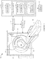
- FIGURE 1 schematically illustrates an imaging system 100 such as a CT scanner.
- the imaging system 100 includes a generally stationary gantry 102 and a rotating gantry 104, which is rotatably supported by the stationary gantry 102 and rotates around an examination region 106 about a z-axis.
- a subject support 108 such as a couch, supports an object or subject in the examination region 106.
- a radiation source 110 such as an x-ray tube, is rotatably supported by the rotating gantry 104, rotates with the rotating gantry 104, and emits radiation that traverses the examination region 106.
- a radiation sensitive detector array 112 subtends an angular arc opposite the radiation source 110 across the examination region 106. The radiation sensitive detector array 112 detects radiation traversing the examination region 106 and generates a signal indicative thereof for each detected photon.
- a reconstructor 114 reconstructs the projection data, generating volumetric image data indicative of a scanned portion of a subject or object located in the examination region 106.
- a general-purpose computing system or computer serves as an operator console 116.
- the console 116 includes a human readable output device such as a monitor and an input device such as a keyboard, mouse, etc.
- Software resident on the console 116 allows the operator to interact with and/or operate the scanner 100 via a graphical user interface (GUI) or otherwise.
- GUI graphical user interface
- a segmentor 118 is configured to facilitate segmenting a vascular tree from the volumetric image data. In one instance, this includes segmenting the coronary tree, identifying center lines of the vessels of the segmented coronary tree, labeling main vessels such as the left coronary artery (LCA), the right coronary artery (RCA), the left anterior descending artery (LDA), etc., and/or labeling a location(s) of interest such as a location of a stenosis.
- LCA left coronary artery
- RCA right coronary artery
- LDA left anterior descending artery
- a location(s) of interest such as a location of a stenosis.
- Manual, semi-automatic and/or automatic segmentation approaches can be utilized. Examples of segmentations are described in Bülow et al., "A General Framework for Tree Segmentation and Reconstruction from Medical Volume Data," MICCAI 2004, Vol.
- a segmentation standardizer 120 is configured to standardize the segmented vascular tree. As described in greater detail below, in one non-limiting instance this includes applying a set of predetermined rules, which selectively prunes or modifies one or more vessels of the vascular tree, including taking into consideration locations of interest, to a "standardized" configuration or tree. As such, a shape, a size and/or geometry of the vascular tree used to determine an FFR (the standardized vascular tree) depends only little, if any, on image resolution, contrast uptake, and/or the operator's segmentation, unlike the original segmentation. Subsequent FFR-CT simulations will be reliable with faithful boundary conditions and accurate predictions.
- a biophysical simulator 122 is configured to at least process the standardized segmented vascular tree to perform a biophysical simulation. With respect toFFR, the biophysical simulator determines an FFR index therefor. As described in greater detail below, in a variation, the simulation is extended to the pruned regions using results of the simulation with the standardized segmented vascular tree for determining initial conditions for the pruned portions. As such, the approach described herein enforces boundary conditions in simulations not just at the inlets and outlets but at locations inside the vessels of the vascular tree. As a result, standardized patient-specific biophysical simulations can be performed where the standardization is achieved through shifting the boundary conditions and extending the simulation beyond.
- FFR approaches are described in patent application serial number US 14/396,407 , publication US 2015/0092999 A1, filed May 10, 2013 , and entitled “Determination of a fractional flow reserve (ffr) value for a stenosis of a vessel," patent application serial number US 14/437,990 , publication US 2015/0282765 A1, filed October 24, 2013 , and entitled “Fractional flow reserve (ffr) index,” and patent application serial number US 14/059,517 , publication US 2015/0112191 A1, filed October 22, 2013 , and entitled "Fractional flow reserve (ffr) index with adaptive boundary condition parameters".
- the FFR index can be displayed via a display monitor 132, stored, conveyed to another device, etc.
- the segmentor 118, the segmentation standardizer 120 and/or the biophysical simulator 122 is implemented with one or more computer processors 124 (e.g., a central processing unit or CPU, a microprocessor, etc.), of a computing system 126, that execute one or more computer readable instructions 128 stored in one or more computer readable storage mediums 130 (which excludes transitory medium) such as physical memory and/or other non-transitory storage medium.
- the processor(s) 124 may additionally or alternatively execute one or more computer readable instructions carried by a carrier wave, a signal and/or other transitory medium.
- the instructions 128 are executed onsite, as shown. In another instance, one or more of the instructions 128 is computed remote from the systems 126, e.g., via a "cloud" and/or other computing resource or service.
- FIGURE 2 schematically illustrates an example of the segmentation standardizer 120.
- the illustrated example of the segmentation standardizer 120 includes a vessel pruner 202 configured to prune the segmented vascular tree using a predetermined set of pruning rules 204.
- the predetermined set of pruning rules 204 includes N rules, where N is a positive integer.
- the predetermined set of pruning rules 204 is a default set of rules.
- the predetermined set of pruning rules 204 includes at least one user and/or facility defined rule.
- the predetermined set of pruning rules 204 includes a combination of default and user and/or facility defined rules.
- the illustrated predetermined set of pruning rules 204 includes a main vessel pruning rule 206, a short vessel pruning rule 208, a location of interest (LOI) pruning rule 210, a distal segment pruning rule 212, a vessel diameter pruning rule 214 and/or one or more other pruning rule 216.
- the one or more other pruning rule 216 is omitted, and the predetermined set of pruning rules 204 includes only the rules 206-214.
- one or more of the rules 206-214 is omitted.
- Another pruning rule can be based on a patient specific parameter, which can be specific to the resolution of the image data, patient anatomy, and/or demographics such as male or female, adult or child, etc.
- An example of the main vessel pruning rule 206 is a main vessel (e.g., RCA, LCA, LAD, etc.) is pruned only if its length, e.g., from the ostium of the aorta along the centerline, is greater than a predetermined length. If a main vessel length is equal to or less than the predetermined length, the main vessel is not pruned. If a main vessel length is greater than the predetermined length, the main vessel is pruned, but only to the predetermined length.
- the predetermined length is a single value in a range of eight centimeters (8 cm) to twelve centimeters (12 cm). In another instance, the predetermined length is a single value in a range of nine centimeters (9 cm) to eleven centimeters (11 cm). In another instance, the predetermined length is ten centimeters (10 cm).
- An example of the short vessel pruning rule 210 is a vessel is pruned off if it has a length that is less than a predetermined length along the centerline. Hence, if a vessel has a length that is less than the predetermined length, the vessel is removed from the vascular tree. If the vessel has a length that is equal to or greater than a predetermined length, the vessel is not pruned.
- the predetermined length is in a range of a quarter to two centimeters (0.25-2.0 cm). In another instance, the predetermined length is in a range of a half to one and a half centimeters (0.5-1.5 cm). In another instance, the predetermined length is one centimeter (1 cm).
- An example of the location of interest pruning rule 210 is an end of a vessel is pruned only if its length from an identified location of interest, which can be identified via a mouse click on a displayed portion of a vessel and/or otherwise, it is greater than a predetermined length. If the length is equal to or less than the predetermined length from the location of interest the end is not pruned. If the length is greater than the predetermined length the end is pruned but only to the predetermined length.
- the predetermined length is in a range of a half to three centimeters (0.5-3.0 cm). In another instance, the predetermined length is in a range of one to two and a half centimeters (1.0-2.5 cm). In another instance, the predetermined length is two centimeters (2.0 cm).
- An example of the distal segment pruning rule 212 is a most distal segment, which is a segment behind a most distal branch, is pruned if its length is greater than a predetermined length from a bifurcation. If the length of the most distal segment is equal to or less than the predetermined length, the most distal segment is not pruned. If the length of the most distal segment is greater than the predetermined length, the most distal segment is pruned but only to the predetermined length.
- the predetermined length is in a range of a half to three centimeters (0.5-3.0 cm). In another instance, the predetermined length is in a range of one to two and a half centimeters (1.0-2.5 cm). In another instance, the predetermined length is two centimeters (2.0 cm).
- the example distal segment pruning rule 212 is constrained by the main vessel pruning rule 206 and the location of interest pruning rule 210.
- the distal segment pruning rule 212 is applied only if the result satisfies the main vessel pruning rule 206 and the location of interest pruning rule 210. If the result of the distal segment pruning rule 212 would not satisfy the main vessel pruning rule 206 and the location of interest pruning rule 210, the distal segment pruning rule 212 is not applied.
- is applying the distal segment pruning rule 212 would result in a main vessel less than 10 cm or a distal end from a location of interest less than 2 cm, the rule 212 is not applied.
- An example of the vessel diameter pruning rule 212 is a vessel is pruned from an outlet (the vessel end) towards an inlet (the region where it is connected to another vessel or the aorta) if a diameter of the vessel is greater than a predetermined vessel diameter. If a vessel diameter is equal or less than the predetermined diameter, the vessel is not pruned. If the vessel diameter is greater than the predetermined diameter, the vessel is pruned but only until the vessel diameter is equal to or less than the predetermined diameter.
- the predetermined diameter is in a range of a half to two and a half millimeters (0.5-2.5 mm). In another instance, the predetermined diameter is in a range of one to two millimeters (1.0-2.0 mm). In another instance, the predetermined diameter is one and a half millimeters (1.5 mm).
- the standardized vascular tree which is the tree used to compute the FFR index, has 1) vessel segments have a standardized length after the last branching location;
- the standardizsed vessel tree can fulfil one or more of: 2) the distal part of the vessels with too small diameter that is not well-defined under a fixed image resolution have little relevance; 3) vessel stumps i.e. very short vessels have unreliable size/volume are ignored; 4) major vessels such as LAD, LCA and RCA have a minimum length; and 5) possible locations of interest to a human operator such as stenoses and/or locations of the vascular tree.
- the rules do not alter the centerline or the lumen segmentation; they merely define the support of the simulation, the location where the boundary conditions are applied, and the anatomical parameters of the boundary condition model.
- Standardization parameters can be fixed for all population and chosen from some range by an optimization process over entire training population.
- the standardization parameters can be personalized from the range for each patient by using patient properties including but not limited to demographic and/or anatomical patient properties such as patient sex, weight, age, heart size.
- the pruning rules 206 optimize FFR-CT predictions of a lumped model pipeline such that they are as accurate as possible.
- the pruning rules 206 optimize the FFR-CT predictions of a lumped model pipeline of Nickisch et al., "Learning Patient-Specific Lumped Models for Interactive Coronary Blood Flow Simulations," MICCAI 2015, pp. 433-441 .
- the pruning rules 206 may also optimize other FFR-CT predictions of a lumped model pipeline.
- the pruning rules 204 decrease user dependence of the simulation and increase the accuracy of lumped model pipeline.
- Other simulations, including other FFR-CT, not using a lumped model are also contemplated herein. For example, simulations based on a mesh such as Finite Elements, Finite Volume, Finite Differences, as well as mesh-free approaches such as particle methods or lattice Boltzman, and/or other approaches are contemplated herein.
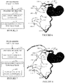
- FIGURE 3 shows a segmented coronary tree, e.g., output by the segmentor 118.
- FIGURE 4 shows a standardized segmented coronary tree, after the segmentation standardizer 120 applies the pruning rules 204 to the segmented coronary tree of FIGURE 3 .
- the rules resulted in pruning ends of vessels 302, 304 306, 308, 310, 312, 314, 316, and 318.
- FIGURE 4 shows pruning markers 402, 404 406, 408, 410, 412, 414, 416, and 418 located at points along the vessels 302, 304 306, 308, 310, 312, 314, 316, and 318 at which ends were pruned.
- the pruned portions could be grayed out and/or otherwise marked.
- FIGURE 5 schematically illustrates an example in which the biophysical simulator 122 is an FFR index determiner.
- the FFR index determiner 122 receives the standardized vascular tree (e.g., FIGURE 4 ) as an input.
- the FFR index determiner 122 includes a boundary condition estimator 502, which is configured to estimate one or more boundary conditions for the standardized vascular tree.
- the boundary condition estimator 502 may determine and/or receive an inlet flow-rate Q o (i.e., a flow rate at the ostium), which can be generated based on data such as subject weight, body mass index (BMI), gender, age, blood test results, anatomical imaging data (e.g., myocardium mass and estimated stroke-volume), and/or subject data, and a geometry of the standardized vascular tree (e.g., a diameter at the ostium D o ). From this, the boundary condition estimator 502 estimates at least one boundary condition such as flow rate Q, average velocity, and/or resistance, at the vessel outlets.
- Q o inlet flow-rate
- BMI body mass index
- anatomical imaging data e.g., myocardium mass and estimated stroke-volume
- subject data e.g., a geometry of the standardized
- the FFR index determiner 122 further includes a standardized vascular tree processor 504, which performs a computational fluid dynamic (CFD) simulation on the standardized vascular tree using the boundary conditions and determines an FFR based on the CFD results.
- the output of the CFD includes volumetric information of pressure and velocity, and the FFR is computed based thereon.
- Another suitable approach is described in Nickisch et al., "Learning Patient-Specific Lumped Models for Interactive Coronary Blood Flow Simulations," MICCAI 2015, Part II, LNCS 9350, pp. 433-441, 2015 .
- FIGURE 6 shows an example displayed output showing the standardized vascular tree ( FIGURE 5 ) with the simulation results (e.g., in gray scale) superimposed or overlaid over the vessels 302, 304 306, 308, 310, 312, 314, 316, and 318.
- the pruning markers 402, 404 406, 408, 410, 412, 414, 416, and 418 are shown to show the point at which the vessels 302, 304 306, 308, 310, 312, 314, 316, and 318 were pruned. This allows the user to see where any pruning was performed.
- the pruning markers are not displayed.
- there are no simulation results for the pruned off portions of the vessels i.e. portions distal to pruning makers 402-418), which are not displayed.
- FIGURE 7 is substantially similar to FIGURE 5 except that the FFR index determiner 122 further includes a pruned vascular segment processor 602.
- the pruned vascular segment processor 602 is configured to determine an FFR value for pruned portions of the vessels using boundary conditions based on the output of the standardized vascular tree processor 504.
- the pruned vascular segment processor 602 extends flow simulations beyond the initial simulation domain of the standardized vascular tree (e.g., FIGURE 4 ).
- the pruned vascular segment processor 602 utilizes a lumped parameter model, as s described below.
- other approaches such as mesh, mesh-free, etc. are also contemplated herein.
- FIGURE 9 An example of a suitable lumped parameter model is shown in FIGURE 9 .
- This example includes n elements and m nodes including ground, where n and m are positive integers.
- a lumped model is set up with nonlinear resistances.
- the black boxes indicate inflow and outflow boundary conditions.
- the white tubes representing tree segment transfer functions ⁇ ( f ) are composed of a series of linear and nonlinear resistance elements reflecting both the local vessel geometry and hydraulic effects. From this, the pruned vascular segment processor 602 considers the pruned portions of the vessels as sequences of non-linear hydraulic resistance elements.
- a volumetric flow rate and an absolute pressure of the pruned simulation at the pruning location are retrieved or read. These values are used as initial values for a subsequent simulation comprising just the pruned part distal the pruning location. For a vessel without branching points, the flow is constant across the vessel. The simulation is an evaluation of the local transfer functions along the pruned vessel.
- an entire hydraulic network (with corresponding inlet conditions) is simulated.
- this includes solving a system of nonlinear equations to obtain the respective flows and pressures.
- A represents a node-to-element matrix
- the subscripts R, P, F and V respectfully indicate resistor, pressure source, flow source and varistor
- R is a diagonal resistance matrix
- f ⁇ F and P ⁇ P are vectors containing pressure/flow source parameters
- ⁇ -1 is an inverse varistor transfer functions stacked into a vector
- q contains absolute pressures relative to a ground node
- f P represents the volumetric flow rate at pressure sources.
- a suitable set of outlet boundary conditions include resistances or outlet flows using a population scaling law.
- FIGURE 8 shows an example displayed output showing the standardized vascular tree ( FIGURE 6 ) with the pruned portions and simulation results, therefore (in gray scale) are superimposed or overlaid over the vessels 302, 304 306, 308, 310, 312, 314, 316, and 318.
- the pruning markers 402, 404 406, 408, 410, 412, 414, 416, and 418 are again shown to show the point at which the vessels 302, 304 306, 308, 310, 312, 314, 316, and 318 were pruned.
- the pruning markers are not displayed.
- the approach described herein allows for performing standardized patient-specific biophysical simulations where the standardization is not constrained to the hard pruning of the segmentation standardizer 120. For example, the result of the computation on the reduced domain is used as a starting point, and then the results for the separate parts of the entire domain are subsequently added without modifying the results on the reduced domain.
- FIGURE 10 illustrates an example method. It is to be appreciated that the ordering of the above acts is not limiting. As such, other orderings are contemplated herein. In addition, one or more acts may be omitted and/or one or more additional acts may be included.
- vascular tree is segmented from the volumetric image data (e.g., CT).
- volumetric image data e.g., CT
- the segmented vascular tree is standardized, as described herein and/or otherwise.
- the segmented vascular tree can be standardized based on a predetermined set of pruning rules, such as those described in connection with FIGURE 2 , which prune off certain portions of certain vessels of the segmented vascular tree.
- a biophysical simulation is performed for the standardized segmented vascular tree.
- the results are visually displayed via a display monitor.
- FIGURE 11 illustrates another example method. It is to be appreciated that the ordering of the above acts is not limiting. As such, other orderings are contemplated herein. In addition, one or more acts may be omitted and/or one or more additional acts may be included.
- vascular tree is segmented from the volumetric image data (e.g., CT).
- volumetric image data e.g., CT
- the segmented vascular tree is standardized, as described herein and/or otherwise.
- the segmented vascular tree can be standardized based on a predetermined set of pruning rules, such as those described in connection with FIGURE 2 , which prune off certain portions of certain vessels of the segmented vascular tree.
- a biophysical simulation is performed for the standardized segmented vascular tree.
- a biophysical simulation is performed for the pruned portions, as described herein and/or otherwise.
- the results are visually displayed via a display monitor.
- the above may be implemented by way of computer readable instructions, encoded or embedded on computer readable storage medium, which, when executed by a computer processor(s), cause the processor(s) to carry out the described acts. Additionally or alternatively, at least one of the computer readable instructions is carried by a signal, carrier wave or other transitory medium, which is not computer readable storage medium.
Landscapes
- Engineering & Computer Science (AREA)
- Health & Medical Sciences (AREA)
- Life Sciences & Earth Sciences (AREA)
- Medical Informatics (AREA)
- Physics & Mathematics (AREA)
- General Health & Medical Sciences (AREA)
- Public Health (AREA)
- Nuclear Medicine, Radiotherapy & Molecular Imaging (AREA)
- Radiology & Medical Imaging (AREA)
- Biomedical Technology (AREA)
- Computer Vision & Pattern Recognition (AREA)
- Theoretical Computer Science (AREA)
- Pathology (AREA)
- Veterinary Medicine (AREA)
- Optics & Photonics (AREA)
- Biophysics (AREA)
- Animal Behavior & Ethology (AREA)
- High Energy & Nuclear Physics (AREA)
- Heart & Thoracic Surgery (AREA)
- Molecular Biology (AREA)
- Surgery (AREA)
- General Physics & Mathematics (AREA)
- Primary Health Care (AREA)
- Epidemiology (AREA)
- Pulmonology (AREA)
- Oral & Maxillofacial Surgery (AREA)
- Physiology (AREA)
- Dentistry (AREA)
- Quality & Reliability (AREA)
- Business, Economics & Management (AREA)
- General Business, Economics & Management (AREA)
- Data Mining & Analysis (AREA)
- Databases & Information Systems (AREA)
- Apparatus For Radiation Diagnosis (AREA)
- Image Processing (AREA)
Description
- The following generally relates to biophysical simulation such as Fractional Flow Reserve (FFR), instantaneous wave-free ratio (iFR), flow simulations and/or other biophysical simulation and more particularly to a vascular tree standardization for biophysical simulation and/or an extension to the biophysical simulation for portions of vessels pruned off the vascular tree during the standardization, and is described with particular application to Fractional Flow Reserve-computed tomography (FFR-CT). However, the following is also amenable to other imaging modalities including X-ray, magnetic resonance imaging (MRI), and/or other imaging modalities, and/or other biophysical simulations.
- Coronary artery disease is among the single largest cause of death worldwide. Fractional Flow Reserve (FFR) is an established invasive measure in the catheterization laboratory (Cath Lab) to quantify, via an FFR index, the hemodynamic significance of a coronary lesion due to calcified or soft plaque. The index indicates the functional severity of a coronary stenosis that is calculated from pressure measurements made during coronary arteriography and is defined as the distal blood pressure (behind a stenosis) relative to the proximal pressure (close to the ostium) under hyperemic conditions. That is, the FFR index expresses the maximal flow down a vessel in the presence of a stenosis compared to the maximal flow in the hypothetical absence of the stenosis. The FFR value is an absolute number between 0 and 1, where a value 0.50 indicates that a given stenosis causes a 50% drop in blood pressure.
-
WO 2014/072861 discloses a classification of an unknown FFR based on certain extracted features. -
WO 2011/093921 discloses a system, which automatically identifies one or more vascular regions in a medical image. - NICKISCH HANNES ET AL disclose in "Learning Patient-Specific Lumped Models for Interactive Coronary Blood Flow Simulations", 20 November 2015 finite element simulation for lumped models.
- FFR is an invasive procedure in that it requires insertion of a catheter into the femoral or radial arteries and advancement of the catheter to the stenosis where a sensor at the tip of the catheter senses pressure, temperature, and flow across the stenosis, during conditions promoted by various agents that effect vessel geometry, compliance and resistance, and/or other characteristics. FFR-CT is a non-invasive simulation-based surrogate for invasive FFR based on a standard cardiac CT angiogram (CCTA). This approach estimates the FFR index is through computational fluid dynamic (CFD) simulations in which blood flow and pressure through the coronaries is simulated. One simulation approach, unfortunately, requires the CCTA be sent to an off-site central data center for processing, including cardiac segmentation, coronary segmentation and FFR simulation, which can delay results.
- The length of automatically segmented coronary arteries in a conventional CTA scan depends on the effective image resolution and a good contrast agent uptake in the coronaries. Furthermore, in semi-automatic segmentation with a human operator guiding the coronary tree extraction, the ability and effort of the human operator are also strongly contributing to the number and length of the extracted vessels. Boundary conditions of patient-specific biophysical models used in FFR-CT predictions are supposed to simulate the effect of the microvasculature which is typically invisible in the image. They are usually applied at the distal ends of the coronary segmentation. Population averages and/or scaling laws are used to shape the boundary conditions; hence they depend on the local size and width of the vessel and, as a consequence, also on the operator, the image resolution etc. Unfortunately, this can hamper the reproducibility and reliability of FFR-CT simulations.
- The invention is defined in the claims.
- Aspects described herein address the above-referenced problems and others.
- In one aspect, a computing system includes a computer readable storage medium with computer executable instructions including: a segmentation standardizer configured to determine a standardized vascular tree from a segmented vascular tree segmented of volumetric image data and a predetermined set of pruning rules, and a biophysical simulator configured to perform a biophysical simulation based on the standardized vascular tree. The computing system further includes a processor configured to execute the segmentation standardizer to determine the standardized vascular tree from the segmented vascular tree segmented of volumetric image data and the predetermined set of pruning rules, and configured to execute the biophysical simulator to perform a biophysical simulation based on the standardized vascular tree. The computing system further includes a display configured to display at least one of the standardized vascular tree and a result of the biophysical simulation.
- In another aspect, a computer readable storage medium is encoded with computer readable instructions, which, when executed by a computer processor of a computing system, causes the computer processor to: execute a segmentation standardizer configured to determine a standardized vascular tree from a segmented vascular tree segmented of volumetric image data using a predetermined set of pruning rules, execute a biophysical simulator configured to perform a biophysical simulation based on the standardized vascular tree, and display via a display monitor configured to display at least one of the standardized vascular tree and a result of the biophysical simulation.
- In another aspect, a method includes standardizing a segmented vascular tree using a predetermined set of pruning rules, thereby creating a standardized vascular tree. The method further includes performing a biophysical simulation for the standardized vascular tree. The method further includes displaying a result of the biophysical simulation.
- Those skilled in the art will recognize still other aspects of the present application upon reading and understanding the attached description.
- The drawings are only for purposes of illustrating the preferred embodiments and are not to be construed as limiting the invention.
-
FIGURE 1 schematically illustrates a computing system, which is configured at least to standardize a segmented vascular tree by selectively pruning off portions thereof and determine an FFR index for the standardized vascular tree and, optionally, selectively pruned off portions. -
FIGURE 2 schematically illustrates an example of a segmentation standardizer used to standardize the segmented vascular tree. -
FIGURE 3 shows an example of a segmented vascular tree before pruning by the segmentation standardizer. -
FIGURE 4 shows an example of the segmented vascular tree ofFIGURE 3 after pruning by the segmentation standardizer using the pruning rules described herein. -
FIGURE 5 schematically illustrates an example of a FFR index determiner that computes an FFR index for the standardized vascular tree. -
FIGURE 6 shows the standardized vascular tree with the FFR index superimposed there over. -
FIGURE 7 schematically illustrates an example of a FFR index determiner that computes an FFR index for the standardized vascular tree and the pruned portions. -
FIGURE 8 shows the segmented vascular tree with the FFR index for the standardized vascular tree and the pruned portions superimposed there over. -
FIGURE 9 schematically illustrates a lumped parameter model for modelling the pruned portions. -
FIGURE 10 illustrates an example method for determining a standardized vascular tree and an FFR index therefore. -
FIGURE 11 illustrates an example method for determining a standardized vascular tree and an FFR index therefore and for portions thereof pruned off. - The following generally relates to vascular tree standardization for a biophysical simulation and/or an extension to the biophysical simulation for portions of vessels pruned off the vascular tree during the standardization. For sake of brevity and explanatory purposes, the following is described with particular application to a non-limiting example of FFR-CT. However, it is to be understood the standardized vascular tree can be used with an application that uses a vacular or other tree structure.
-
FIGURE 1 schematically illustrates animaging system 100 such as a CT scanner. Theimaging system 100 includes a generallystationary gantry 102 and a rotatinggantry 104, which is rotatably supported by thestationary gantry 102 and rotates around anexamination region 106 about a z-axis. Asubject support 108, such as a couch, supports an object or subject in theexamination region 106. - A
radiation source 110, such as an x-ray tube, is rotatably supported by the rotatinggantry 104, rotates with the rotatinggantry 104, and emits radiation that traverses theexamination region 106. A radiationsensitive detector array 112 subtends an angular arc opposite theradiation source 110 across theexamination region 106. The radiationsensitive detector array 112 detects radiation traversing theexamination region 106 and generates a signal indicative thereof for each detected photon. - A
reconstructor 114 reconstructs the projection data, generating volumetric image data indicative of a scanned portion of a subject or object located in theexamination region 106. A general-purpose computing system or computer serves as anoperator console 116. Theconsole 116 includes a human readable output device such as a monitor and an input device such as a keyboard, mouse, etc. Software resident on theconsole 116 allows the operator to interact with and/or operate thescanner 100 via a graphical user interface (GUI) or otherwise. - A
segmentor 118 is configured to facilitate segmenting a vascular tree from the volumetric image data. In one instance, this includes segmenting the coronary tree, identifying center lines of the vessels of the segmented coronary tree, labeling main vessels such as the left coronary artery (LCA), the right coronary artery (RCA), the left anterior descending artery (LDA), etc., and/or labeling a location(s) of interest such as a location of a stenosis. Manual, semi-automatic and/or automatic segmentation approaches can be utilized. Examples of segmentations are described in Bülow et al., "A General Framework for Tree Segmentation and Reconstruction from Medical Volume Data," MICCAI 2004, Vol. 3216, Lecture Notes in Computer Science, pp 533-540, and Gülsün et al., "Coronary Centerline Extraction via Optimal Flow Paths and CNN Path Pruning," MICCAI 2016, Vol. 9902, Lecture Notes in Computer Science, pp 317-325. - A
segmentation standardizer 120 is configured to standardize the segmented vascular tree. As described in greater detail below, in one non-limiting instance this includes applying a set of predetermined rules, which selectively prunes or modifies one or more vessels of the vascular tree, including taking into consideration locations of interest, to a "standardized" configuration or tree. As such, a shape, a size and/or geometry of the vascular tree used to determine an FFR (the standardized vascular tree) depends only little, if any, on image resolution, contrast uptake, and/or the operator's segmentation, unlike the original segmentation. Subsequent FFR-CT simulations will be reliable with faithful boundary conditions and accurate predictions. - A
biophysical simulator 122 is configured to at least process the standardized segmented vascular tree to perform a biophysical simulation. With respect toFFR, the biophysical simulator determines an FFR index therefor. As described in greater detail below, in a variation, the simulation is extended to the pruned regions using results of the simulation with the standardized segmented vascular tree for determining initial conditions for the pruned portions. As such, the approach described herein enforces boundary conditions in simulations not just at the inlets and outlets but at locations inside the vessels of the vascular tree. As a result, standardized patient-specific biophysical simulations can be performed where the standardization is achieved through shifting the boundary conditions and extending the simulation beyond. - Examples of FFR approaches are described in patent application serial number
US 14/396,407 US 2015/0092999 A1, filed May 10, 2013 , and entitled "Determination of a fractional flow reserve (ffr) value for a stenosis of a vessel," patent application serial numberUS 14/437,990 US 2015/0282765 A1, filed October 24, 2013 , and entitled "Fractional flow reserve (ffr) index," and patent application serial numberUS 14/059,517 US 2015/0112191 A1, filed October 22, 2013 , and entitled "Fractional flow reserve (ffr) index with adaptive boundary condition parameters". The FFR index can be displayed via adisplay monitor 132, stored, conveyed to another device, etc. - In the illustrated example, the
segmentor 118, thesegmentation standardizer 120 and/or thebiophysical simulator 122 is implemented with one or more computer processors 124 (e.g., a central processing unit or CPU, a microprocessor, etc.), of acomputing system 126, that execute one or more computerreadable instructions 128 stored in one or more computer readable storage mediums 130 (which excludes transitory medium) such as physical memory and/or other non-transitory storage medium. The processor(s) 124 may additionally or alternatively execute one or more computer readable instructions carried by a carrier wave, a signal and/or other transitory medium. Theinstructions 128 are executed onsite, as shown. In another instance, one or more of theinstructions 128 is computed remote from thesystems 126, e.g., via a "cloud" and/or other computing resource or service. -
FIGURE 2 schematically illustrates an example of thesegmentation standardizer 120. - The illustrated example of the
segmentation standardizer 120 includes avessel pruner 202 configured to prune the segmented vascular tree using a predetermined set of pruning rules 204. The predetermined set ofpruning rules 204 includes N rules, where N is a positive integer. In one instance, the predetermined set ofpruning rules 204 is a default set of rules. In another instance, the predetermined set ofpruning rules 204 includes at least one user and/or facility defined rule. In another instance, the predetermined set ofpruning rules 204 includes a combination of default and user and/or facility defined rules. - The illustrated predetermined set of
pruning rules 204 includes a mainvessel pruning rule 206, a shortvessel pruning rule 208, a location of interest (LOI)pruning rule 210, a distalsegment pruning rule 212, a vesseldiameter pruning rule 214 and/or one or moreother pruning rule 216. In a variation, the one or moreother pruning rule 216 is omitted, and the predetermined set ofpruning rules 204 includes only the rules 206-214. In another embodiment, one or more of the rules 206-214 is omitted. Another pruning rule can be based on a patient specific parameter, which can be specific to the resolution of the image data, patient anatomy, and/or demographics such as male or female, adult or child, etc. - An example of the main
vessel pruning rule 206 is a main vessel (e.g., RCA, LCA, LAD, etc.) is pruned only if its length, e.g., from the ostium of the aorta along the centerline, is greater than a predetermined length. If a main vessel length is equal to or less than the predetermined length, the main vessel is not pruned. If a main vessel length is greater than the predetermined length, the main vessel is pruned, but only to the predetermined length. In one instance, the predetermined length is a single value in a range of eight centimeters (8 cm) to twelve centimeters (12 cm). In another instance, the predetermined length is a single value in a range of nine centimeters (9 cm) to eleven centimeters (11 cm). In another instance, the predetermined length is ten centimeters (10 cm). - An example of the short
vessel pruning rule 210 is a vessel is pruned off if it has a length that is less than a predetermined length along the centerline. Hence, if a vessel has a length that is less than the predetermined length, the vessel is removed from the vascular tree. If the vessel has a length that is equal to or greater than a predetermined length, the vessel is not pruned. In one instance, the predetermined length is in a range of a quarter to two centimeters (0.25-2.0 cm). In another instance, the predetermined length is in a range of a half to one and a half centimeters (0.5-1.5 cm). In another instance, the predetermined length is one centimeter (1 cm). - An example of the location of
interest pruning rule 210 is an end of a vessel is pruned only if its length from an identified location of interest, which can be identified via a mouse click on a displayed portion of a vessel and/or otherwise, it is greater than a predetermined length. If the length is equal to or less than the predetermined length from the location of interest the end is not pruned. If the length is greater than the predetermined length the end is pruned but only to the predetermined length. In one instance, the predetermined length is in a range of a half to three centimeters (0.5-3.0 cm). In another instance, the predetermined length is in a range of one to two and a half centimeters (1.0-2.5 cm). In another instance, the predetermined length is two centimeters (2.0 cm). - An example of the distal
segment pruning rule 212 is a most distal segment, which is a segment behind a most distal branch, is pruned if its length is greater than a predetermined length from a bifurcation. If the length of the most distal segment is equal to or less than the predetermined length, the most distal segment is not pruned. If the length of the most distal segment is greater than the predetermined length, the most distal segment is pruned but only to the predetermined length. In one instance, the predetermined length is in a range of a half to three centimeters (0.5-3.0 cm). In another instance, the predetermined length is in a range of one to two and a half centimeters (1.0-2.5 cm). In another instance, the predetermined length is two centimeters (2.0 cm). - In one instance, the example distal
segment pruning rule 212 is constrained by the mainvessel pruning rule 206 and the location ofinterest pruning rule 210. For example, the distalsegment pruning rule 212 is applied only if the result satisfies the mainvessel pruning rule 206 and the location ofinterest pruning rule 210. If the result of the distalsegment pruning rule 212 would not satisfy the mainvessel pruning rule 206 and the location ofinterest pruning rule 210, the distalsegment pruning rule 212 is not applied. For example, is applying the distalsegment pruning rule 212 would result in a main vessel less than 10 cm or a distal end from a location of interest less than 2 cm, therule 212 is not applied. - An example of the vessel
diameter pruning rule 212 is a vessel is pruned from an outlet (the vessel end) towards an inlet (the region where it is connected to another vessel or the aorta) if a diameter of the vessel is greater than a predetermined vessel diameter. If a vessel diameter is equal or less than the predetermined diameter, the vessel is not pruned. If the vessel diameter is greater than the predetermined diameter, the vessel is pruned but only until the vessel diameter is equal to or less than the predetermined diameter. In one instance, the predetermined diameter is in a range of a half to two and a half millimeters (0.5-2.5 mm). In another instance, the predetermined diameter is in a range of one to two millimeters (1.0-2.0 mm). In another instance, the predetermined diameter is one and a half millimeters (1.5 mm). - By applying the pruning rules described herein, the standardized vascular tree, which is the tree used to compute the FFR index, has 1) vessel segments have a standardized length after the last branching location; The standardizsed vessel tree can fulfil one or more of: 2) the distal part of the vessels with too small diameter that is not well-defined under a fixed image resolution have little relevance; 3) vessel stumps i.e. very short vessels have unreliable size/volume are ignored; 4) major vessels such as LAD, LCA and RCA have a minimum length; and 5) possible locations of interest to a human operator such as stenoses and/or locations of the vascular tree. The rules do not alter the centerline or the lumen segmentation; they merely define the support of the simulation, the location where the boundary conditions are applied, and the anatomical parameters of the boundary condition model.
- Standardization parameters can be fixed for all population and chosen from some range by an optimization process over entire training population. Alternatively, the standardization parameters can be personalized from the range for each patient by using patient properties including but not limited to demographic and/or anatomical patient properties such as patient sex, weight, age, heart size.
- With one FFR-CT approach, the pruning rules 206 optimize FFR-CT predictions of a lumped model pipeline such that they are as accurate as possible. For example, the pruning rules 206 optimize the FFR-CT predictions of a lumped model pipeline of Nickisch et al., "Learning Patient-Specific Lumped Models for Interactive Coronary Blood Flow Simulations," MICCAI 2015, pp. 433-441. The pruning rules 206 may also optimize other FFR-CT predictions of a lumped model pipeline. Empirically, the pruning rules 204 decrease user dependence of the simulation and increase the accuracy of lumped model pipeline. Other simulations, including other FFR-CT, not using a lumped model are also contemplated herein. For example, simulations based on a mesh such as Finite Elements, Finite Volume, Finite Differences, as well as mesh-free approaches such as particle methods or lattice Boltzman, and/or other approaches are contemplated herein.
-
FIGURE 3 shows a segmented coronary tree, e.g., output by thesegmentor 118.FIGURE 4 shows a standardized segmented coronary tree, after thesegmentation standardizer 120 applies the pruning rules 204 to the segmented coronary tree ofFIGURE 3 . In this example, the rules resulted in pruning ends ofvessels FIGURE 4 showspruning markers 402, 404 406, 408, 410, 412, 414, 416, and 418 located at points along thevessels -
FIGURE 5 schematically illustrates an example in which thebiophysical simulator 122 is an FFR index determiner. TheFFR index determiner 122 receives the standardized vascular tree (e.g.,FIGURE 4 ) as an input. - The
FFR index determiner 122 includes aboundary condition estimator 502, which is configured to estimate one or more boundary conditions for the standardized vascular tree. For example, theboundary condition estimator 502 may determine and/or receive an inlet flow-rate Qo (i.e., a flow rate at the ostium), which can be generated based on data such as subject weight, body mass index (BMI), gender, age, blood test results, anatomical imaging data (e.g., myocardium mass and estimated stroke-volume), and/or subject data, and a geometry of the standardized vascular tree (e.g., a diameter at the ostium Do). From this, theboundary condition estimator 502 estimates at least one boundary condition such as flow rate Q, average velocity, and/or resistance, at the vessel outlets. - By way of non-limiting example, in one instance the
boundary condition estimator 502 estimates a flow rate boundary condition Q at the outlet as a function of Qo and Do as


- The
FFR index determiner 122 further includes a standardizedvascular tree processor 504, which performs a computational fluid dynamic (CFD) simulation on the standardized vascular tree using the boundary conditions and determines an FFR based on the CFD results. The output of the CFD includes volumetric information of pressure and velocity, and the FFR is computed based thereon. For example, the FFR is computed as a ratio of maximum blood flow distal to a stenotic lesion (Pd) to normal maximum flow in the same vessel (Pa), or FFR = Pd/Pa. Another suitable approach is described in Nickisch et al., "Learning Patient-Specific Lumped Models for Interactive Coronary Blood Flow Simulations," MICCAI 2015, Part II, LNCS 9350, pp. 433-441, 2015. -
FIGURE 6 shows an example displayed output showing the standardized vascular tree (FIGURE 5 ) with the simulation results (e.g., in gray scale) superimposed or overlaid over thevessels pruning markers 402, 404 406, 408, 410, 412, 414, 416, and 418 are shown to show the point at which thevessels FIGURE 6 , there are no simulation results for the pruned off portions of the vessels (i.e. portions distal to pruning makers 402-418), which are not displayed. -
FIGURE 7 is substantially similar toFIGURE 5 except that theFFR index determiner 122 further includes a prunedvascular segment processor 602. The prunedvascular segment processor 602 is configured to determine an FFR value for pruned portions of the vessels using boundary conditions based on the output of the standardizedvascular tree processor 504. The prunedvascular segment processor 602 extends flow simulations beyond the initial simulation domain of the standardized vascular tree (e.g.,FIGURE 4 ). In one instance, the prunedvascular segment processor 602 utilizes a lumped parameter model, as s described below. However, as described herein, other approaches such as mesh, mesh-free, etc. are also contemplated herein. - An example of a suitable lumped parameter model is shown in
FIGURE 9 . This example includes n elements and m nodes including ground, where n and m are positive integers. Based on the centerline representation, a lumped model is set up with nonlinear resistances. The black boxes indicate inflow and outflow boundary conditions. The white tubes representing tree segment transfer functions φ(f) are composed of a series of linear and nonlinear resistance elements reflecting both the local vessel geometry and hydraulic effects. From this, the prunedvascular segment processor 602 considers the pruned portions of the vessels as sequences of non-linear hydraulic resistance elements. - For a continuation of a pruned vessel, a volumetric flow rate and an absolute pressure of the pruned simulation at the pruning location (the pruning markers 402-418) are retrieved or read. These values are used as initial values for a subsequent simulation comprising just the pruned part distal the pruning location. For a vessel without branching points, the flow is constant across the vessel. The simulation is an evaluation of the local transfer functions along the pruned vessel.
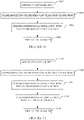
- Where an entire subtree is pruned away, an entire hydraulic network (with corresponding inlet conditions) is simulated. In one instance, this includes solving a system of nonlinear equations to obtain the respective flows and pressures. An example a system of nonlinear equations is:

- Where a subtree or a vessel is entirely removed in the pruning process and the subtree or vessel was branching from another vessel, then there is no flow left and a value of zero is assigned, and, thus, constant pressure and constant FFR values are assigned along the entire subtree. Everything beyond that would require a way of determining which part of the main flow would be going through the subtree or vessel and would finally require a modification of the simulation results on the pruned domain.
-
FIGURE 8 shows an example displayed output showing the standardized vascular tree (FIGURE 6 ) with the pruned portions and simulation results, therefore (in gray scale) are superimposed or overlaid over thevessels pruning markers 402, 404 406, 408, 410, 412, 414, 416, and 418 are again shown to show the point at which thevessels - The approach described herein allows for performing standardized patient-specific biophysical simulations where the standardization is not constrained to the hard pruning of the
segmentation standardizer 120. For example, the result of the computation on the reduced domain is used as a starting point, and then the results for the separate parts of the entire domain are subsequently added without modifying the results on the reduced domain. -
FIGURE 10 illustrates an example method. It is to be appreciated that the ordering of the above acts is not limiting. As such, other orderings are contemplated herein. In addition, one or more acts may be omitted and/or one or more additional acts may be included. - At 1002, a vascular tree is segmented from the volumetric image data (e.g., CT).
- At 1004, the segmented vascular tree is standardized, as described herein and/or otherwise. For example, the segmented vascular tree can be standardized based on a predetermined set of pruning rules, such as those described in connection with
FIGURE 2 , which prune off certain portions of certain vessels of the segmented vascular tree. - At 1006, a biophysical simulation is performed for the standardized segmented vascular tree.
- At 1008, the results (e.g., the standardized segmented vascular tree and FFR index) are visually displayed via a display monitor.
-
FIGURE 11 illustrates another example method. It is to be appreciated that the ordering of the above acts is not limiting. As such, other orderings are contemplated herein. In addition, one or more acts may be omitted and/or one or more additional acts may be included. - At 1102, a vascular tree is segmented from the volumetric image data (e.g., CT).
- At 1104, the segmented vascular tree is standardized, as described herein and/or otherwise. For example, the segmented vascular tree can be standardized based on a predetermined set of pruning rules, such as those described in connection with
FIGURE 2 , which prune off certain portions of certain vessels of the segmented vascular tree. - At 1106, a biophysical simulation is performed for the standardized segmented vascular tree.
- At 1108, a biophysical simulation is performed for the pruned portions, as described herein and/or otherwise.
- At 1008, the results (e.g., the segmented vascular tree and FFR index for the standardized and pruned portions) are visually displayed via a display monitor.
- The above may be implemented by way of computer readable instructions, encoded or embedded on computer readable storage medium, which, when executed by a computer processor(s), cause the processor(s) to carry out the described acts. Additionally or alternatively, at least one of the computer readable instructions is carried by a signal, carrier wave or other transitory medium, which is not computer readable storage medium.
- The embodiments of the invention have been described with reference to the preferred embodiments. Modifications and alterations may occur to others upon reading and understanding the preceding detailed description.
Claims (15)
- A computing system (126), comprising:a computer readable storage medium (130) with computer executable instructions (128), including: a segmentation standardizer (120) configured to determine a standardized vascular tree, with vessel segments that have predetermined lengths after the last branching location, from a segmented vascular tree segmented of volumetric image data and a predetermined set of pruning rules (206), and a biophysical simulator (122) configured to perform a biophysical simulation based on the standardized vascular tree;a processor (124) configured to execute the segmentation standardizer to determine the standardized vascular tree from the segmented vascular tree segmented of volumetric image data and the predetermined set of pruning rules, and configured to execute the biophysical simulator to perform a biophysical simulation based on the standardized vascular tree; anda display configured to display at least one of the standardized vascular tree and a result of the biophysical simulation.
- The computing system of claim 1, wherein the predetermined set of pruning rules includes at least a main vessel pruning rule (206), a short vessel pruning rule (208), a location of interest pruning rule (210), a distal segment pruning rule (212), and a vessel diameter pruning rule (214).
- The computing system of claim 2, wherein the processor, based on the main vessel pruning rule, prunes a main vessel only if a length of the main vessel, from an aorta to an end of the vessel, is greater than a predetermined main vessel length, and only up to the predetermined main vessel length.
- The computing system of claim 3, wherein the processor, based on the short vessel pruning rule, prunes prune off a vessel only if a length of the short vessel is less than a predetermined short vessel length.
- The computing system of claim 4, wherein the processor, based on the location of interest pruning rule, prunes an end of a vessel from a location of interest only if a length of the end from the location of interest is greater than a predetermined location of interest length and only up to the predetermined location of interest length.
- The computing system of claim 5, wherein the processor, based on the distal segment pruning rule, prunes a distal end of a vessel from a branch only if a length of the distal end from the branch is greater than a predetermined distal segment length and only up to the predetermined distal segment length.
- The computing system of claim 6, wherein the distal segment pruning rule is constrained by the main vessel pruning rule and the location of interest pruning rule.
- The computing system of any of claims 6 to 7, wherein the processor, based on the vessel diameter pruning rule, prunes a vessel from an outlet of the vessel towards an inlet of the vessel up only if a vessel diameter of the vessel is greater than a predetermined vessel diameter and only until the predetermined vessel diameter is reached.
- The computing system of any of claims 2 to 8, wherein the biophysical simulator further includes a pruned vascular segment processor (602) configured to perform a biophysical simulation for only pruned portions of the segmented vascular tree.
- The computing system of claim 9, wherein for a pruned portion that is a continuation of a pruned vessel, the processor utilizes a volumetric flow rate and an absolute pressure from the biophysical simulation of the standardized vascular tree as initial values for a simulation for just the pruned portion to determine the biophysical simulation for the pruned portion.
- The computing system of any of claims 9 to 10, wherein for an entire pruned subtree, the processor simulates an entire hydraulic network by solving a system of nonlinear equations to obtain flows and pressures and to determine the biophysical simulation for the pruned subtree.
- The computing system of any of claims 9 to 11, wherein for an entire pruned vessel or subtree pruned from another vessel, the processor determines a constant pressure and assigns constant values along the entire pruned vessel or subtree.
- The computing system of any of claims 9 to 12, wherein the display is configured to display the segmented vascular tree and the simulation results for the standardized vascular tree and the pruned portions.
- A computer readable storage medium encoded with computer readable instructions, which, when executed by a processor of a computing system, causes the processor to:execute a segmentation standardizer configured to determine a standardized vascular tree, with vessel segments that have predetermined lengths after the last branching location, from a segmented vascular tree segmented of volumetric image data using a predetermined set of pruning rules;execute a biophysical simulator configured to perform a biophysical simulation based on the standardized vascular tree; anddisplay via a display monitor configured to display at least one of the standardized vascular tree and a result of the biophysical simulation.
- The computer readable storage medium of claim 14, wherein the predetermined set of pruning rules includes at least a main vessel pruning rule (206), a short vessel pruning rule (208), a location of interest pruning rule (210), a distal segment pruning rule (212), and a vessel diameter pruning rule (214).
Applications Claiming Priority (2)
| Application Number | Priority Date | Filing Date | Title |
|---|---|---|---|
| US201662425181P | 2016-11-22 | 2016-11-22 | |
| PCT/EP2017/079378 WO2018095791A1 (en) | 2016-11-22 | 2017-11-16 | Vascular tree standardization for biophysical simulation and/or an extension simulation for pruned portions |
Publications (2)
| Publication Number | Publication Date |
|---|---|
| EP3544512A1 EP3544512A1 (en) | 2019-10-02 |
| EP3544512B1 true EP3544512B1 (en) | 2022-09-14 |
Family
ID=60582555
Family Applications (1)
| Application Number | Title | Priority Date | Filing Date |
|---|---|---|---|
| EP17809208.6A Active EP3544512B1 (en) | 2016-11-22 | 2017-11-16 | Vascular tree standardization for biophysical simulation and/or an extension simulation for pruned portions |
Country Status (5)
| Country | Link |
|---|---|
| US (1) | US11055845B2 (en) |
| EP (1) | EP3544512B1 (en) |
| JP (1) | JP6975235B2 (en) |
| CN (1) | CN109996495B (en) |
| WO (1) | WO2018095791A1 (en) |
Families Citing this family (8)
| Publication number | Priority date | Publication date | Assignee | Title |
|---|---|---|---|---|
| WO2017199245A1 (en) | 2016-05-16 | 2017-11-23 | Cathworks Ltd. | System for vascular assessment |
| IL263066B2 (en) | 2016-05-16 | 2023-09-01 | Cathworks Ltd | Vascular selection from images |
| CN110494893B (en) | 2017-03-31 | 2024-01-23 | 皇家飞利浦有限公司 | FFR-based interactive monitoring of non-invasive imaging |
| EP3948886A4 (en) | 2019-04-01 | 2022-12-21 | CathWorks Ltd. | Methods and apparatus for angiographic image selection |
| WO2021059165A1 (en) | 2019-09-23 | 2021-04-01 | Cathworks Ltd. | Methods, apparatus, and system for synchronization between a three-dimensional vascular model and an imaging device |
| CN112862759B (en) * | 2021-01-19 | 2023-06-23 | 杭州深睿博联科技有限公司 | Image processing method, device, equipment and computer readable storage medium |
| KR20220111526A (en) * | 2021-02-02 | 2022-08-09 | 자이메드 주식회사 | Apparatus and method for identifying real-time biometric image |
| CN114820554A (en) * | 2022-05-11 | 2022-07-29 | 杭州类脑科技有限公司 | Liver blood vessel extraction method, system and computer readable storage medium based on global automatic growth |
Family Cites Families (15)
| Publication number | Priority date | Publication date | Assignee | Title |
|---|---|---|---|---|
| US7225011B2 (en) | 2001-04-02 | 2007-05-29 | Koninklijke Philips Electronics, N.V. | Heart modeling using a template |
| US8543338B2 (en) | 2007-01-16 | 2013-09-24 | Simbionix Ltd. | System and method for performing computerized simulations for image-guided procedures using a patient specific model |
| WO2011093921A1 (en) * | 2010-01-29 | 2011-08-04 | Mayo Foundation For Medical Education And Research | Automated vascular region separation in medical imaging |
| US8315812B2 (en) | 2010-08-12 | 2012-11-20 | Heartflow, Inc. | Method and system for patient-specific modeling of blood flow |
| EP2749224A4 (en) | 2011-08-26 | 2015-12-02 | Ebm Corp | Bloodstream simulation system for simulating blood vessel treatment effect, method therefor, and computer software program |
| WO2013171644A1 (en) | 2012-05-14 | 2013-11-21 | Koninklijke Philips N.V. | Determination of a fractional flow reserve (ffr) value for a stenosis of a vessel |
| JP6302922B2 (en) * | 2012-11-06 | 2018-03-28 | コーニンクレッカ フィリップス エヌ ヴェKoninklijke Philips N.V. | Coronary flow reserve ratio (FFR) index |
| US9424395B2 (en) | 2013-03-04 | 2016-08-23 | Heartflow, Inc. | Method and system for sensitivity analysis in modeling blood flow characteristics |
| US9788807B2 (en) | 2013-09-06 | 2017-10-17 | Koninklijke Philips N.V. | Processing apparatus for processing cardiac data |
| US10595806B2 (en) | 2013-10-22 | 2020-03-24 | Koninklijke Philips N.V. | Fractional flow reserve (FFR) index with adaptive boundary condition parameters |
| US8977339B1 (en) | 2013-12-05 | 2015-03-10 | Intrinsic Medical Imaging Llc | Method for assessing stenosis severity through stenosis mapping |
| US9087147B1 (en) | 2014-03-31 | 2015-07-21 | Heartflow, Inc. | Systems and methods for determining blood flow characteristics using flow ratio |
| WO2016055899A1 (en) * | 2014-10-10 | 2016-04-14 | Koninklijke Philips N.V. | Tace navigation guidance based on tumor viability and vascular geometry |
| WO2016087396A1 (en) | 2014-12-02 | 2016-06-09 | Koninklijke Philips N.V. | Fractional flow reserve determination |
| WO2017102467A1 (en) * | 2015-12-15 | 2017-06-22 | Koninklijke Philips N.V. | Method of data processing for computed tomography |
-
2017
- 2017-11-16 EP EP17809208.6A patent/EP3544512B1/en active Active
- 2017-11-16 WO PCT/EP2017/079378 patent/WO2018095791A1/en unknown
- 2017-11-16 JP JP2019527317A patent/JP6975235B2/en active Active
- 2017-11-16 US US16/348,282 patent/US11055845B2/en active Active
- 2017-11-16 CN CN201780072241.9A patent/CN109996495B/en active Active
Also Published As
| Publication number | Publication date |
|---|---|
| US11055845B2 (en) | 2021-07-06 |
| WO2018095791A1 (en) | 2018-05-31 |
| JP2020510451A (en) | 2020-04-09 |
| CN109996495A (en) | 2019-07-09 |
| US20190318475A1 (en) | 2019-10-17 |
| CN109996495B (en) | 2023-04-28 |
| JP6975235B2 (en) | 2021-12-01 |
| EP3544512A1 (en) | 2019-10-02 |
Similar Documents
| Publication | Publication Date | Title |
|---|---|---|
| EP3544512B1 (en) | Vascular tree standardization for biophysical simulation and/or an extension simulation for pruned portions | |
| US10595806B2 (en) | Fractional flow reserve (FFR) index with adaptive boundary condition parameters | |
| US9757073B2 (en) | Fractional flow reserve (FFR) index | |
| EP3140757B1 (en) | Method and system for non-invasive functional assessment of coronary artery stenosis using flow computations in models based on diseased patients and hypothetical normal anatomical models | |
| JP6484760B2 (en) | Modeling collateral blood flow for non-invasive blood flow reserve ratio (FFR) | |
| CN106572824A (en) | Stenosis assessment | |
| EP3244790B1 (en) | Instantaneous wave-free ratio (ifr) computer tomography (ct) | |
| JP7300392B2 (en) | Standardized Coronary Artery Disease Metrics | |
| JP7426824B2 (en) | Non-invasive imaging-based FFR interaction monitoring | |
| US20230252628A1 (en) | Estimating flow to vessel bifurcations for simulated hemodynamics | |
| US11664128B2 (en) | Estimating flow to vessel bifurcations for simulated hemodynamics | |
| JPWO2018185040A5 (en) |
Legal Events
| Date | Code | Title | Description |
|---|---|---|---|
| STAA | Information on the status of an ep patent application or granted ep patent |
Free format text: STATUS: UNKNOWN |
|
| STAA | Information on the status of an ep patent application or granted ep patent |
Free format text: STATUS: THE INTERNATIONAL PUBLICATION HAS BEEN MADE |
|
| PUAI | Public reference made under article 153(3) epc to a published international application that has entered the european phase |
Free format text: ORIGINAL CODE: 0009012 |
|
| STAA | Information on the status of an ep patent application or granted ep patent |
Free format text: STATUS: REQUEST FOR EXAMINATION WAS MADE |
|
| 17P | Request for examination filed |
Effective date: 20190624 |
|
| AK | Designated contracting states |
Kind code of ref document: A1 Designated state(s): AL AT BE BG CH CY CZ DE DK EE ES FI FR GB GR HR HU IE IS IT LI LT LU LV MC MK MT NL NO PL PT RO RS SE SI SK SM TR |
|
| AX | Request for extension of the european patent |
Extension state: BA ME |
|
| DAV | Request for validation of the european patent (deleted) | ||
| DAX | Request for extension of the european patent (deleted) | ||
| RAP1 | Party data changed (applicant data changed or rights of an application transferred) |
Owner name: KONINKLIJKE PHILIPS N.V. |
|
| GRAP | Despatch of communication of intention to grant a patent |
Free format text: ORIGINAL CODE: EPIDOSNIGR1 |
|
| STAA | Information on the status of an ep patent application or granted ep patent |
Free format text: STATUS: GRANT OF PATENT IS INTENDED |
|
| INTG | Intention to grant announced |
Effective date: 20220419 |
|
| GRAS | Grant fee paid |
Free format text: ORIGINAL CODE: EPIDOSNIGR3 |
|
| GRAA | (expected) grant |
Free format text: ORIGINAL CODE: 0009210 |
|
| STAA | Information on the status of an ep patent application or granted ep patent |
Free format text: STATUS: THE PATENT HAS BEEN GRANTED |
|
| AK | Designated contracting states |
Kind code of ref document: B1 Designated state(s): AL AT BE BG CH CY CZ DE DK EE ES FI FR GB GR HR HU IE IS IT LI LT LU LV MC MK MT NL NO PL PT RO RS SE SI SK SM TR |
|
| REG | Reference to a national code |
Ref country code: GB Ref legal event code: FG4D |
|
| REG | Reference to a national code |
Ref country code: CH Ref legal event code: EP |
|
| REG | Reference to a national code |
Ref country code: DE Ref legal event code: R096 Ref document number: 602017061834 Country of ref document: DE |
|
| REG | Reference to a national code |
Ref country code: IE Ref legal event code: FG4D |
|
| REG | Reference to a national code |
Ref country code: AT Ref legal event code: REF Ref document number: 1518229 Country of ref document: AT Kind code of ref document: T Effective date: 20221015 |
|
| REG | Reference to a national code |
Ref country code: DE Ref legal event code: R084 Ref document number: 602017061834 Country of ref document: DE |
|
| REG | Reference to a national code |
Ref country code: GB Ref legal event code: 746 Effective date: 20221128 |
|
| REG | Reference to a national code |
Ref country code: LT Ref legal event code: MG9D |
|
| REG | Reference to a national code |
Ref country code: NL Ref legal event code: MP Effective date: 20220914 |
|
| PG25 | Lapsed in a contracting state [announced via postgrant information from national office to epo] |
Ref country code: SE Free format text: LAPSE BECAUSE OF FAILURE TO SUBMIT A TRANSLATION OF THE DESCRIPTION OR TO PAY THE FEE WITHIN THE PRESCRIBED TIME-LIMIT Effective date: 20220914 Ref country code: RS Free format text: LAPSE BECAUSE OF FAILURE TO SUBMIT A TRANSLATION OF THE DESCRIPTION OR TO PAY THE FEE WITHIN THE PRESCRIBED TIME-LIMIT Effective date: 20220914 Ref country code: NO Free format text: LAPSE BECAUSE OF FAILURE TO SUBMIT A TRANSLATION OF THE DESCRIPTION OR TO PAY THE FEE WITHIN THE PRESCRIBED TIME-LIMIT Effective date: 20221214 Ref country code: LV Free format text: LAPSE BECAUSE OF FAILURE TO SUBMIT A TRANSLATION OF THE DESCRIPTION OR TO PAY THE FEE WITHIN THE PRESCRIBED TIME-LIMIT Effective date: 20220914 Ref country code: LT Free format text: LAPSE BECAUSE OF FAILURE TO SUBMIT A TRANSLATION OF THE DESCRIPTION OR TO PAY THE FEE WITHIN THE PRESCRIBED TIME-LIMIT Effective date: 20220914 Ref country code: FI Free format text: LAPSE BECAUSE OF FAILURE TO SUBMIT A TRANSLATION OF THE DESCRIPTION OR TO PAY THE FEE WITHIN THE PRESCRIBED TIME-LIMIT Effective date: 20220914 |
|
| REG | Reference to a national code |
Ref country code: AT Ref legal event code: MK05 Ref document number: 1518229 Country of ref document: AT Kind code of ref document: T Effective date: 20220914 |
|
| PG25 | Lapsed in a contracting state [announced via postgrant information from national office to epo] |
Ref country code: HR Free format text: LAPSE BECAUSE OF FAILURE TO SUBMIT A TRANSLATION OF THE DESCRIPTION OR TO PAY THE FEE WITHIN THE PRESCRIBED TIME-LIMIT Effective date: 20220914 Ref country code: GR Free format text: LAPSE BECAUSE OF FAILURE TO SUBMIT A TRANSLATION OF THE DESCRIPTION OR TO PAY THE FEE WITHIN THE PRESCRIBED TIME-LIMIT Effective date: 20221215 |
|
| PG25 | Lapsed in a contracting state [announced via postgrant information from national office to epo] |
Ref country code: SM Free format text: LAPSE BECAUSE OF FAILURE TO SUBMIT A TRANSLATION OF THE DESCRIPTION OR TO PAY THE FEE WITHIN THE PRESCRIBED TIME-LIMIT Effective date: 20220914 Ref country code: RO Free format text: LAPSE BECAUSE OF FAILURE TO SUBMIT A TRANSLATION OF THE DESCRIPTION OR TO PAY THE FEE WITHIN THE PRESCRIBED TIME-LIMIT Effective date: 20220914 Ref country code: PT Free format text: LAPSE BECAUSE OF FAILURE TO SUBMIT A TRANSLATION OF THE DESCRIPTION OR TO PAY THE FEE WITHIN THE PRESCRIBED TIME-LIMIT Effective date: 20230116 Ref country code: ES Free format text: LAPSE BECAUSE OF FAILURE TO SUBMIT A TRANSLATION OF THE DESCRIPTION OR TO PAY THE FEE WITHIN THE PRESCRIBED TIME-LIMIT Effective date: 20220914 Ref country code: CZ Free format text: LAPSE BECAUSE OF FAILURE TO SUBMIT A TRANSLATION OF THE DESCRIPTION OR TO PAY THE FEE WITHIN THE PRESCRIBED TIME-LIMIT Effective date: 20220914 Ref country code: AT Free format text: LAPSE BECAUSE OF FAILURE TO SUBMIT A TRANSLATION OF THE DESCRIPTION OR TO PAY THE FEE WITHIN THE PRESCRIBED TIME-LIMIT Effective date: 20220914 |
|
| PG25 | Lapsed in a contracting state [announced via postgrant information from national office to epo] |
Ref country code: SK Free format text: LAPSE BECAUSE OF FAILURE TO SUBMIT A TRANSLATION OF THE DESCRIPTION OR TO PAY THE FEE WITHIN THE PRESCRIBED TIME-LIMIT Effective date: 20220914 Ref country code: PL Free format text: LAPSE BECAUSE OF FAILURE TO SUBMIT A TRANSLATION OF THE DESCRIPTION OR TO PAY THE FEE WITHIN THE PRESCRIBED TIME-LIMIT Effective date: 20220914 Ref country code: IS Free format text: LAPSE BECAUSE OF FAILURE TO SUBMIT A TRANSLATION OF THE DESCRIPTION OR TO PAY THE FEE WITHIN THE PRESCRIBED TIME-LIMIT Effective date: 20230114 Ref country code: EE Free format text: LAPSE BECAUSE OF FAILURE TO SUBMIT A TRANSLATION OF THE DESCRIPTION OR TO PAY THE FEE WITHIN THE PRESCRIBED TIME-LIMIT Effective date: 20220914 |
|
| REG | Reference to a national code |
Ref country code: DE Ref legal event code: R097 Ref document number: 602017061834 Country of ref document: DE |
|
| PG25 | Lapsed in a contracting state [announced via postgrant information from national office to epo] |
Ref country code: NL Free format text: LAPSE BECAUSE OF FAILURE TO SUBMIT A TRANSLATION OF THE DESCRIPTION OR TO PAY THE FEE WITHIN THE PRESCRIBED TIME-LIMIT Effective date: 20220914 Ref country code: MC Free format text: LAPSE BECAUSE OF FAILURE TO SUBMIT A TRANSLATION OF THE DESCRIPTION OR TO PAY THE FEE WITHIN THE PRESCRIBED TIME-LIMIT Effective date: 20220914 Ref country code: AL Free format text: LAPSE BECAUSE OF FAILURE TO SUBMIT A TRANSLATION OF THE DESCRIPTION OR TO PAY THE FEE WITHIN THE PRESCRIBED TIME-LIMIT Effective date: 20220914 |
|
| REG | Reference to a national code |
Ref country code: CH Ref legal event code: PL |
|
| PLBE | No opposition filed within time limit |
Free format text: ORIGINAL CODE: 0009261 |
|
| STAA | Information on the status of an ep patent application or granted ep patent |
Free format text: STATUS: NO OPPOSITION FILED WITHIN TIME LIMIT |
|
| REG | Reference to a national code |
Ref country code: BE Ref legal event code: MM Effective date: 20221130 |
|
| PG25 | Lapsed in a contracting state [announced via postgrant information from national office to epo] |
Ref country code: LI Free format text: LAPSE BECAUSE OF NON-PAYMENT OF DUE FEES Effective date: 20221130 Ref country code: DK Free format text: LAPSE BECAUSE OF FAILURE TO SUBMIT A TRANSLATION OF THE DESCRIPTION OR TO PAY THE FEE WITHIN THE PRESCRIBED TIME-LIMIT Effective date: 20220914 Ref country code: CH Free format text: LAPSE BECAUSE OF NON-PAYMENT OF DUE FEES Effective date: 20221130 |
|
| 26N | No opposition filed |
Effective date: 20230615 |
|
| PG25 | Lapsed in a contracting state [announced via postgrant information from national office to epo] |
Ref country code: SI Free format text: LAPSE BECAUSE OF FAILURE TO SUBMIT A TRANSLATION OF THE DESCRIPTION OR TO PAY THE FEE WITHIN THE PRESCRIBED TIME-LIMIT Effective date: 20220914 Ref country code: LU Free format text: LAPSE BECAUSE OF NON-PAYMENT OF DUE FEES Effective date: 20221116 |
|
| PG25 | Lapsed in a contracting state [announced via postgrant information from national office to epo] |
Ref country code: IE Free format text: LAPSE BECAUSE OF NON-PAYMENT OF DUE FEES Effective date: 20221116 |
|
| PG25 | Lapsed in a contracting state [announced via postgrant information from national office to epo] |
Ref country code: FR Free format text: LAPSE BECAUSE OF NON-PAYMENT OF DUE FEES Effective date: 20221130 Ref country code: BE Free format text: LAPSE BECAUSE OF NON-PAYMENT OF DUE FEES Effective date: 20221130 |
|
| PGFP | Annual fee paid to national office [announced via postgrant information from national office to epo] |
Ref country code: GB Payment date: 20231121 Year of fee payment: 7 |
|
| PGFP | Annual fee paid to national office [announced via postgrant information from national office to epo] |
Ref country code: DE Payment date: 20231127 Year of fee payment: 7 |
|
| PG25 | Lapsed in a contracting state [announced via postgrant information from national office to epo] |
Ref country code: HU Free format text: LAPSE BECAUSE OF FAILURE TO SUBMIT A TRANSLATION OF THE DESCRIPTION OR TO PAY THE FEE WITHIN THE PRESCRIBED TIME-LIMIT; INVALID AB INITIO Effective date: 20171116 |
|
| PG25 | Lapsed in a contracting state [announced via postgrant information from national office to epo] |
Ref country code: CY Free format text: LAPSE BECAUSE OF FAILURE TO SUBMIT A TRANSLATION OF THE DESCRIPTION OR TO PAY THE FEE WITHIN THE PRESCRIBED TIME-LIMIT Effective date: 20220914 |
|
| PG25 | Lapsed in a contracting state [announced via postgrant information from national office to epo] |
Ref country code: MK Free format text: LAPSE BECAUSE OF FAILURE TO SUBMIT A TRANSLATION OF THE DESCRIPTION OR TO PAY THE FEE WITHIN THE PRESCRIBED TIME-LIMIT Effective date: 20220914 Ref country code: IT Free format text: LAPSE BECAUSE OF FAILURE TO SUBMIT A TRANSLATION OF THE DESCRIPTION OR TO PAY THE FEE WITHIN THE PRESCRIBED TIME-LIMIT Effective date: 20220914 |
|
| PG25 | Lapsed in a contracting state [announced via postgrant information from national office to epo] |
Ref country code: TR Free format text: LAPSE BECAUSE OF FAILURE TO SUBMIT A TRANSLATION OF THE DESCRIPTION OR TO PAY THE FEE WITHIN THE PRESCRIBED TIME-LIMIT Effective date: 20220914 |
|
| PG25 | Lapsed in a contracting state [announced via postgrant information from national office to epo] |
Ref country code: BG Free format text: LAPSE BECAUSE OF FAILURE TO SUBMIT A TRANSLATION OF THE DESCRIPTION OR TO PAY THE FEE WITHIN THE PRESCRIBED TIME-LIMIT Effective date: 20220914 |
|
| PG25 | Lapsed in a contracting state [announced via postgrant information from national office to epo] |
Ref country code: MT Free format text: LAPSE BECAUSE OF FAILURE TO SUBMIT A TRANSLATION OF THE DESCRIPTION OR TO PAY THE FEE WITHIN THE PRESCRIBED TIME-LIMIT Effective date: 20220914 |