EP3544218B1 - Verfahren und vorrichtung zur pdcch-überwachung in einem drahtloskommunikationssystem - Google Patents
Verfahren und vorrichtung zur pdcch-überwachung in einem drahtloskommunikationssystem Download PDFInfo
- Publication number
- EP3544218B1 EP3544218B1 EP19162549.0A EP19162549A EP3544218B1 EP 3544218 B1 EP3544218 B1 EP 3544218B1 EP 19162549 A EP19162549 A EP 19162549A EP 3544218 B1 EP3544218 B1 EP 3544218B1
- Authority
- EP
- European Patent Office
- Prior art keywords
- cell
- pdcch
- rach
- signal
- target
- Prior art date
- Legal status (The legal status is an assumption and is not a legal conclusion. Google has not performed a legal analysis and makes no representation as to the accuracy of the status listed.)
- Active
Links
- 238000000034 method Methods 0.000 title claims description 88
- 238000012544 monitoring process Methods 0.000 title claims description 72
- 238000004891 communication Methods 0.000 title description 34
- 230000000737 periodic effect Effects 0.000 claims description 8
- 210000004027 cell Anatomy 0.000 description 256
- 238000005259 measurement Methods 0.000 description 154
- 210000001744 T-lymphocyte Anatomy 0.000 description 47
- 230000005540 biological transmission Effects 0.000 description 28
- 238000010408 sweeping Methods 0.000 description 16
- 238000001914 filtration Methods 0.000 description 15
- 230000008859 change Effects 0.000 description 13
- 230000011664 signaling Effects 0.000 description 13
- 238000010586 diagram Methods 0.000 description 10
- 238000004422 calculation algorithm Methods 0.000 description 9
- 238000012545 processing Methods 0.000 description 9
- 230000008569 process Effects 0.000 description 7
- 238000005516 engineering process Methods 0.000 description 6
- 238000011156 evaluation Methods 0.000 description 6
- 230000002441 reversible effect Effects 0.000 description 6
- 238000003860 storage Methods 0.000 description 6
- 101100150275 Caenorhabditis elegans srb-3 gene Proteins 0.000 description 4
- 108091005487 SCARB1 Proteins 0.000 description 4
- 102100037118 Scavenger receptor class B member 1 Human genes 0.000 description 4
- 230000006399 behavior Effects 0.000 description 4
- 238000013461 design Methods 0.000 description 4
- 238000002360 preparation method Methods 0.000 description 4
- 230000004044 response Effects 0.000 description 4
- 101001096578 Homo sapiens Rhomboid domain-containing protein 3 Proteins 0.000 description 3
- 102100037471 Rhomboid domain-containing protein 3 Human genes 0.000 description 3
- 230000001143 conditioned effect Effects 0.000 description 3
- 238000007596 consolidation process Methods 0.000 description 3
- 230000001419 dependent effect Effects 0.000 description 3
- 230000009977 dual effect Effects 0.000 description 3
- 230000006870 function Effects 0.000 description 3
- 239000011159 matrix material Substances 0.000 description 3
- 230000007246 mechanism Effects 0.000 description 3
- 230000010363 phase shift Effects 0.000 description 3
- 238000011084 recovery Methods 0.000 description 3
- 230000001960 triggered effect Effects 0.000 description 3
- 101150014328 RAN2 gene Proteins 0.000 description 2
- 238000004590 computer program Methods 0.000 description 2
- 230000007774 longterm Effects 0.000 description 2
- 238000010295 mobile communication Methods 0.000 description 2
- 230000003287 optical effect Effects 0.000 description 2
- 239000002245 particle Substances 0.000 description 2
- 238000004321 preservation Methods 0.000 description 2
- 238000012546 transfer Methods 0.000 description 2
- XHSQDZXAVJRBMX-UHFFFAOYSA-N 2-(5,6-dichlorobenzimidazol-1-yl)-5-(hydroxymethyl)oxolane-3,4-diol Chemical compound OC1C(O)C(CO)OC1N1C2=CC(Cl)=C(Cl)C=C2N=C1 XHSQDZXAVJRBMX-UHFFFAOYSA-N 0.000 description 1
- 238000012935 Averaging Methods 0.000 description 1
- 230000002776 aggregation Effects 0.000 description 1
- 238000004220 aggregation Methods 0.000 description 1
- 238000013459 approach Methods 0.000 description 1
- 238000004364 calculation method Methods 0.000 description 1
- 230000000295 complement effect Effects 0.000 description 1
- 230000006835 compression Effects 0.000 description 1
- 238000007906 compression Methods 0.000 description 1
- 238000012790 confirmation Methods 0.000 description 1
- 230000003247 decreasing effect Effects 0.000 description 1
- 239000003550 marker Substances 0.000 description 1
- 238000012986 modification Methods 0.000 description 1
- 230000004048 modification Effects 0.000 description 1
- 238000005457 optimization Methods 0.000 description 1
- 230000008520 organization Effects 0.000 description 1
- 239000005022 packaging material Substances 0.000 description 1
- 230000001360 synchronised effect Effects 0.000 description 1
Images


Classifications
-
- H—ELECTRICITY
- H04—ELECTRIC COMMUNICATION TECHNIQUE
- H04B—TRANSMISSION
- H04B7/00—Radio transmission systems, i.e. using radiation field
-
- H—ELECTRICITY
- H04—ELECTRIC COMMUNICATION TECHNIQUE
- H04B—TRANSMISSION
- H04B7/00—Radio transmission systems, i.e. using radiation field
- H04B7/02—Diversity systems; Multi-antenna system, i.e. transmission or reception using multiple antennas
- H04B7/04—Diversity systems; Multi-antenna system, i.e. transmission or reception using multiple antennas using two or more spaced independent antennas
- H04B7/06—Diversity systems; Multi-antenna system, i.e. transmission or reception using multiple antennas using two or more spaced independent antennas at the transmitting station
- H04B7/0613—Diversity systems; Multi-antenna system, i.e. transmission or reception using multiple antennas using two or more spaced independent antennas at the transmitting station using simultaneous transmission
- H04B7/0615—Diversity systems; Multi-antenna system, i.e. transmission or reception using multiple antennas using two or more spaced independent antennas at the transmitting station using simultaneous transmission of weighted versions of same signal
- H04B7/0617—Diversity systems; Multi-antenna system, i.e. transmission or reception using multiple antennas using two or more spaced independent antennas at the transmitting station using simultaneous transmission of weighted versions of same signal for beam forming
-
- H—ELECTRICITY
- H04—ELECTRIC COMMUNICATION TECHNIQUE
- H04B—TRANSMISSION
- H04B7/00—Radio transmission systems, i.e. using radiation field
- H04B7/02—Diversity systems; Multi-antenna system, i.e. transmission or reception using multiple antennas
- H04B7/04—Diversity systems; Multi-antenna system, i.e. transmission or reception using multiple antennas using two or more spaced independent antennas
- H04B7/06—Diversity systems; Multi-antenna system, i.e. transmission or reception using multiple antennas using two or more spaced independent antennas at the transmitting station
- H04B7/0613—Diversity systems; Multi-antenna system, i.e. transmission or reception using multiple antennas using two or more spaced independent antennas at the transmitting station using simultaneous transmission
- H04B7/0615—Diversity systems; Multi-antenna system, i.e. transmission or reception using multiple antennas using two or more spaced independent antennas at the transmitting station using simultaneous transmission of weighted versions of same signal
- H04B7/0619—Diversity systems; Multi-antenna system, i.e. transmission or reception using multiple antennas using two or more spaced independent antennas at the transmitting station using simultaneous transmission of weighted versions of same signal using feedback from receiving side
- H04B7/0621—Feedback content
- H04B7/0626—Channel coefficients, e.g. channel state information [CSI]
-
- H—ELECTRICITY
- H04—ELECTRIC COMMUNICATION TECHNIQUE
- H04B—TRANSMISSION
- H04B7/00—Radio transmission systems, i.e. using radiation field
- H04B7/02—Diversity systems; Multi-antenna system, i.e. transmission or reception using multiple antennas
- H04B7/04—Diversity systems; Multi-antenna system, i.e. transmission or reception using multiple antennas using two or more spaced independent antennas
- H04B7/06—Diversity systems; Multi-antenna system, i.e. transmission or reception using multiple antennas using two or more spaced independent antennas at the transmitting station
- H04B7/0686—Hybrid systems, i.e. switching and simultaneous transmission
- H04B7/0695—Hybrid systems, i.e. switching and simultaneous transmission using beam selection
-
- H—ELECTRICITY
- H04—ELECTRIC COMMUNICATION TECHNIQUE
- H04L—TRANSMISSION OF DIGITAL INFORMATION, e.g. TELEGRAPHIC COMMUNICATION
- H04L5/00—Arrangements affording multiple use of the transmission path
- H04L5/0091—Signaling for the administration of the divided path
- H04L5/0094—Indication of how sub-channels of the path are allocated
-
- H—ELECTRICITY
- H04—ELECTRIC COMMUNICATION TECHNIQUE
- H04W—WIRELESS COMMUNICATION NETWORKS
- H04W24/00—Supervisory, monitoring or testing arrangements
- H04W24/08—Testing, supervising or monitoring using real traffic
-
- H—ELECTRICITY
- H04—ELECTRIC COMMUNICATION TECHNIQUE
- H04W—WIRELESS COMMUNICATION NETWORKS
- H04W24/00—Supervisory, monitoring or testing arrangements
- H04W24/10—Scheduling measurement reports ; Arrangements for measurement reports
-
- H—ELECTRICITY
- H04—ELECTRIC COMMUNICATION TECHNIQUE
- H04W—WIRELESS COMMUNICATION NETWORKS
- H04W36/00—Hand-off or reselection arrangements
- H04W36/0005—Control or signalling for completing the hand-off
- H04W36/0055—Transmission or use of information for re-establishing the radio link
- H04W36/0072—Transmission or use of information for re-establishing the radio link of resource information of target access point
- H04W36/00725—Random access channel [RACH]-less handover
-
- H—ELECTRICITY
- H04—ELECTRIC COMMUNICATION TECHNIQUE
- H04W—WIRELESS COMMUNICATION NETWORKS
- H04W36/00—Hand-off or reselection arrangements
- H04W36/0005—Control or signalling for completing the hand-off
- H04W36/0055—Transmission or use of information for re-establishing the radio link
- H04W36/0077—Transmission or use of information for re-establishing the radio link of access information of target access point
-
- H—ELECTRICITY
- H04—ELECTRIC COMMUNICATION TECHNIQUE
- H04W—WIRELESS COMMUNICATION NETWORKS
- H04W36/00—Hand-off or reselection arrangements
- H04W36/08—Reselecting an access point
- H04W36/085—Reselecting an access point involving beams of access points
-
- H—ELECTRICITY
- H04—ELECTRIC COMMUNICATION TECHNIQUE
- H04W—WIRELESS COMMUNICATION NETWORKS
- H04W72/00—Local resource management
- H04W72/20—Control channels or signalling for resource management
- H04W72/23—Control channels or signalling for resource management in the downlink direction of a wireless link, i.e. towards a terminal
-
- H—ELECTRICITY
- H04—ELECTRIC COMMUNICATION TECHNIQUE
- H04W—WIRELESS COMMUNICATION NETWORKS
- H04W74/00—Wireless channel access
- H04W74/08—Non-scheduled access, e.g. ALOHA
- H04W74/0833—Random access procedures, e.g. with 4-step access
-
- H—ELECTRICITY
- H04—ELECTRIC COMMUNICATION TECHNIQUE
- H04W—WIRELESS COMMUNICATION NETWORKS
- H04W76/00—Connection management
- H04W76/20—Manipulation of established connections
- H04W76/27—Transitions between radio resource control [RRC] states
-
- H—ELECTRICITY
- H04—ELECTRIC COMMUNICATION TECHNIQUE
- H04W—WIRELESS COMMUNICATION NETWORKS
- H04W80/00—Wireless network protocols or protocol adaptations to wireless operation
- H04W80/02—Data link layer protocols
-
- H—ELECTRICITY
- H04—ELECTRIC COMMUNICATION TECHNIQUE
- H04L—TRANSMISSION OF DIGITAL INFORMATION, e.g. TELEGRAPHIC COMMUNICATION
- H04L5/00—Arrangements affording multiple use of the transmission path
- H04L5/003—Arrangements for allocating sub-channels of the transmission path
- H04L5/0048—Allocation of pilot signals, i.e. of signals known to the receiver
-
- H—ELECTRICITY
- H04—ELECTRIC COMMUNICATION TECHNIQUE
- H04L—TRANSMISSION OF DIGITAL INFORMATION, e.g. TELEGRAPHIC COMMUNICATION
- H04L5/00—Arrangements affording multiple use of the transmission path
- H04L5/003—Arrangements for allocating sub-channels of the transmission path
- H04L5/0053—Allocation of signaling, i.e. of overhead other than pilot signals
-
- H—ELECTRICITY
- H04—ELECTRIC COMMUNICATION TECHNIQUE
- H04W—WIRELESS COMMUNICATION NETWORKS
- H04W72/00—Local resource management
- H04W72/04—Wireless resource allocation
- H04W72/044—Wireless resource allocation based on the type of the allocated resource
- H04W72/046—Wireless resource allocation based on the type of the allocated resource the resource being in the space domain, e.g. beams
Definitions
- This disclosure generally relates to wireless communication networks, and more particularly, to a method and apparatus for physical downlink control channel (PDCCH) monitoring in a wireless communication system.
- PDCCH physical downlink control channel
- IP Internet Protocol
- An exemplary network structure is an Evolved Universal Terrestrial Radio Access Network (E-UTRAN).
- E-UTRAN Evolved Universal Terrestrial Radio Access Network
- the E-UTRAN system can provide high data throughput in order to realize the above-noted voice over IP and multimedia services.
- a new radio technology for the next generation (e.g., 5G) is currently being discussed by the 3GPP standards organization. Accordingly, changes to the current body of 3GPP standard are currently being submitted and considered to evolve and finalize the 3GPP standard.
- 3GPP draft R2-1801786; "Discussion on RACH-less Handover for NR"; Athens, Greece, 26th February to 2nd of March 2018; XP051398963 discloses techniques for supporting Make-Before-Break handover for NR
- Wireless communication systems are widely deployed to provide various types of communication such as voice, data, and so on. These systems may be based on code division multiple access (CDMA), time division multiple access (TDMA), orthogonal frequency division multiple access (OFDMA), 3 rd Generation Partnership Project (3GPP) LTE (Long Term Evolution) wireless access, 3GPP LTE-A or LTE-Advanced (Long Term Evolution Advanced), 3GPP2 UMB (Ultra Mobile Broadband), WiMax, or some other modulation techniques.
- CDMA code division multiple access
- TDMA time division multiple access
- OFDMA orthogonal frequency division multiple access
- 3GPP 3 rd Generation Partnership Project
- LTE Long Term Evolution
- 3GPP LTE-A or LTE-Advanced Long Term Evolution Advanced
- 3GPP2 UMB Ultra Mobile Broadband
- WiMax Worldwide Interoperability for Mobile communications
- the exemplary wireless communication systems devices described below may be designed to support one or more standards such as the standard offered by a consortium named "3rd Generation Partnership Project” referred to herein as 3GPP, including: 3GPP TS 36.300 V15.0.0, "Evolved Universal Terrestrial Radio Access (E-UTRA) and Evolved Universal Terrestrial Radio Access Network (E-UTRAN) ", Overall description, Stage 2; 3GPP TS 36.321 V15.0.0, “Evolved Universal Terrestrial Radio Access (E-UTRA) ", Medium Access Control (MAC) protocol specification; 3GPP TS 36.331 V15.0.1, “Evolved Universal Terrestrial Radio Access (E-UTRA) ", Radio Resource Control (RRC), Protocol specification; R2-1802401 "Report of the email discussion on the 0ms handover interruption time requirement from IMT2020 “, ZTE Corporation; R2-162366, "Beam Forming Impacts ", Nokia and Alcatel-Lucent; R2-163716, "Disc
- FIG. 1 presents a multiple access wireless communication system in accordance with one or more embodiments of the disclosure.
- An access network 100 includes multiple antenna groups, one including 104 and 106, another including 108 and 110, and an additional including 112 and 114. In FIG. 1 , only two antennas are shown for each antenna group, however, more or fewer antennas may be utilized for each antenna group.
- Access terminal 116 is in communication with antennas 112 and 114, where antennas 112 and 114 transmit information to access terminal 116 over forward link 120 and receive information from access terminal 116 over reverse link 118.
- AT 122 is in communication with antennas 106 and 108, where antennas 106 and 108 transmit information to AT 122 over forward link 126 and receive information from AT 122 over reverse link 124.
- communication links 118, 120, 124 and 126 may use different frequencies for communication.
- forward link 120 may use a different frequency than that used by reverse link 118.
- antenna groups each may be designed to communicate to access terminals in a sector of the areas covered by access network 100.
- the transmitting antennas of access network 100 may utilize beamforming in order to improve the signal-to-noise ratio of forward links for the different access terminals 116 and 122. Also, an access network using beamforming to transmit to access terminals scattered randomly through its coverage may normally cause less interference to access terminals in neighboring cells than an access network transmitting through a single antenna to all its access terminals.
- An access network may be a fixed station or base station used for communicating with the terminals and may also be referred to as an access point, a Node B, a base station, an enhanced base station, an eNodeB, or some other terminology.
- An access terminal may also be called user equipment (UE), a wireless communication device, terminal, access terminal or some other terminology.
- FIG. 2 presents an embodiment of a transmitter system 210 (also known as the access network) and a receiver system 250 (also known as access terminal (AT) or user equipment (UE)) in a multiple-input and multiple-output (MIMO) system 200.
- a transmitter system 210 also known as the access network
- a receiver system 250 also known as access terminal (AT) or user equipment (UE)
- MIMO multiple-input and multiple-output
- traffic data for a number of data streams may be provided from a data source 212 to a transmit (TX) data processor 214.
- TX transmit
- each data stream is transmitted over a respective transmit antenna.
- TX data processor 214 formats, codes, and interleaves the traffic data for each data stream based on a particular coding scheme selected for that data stream to provide coded data.
- the coded data for each data stream may be multiplexed with pilot data using OFDM techniques.
- the pilot data may typically be a known data pattern that is processed in a known manner and may be used at the receiver system to estimate the channel response.
- the multiplexed pilot and coded data for each data stream may then be modulated (i.e., symbol mapped) based on a particular modulation scheme (e.g., binary phase shift keying (BPSK), quadrature phase shift keying (QPSK), M-ary phase shift keying (M-PSK), or M-ary quadrature amplitude modulation (M-QAM)) selected for that data stream to provide modulation symbols.
- BPSK binary phase shift keying
- QPSK quadrature phase shift keying
- M-PSK M-ary phase shift keying
- M-QAM M-ary quadrature amplitude modulation
- the data rate, coding, and/or modulation for each data stream may be determined by instructions performed by processor 230.
- TX MIMO processor 220 may further process the modulation symbols (e.g., for OFDM).
- TX MIMO processor 220 then provides N T modulation symbol streams to N T transmitters (TMTR) 222a through 222t.
- TMTR TX MIMO processor 220 may apply beamforming weights to the symbols of the data streams and to the antenna from which the symbol is being transmitted.
- Each transmitter 222 receives and processes a respective symbol stream to provide one or more analog signals, and further conditions (e.g., amplifies, filters, and/or upconverts) the analog signals to provide a modulated signal suitable for transmission over the MIMO channel.
- N T modulated signals from transmitters 222a through 222t may then be transmitted from N T antennas 224a through 224t, respectively.
- the transmitted modulated signals are received by N R antennas 252a through 252r and the received signal from each antenna 252 may be provided to a respective receiver (RCVR) 254a through 254r.
- Each receiver 254 may condition (e.g., filters, amplifies, and downconverts) a respective received signal, digitize the conditioned signal to provide samples, and/or further processe the samples to provide a corresponding "received" symbol stream.
- An RX data processor 260 then receives and/or processes the N R received symbol streams from N R receivers 254 based on a particular receiver processing technique to provide N T "detected" symbol streams.
- the RX data processor 260 may then demodulate, deinterleave, and/or decode each detected symbol stream to recover the traffic data for the data stream.
- the processing by RX data processor 260 may be complementary to that performed by TX MIMO processor 220 and TX data processor 214 at transmitter system 210.
- a processor 270 may periodically determine which pre-coding matrix to use (discussed below). Processor 270 formulates a reverse link message comprising a matrix index portion and a rank value portion.
- the reverse link message may comprise various types of information regarding the communication link and/or the received data stream.
- the reverse link message may then be processed by a TX data processor 238, which may also receive traffic data for a number of data streams from a data source 236, modulated by a modulator 280, conditioned by transmitters 254a through 254r, and/or transmitted back to transmitter system 210.
- the modulated signals from receiver system 250 are received by antennas 224, conditioned by receivers 222, demodulated by a demodulator 240, and processed by a RX data processor 242 to extract the reserve link message transmitted by the receiver system 250.
- Processor 230 may then determine which pre-coding matrix to use for determining the beamforming weights and may then process the extracted message.
- FIG. 3 presents an alternative simplified functional block diagram of a communication device according to one embodiment of the disclosed subject matter.
- the communication device 300 in a wireless communication system can be utilized for realizing the UEs (or ATs) 116 and 122 in FIG. 1 or the base station (or AN) 100 in FIG. 1 , and the wireless communications system is preferably the LTE system.
- the communication device 300 may include an input device 302, an output device 304, a control circuit 306, a central processing unit (CPU) 308, a memory 310, a program code 312, and a transceiver 314.
- the control circuit 306 executes the program code 312 in the memory 310 through the CPU 308, thereby controlling an operation of the communications device 300.
- the communications device 300 can receive signals input by a user through the input device 302, such as a keyboard or keypad, and can output images and sounds through the output device 304, such as a monitor or speakers.
- the transceiver 314 is used to receive and transmit wireless signals, delivering received signals to the control circuit 306, and outputting signals generated by the control circuit 306 wirelessly.
- the communication device 300 in a wireless communication system can also be utilized for realizing the AN 100 in FIG. 1 .
- FIG. 4 is a simplified block diagram of the program code 312 shown in FIG. 3 in accordance with one embodiment of the disclosed subject matter.
- the program code 312 includes an application layer 400, a Layer 3 portion 402, and a Layer 2 portion 404, and is coupled to a Layer 1 portion 406.
- the Layer 3 portion 402 may perform radio resource control.
- the Layer 2 portion 404 may perform link control.
- the Layer 1 portion 406 may perform and/or implement physical connections.
- 3GPP TS 36.300 V15.0.0 provides information associated with one or more Random Access Channel-less (RACH-less) mechanisms and/or one or more RACH-less procedures (e.g., handover (HO) procedure, Control Plane (C-Plane) handling and change of Secondary eNB (SeNB).
- RACH-less HO and/or change of SeNB may be associated with skipping (and/or not performing) one or more random access procedures during HO and/or during change of SeNB.
- NTA denotes a parameter defined in 3GPP TS 36.213 and 3GPP TS 36.211.
- NTA may be an indication of a timing offset between uplink and downlink radio frames.
- An intra E-UTRAN HO of a UE in an RRC CONNECTED state is a UE-assisted network controlled HO.
- HO preparation signaling in E-UTRAN may be associated with various characteristics. For example, part of an HO command may come from a target eNB and may be transparently forwarded to the UE by the source eNB. To prepare the HO, the source eNB passes necessary information to the target eNB (e.g., the necessary information may comprise E-UTRAN Radio Access Bearer (E-RAB) attributes and/or Radio Resource Control (RRC) context).
- E-RAB E-UTRAN Radio Access Bearer
- RRC Radio Resource Control
- the source eNB may provide a list of cells (e.g., best cells), where cells of the list of cells may be ordered in the list of cells in decreasing (and/or increasing) order of radio quality.
- the list of cells may be indicative of measurement results of the cells.
- a source Master eNB may provide a Secondary Cell Group (SCG) configuration and/or a Master Cell Group (MCG) configuration to a target MeNB.
- SCG Secondary Cell Group
- MCG Master Cell Group
- the source eNB and/or the UE may keep some context (e.g., Cell Radio Network Temporary Identifier (C-RNTI)) to enable the return of the UE in case of HO failure.
- C-RNTI Cell Radio Network Temporary Identifier
- the UE may access a target cell via RACH following a contention-free procedure using a dedicated RACH preamble and/or following a contention-based procedure if dedicated RACH preambles are not available.
- the UE may use the dedicated preamble until the HO procedure is finished (e.g., successfully finished and/or unsuccessfully finished).
- the UE may access the target cell via an uplink grant pre-allocated to the UE in an RRC message. If the UE does not receive the (pre-allocated) uplink grant in the RRC message from the source eNB, the UE may monitor a Physical Downlink Control Channel (PDCCH) of the target cell. If the access towards the target cell (using RACH and/or RACH-less procedure) is not successful within a certain time (window), the UE may initiate radio link failure recovery using a suitable cell.
- Robust Header Compression (ROHC) context may not be transferred at HO. Alternatively and/or additionally, ROHC context may be kept at HO within the same eNB.
- ROHC Robust Header Compression
- a preparation and/or an execution phase of the HO procedure may be performed without Evolved Packet Core (EPC) involvement (e.g., preparation message may be exchanged directly between eNBs).
- EPC Evolved Packet Core
- the release of resources at a source side during an HO completion phase may be triggered by the eNB.
- a Donor eNB (DeNB) associated with the RN may relay (appropriate) S1 messages between the RN and a Mobility Management Entity (MME) (e.g., S1-based HO).
- MME Mobility Management Entity
- the DeNB may relay X2 messages between the RN and the target eNB (X2-based HO).
- the DeNB may be explicitly aware of the UE attached to the RN due to one or more S1 proxy functionalities and/or one or more X2 proxy functionalities.
- FIG. 5 illustrates an exemplary HO scenario 500 wherein an MME and/or a Serving Gateway do not change.
- UE context within the source eNB comprises information associated with roaming and/or access restrictions which may be provided at connection establishment and/or at a previous Timing Alignment (also known as Timing Advance) (TA) update.
- TA Timing Advance
- the source eNB configures the UE measurement procedures according to the information associated with roaming and/or access restrictions (e.g., and available multiple frequency band information). Measurements provided by the source eNB may assist the function controlling the UE's connection mobility.
- TA Timing Advance
- a measurement report (e.g., a MEASUREMENT REPORT) may be triggered and/or sent to the source eNB.
- the source eNB may make a decision based upon the measurement report and/or Radio Resource Management (RRM) information to hand off to the UE.
- RRM Radio Resource Management
- the source eNB may issue a HANDOVER REQUEST message to the target eNB passing necessary information to prepare the HO at the target side (e.g., UE X2 signaling context reference at source eNB, UE S1 EPC signaling context reference, target cell ID, eNB key (KeNB), RRC context comprising the C-RNTI of the UE in the source eNB, AS-configuration, E-RAB context, and/or physical layer identification (ID) of the source cell and/or short Message Authentication Code (MAC-I) for possible Radio Link Failure (RLF) recovery).
- UE X2 / UE S1 signaling references may enable the target eNB to address the source eNB and the EPC.
- the E-RAB context may include (necessary) Radio Network Layer (RNL) and/or Transport Network Layer (TNL) addressing information and/or Quality of Service (QoS) profiles of the E-RABs.
- RNL Radio Network Layer
- TNL Transport
- Admission Control may be performed by the target eNB dependent on received E-RAB QoS information to increase a likelihood of a successful HO, if resources can be granted by target eNB.
- the target eNB configures required resources according to the received E-RAB QoS information and reserves a C-RNTI and optionally an RACH preamble.
- the AS-configuration to be used in the target cell can either be specified independently (i.e. an "establishment") or as a delta compared to the AS-configuration used in the source cell (i.e. a "reconfiguration").
- the target eNB prepares HO with L1/L2 and/or sends a HANDOVER REQUEST ACKNOWLEDGE message to the source eNB.
- the HANDOVER REQUEST ACKNOWLEDGE message includes a transparent container to be sent to the UE as an RRC message to perform the HO.
- the container may comprise a new C-RNTI, one or more target eNB security algorithm identifiers for selected security algorithms, a dedicated RACH preamble, and/or some other parameters (e.g., access parameters, System Information Blocks (SIBs), etc.).
- SIBs System Information Blocks
- the container may include a timing adjustment indication and optionally a pre-allocated uplink grant.
- the HANDOVER REQUEST ACKNOWLEDGE message may also include RNL/TNL information for forwarding tunnels (if necessary). Responsive to the source eNB receiving the HANDOVER REQUEST ACKNOWLEDGE message and/or responsive to transmission of an HO command being initiated in downlink, data forwarding may be initiated.
- One or more of steps 7 through 16 may reduce data loss during HO.
- the target eNB may generate an RRC message associated with performing the HO (e.g., the RRC message may comprise an instruction to perform operations associated with the HO).
- the RRC message may be an RRCConnectionReconfiguration message including mobilityControlInformation data.
- the RRC message may be sent by the source eNB to the UE.
- the source eNB may perform necessary integrity protection and/or ciphering of the RRC message.
- the UE may receive the RRCConnectionReconfiguration message with necessary parameters (i.e. new C-RNTI, target eNB security algorithm identifiers, and optionally dedicated RACH preamble, target eNB SIBs, etc.) and is commanded by the source eNB to perform the HO.
- the RRCConnectionReconfiguration message may include a timing adjustment indication and optionally a pre-allocated uplink grant for accessing the target eNB. If a pre-allocated uplink grant is not included, the UE may monitor PDCCH of the target eNB to receive an uplink grant. The UE does not need to delay HO execution for delivering the Hybrid Automatic Repeat Request (HARQ)/Automatic Repeat Request (ARQ) responses to the source eNB.
- HARQ Hybrid Automatic Repeat Request
- ARQ Automatic Repeat Request
- Make-Before-Break HO the connection to the source cell is maintained after reception of the RRCConnectionReconfiguration message with the mobilityControlInformation data before the UE executes initial uplink transmission to the target cell.
- the source eNB may decide when to stop transmitting to the UE.
- the UE may be configured with Make-Before-Break HO and RACH-less HO, simultaneously.
- the source eNB may send an SN STATUS TRANSFER message to the target eNB to convey uplink Packet Data Convergence Protocol (PDCP) Sequence Number (SN) receiver status and/or downlink PDCP SN transmitter status of E-RABs for which PDCP status preservation applies (i.e. for Radio Link Control (RLC) Acknowledgment Mode (AM)).
- PDCP Packet Data Convergence Protocol
- SN Sequence Number
- RLC Radio Link Control
- AM Radio Link Control
- the uplink PDCP SN receiver status may comprise at least the PDCP SN of a first missing uplink (UL) Service Data Unit (SDU) and/or may comprise a bit map of the receiver status of out of sequence UL SDUs that the UE needs to retransmit in the target cell, if there are any such SDUs.
- SDU Service Data Unit
- the downlink PDCP SN transmitter status indicates a next PDCP SN that the target eNB shall assign to new SDUs, not having a PDCP SN yet.
- the source eNB may omit sending this message if none of the E-RABs of the UE shall be treated with PDCP status preservation.
- the UE may perform synchronization to the target eNB and/or may access the target cell via RACH, following a contention-free procedure if a dedicated RACH preamble is indicated in the mobilityControlInformation, or following a contention-based procedure if no dedicated preamble is indicated in the mobilityControlInformation.
- the UE may derivce target eNB specific keys and configures (selected) security algorithms to be used in the target cell.
- RACH-less HO is configured, theUE performs synchronization to the target eNB.
- the UE may derive target eNB specific keys and/or may configure the (selected) security algorithms to be used in the target cell. Alternatively and/or additionally, if RACH-less HO is configured, the UE may performs synchronization to the target eNB. The UE may derive target eNB specific keys and may configure the (selected) security algorithms to be used in the target cell.
- the target eNB may respond with UL allocation and/or timing advance.
- Periodic UL allocation if RACH-less HO is configured and/or the UE did not get the periodic pre-allocated uplink grant in the RRCConnectionReconfiguration message including the mobilityControlInfo, the UE may receive an uplink grant via the PDCCH of the target cell. The UE may use the first available uplink grant after synchronization to the target cell.
- the UE sends the RRCConnectionReconfigurationComplete message (C-RNTI) to confirm the HO, along with an uplink Buffer Status Report, whenever possible, to the target eNB, which indicates that the HO procedure is completed for the UE.
- C-RNTI RRCConnectionReconfigurationComplete message
- the target eNB verifies the C-RNTI sent in the RRCConnectionReconfigurationComplete message.
- the target eNB may begin sending data to the UE.
- the UE when the RACH-less HO is configured, after the UE has received uplink grant, the UE sends the RRCConnectionReconfigurationComplete message (C-RNTI) to confirm the HO, along with an uplink Buffer Status Report, whenever possible, to the target eNB.
- C-RNTI RRCConnectionReconfigurationComplete message
- the target eNB verifies the C-RNTI sent in the RRCConnectionReconfigurationComplete message.
- the target eNB may begin sending data to the UE.
- the HO procedure may be completed for the UE when the UE receives the UE contention resolution identity Medium Access Control (MAC) control element (CE) from the target eNB.
- MAC Medium Access Control
- the target eNB may send a PATH SWITCH REQUEST message to the MME indicative of the UE changing cells.
- the MME may send a MODIFY BEARER REQUEST message to the Serving Gateway.
- the Serving Gateway may switch a downlink data path to the target side.
- the Swerving Gateway may send one or more "end marker” packets on the old path to the source eNB and then can release any U-plane/TNL resources towards the source eNB.
- the Serving Gateway may send a MODIFY BEARER RESPONSE message to the MME.
- the MME may confirm a PATH SWITCH REQUEST message with a PATCH SWITCH REQUEST ACKNOWLEDGE message.
- UE Context Release by sending a UE CONTEXT RELEASE message, the target eNB informs success of HO to source eNB and/or triggers release of resources by the source eNB. The target eNB may send this message after the PATH SWITCH REQUEST ACKNOWLEDGE message is received from the MME.
- Release Resources responsive to reception of the UE CONTEXT RELEASE message, the source eNB may release radio and C-plane related resources associated with the UE context. Ongoing data forwarding may continue.
- HeNBs Home eNBs
- HeNB Gateway HeNB Gateway
- a UE CONTEXT RELEASE REQUEST message including an explicit GW Context Release Indication may be sent by the source HeNB, in order to indicate that the HeNB GW may release of all the resources related to the UE context.
- 3GPP TS 36.331 V15.0.0 provides information associated with one or more RACH-less (e.g., RACH skip) mechanisms.
- RACH-less e.g., RACH skip
- an SCG can be established, reconfigured and/or released by using an RRCConnectionReconfiguration message with or without a mobilityControlInfo.
- RSCell Primary Secondary Cell
- PUSCH Physical Uplink Shared Channel
- E-UTRAN employs the SCG change procedure (i.e. an RRCConnectionReconfiguration message including the mobilityControlInfoSCG).
- the PSCell can only be changed using the SCG change procedure and/or by release and/or addition of the PSCell.
- the UE may attempt to access a target Primary Cell (PCell) at a first available RACH occasion according to Random Access resource selection defined in 3GPP TS 36.321 V15.0.0, i.e. the HO is asynchronous, and/or at the first available PUSCH occasion if RACH-Skip is configured. Consequently, when allocating a dedicated preamble for the random access in the target PCell, Evolved UMTS Terrestrial Radio Access (E-UTRA) shall ensure the first available PUSCH occasion is available from the first RACH occasion the UE may use.
- the first available PUSCH occasion is provided by ul-ConfigInfo, if configured, otherwise UE shall monitor the PDCCH of a target eNB.
- the UE Upon successful completion of the HO, the UE sends a message used to confirm the HO.
- the RRCConnectionReconfiguration message may comprise the mobilityControlInfo and/or the UE is able to comply with a configuration included in the RRCConnectionReconfiguration message. If the RRCConnectionReconfiguration message comprises the mobilityControlInfo and/or the if the UE is able to comply with the configuration, the UE may perform one or more operations, which may include one or more of: stop timer T310, if running; stop timer T312, if running; start timer T304 with the timer value set to t304, as included in the mobilityControlInfo; stop timer T370, if running; if carrierFreq is included, consider the target PCell to be one on the frequency indicated by the carrierFreq with a physical cell identity indicated by the targetPhysCellId; if carrierFreq is not included, consider the target PCell to be one on the frequency of the source PCell with a physical cell identity indicated by the targetPhysCellId; start synchronising to a downlink (DL) of the target PCell
- MobilityControlInfo information element is shown as below:
- MobilityControlInfo field descriptions makeBeforeBreak Indicates that the UE shall continue uplink transmission/ downlink reception with the source cell(s) before performing the first transmission through PRACH to the target intra-frequency PCell, or performing initial PUSCH transmission to the target intra-frequency PCell while rach-Skip is configured.
- makeBeforeBreakSCG Indicates that the UE shall continue uplink transmission/ downlink reception with the source cell(s) before performing the first transmission through PRACH to the target intra-frequency PSCell, or performing initial PUSCH transmission to the target intra-frequency PSCell while rach-SkipSCG is configured.
- rach-ConfigDedicated The dedicated random access parameters. If absent the UE applies contention based random access as specified in TS 36.321 [6].
- rach-Skip This field indicates whether random access procedure for the target PCell is skipped.
- rach-SkipSCG This field indicates whether random access procedure for the target PSCell is skipped.
- targetTA This field refers to the timing adjustment indication, see TS 36.213 [23], indicating the N TA value which the UE shall use for the target PTAG of handover or the target PSTAG of SCG change.
- mcg-PTAG corresponds to the latest N TA value of the PTAG associated with MCG.
- scg-PTAG corresponds to the latest N TA value of the PTAG associated with SCG.
- mcg-STAG corresponds to the latest N TA value of a MCG STAG indicated by the STAG-Id.
- scg-STAG corresponds to the latest N TA value of a SCG STAG indicated by the STAG-Id.
- ul-Grant Indicates the resources of the target PCell/PSCell to be used for the uplink transmission of PUSCH [23, 8.8].
- ul-Schedlnterval Indicates the scheduling interval in uplink, see TS 36.321 [6, 5.20]. Value in number of sub-frames. Value sf2 corresponds to 2 subframes, sf5 corresponds to 5 subframes and so on.
- ul-StartSubframe Indicates the subframe in which the UE may initiate the uplink transmission, see TS 36.321 [6, 5.20]. Value 0 corresponds to subframe number 0, 1 correponds to subframe number 1 and so on.
- the information element UE-EUTRA-Capability is shown as below: rach-Less Indicates whether the UE supports RACH-less handover, and whether the UE which indicates dc-Parameters supports RACH-less SeNB change, as defined in TS 36.300 [9].
- 3GPP R2-1802401 provides information associated with one or more HO mechanisms (e.g., 0ms HO associated with Radio Access Technology (RAT) and/or New RAT (NR)).
- a typical LTE HO the UE may stop communication with the source cell upon receiving an HO command. So, from the perspective of service transmission, the data disruption starts from the receiving of the HO command until the UE transmits/receives the first packet to/from the target cell.
- a service interruption time in HO i.e. the HO interruption
- FIG. 6 illustrates a table 600 associated with exemplary radio access latency components during HO.
- An exemplary total HO interruption in an exemplary LTE HO may be between 45.5 and 49.5 ms (milliseconds) (and/or a different value).
- FIG. 7 illustrates components 700 of HO interruption time in an exemplary LTE HO.
- a WI on further mobility enhancements in LTE was established in LTE R14.
- Make-Before-Break (MBB) and/or RACH-less HO were introduced to reduce HO interruption time.
- MBB Make-Before-Break
- the connection to the source cell is maintained with the reception of the HO command until the UE executes initial uplink transmission/reception to/from the target cell. So the latency of RRC procedure delay is considered to be 0ms in MBB.
- the UE reestablishes user plane immediately before the UE turns to target cell and by proper software design re-establishment of the user plane could be done in parallel with data transmission/reception in the source side i.e.
- TUE_process The UE processing time during the HO (TUE_process) could be reduced down to 5ms within R14 time frame.
- UE processing time could be 0ms too for intra-frequency case at least, if the source and the target cell are completely synchronized with same bandwidth and thus no RF tuning is needed.
- the current 5ms value was decided as a relaxed requirement to simplify the UE RF design, so that maybe some note could be added to clarify how/under which conditions 0ms could be achieved.
- the UE could access the target cell via the uplink grant pre-allocated in the HO command, so the processing time in steps 9.3, 9.4 and 10 could be skipped.
- the RRC Connection Reconfiguration Complete will be ready and sent within the pre-allocated uplink grant, therefore processing time could be reduced.
- FIG. 8 illustrates a second table 800 associated with second exemplary radio access latency components during MBB and/or RACH-less HO.
- the MBB and RACH-less HO optimizations can be configured to the UE simultaneously.
- a total HO interruption time in LTE can be reduced down to 0ms.
- the HO interruption time in LTE can be reduced down to 0 ms (in the scenarios where RACH-less HO is applicable, i.e. no/negligible UE TA difference between the source and the target cell).
- the HO interruption time in NR can be reduced down to 0 ms (in the scenarios where RACH-less HO is certainly applicable, i.e. the lower frequency case with no/negligible UE TA difference between the source and the target cell).
- the HO interruption time in both LTE and NR can be reduced down to 0ms (in the scenarios where RACH-less HO is applicable).
- the UE measures multiple beams (at least one) of a cell and measurements results (power values) are averaged to derive a cell quality. In doing so, the UE is configured to consider a subset of detected beams: the N best beams above an absolute threshold. Filtering takes place at two different levels: at the physical layer to derive beam quality and at RRC level to derive cell quality from multiple beams. Cell quality from beam measurements is derived in the same way for one or more serving cells and for one or more non-serving cells. Measurement reports may comprise measurement results of the X best beams if the UE is configured to do so by the gNB.
- FIG. 9 illustrates a high-level diagram 900 of an exemplary measurement model.
- One or more signals A may correspond to measurements (beam specific samples) internal to the physical layer.
- Layer 1 filtering may correspond to internal layer 1 filtering of the inputs measured at point A. Exact filtering is implementation dependent. How the measurements are actually executed in the physical layer by an implementation (inputs A and Layer 1 filtering) in not constrained by the standard.
- One or more signals A 1 may correspond to measurements (i.e. beam specific measurements) reported by layer 1 to layer 3 after layer 1 filtering.
- One or more signals B may correspond to a measurement (i.e. cell quality) derived from beam-specific measurements reported to layer 3 after beam consolidation/selection.
- Layer 3 filtering for cell quality may correspond to performing filtering on the measurements associated with the one or more signals B. Behavior of the Layer 3 filters is standardized and the configuration of the layer 3 filters is provided by RRC signaling.
- Filtering reporting period associated with one or more signals C equals one measurement period associated with the one or more signals B.
- One or more signals C may correspond to a measurement after processing in the layer 3 filter.
- a reporting rate associated with the one or more signals C may identical to a reporting rate associated with the one or more signals B. This measurement is used as an input for one or more evaluations of reporting criteria.
- Evaluation of reporting criteria may correspond to checking whether actual measurement reporting associated with one or more signals D is necessary.
- the evaluation can be based on more than one flow of measurements at a reference point associated with the one or more signals C (e.g., to compare between different measurements). This is illustrated by the one or more signals C and/or one or more signals C1.
- the UE shall evaluate reporting criteria each time a new measurement result is reported (e.g., using the one or more signals C and/or the one or more signals C1).
- the reporting criteria are standardized and the configuration is provided by RRC signaling (e.g., UE measurements).
- One or more signals D may be associated with a measurement report information (e.g., message) sent on the radio interface.
- L3 Beam filtering may be associated with filtering performed on the measurements (i.e. beam specific measurements) associated with the one or more signals A 1 . Behavior of beam filters is standardized and the configuration of the beam filters is provided by RRC signaling.
- Filtering reporting period associated with one or more signals E equals one measurement period associated with the one or more signals A 1 .
- the one or more signals E may be associated with a measurement (i.e. beam-specific measurement) after processing in the beam filters.
- a reporting rate associated with the one or more signals E equals is identical to a reporting rate associated with the one or more signals A 1 . This measurement is used as input for selecting the X measurements to be reported.
- Beam Selection for beam reporting is associated with selecting the X measurements from the measurements provided at point E.
- the behavior of the beam selection is standardized and the configuration of this module is provided by RRC signaling.
- One or more signals F may be associated with beam measurement information included in a measurement report (sent) on the radio interface.
- Layer 1 filtering introduces a certain level of measurement averaging. How and when the UE performs required measurements is implementation specific to the point that the one or more signals B fulfils performance requirements set in 3GPP TS 38.133.
- Layer 3 filtering for cell quality and related parameters used are specified in 3GPP TS 38.331 and does not introduce any delay in the sample availability between B and C. Measurement associated with the one or more signals C and/or the one or more signals C1 is used in event evaluation.
- L3 Beam filtering and related parameters used are specified in 3GPP TS 38.331 and do not introduce any delay in sample availability between the one or more signals E and the one or more signals F.
- Measurement reports may include the measurement identity of the associated measurement configuration that triggered the reporting.
- cell and beam measurement quantities to be included in measurement reports are configured by the network.
- the number of non-serving cells to be reported can be limited through configuration by the network.
- cells belonging to a blacklist configured by the network are not used in event evaluation and reporting, and conversely when a whitelist is configured by the network, only the cells belonging to the whitelist are used in event evaluation and reporting.
- beam measurements to be included in measurement reports are configured by the network (e.g., beam identifier only, measurement result and beam identifier, or no beam reporting).
- 3GPP R2-1803796 provides information associated with MAC CEs for NR MIMO.
- a network may indicate a Transmission Configuration Indicator (TCI) state for PDCCH reception for a control resource set (CORESET) of a Serving Cell by sending the TCI State Indication for UE-specific PDCCH MAC CE.
- TCI Transmission Configuration Indicator
- CORESET control resource set
- the MAC entity may indicate to lower layers, information associated with the TCI State Indication for UE-specific PDCCH MAC CE.
- FIG. 10 illustrates a diagram 1000 of an exemplary TCI State indication for UE-specific PDCCH MAC CE.
- a Serving Cell ID field indicates an identity of the Serving Cell for which the MAC CE applies.
- a length of the Serving Cell ID field is 5 bits.
- a BWP ID field contains a BWP-Id of a downlink bandwidth part for which the MAC CE applies.
- a length of the BWP ID field is 2 bits.
- a CORESET ID field indicates a Control Resource Set identified with ControlResourceSetId, for which the TCI State is being indicated.
- the length of the CORESET ID field is 2 bits.
- a TCI State ID field indicates the TCI state identified by TCI-StateId applicable to the Control Resource Set identified by CORESET ID field.
- the length of the CORESET ID field is 6 bits.
- An R field corresponds to a Reserved bit, set to "0".
- a network could configure the UE with a CORESET which may comprise time and/or frequency resources, and an associated search space in which UE searches for downlink control information/PDCCH candidates.
- the UE may be configured with a candidate list of beams (also referred to TCI state and/or SRI and/or spatial QCL assumption) corresponding to the CORESET for monitoring PDCCH.
- the configuration of PDCCH e.g., PDCCH-Config
- the network may further indicate and/or activate a TCI state (of the configured TCI state list) for PDCCH reception for a CORESET of a Serving Cell by sending the TCI State Indication for UE-specific PDCCH MAC CE.
- a TCI state of the configured TCI state list
- the UE could use the TCI state indicated by this MAC CE to monitor the PDCCH on the associated CORESET of the serving cell.
- the candidate beam list (e.g. tci-StatesPDCCH), (for PDCCH of the target cell) may be configured in an HO command (RRC reconfiguration) to the UE.
- An RRCReconfiguration message is a command to modify an RRC connection.
- the RRCReconfiguration message may convey information for measurement configuration, mobility control, radio resource configuration (including RBs, MAC main configuration and physical channel configuration) including any associated dedicated NAS information and security configuration.
- the RRCReconfiguration message may be associated with one or more of: Signalling radio bearer: SRB1 or SRB3; RLC-SAP: AM; Logical channel: DCCH; and/or Direction: Network to UE.
- the message RRCReconfiguration is shown as below:
- the RRCReconfiguration message is the command to modify an RRC connection. It may convey information for measurement configuration, mobility control, radio resource configuration (including RBs, MAC main configuration and physical channel configuration) including any associated dedicated NAS information and security configuration.
- RRCReconfigurationComplete message may be used to confirm the successful completion of an RRC connection reconfiguration.
- the RRCReconfigurationComplete message may be associated with one or more of: Signalling radio bearer: SRB1 or SRB3; RLC-SAP: AM; Logical channel: DCCH; and/or Direction: Network to UE.
- the message RRCReconfigurationComplete is shown as below: The RRCReconfigurationComplete message is used to confirm the successful completion of an RRC connection reconfiguration.
- a CellGroupConfig information element is used to configure an MCG and/or an SCG.
- a cell group comprises a MAC entity, a set of logical channels with associated RLC entities, a PCell and/or one or more SCells.
- the information element CellGroupConfig is shown as below:
- the CellGroupConfig IE is used to configure a master cell group (MCG) or secondary cell group (SCG).
- MCG master cell group
- SCG secondary cell group
- a cell group comprises of one MAC entity, a set of logical channels with associated RLC entities and of a primary cell (SpCell) and one or more secondary cells (SCells).
- SCellAdd The field is optionally present, need M, upon SCell addition; otherwise it is not present SCellAddMod The field is mandatory present upon SCell addition; otherwise it is optionally present, need M.
- a logicalChannelIdentity field may correspond to a logical channel identity for UL and DL.
- An LCH-SetupOnly field is present if a corresponding LCH is being set up; otherwise the LCH-SetupOnly field is not present.
- An LCH-Setup field is present if the corresponding LCH is being set up for DRB; otherwise the LCH-Setup field is optionally present, and/or may need M.
- a ReconfWithSync field is present in case of SpCell change and security key change; otherwise the ReconfWithSync field is optionally present, and/or may need M.
- An SCellAdd field is optionally present, and/or may need M, upon SCell addition; otherwise the SCellAdd field is not present.
- An SCellAddMod field is present upon SCell addition; otherwise the SCellAddMod field is optionally present, and/or may need M.
- a ServingCellConfig IE is used to configure (e.g., add and/or modify) the UE with a serving cell, which may be the SpCell or an SCell of an MCG or SCG.
- a first plurality of parameters in the ServingCellConfig IE are UE specific and/or a second plurality of parameters in the ServingCellConfig IE are cell specific (e.g. in additionally configured bandwidth parts).
- the information element ServingCellConfig is shown as below:
- the ServingCellConfig IE is used to configure (add or modify) the UE with a serving cell, which may be the SpCell or an SCell of an MCG or SCG.
- the parameters herein are mostly UE specific but partly also cell specific (e.g. in additionally configured bandwidth parts).
- a PDCCH-Config IE is used to configure UE specific PDCCH parameters such as CORESETs, search spaces and/or additional parameters for acquiring a PDCCH.
- the information element PDCCH-Config is shown as below:
- the PDCCH-Config IE is used to configure UE specific PDCCH parameters such as control resource sets (CORESET), search spaces and additional parameters for acquiring the PDCCH.
- CORESET control resource sets
- a TCI-State IE associates one or more (e.g., one, two, etc.) DL reference signals with a corresponding QCL type.
- the information element TCI-State is shown as below:
- the TCI-State IE associates one or two DL reference signals with a corresponding quasi-colocation (QCL) type.
- QCL quasi-colocation
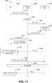
- FIG. 11 illustrates examples of a system 1100 for performing an RACH-less HO procedure.
- a measurement procedure associated with a UE 1125 may be configured using a source cell, S-Cell 1150 (and/or a source gNB, S-gNB).
- the UE 1125 may be configured to perform the RACH-less HO procedure using an RRC parameter (e.g., an rach-Less RRC parameter, an rach-Skip RRC parameter, etc.).
- an RRC parameter e.g., an rach-Less RRC parameter, an rach-Skip RRC parameter, etc.
- the UE 1125 may trigger (and/or generate) a measurement report 1102.
- the measurement report 1102 may be transmitted to the S-Cell 1150.
- the measurement report 1102 may comprise one or more beam measurement results associated with a target cell, T-Cell 1175 (and/or a target gNB, T-gNB).
- the measurement report 1102 may comprise one or more of a beam identifier, a Synchronization Signal Block (SSB) identifier, a CSI-RS identifier, an SSB measurement result, a CSI-RS measurement result, a TCI state, etc.
- SSB Synchronization Signal Block
- the S-Cell 1150 may make an HO decision 1104 based upon the measurement report 1102 and/or RRM information.
- the HO decision 1104 may correspond to a decision to perform an HO.
- the HO decision 1104 may correspond to a decision not to perform an HO.
- the S-Cell 1150 may issue (e.g., transmit) an HO request message 1106 (e.g., a HandoverPreparationInformation message) to the T-Cell 1175.
- the HO request message 1106 may be generated by the S-Cell 1150 based upon the HO decision 1104 and/or the measurement report 1102.
- the HO request message 1106 may comprise information associated with (preparation of) the T-Cell 1175 performing an HO.
- the HO request message 1106 may comprise one or more second beam measurement results associated with the T-Cell 1175 and/or the UE 1125.
- the one or more second beam measurement results may be the same as the one or more beam measurement results.
- the one or more second beam measurement results may be different than the one or more beam measurement results.
- the T-Cell 1175 may perform admission control 1108.
- the admission control 1108 may be performed by configuring one or more RACH resources and/or by reserving a C-RNTI and/or an RACH preamble for the UE 1125.
- the T-Cell 1175 may prepare the HO with L1/L2 (responsive to receiving the HO request 1106 and/or performing the admission control 1108). Alternatively and/or additionally, the T-Cell 1175 may transmit an HO request ACK (HO ACK) 1110 (e.g., a HandoverCommand message) to the S-Cell 1150.
- the HO ACK 1110 may comprise a timing adjustment indication (e.g., a TA indication) and/or one or more pre-allocated UL grants.
- the one or more pre-allocated UL grants may be associated with one or more beams.
- the T-Cell 1175 may generate an RRC reconfiguration message.
- the RRC reconfiguration message may comprise mobility control information associated with performing the HO.
- the HO ACK 1110 may comprise the RRC reconfiguration message.
- the one or more pre-allocated UL grants may be one or more periodic UL resources.
- the S-Cell 1150 may transmit a DL allocation message 1112 to the UE 1125.
- the DL allocation message 1112 may be associated with allocating DL data to the UE.
- the DL data may be allocated to the UE to transmit a second RRC reconfiguration message 1114 to the UE 1125.
- the second RRC reconfiguration message 1114 may be the same as the RRC reconfiguration message (comprised within the HO ACK 1110). Alternatively and/or additionally, the second RRC reconfiguration message 1114 may be different than the RRC reconfiguration message.
- the second RRC reconfiguration message 1114 may be transmitted, by the S-Cell 1150, to the UE 1125.
- one or more HO parameters may be transmitted to the UE 1125, by the S-Cell 1150, in association with the second RRC reconfiguration message 1114.
- the one or more HO parameters and/or the second RRC reconfiguration message 1114 may be comprised within a (single) message transmitted to the UE 1125.
- the one or HO parameters and/or the second RRC reconfiguration message 1114 may be transmitted to the UE 1125 separately.
- the one or more HO parameters and/or the second RRC reconfiguration message 1114 may comprise a command to perform the HO (e.g., an HO command).
- the one or more HO parameters may comprise one or more of a new C-RNTI, one or more target gNB security algorithm identifiers, a dedicated RACH preamble, one or more target eNB SIBs, etc.
- the second RRC reconfiguration message 1114 may comprise the timing adjustment indication (and/or a second timing adjustment indication) and/or the one or more pre-allocated UL grants (and/or one or more second pre-allocated UL grants) for accessing the T-Cell 1175.
- the UE 1125 may perform one or more operations 1116 associated with determining one or more UL grants associated with the T-Cell 1175. If the one or more pre-allocated UL grants (and/or the one or more second pre-allocated UL grants) for accessing the T-Cell 1175 are comprised within the second RRC reconfiguration message 1114, the one or more operations 1116 may comprise calculating the one or more pre-allocated UL grants (and/or the one or more second pre-allocated UL grants) based upon the second RRC reconfiguration message 1114.
- the one or more pre-allocated UL grants (and/or the one or more second pre-allocated UL grants) for accessing the T-Cell 1175 are comprised within the second RRC reconfiguration message 1114
- the one or more pre-allocated UL grants (and/or the one or more second pre-allocated UL grants) may be calculated based upon the second RRC reconfiguration message 1114.
- the one or more operations 1116 may comprise monitoring a PDCCH of the T-Cell 1175 to receive one or more UL grants 1126 from the T-Cell 1175.
- the UE 1125 may monitor the PDCCH of the T-Cell 1175 and/or the one or more UL grants 1126 may be received from the T-Cell 1175.
- the UE 1125 may transmit an RRC reconfiguration complete message 1118 (e.g., an HO complete message) to the T-Cell 1175 using the one or more pre-allocated UL grants (and/or the one or more second pre-allocated UL grants) and/or using the one or more UL grants 1126.
- RRC reconfiguration complete message 1118 e.g., an HO complete message
- the RRC reconfiguration complete message 1118 may be transmitted to the T-Cell 1175 using the one or more pre-allocated UL grants (and/or the one or more second pre-allocated UL grants).
- the RRC reconfiguration complete message 1118 may be transmitted to the T-Cell 1175 using the one or more UL grants 1126 received via PDCCH monitoring.
- the RRC reconfiguration complete message 1118 may be associated with an HO confirmation corresponding to the HO.
- one or more HO complete operations 1120 may be performed.
- the one or more HO complete operations 1120 may comprise the T-Cell 1175 verifying a C-RNTI (e.g., the new C-RNTI, a C-RNTI different than the new C-RNTI, etc.) comprised within the RRC reconfiguration complete message 1118.
- the HO procedure may be completed (for the UE 1125) responsive to the one or more HO complete operations 1120 being performed.
- the UE may monitor 1122 a (initial) PDCCH 1124 for DL and/or UL data scheduling. For example, information associated with DL and/or UL data scheduling may be received via the monitoring 1122 the PDCHH 1124.
- the UE 1125 may transmit data to the T-Cell 1175 and/or the T-Cell 1175 may receive the data from the UE 1125.
- the T-Cell 1175 may transmit data to the UE 1125 and/or the UE may receive the data from the T-Cell 1175.
- FIG. 12 illustrates examples of a system 1200 for performing the RACH-less HO procedure using the UE 1125, the S-Cell 1150 and/or the T-Cell 1175.
- the UE 1125 may not initiate a random access procedure due to a pending scheduling request 1202.
- the UE 1125 may access the T-Cell 1175 using the one or more pre-allocated UL grants (and/or the one or more second pre-allocated UL grants) in order to perform the (RACH-less) HO (if the one or more pre-allocated UL grants (and/or the one or more second pre-allocated UL grants) for accessing the T-Cell 1175 are comprised within the second RRC reconfiguration message 1114).
- the UE may monitor the PDCCH of the T-Cell 1175 to receive (e.g., acquire) the one or more UL grants 1126 (if the one or more pre-allocated UL grants (and/or the one or more second pre-allocated UL grants) for accessing the T-Cell 1175 are not comprised within the second RRC reconfiguration message 1114).
- the UE 1125 may transmit the RRC reconfiguration complete message 1118 (e.g., the HO complete message) via the one or more pre-allocated UL grants (and/or the one or more second pre-allocated UL grants) comprised within the second RRC reconfiguration message 1114 and/or via the one or more UL grants 1126 received via PDCCH monitoring.
- the RRC reconfiguration complete message 1118 e.g., the HO complete message
- the UE 1125 may transmit the RRC reconfiguration complete message 1118 (e.g., the HO complete message) via the one or more pre-allocated UL grants (and/or the one or more second pre-allocated UL grants) comprised within the second RRC reconfiguration message 1114 and/or via the one or more UL grants 1126 received via PDCCH monitoring.
- a PDCCH transmission 1204 may be transmitted by the T-Cell 1175 to the UE 1125.
- the PDCCH transmission 1204 may be associated with the one or more HO complete operations 1120 and/or may be performed to verify a C-RNTI (e.g., the new C-RNTI, a C-RNTI different than the new C-RNTI, etc.) comprised within the RRC reconfiguration complete message 1118.
- the HO procedure may be complete responsive to the PDCCH transmission 1204 being transmitted to the UE 1125.
- the RACH-less HO procedure may result in high HO performance with 0ms interruption, lower latency, higher efficiency and/or higher reliability than other HO procedures.
- beamforming may be utilized to increase antenna gain. Accordingly, beam management may be necessary for a network and/or the UE 1125 to determine one or more beams available for UL data transmission and/or DL data transmission. As illustrated in FIG. 11 , the UE 1125 may provide the measurement report 1102, comprising the one or more beam measurement results, to the S-Cell 1150. The S-Cell 1150 may make the HO decision 1104 based upon the measurement report 1102 (and/or the RRM information).
- the S-Cell 1150 may provide the measurement report 1102 to the T-Cell 1175 via the HO request message 1106.
- the measurement report 1102 may be included in the HO request message 1106 transmitted by the S-Cell 1150 to the T-Cell 1175.
- the T-Cell 1175 may allocate one or more UL grants on a PDCCH via one or more DL signals associated with one or more beams indicated by the one or more beam measurement results for the UE 1125. Alternatively and/or additionally, the T-Cell 1175 may pre-allocate one or more pre-allocated UL grants associated with one or more DL signals (e.g., SSB and/or CSI-RS) of the T-Cell 1175 based upon the one or more beam measurement results. The one or more DL signals may be associated with one or more beams.
- DL signals e.g., SSB and/or CSI-RS
- the T-Cell 1175 may provide the one or more pre-allocated UL grants (and/or an association between the one or more pre-allocated UL grants and one or more identifications (e.g., IDs) of the one or more DL signals) to the S-Cell 1150 (via the HO ACK 1110).
- the S-Cell 1150 may provide the one or more pre-allocated UL grants (and/or the association between the one or more pre-allocated UL grants and the one or more identifications (e.g., IDs) of the one or more DL signals) to the UE 1125 (via the DL allocation message 1112 and/or the second RRC reconfiguration message 1114.
- the one or more pre-allocated UL grants may be provided (to the UE via the second RRC reconfiguration message 1114). Alternatively and/or additionally, the one or more pre-allocated UL grants may not be provided (to the UE).
- the UE 1125 Prior to receiving an indication to assign one or more beams for PDCCH monitoring in the T-Cell 1175 (e.g., an indication of TCI state for UE-specific PDCCH), the UE 1125 may monitor a PDCCH of the T-Cell 1175 (to receive one or more UL grants during the RACH-less HO procedure, before transmitting the RRC reconfiguration complete message 1118 (e.g., the HO complete message).
- the UE 1125 may monitor a PDCCH of the T-Cell 1175 after RACH-less HO is completed (e.g., after transmitting the RRC reconfiguration complete message 1118 (e.g., the HO complete message).
- the UE may monitor a PDCCH of the T-Cell 1175 on one or more specific beams associated with the one or more DL signals.
- the UE 1125 If the one or more pre-allocated UL grants are not provided to the UE 1125 (and/or the UE 1125 is not configured with the one or more pre-allocated UL grants), which beam (and/or which beams) the UE 1125 should use to monitor the PDCCH of the T-Cell 1175 for acquiring the one or more UL grants 1126 remains unclear in existing technology.
- the UE the one or more pre-allocated UL grants are provided to the UE 1125 (and/or the UE 1125 is configured with the one or more pre-allocated UL grants), which beam (and/or which beams) the UE 1125 should use to monitor the PDCCH of the T-Cell 1175 for confirming that the RACH-less HO procedure is completed and/or for receiving the PDCCH transmission 1204 remains unclear in existing technology.
- An initial PDCCH beam associated with the T-Cell 1175 may be determined by identifying a beam, from a candidate list of beams, indicated by the second RRC reconfiguration message 1114 (e.g., the HO command), for monitoring a PDCCH of the T-Cell 1175.
- the second RRC reconfiguration message 1114 may be indicative of a TCI state corresponding to the beam for PDCCH monitoring.
- a PDCCH of the T-Cell 1175 may be monitored using a PDCCH beam that was (previously) used for monitoring a PDCCH of the S-Cell 1150.
- a PDCCH of the T-Cell 1175 may be monitored using a beam associated with the one or more pre-allocated UL grants.
- a PDCCH may be monitored using one or more beams associated with a DL signal associated with a measurement report.
- a UE may transmit a measurement report to a network prior to performing an RACH-less HO procedure.
- a target cell may transmit a signal on a PDCCH to the UE based upon the measurement report.
- the UE may monitor the PDCCH of the target cell using a target beam (e.g., a best beam) associated with the measurement report (and/or the target cell may transmit the signal on the PDCCH to the UE using the target beam).
- a target beam e.g., a best beam
- the target beam may be selected from amongst one or more beams of the measurement report. Alternatively and/or additionally, the target beam may be associated with a highest quality of one or more qualities associated with the one or more beams. For example, the target beam may be associated with a quality that is higher than one or more other qualities of one or more other beams, different than the target beam, of the one or more beams.
- the one or more qualities associated with the one or more beams may correspond to one or more RSRPs associated with the one or more beams. Alternatively and/or additionally, the target beam may be associated with a highest RSRP of one or more RSRPs associated with the one or more beams.
- the target beam may be associated with an RSRP that is higher than one or more other RSRPs of one or more other beams, different than the target beam, of the one or more beams.
- the one or more qualities (and/or the one or more RSRPs) may be determined (e.g., measured) after the UE synchronizes with (and/or to) the target cell.
- the measurement report may comprise a beam list.
- the beam list may be indicative of the one or more beams.
- an order of the beam list may be based upon the one or more qualities (and/or the one or more RSRPs).
- the target beam may be a first beam of the beam list (e.g., the target beam may be at the top of the beam list and/or the target beam may be in a first field of the beam list).
- the target beam may be a last beam of the beam list (e.g., the target beam may be at the bottom of the beam list and/or the target beam may be in a last field of the beam list).
- the UE 1125 may monitor a PDCCH on the target beam in the measurement report 1102.
- the UE 1125 may monitor a PDCCH on the target beam in the measurement report 1102.
- the UE 1125 may monitor a PDCCH on the target beam in the measurement report 1102 to receive the one or more UL grants 1126 and/or the UE 1125 may transmit the RRC reconfiguration complete message 1118 (e.g., the HO complete message) based upon the one or more UL grants 1126 (e.g., the one or more operations 1116 may comprise monitoring a PDCCH on the target beam in the measurement report 1102 to receive the one or more UL grants 1126).
- the RRC reconfiguration complete message 1118 e.g., the HO complete message
- the UE may monitor a PDCCH on the target beam in the measurement report after synchronizing with (and/or to) the target cell.
- the UE may be provided with one or more pre-allocated UL grants (via an RRC reconfiguration message (such as the second RRC reconfiguration message 1114 in FIG. 11 ) and/or the UE may monitor a PDCCH on the target beam in the measurement report (after being provided with the one or more pre-allocated UL grants and/or after being configured with the one or more pre-allocated UL grants).
- an RRC reconfiguration message such as the second RRC reconfiguration message 1114 in FIG. 11
- the UE may monitor a PDCCH on the target beam in the measurement report (after being provided with the one or more pre-allocated UL grants and/or after being configured with the one or more pre-allocated UL grants).
- the UE may monitor a PDCCH on each beam of the one or more beams (of the beam list) included in the measurement report.
- the UE may perform beam sweeping to monitor one or more PDCCHs on the one or more beams included in the measurement report.
- the UE 1125 may monitor a PDCCH on each beam included in the measurement report 1102 (e.g., by performing beam sweeping).
- the UE 1125 may monitor a PDCCH on each beam included in the measurement report 1102 (e.g., by performing beam sweeping).
- the UE 1125 may monitor a PDCCH on each beam included in the measurement report 1102 (e.g., by performing beam sweeping) to receive the one or more UL grants 1126 and/or the UE 1125 may transmit the RRC reconfiguration complete message 1118 (e.g., the HO complete message) based upon the one or more UL grants 1126 (e.g., the one or more operations 1116 may comprise monitoring a PDCCH on each beam included in the measurement report 1102 to receive the one or more UL grants 1126).
- the RRC reconfiguration complete message 1118 e.g., the HO complete message
- the UE may monitor a PDCCH on each beam included in the measurement report (e.g., by performing beam sweeping) after synchronizing with (and/or to) the target cell.
- the UE may be provided with one or more pre-allocated UL grants (via an RRC reconfiguration message, such as the second RRC reconfiguration message 1114 in FIG. 11 ) and/or the UE may monitor a PDCCH on each beam included in the measurement report (e.g., by performing beam sweeping) (after being provided with the one or more pre-allocated UL grants and/or after being configured with the one or more pre-allocated UL grants).
- an RRC reconfiguration message such as the second RRC reconfiguration message 1114 in FIG. 11
- the UE may monitor a PDCCH on each beam included in the measurement report (e.g., by performing beam sweeping) (after being provided with the one or more pre-allocated UL grants and/or after being configured with the one or more pre-allocated UL grants).
- the UE may monitor a PDCCH on a qualified beam of the one or more beams (of the beam list) included in the measurement report.
- the qualified beam may be associated with a quality that is greater than a threshold quality.
- the qualified beam may be associated with an RSRP that is greater than a threshold RSRP.
- the UE may perform beam sweeping to monitor a PDCCH on the qualified beam included in the measurement report.
- the UE 1125 may monitor a PDCCH on the qualified beam included in the measurement report 1102.
- the UE 1125 may monitor a PDCCH on the qualified beam included in the measurement report 1102.
- the UE 1125 may monitor a PDCCH on the qualified beam included in the measurement report 1102 to receive the one or more UL grants 1126 and/or the UE may transmit the RRC reconfiguration complete message 1118 (e.g., the HO complete message) based upon the one or more UL grants 1126 (e.g., the one or more operations 1116 may comprise monitoring a PDCCH on the qualified beam included in the measurement report 1102 to receive the one or more UL grants 1126).
- the RRC reconfiguration complete message 1118 e.g., the HO complete message
- the UE may monitor a PDCCH on the qualified beam included in the measurement report after synchronizing with (and/or to) the target cell.
- the UE may be provided with one or more pre-allocated UL grants (via an RRC reconfiguration message, such as the second RRC reconfiguration message 1114 in FIG. 11 ) and/or the UE may monitor a PDCCH on the qualified beam included in the measurement report (after being provided with the one or more pre-allocated UL grants and/or after being configured with the one or more pre-allocated UL grants).
- an RRC reconfiguration message such as the second RRC reconfiguration message 1114 in FIG. 11
- the UE may monitor a PDCCH on the qualified beam included in the measurement report (after being provided with the one or more pre-allocated UL grants and/or after being configured with the one or more pre-allocated UL grants).
- a PDCCH may be monitored using one or more beams associated with a DL signal (of a target cell) configured in an RRC reconfiguration message.
- a UE may transmit a measurement report to a network prior to performing an RACH-less HO procedure.
- the target cell may determine one or more beams to be used by the UE for PDCCH monitoring (based upon the measurement report).
- the target cell may indicate (to the UE) (e.g., via a TCI state, indicated by a TCI State ID field (e.g., TCI-StateID)) the one or more beams to be used by the UE for PDCCH monitoring.
- TCI State ID field e.g., TCI-StateID
- the target cell may include beam information (e.g., one or more beam identifiers, one or more DL signal identifiers, one or more SSB identifiers, one or more CSI-RS identifiers, a TCI state indication (for PDCCH reception for a CORESET of the target cell), a candidate list of beams (e.g., a list of TCI-StateID fields, such as tci-StatesPDCCH, etc.)) in an RRC reconfiguration message.
- beam information e.g., one or more beam identifiers, one or more DL signal identifiers, one or more SSB identifiers, one or more CSI-RS identifiers, a TCI state indication (for PDCCH reception for a CORESET of the target cell), a candidate list of beams (e.g., a list of TCI-StateID fields, such as tci-StatesPDCCH, etc.)) in an RRC recon
- the UE may receive the RRC reconfiguration message comprising the beam information.
- the target cell may transmit the RRC reconfiguration message to the UE.
- the target cell may transmit the RRC reconfiguration message to a source cell (within an HO ACK message) and/or the source cell may transmit the RRC reconfiguration message to the UE.
- the UE may determine the one or more beams to be used for PDCCH monitoring based upon the beam information within the RRC reconfiguration message.
- the UE may monitor the PDCCH of the target cell using a target beam associated with the RRC reconfiguration message.
- the target beam may be determined based upon the beam information of the RRC reconfiguration message.
- the target beam may be selected from amongst one or more beams of the beam information of the RRC reconfiguration message.
- the one or more beams of the beam information may be included in the candidate list of beams of the beam information (e.g., the candidate list of beams may comprise indications of the one or more beams).
- the target beam may be associated with a highest quality of one or more qualities associated with the one or more beams (included in the candidate list of beams) of the beam information.
- the target beam may be associated with a quality that is higher than one or more other qualities of one or more other beams, different than the target beam, of the one or more beams (included in the candidate list of beams) of the beam information.
- the one or more qualities associated with the one or more beams may correspond to one or more RSRPs associated with the one or more beams.
- the target beam may be associated with a highest RSRP of one or more RSRPs associated with the one or more beams (included in the candidate list of beams) of the beam information.
- the target beam may be associated with an RSRP that is higher than one or more other RSRPs of one or more other beams, different than the target beam, of the one or more beams (included in the candidate list of beams) of the beam information.
- the target beam may be in a first (e.g., initial) field of the beam information (and/or the candidate list of beams).
- the target beam may be a last field of the beam information (and/or the candidate list of beams).
- the UE may select a qualified beam based upon the beam information for PDCCH monitoring (and/or the UE may monitor a PDCCH on the qualified beam).
- the UE may monitor a PDCCH on each beam of the one or more beams (included in the candidate list of beams) of the beam information (e.g., by performing beam sweeping).
- the UE 1125 may monitor a PDCCH on each beam indicated by beam information in the second RRC reconfiguration message 1114 (e.g., by performing beam sweeping).
- the UE 1125 may monitor a PDCCH on each beam indicated by beam information in the second RRC reconfiguration message 1114 (e.g., by performing beam sweeping) to receive the one or more UL grants 1126 and/or the UE 1125 may transmit the RRC reconfiguration complete message 1118 (e.g., the HO complete message) based upon the one or more UL grants 1126 (e.g., the one or more operations 1116 may comprise monitoring a PDCCH on each beam indicated by the beam information in the second RRC reconfiguration message 1114 to receive the one or more UL grants 1126).
- the RRC reconfiguration complete message 1118 e.g., the HO complete message
- the UE may monitor a PDCCH on each beam indicated by beam information in the RRC reconfiguration message (e.g., by performing beam sweeping) after synchronizing with (and/or to) the target cell.
- the UE may be provided with one or more pre-allocated UL grants and/or the UE may monitor a PDCCH on each beam indicated by beam information in the RRC reconfiguration message (e.g., by performing beam sweeping) (after being provided with the one or more pre-allocated UL grants and/or after being configured with the one or more pre-allocated UL grants).
- the RRC reconfiguration message may comprise a candidate list of beams for PDCCH monitoring indicative of one or more candidate beams.
- the RRC reconfiguration message may be indicative of one or more second beams, of the one or more candidate beams (of the candidate list of beams for PDCCH monitoring) that should be used for PDCCH monitoring (in the target cell).
- the beam information may be included in an HO ACK message.
- a PDCCH may be monitored using one or more beams associated with a qualified DL signal (of a target cell) (e.g. the PDCCH may be monitored using the one or more beams after the UE synchronizes to and/or with the target cell).
- RACH-less HO may be configured.
- a UE may perform synchronization with (and/or to) a target cell after receiving an RRC reconfiguration message (from the target cell and/or from a source cell). Responsive to (and/or after) performing synchronization with (and/or to) the target cell, the UE may estimate and/or measure one or more DL signals of the target cell.
- the UE may (then) monitor one or more PDCCHs on one or more beams associated with one or more qualified DL signals (of the target cell) which may be estimated and/or measured after performing synchronization with (and/or to) the target cell.
- the UE may perform synchronization with (and/or to) the target cell.
- the UE may (then) estimate and/or measure one or more beams associated with one or more DL signals of the target cell to determine a target beam for monitoring a PDCCH.
- the target beam may be associated with a highest quality of one or more qualities associated with the one or more beams.
- the target beam may be associated with a quality that is higher than one or more other qualities of one or more other beams, different than the target beam, of the one or more beams.
- the one or more qualities associated with the one or more beams may correspond to one or more RSRPs associated with the one or more beams.
- the target beam may be associated with a highest RSRP of one or more RSRPs associated with the one or more beams.
- the target beam may be associated with an RSRP that is higher than one or more other RSRPs of one or more other beams, different than the target beam, of the one or more beams.
- the UE may perform synchronization with (and/or to) the target cell.
- the UE may (then) estimate and/or measure the one or more beams to select a qualified beam for monitoring a PDCCH.
- the qualified beam may be associated with a quality that is greater than a threshold quality.
- the qualified beam may be associated with an RSRP that is greater than a threshold RSRP.
- the one or more beams may be configured in the RRC reconfiguration message (e.g., the RRC reconfiguration message may be indicative of the one or more beams).
- the one or more beams may be included in a measurement report (e.g., the measurement report may be indicative of the one or more beams).
- the one or more beams may be configured by the source cell (e.g., the one or more beams may be configured before receiving the RRC reconfiguration message).
- the RRC reconfiguration message may comprise a candidate list of beams for PDCCH monitoring indicative of one or more candidate beams.
- the RRC reconfiguration message may be indicative of one or more second beams, of the one or more candidate beams (of the candidate list of beams for PDCCH monitoring) that should be used for PDCCH monitoring (in the target cell).
- the UE may trigger and/or generate the measurement report.
- a UE may monitor a PDCCH using one or more beams associated with a DL signal (of a source cell) (e.g., the beam may be configured for PDCCH monitoring in the source cell).
- the source cell may transmit information to a target cell.
- the information may be transmitted to the target cell in association with transmission of an HO request message to the target cell (e.g., the HO request message may comprise the information and/or the information may be transmitted separately from the HO request message to the target cell).
- the information may be indicative of one or more beams, used by the UE for PDCCH monitoring of the source cell, associated with a DL signal of the source cell.
- the target cell may transmit a signal on a PDCCH of the one or more beams, indicated by the source cell (via the information and/or the HO request message).
- the information may be indicative of one or more beams that the UE is configured to use for PDCCH monitoring of the source cell.
- the target cell may be aware that the UE may monitor a PDCCH on the one or more beams if an RACH-less HO procedure is not completed.
- the target cell may transmit a signal on a PDCCH of the one or more beams that the UE is configured to use for PDCCH monitoring of the source cell.
- the UE may monitor a PDCCH on one or more beams of the target cell, associated with the DL signal of the source cell, configured for PDCCH monitoring in the source cell (e.g., that the UE is configured to use for PDCCH monitoring in the source cell).
- the UE 1125 may monitor one or more PDCCHs on the one or more beams associated with a DL signal of the S-Cell 1150 configured for PDCCH monitoring.
- the UE 1125 may monitor one or more PDCCHs on the one or more beams associated with the DL signal of the S-Cell 1150 configured for PDCCH monitoring.
- the UE 1125 may monitor one or more PDCCHs on the one or more beams associated with the DL signal of the S-Cell 1150 configured for PDCCH monitoring to receive the one or more UL grants 1126 and/or the UE 1125 may transmit the RRC reconfiguration complete message 1118 (e.g., the HO complete message) based upon the one or more UL grants 1126 (e.g., the one or more operations 1116 may comprise monitoring one or more PDCCHs on the one or more beams associated with the DL signal of the S-Cell 1150 configured for PDCCH monitoring to receive the one or more UL grants 1126).
- the RRC reconfiguration complete message 1118 e.g., the HO complete message
- one or more latest TCI states for PDCCH reception configured for the source cell may be used as (and/or may be used to determine) one or more TCI states for PDCCH reception for the target cell.
- one or more latest beams for PDCCH reception configured for the source cell may be used as (and/or may be used to determine) the one or more beams for PDCCH reception for the target cell.
- the UE may monitor one or more PDCCHs on the one or more beams associated with the DL signal of the source cell that the UE is configured to use for PDCCH monitoring of the source cell after synchronizing with (and/or to) the target cell.
- the UE may be provided with one or more pre-allocated UL grants (via an RRC reconfiguration message (such as the second RRC reconfiguration message 1114 in FIG. 11 ) and/or the UE may monitor one or more PDCCHs on the one or more beams associated with the DL signal of the source cell that the UE is configured to use for PDCCH monitoring of the source cell (after being provided with the one or more pre-allocated UL grants and/or after being configured with the one or more pre-allocated UL grants).
- an RRC reconfiguration message such as the second RRC reconfiguration message 1114 in FIG. 11
- the one or more beams associated with the DL signal of the source cell may be associated with a DL signal of the target cell.
- a PDCCH may be monitored using one or more beams associated with a DL signal (of a target cell) which is associated with one or more pre-allocated UL grants.
- the target cell may provide the one or more UL grants to a UE and/or configure the UE with the one or more pre-allocated UL grants for transmission of an RRC reconfiguration complete message.
- the target cell may allocate the one or more pre-allocated UL grants associated with a DL signal (of the target cell) via an HO ACK message transmitted to a source cell.
- the source cell may transmit the one or more pre-allocated UL grants associated with the DL signal (of the target cell) to the UE (e.g., the one or more pre-allocated UL grants may be comprised within an RRC reconfiguration message transmitted by the source cell to the UE.
- the UE may monitor one or more PDCCH on one or more beams associated with the DL signal (of the target cell) which is associated with the one or more pre-allocated UL grants.
- An association e.g., a relationship between the DL signal (of the target cell) for PDCCH monitoring and the one or more pre-allocated UL grants may be indicated by the RRC reconfiguration message.
- a target DL signal (e.g., a best DL signal) may be selected by the UE from the multiple DL signals for PDCCH monitoring.
- the target DL signal may be associated with a highest quality of multiple qualities associated with the multiple DL signals.
- the target DL signal may be associated with a quality that is higher than one or more other qualities of the multiple qualities.
- the multiple qualities associated with the multiple DL signals may correspond to multiple RSRPs associated with the multiple DL signals.
- the target DL signal may be associated with a highest RSRP of the multiple RSRPs.
- the UE may select a beam (associated with the DL signal of the target cell), which may be used for transmission of the RRC reconfiguration complete message, to monitor a PDCCH (of the target cell).
- the UE may transmit the RRC reconfiguration complete message (to the target cell) on a first beam (via a pre-allocated UL grant) and/or the UE may monitor a PDCCH on the first beam.
- the UE 1125 when (e.g., prior to, during and/or after) the UE 1125 receives the second RRC reconfiguration message 1114 (from the S-Cell 1150), the UE 1125 may receive one or more pre-allocated UL grants (via the second RRC reconfiguration message 1114) associated with a second beam and/or the UE 1125 may monitor a PDCCH on the second beam.
- the UE may monitor a PDCCH on a qualified beam associated with the one or more pre-allocated UL grants. For example, the UE may select a qualified beam associated with the one or more pre-allocated UL grants to monitor a PDCCH.
- a qualified beam may be associated with a quality that is greater than a threshold quality.
- the qualified beam may be associated with an RSRP that is greater than a threshold RSRP.
- the UE may monitor a PDCCH on each beam associated with the one or more pre-allocated UL grants. For example, the UE may perform beam sweeping to monitor a PDCCH on each beam associated with the one or more pre-allocated UL grants.
- Each of the first embodiment, the second embodiment, the third embodiment, the fourth embodiment and the fifth embodiment may be implemented independently and/or separately. Alternatively and/or additionally, a combination of one or more of the first embodiment, the second embodiment, the third embodiment, the fourth embodiment and/or the fifth embodiment may be implemented.
- a UE may monitor a PDCCH on one or more beams in a target cell, where the one or more beams may be the same as one or more beams that are used for monitoring a PDCCH in the target cell during the RACH-less HO procedure. For example, the UE may monitor a PDCCH on a first beam to receive one or more UL grants for transmitting an RRC reconfiguration message, and/or the UE may monitor a PDCCH on the first beam after transmitting the RRC reconfiguration message.
- the UE may transmit a new measurement report (e.g., the new measurement report may comprise latest (e.g., most recent) beam measurement results) to the target cell via the RRC reconfiguration message (e.g., the RRC reconfiguration message may comprise the new measurement report).
- the UE may (then) monitor a PDCCH on one or more beams based upon the new measurement report (e.g., the one or more beams may be selected for PDCCH monitoring based upon the new measurement report and/or the latest beam measurement results).
- the UE may monitor a PDCCH on a target beam based upon the new measurement report (e.g., the target beam may be selected for PDCCH monitoring based upon the new measurement report and/or the latest beam measurement results).
- the target beam may have a highest quality of one or more qualities of one or more beams in the new measurement report.
- the target beam may have a highest RSRP of one or more RSRPs of one or more beams in the new measurement report.
- the UE may monitor a PDCCH on a qualified beam based upon the new measurement report (e.g., the qualified beam may be selected for PDCCH monitoring based upon the new measurement report and/or the latest beam measurement results).
- the qualified beam may be associated with a quality that is greater than a threshold quality.
- the qualified beam may be associated with an RSRP that is greater than a threshold RSRP.
- the UE may monitor a PDCCH on each beam included in the new measurement report (e.g., by performing beam sweeping).
- the UE may initiate a beam failure recovery (BFR) procedure and/or a random access procedure in the target cell when the RACH-less HO procedure is completed (e.g., after transmitting an RRC reconfiguration complete message).
- BFR beam failure recovery
- the random access procedure may be a contention-free random access procedure (e.g., one or more RACH resources may be configured in an RRC reconfiguration message).
- the random access procedure may be a contention-based random access procedure.
- one or more of the techniques provided herein for the UE to determine one or more beams to use for monitoring a PDCCH on the target cell may be used during the RACH-less HO procedure and/or after the RACH-less HO procedure is completed (e.g., for the UE to monitor an initial PDCCH on the target cell after the RACH-less HO procedure is completed).
- one or more of the techniques provided herein for the UE to determine one or more beams to use for monitoring a PDCCH on the target cell may be used when the UE adds a new SCell.
- the new SCell may be configured for the UE to monitor a PDCCH (e.g., the UE may monitor a PDCCH on the new SCell).
- the new SCell may be activated for the UE to monitor the PDCCH.
- the new SCell may not be cross-scheduled by one or more other SCells.
- one or more of the techniques provided herein for the UE to determine one or more beams to use for monitoring a PDCCH on the target cell may be used for performing an intra-cell HO procedure.
- the UE may determine one or more beams to monitor a PDCCH on the new SCell based upon beam information (e.g., the beam information may be included in the RRC reconfiguration message).
- a beam may refer to and/or may be associated with SSB resources and/or CSI-RS resources.
- a beam may refer to and/or may be a DL beam and/or a UL beam.
- a beam may refer to and/or may be a TX beam and/or an RX beam.
- a beam may be refer to and/or may be a network beam (e.g., NW beam) and/or a UE beam.
- a source cell (as used herein) may be replaced with a source gNB.
- a source gNB may be replaced with a source gNB.
- one or more techniques presented herein that are described as applying to a source cell may (also) be applied to a source gNB.
- a target cell (as used herein) may be replaced with a target gNB.
- a target gNB may be replaced with a target gNB.
- one or more techniques presented herein that are described as applying to a target cell may (also) be applied to a target gNB.
- a source cell (as used herein) may be replaced with a source eNB.
- a source eNB may be replaced with a source eNB.
- one or more techniques presented herein that are described as applying to a source cell may (also) be applied to a source eNB.
- a target cell (as used herein) may be replaced with a target eNB.
- a target eNB may be replaced with a target eNB.
- one or more techniques presented herein that are described as applying to a target cell may (also) be applied to a target eNB.
- a qualified beam may be a beam where a quality of the beam (e.g., SS-RSRP and/or CSI-RSRP) is above a quality threshold (e.g., rsrp-ThresholdSSB and/or csirs-Threshold).
- the qualified beam may be selected using a MAC layer and/or a PHY layer.
- a qualified DL signal may be a DL signal where a quality of the DL signal (e.g., SS-RSRP and/or CSI-RSRP) is above a quality threshold (e.g., rsrp-ThresholdSSB and/or csirs-Threshold).
- the qualified DL signal may be selected using a MAC layer and/or a PHY layer.
- FIG. 13 is a flow chart 1300 according to one exemplary embodiment from the perspective of a UE.
- a measurement report may be transmitted to a first cell (by the UE).
- a signal may be received in the first cell, wherein the signal comprises a parameter for RACH-less handover and/or a configuration of a second cell.
- a channel of the second cell on a beam may be monitored, wherein the beam is associated with a DL signal.
- the beam may be a target beam included in the measurement report.
- the target beam may be associated with a highest quality of one or more qualities, of a beam measurement result in the measurement report, associated with one or more beams of the measurement report.
- the target beam may be associated with a first field of a beam measurement result (e.g., a beam list) in the measurement report (e.g., the target beam may be in the first field of the beam measurement result and/or the first field of the beam measurement result may be indicative of the target beam).
- a beam measurement result e.g., a beam list
- the target beam may be in the first field of the beam measurement result and/or the first field of the beam measurement result may be indicative of the target beam.
- the target beam may be associated with a last field of a beam measurement result (e.g., a beam list) in the measurement report (e.g., the target beam may be in the last field of the beam measurement result and/or the last field of the beam measurement result may be indicative of the target beam).
- a beam measurement result e.g., a beam list
- the target beam may be in the last field of the beam measurement result and/or the last field of the beam measurement result may be indicative of the target beam.
- the beam may be a qualified beam included in the measurement report.
- the qualified beam may be associated with a quality that is greater than a threshold quality.
- the beam may correspond to (and/or may be) multiple beams included in the measurement report.
- the multiple beams may comprise each (and/or every) beam included in the measurement report (e.g., the channel of the second cell may be monitored on the multiple beams, which may be performed by performing beam sweeping).
- FIG. 14 is a flow chart 1400 according to one exemplary embodiment from the perspective of a UE.
- a signal may be received in a first cell, wherein the signal comprises a parameter for RACH-less handover and/or a configuration of a second cell.
- a channel of the second cell on a beam may be monitored, wherein the beam is associated with a DL signal.
- the beam may be configured (and/or included and/or indicated) in the signal.
- the beam may be a target beam of a list configured (and/or included and/or indicated) in the signal.
- the target beam may be associated with a highest quality of one or more qualities associated with one or more beams configured (and/or included and/or indicated) in the signal.
- the target beam may be associated with a first field of the list, wherein the list is a candidate list of the beam (e.g., a candidate list of beams).
- the target beam may be associated with a last field of the list, wherein the list is the candidate list of the beam (e.g., the candidate list of beams).
- the beam may be a qualified beam included in the signal.
- the qualified beam may be associated with a quality that is greater than a threshold quality.
- the beam may correspond to multiple beams included in the signal.
- the multiple beams may comprise each (and/or every) beam included in the signal (e.g., the channel of the second cell may be monitored on the multiple beams, which may be performed by performing beam sweeping).
- FIG. 15 is a flow chart 2300 according to one exemplary embodiment from the perspective of a UE.
- an indication may be received in a first cell, wherein the indication indicates a beam for monitoring a first channel (e.g., the indication may be indicative of the beam for monitoring the first channel).
- a signal may be received in the first cell, wherein the signal comprises a parameter for RACH-less handover and/or a configuration of a second cell.
- a second channel on the beam may be monitored.
- the beam may be associated with a DL signal of the first cell.
- the first channel may be a first PDCCH of the first cell.
- the second channel may be a second PDCCH of the second cell.
- the first PDCCH may be different than the second PDCCH.
- the first PDCCH may be the same as the second PDCCH.
- the indication may be a TCI state (and/or the indication may be indicative of the TCI state).
- FIG. 16 is a flow chart 1600 according to one exemplary embodiment from the perspective of a UE.
- a signal may be received in a first cell, wherein the signal comprises a parameter for RACH-less handover, a configuration of a second cell and/or a UL grant for the second cell.
- a channel of the second cell on a beam may be monitored, wherein the beam is associated with a DL signal of the second cell and/or the DL signal is associated with the UL grant.
- the beam may be configured (and/or included and/or indicated) in the signal.
- the beam may be a target beam if a number of beams (associated with the signal) is greater than one.
- the target beam may be associated with a highest quality of one or more qualities associated with one or more beams (associated with the signal).
- an association (e.g., a relationship) between the DL signal and the UL grant may be indicated by the signal.
- the beam may be used for monitoring the channel of the second cell and for receiving the signal in the first cell.
- the UE may synchronize with (and/or to) the second cell.
- the UE may transmit an RRC reconfiguration complete message to the second cell.
- the measurement report may comprise a beam measurement result.
- the measurement report may comprise information associated with the DL signal.
- the information may comprise an identifier associated with the DL signal and/or a quality (e.g., an RSRP) associated with the DL signal.
- a quality e.g., an RSRP
- the channel (and/or the first channel and/or the second channel) may be a PDCCH.
- the target beam may be associated with a highest quality of one or more qualities associated with one or more beams.
- the qualified beam may be associated with a quality that is greater than a threshold quality.
- the beam for monitoring the channel may be indicated using (and/or based upon) a TCI state.
- the DL signal may be (and/or may comprise) one or more DL signals.
- the DL signal may be (and/or may comprise) an SSB.
- the DL signal may be (and/or may comprise) a CSI-RS.
- the DL signal may refer to a beam.
- the signal may be an RRC reconfiguration message.
- the signal may comprise mobility control information.
- the signal may comprise a UL grant for the second cell.
- the signal includes one or more beam identifiers, one or more DL signal identifiers, one or more SSB identifiers, one or more CSI-RS identifiers, a TCI state indication and/or a candidate list of beams.
- the UL grant may be a pre-allocated UL grant.
- the UL grant may be periodic (e.g., the UL grant may be a periodic UL grant).
- the UE may be performing an RACH-less handover procedure.
- the parameter may be RACH-less, RACH-skip and/or RACH-skipSCG.
- the first cell may be a PCell, an SpCell and/or an SCell.
- the second cell may be a PCell, an SpCell and/or an SCell.
- the first cell may be a source cell, a source eNB and/or a source gNB.
- the second cell may be a target cell, a target eNB and/or a target gNB.
- a communication device may be provided, wherein the communication device may comprise a control circuit, a processor installed in the control circuit and/or a memory installed in the control circuit and coupled to the processor.
- the processor may be configured to execute a program code stored in the memory to perform method steps illustrated in FIG. 13 , FIG. 14 , FIG. 15 and/or FIG. 16 .
- the processor may execute the program code to perform some and/or all of the above-described actions and steps and/or others described herein.
- FIG. 17 is a flow chart 1700 according to one exemplary embodiment from the perspective of a UE.
- a signal to configure the UE to perform an RACH-less handover to a second cell may be received in a first cell, wherein the signal comprises a candidate list of beams for PDCCH monitoring in the second cell and/or the signal is indicative of a first beam of the candidate list of beams (to be used by the UE for PDCCH monitoring).
- a PDCCH in the second cell on the first beam may be monitored before receiving a MAC CE assigning a second beam for PDCCH monitoring in the second cell (e.g., the PDCCH in the second cell on the first beam may be monitored before receiving the MAC CE (comprising an instruction) to assign the second beam for PDCCH monitoring in the second cell).
- the device 300 includes a program code 312 stored in the memory 310.
- the CPU 308 may execute program code 312 (i) to receive, in a first cell, a signal to configure the UE to perform an RACH-less handover to a second cell, wherein the signal comprises a candidate list of beams for PDCCH monitoring in the second cell and/or the signal is indicative of a first beam of the candidate list of beams (to be used by the UE for PDCCH monitoring), and (ii) to monitor, in the second cell, a PDCCH on the first beam before receiving a MAC CE assigning a second beam for PDCCH monitoring in the second beam.
- the CPU 308 can execute the program code 312 to perform some and/or all of the above-described actions and steps and/or others described herein.
- the signal may be (and/or may comprise) an RRC reconfiguration message.
- the signal may configure RACH-less, RACH-skip and/or RACH-skipSCG (e.g., the signal may be indicative of RACH-less, RACH-skip and/or RACH-skipSCG).
- the candidate list of beams may be a TCI states PDCCH list (e.g., a list of TCI states).
- the first beam and/or the second beam may be a TCI state (and/or may be associated with a TCI state).
- the first beam may be associated with a first TCI state and/or the second beam may be associated with a second TCI state.
- the first TCI state may be different than the second TCI state.
- the first TCI state may be the same as the second TCI state.
- the MAC CE may be an indication of a TCI state for UE specific PDCCH (e.g., the MAC CE may be indicative of the TCI state).
- the MAC CE may comprise information indicative of a serving cell identification (e.g., a serving cell ID), a BWP identification (e.g., a BWP ID), a CORESET identification (e.g., a CORESET ID) and/or a TCI state identification (e.g., a TCI State ID).
- FIG. 18 is a flow chart 1800 according to one exemplary embodiment from the perspective of a UE.
- a first MAC CE assigning a first beam for PDCCH monitoring in a first cell may be received (e.g., the first MAC CE (comprising an instruction) to assign the first beam for PDCCH monitoring in the first cell may be received).
- a first PDCCH in the first cell on the first beam may be monitored based upon the first MAC CE.
- a signal to configure the UE to perform an RACH-less handover to a second cell may be received in the first cell.
- a second PDCCH in the second cell on the first beam may be monitored based upon the first MAC CE before receiving a second MAC CE assigning a second beam for PDCCH monitoring in the second cell (e.g., the second PDCCH in the second cell on the first beam may be monitored before receiving the second MAC CE (comprising an instruction) to assign the second beam for PDCCH monitoring in the second cell).
- the first PDCCH may be different than the second PDCCH. Alternatively and/or additionally, the first PDCCH may be the same as the second PDCCH.
- the device 300 includes a program code 312 stored in the memory 310.
- the CPU 308 may execute program code 312 (i) to receive a first MAC CE assigning a first beam for PDCCH monitoring in a first cell, (ii) to monitor, in the first cell, a first PDCCH on the first beam based upon the first MAC CE, (iii) to receive, in the first cell, a signal to configure the UE to perform an RACH-less handover to a second cell, and (iv) to monitor, in the second cell, a second PDCCH on the first beam based upon the first MAC CE before receiving a second MAC CE assigning a second beam for PDCCH monitoring in the second cell.
- the CPU 308 can execute the program code 312 to perform some and/or all of the above-described actions and steps and/or others described herein.
- the first MAC CE and/or the second MAC CE may be an indication of a TCI state for UE-specific PDCCH.
- the first MAC CE may be a first indication of a TCI state for UE-specific PDCCH and/or the second MAC CE may be a second indication of a TCI state for UE-specific PDCCH.
- the first indication of a TCI state for UE-specific PDCCH may be different than the second indication of a TCI state for UE-specific PDCCH.
- the first indication of a TCI state for UE-specific PDCCH may be the same as the second indication of a TCI state for UE-specific PDCCH.
- the first MAC CE may be received via the first cell, the second cell and/or a different cell.
- the second MAC CE may be received via the first cell, the second cell and/or a different cell.
- the first MAC CE may comprise first information indicative of a serving cell identification (e.g., a serving cell ID), a BWP identification (e.g., a BWP ID), a CORESET identification (e.g., a CORESET ID) and/or a TCI state identification (e.g., a TCI State ID).
- the second MAC CE may comprise second information indicative of a serving cell identification (e.g., a serving cell ID), a BWP identification (e.g., a BWP ID), a CORESET identification (e.g., a CORESET ID) and/or a TCI state identification (e.g., a TCI State ID).
- the first information may be different than the second information.
- the first information may be the same as the second information.
- the signal may be an RRC reconfiguration message.
- the signal may configure RACH-less, RACH-skip and/or RACH-skipSCG (e.g., the signal may be indicative of RACH-less, RACH-skip and/or RACH-skipSCG).
- FIG. 19 is a flow chart 1900 according to one exemplary embodiment from the perspective of a UE.
- a signal to configure the UE to perform an RACH-less handover to a second cell may be received in a first cell, wherein the signal comprises a UL grant (to be used in the second cell) and/or the UL grant is associated with a DL signal.
- a PDCCH in the second cell on a beam associated with the DL signal may be monitored.
- the device 300 includes a program code 312 stored in the memory 310.
- the CPU 308 may execute program code 312 (i) to receive, in a first cell, a signal to configure the UE to perform an RACH-less handover to a second cell, wherein the signal comprises a UL grant (to be used in the second cell) and/or the UL grant is associated with a DL signal, and (ii) to monitor, in the second cell, a PDCCH on a beam associated with the DL signal.
- the CPU 308 can execute the program code 312 to perform some and/or all of the above-described actions and steps and/or others described herein.
- the signal may be (and/or may comprise) an RRC reconfiguration message.
- the signal may configure RACH-less, RACH-skip and/or RACH-skipSCG (e.g., the signal may be indicative of RACH-less, RACH-skip and/or RACH-skipSCG).
- the UL grant may be a periodic UL grant (and/or the UL grant may be periodic).
- the UL grant may be a pre-allocated UL grant.
- the UL grant may be used for the second cell.
- the DL signal may be (and/or may comprise) an SSB.
- the DL signal may be (and/or may comprise) a CSI-RS.
- concurrent channels may be established based on pulse repetition frequencies.
- concurrent channels may be established based on pulse position or offsets.
- concurrent channels may be established based on time hopping sequences.
- concurrent channels may be established based on pulse repetition frequencies, pulse positions or offsets, and time hopping sequences.
- the various illustrative logical blocks, modules, and circuits described in connection with the aspects disclosed herein may be implemented within or performed by an integrated circuit ("IC"), an access terminal, or an access point.
- the IC may comprise a general purpose processor, a digital signal processor (DSP), an application specific integrated circuit (ASIC), a field programmable gate array (FPGA) or other programmable logic device, discrete gate or transistor logic, discrete hardware components, electrical components, optical components, mechanical components, or any combination thereof designed to perform the functions described herein, and may execute codes or instructions that reside within the IC, outside of the IC, or both.
- a general purpose processor may be a microprocessor, but in the alternative, the processor may be any conventional processor, controller, microcontroller, or state machine.
- a processor may also be implemented as a combination of computing devices, e.g., a combination of a DSP and a microprocessor, a plurality of microprocessors, one or more microprocessors in conjunction with a DSP core, or any other such configuration.
- a software module e.g., including executable instructions and related data
- other data may reside in a data memory such as RAM memory, flash memory, ROM memory, EPROM memory, EEPROM memory, registers, a hard disk, a removable disk, a CD-ROM, or any other form of computer-readable storage medium known in the art.
- a sample storage medium may be coupled to a machine such as, for example, a computer/processor (which may be referred to herein, for convenience, as a "processor") such the processor can read information (e.g., code) from and write information to the storage medium.
- a sample storage medium may be integral to the processor.
- the processor and the storage medium may reside in an ASIC.
- the ASIC may reside in user equipment.
- the processor and the storage medium may reside as discrete components in user equipment.
- any suitable computer-program product may comprise a computer-readable medium comprising codes relating to one or more of the aspects of the disclosure.
- a computer program product may comprise packaging materials.
Landscapes
- Engineering & Computer Science (AREA)
- Signal Processing (AREA)
- Computer Networks & Wireless Communication (AREA)
- Mobile Radio Communication Systems (AREA)
Claims (10)
- Verfahren einer Teilnehmerausrüstung, UE, umfassend:Empfangen eines ersten Medium-Access-Control-, MAC-, Steuerelements, CE, das einen ersten Strahl für eine Physical-Downlink-Control-Channel-, PDCCH-, Beobachtung in einer ersten Zelle zuweist (1805);Beobachten, in der ersten Zelle, eines ersten PDCCH auf dem ersten Strahl basierend auf dem ersten MAC-CE (1810); undEmpfangen, in der ersten Zelle, eines Signals, um die UE zu konfigurieren, eine zufallszugriffskanallose, RACH-less, Übergabe an eine zweite Zelle auszuführen (1815);gekennzeichnet durch:
Beobachten, in der zweiten Zelle, eines zweiten PDCCH auf dem ersten Strahl basierend auf dem ersten MAC-CE vor einem Empfangen eines zweiten MAC-CEs, das einen zweiten Strahl für eine PDCCH-Beobachtung in der zweiten Zelle zuweist (1820). - Verfahren gemäß Anspruch 1, wobei mindestens eins des ersten MAC-CEs oder des zweiten MAC-CEs eine Anzeige eines TCI-Status für einen UE-spezifischen PDCCH ist.
- Verfahren gemäß Anspruch 1 oder 2, wobei das erste MAC-CE über mindestens eine der ersten Zelle, der zweiten Zelle oder einer anderen Zelle empfangen wird; und/oder
wobei das zweite MAC-CE über mindestens eine der ersten Zelle, der zweiten Zelle oder einer anderen Zelle empfangen wird. - Verfahren gemäß einem der Ansprüche 1 bis 3, wobei mindestens eines des ersten MAC-CEs oder des zweiten MAC-CEs Informationen über mindestens eine einer Dienstzellenidentifikation, einer Bandbreitenteil-, BWP-, Identifikation, einer Steuerungsressourcensatz-, CORESET-, Identifikation oder einer TCI-Status-Identifikation aufweist.
- Verfahren gemäß einem der Ansprüche 1 bis 4, wobei das Signal eine Funkressourcensteuerungs-, RRC-, Rekonfigurationsnachricht ist; und/oder
wobei das Signal mindestens eins von RACH-less, RACH-skip oder RACH-skipSCG konfiguriert. - Verfahren einer Teilnehmerausrüstung, UE, umfassend:Empfangen, in einer ersten Zelle, eines Signals, um die UE zu konfigurieren, eine zufallszugriffskanallose, RACH-less, Übergabe an eine zweite Zelle auszuführen, wobei das Signal eine Funkressourcensteuerungs-, RRC-, Rekonfigurationsnachricht ist und eine Uplink-, UL-, Bewilligung aufweist;wobei eine Verknüpfung zwischen der UL-Bewilligung und einem Downlink-, DL-, Signal (1905) in der RRC-Rekonfigurationsnachricht angezeigt wird; undBeobachten, in der zweiten Zelle, eines PDCCH auf einem Strahl, der mit dem DL-Signal verknüpft ist (1910).
- Verfahren gemäß Anspruch 6, wobei das Signal mindestens eins von RACH-less, RACH-skip oder RACH-skipSCG konfiguriert.
- Verfahren gemäß Anspruch 6 oder 7, wobei die UL-Bewilligung mindestens eine einer periodischen UL-Bewilligung oder einer vorab zugewiesenen UL-Bewilligung ist; und/oder
wobei die UL-Bewilligung für die zweite Zelle verwendet wird. - Verfahren gemäß einem der Ansprüche 6 bis 8, wobei das DL-Signal mindestens eins von einem Synchronisationssignalblock, SSB, oder einem kanalzustandsinformationsbasierten Referenzsignal, CSI-RS, ist.
- Teilnehmerausrüstung, UE, aufweisend:eine Steuerungsschaltung (306);einen Prozessor (308), der in der Steuerungsschaltung (306) installiert ist; undeinen Speicher (310), der in der Steuerungsschaltung (306) installiert und mit dem Prozessor (308) verbunden ist;wobei der Prozessor (308) ausgelegt ist, einen Programm-Code (312), der in dem Speicher (310) gespeichert ist, auszuführen, um die in einem der vorstehenden Ansprüche definierten Verfahrensschritte auszuführen.
Applications Claiming Priority (1)
| Application Number | Priority Date | Filing Date | Title |
|---|---|---|---|
| US201862646719P | 2018-03-22 | 2018-03-22 |
Publications (2)
| Publication Number | Publication Date |
|---|---|
| EP3544218A1 EP3544218A1 (de) | 2019-09-25 |
| EP3544218B1 true EP3544218B1 (de) | 2020-10-21 |
Family
ID=65817762
Family Applications (1)
| Application Number | Title | Priority Date | Filing Date |
|---|---|---|---|
| EP19162549.0A Active EP3544218B1 (de) | 2018-03-22 | 2019-03-13 | Verfahren und vorrichtung zur pdcch-überwachung in einem drahtloskommunikationssystem |
Country Status (3)
| Country | Link |
|---|---|
| US (1) | US10972952B2 (de) |
| EP (1) | EP3544218B1 (de) |
| CN (1) | CN110300433B (de) |
Families Citing this family (43)
| Publication number | Priority date | Publication date | Assignee | Title |
|---|---|---|---|---|
| CN114745030B (zh) * | 2016-09-29 | 2024-08-20 | 日本电气株式会社 | 无线终端、基站及其方法 |
| US10966101B2 (en) | 2018-01-10 | 2021-03-30 | Apple Inc. | Mobile communication system, user equipment, base station, base band circuitry, methods, machine readable media and computer programs to communicate in a mobile communication system |
| US10979273B2 (en) * | 2018-03-23 | 2021-04-13 | Qualcomm Incorporated | Quasi co-location assumption during bandwidth part switching |
| US10939282B2 (en) * | 2018-04-05 | 2021-03-02 | Qualcomm Incorporated | Default value selection for medium access control-control element (MAC-CE) based parameter value selection |
| JP6918992B2 (ja) * | 2018-05-10 | 2021-08-11 | エルジー エレクトロニクス インコーポレイティド | 無線通信システムにおけるpucchリソースを構成する方法および装置 |
| CN113347664B (zh) | 2018-05-14 | 2023-09-15 | 中兴通讯股份有限公司 | 切换方法及装置 |
| US11228931B2 (en) * | 2018-08-10 | 2022-01-18 | Qualcomm Incorporated | On-demand physical layer reporting by a UE |
| CN110868739B (zh) * | 2018-08-27 | 2023-12-15 | 夏普株式会社 | 由用户设备执行的方法、用户设备以及切换命令生成方法 |
| WO2020102975A1 (en) * | 2018-11-20 | 2020-05-28 | Qualcomm Incorporated | Random access channel (rach) -less procedure |
| WO2020166899A1 (en) | 2019-02-13 | 2020-08-20 | Samsung Electronics Co., Ltd. | Method and apparatus for handling msga retransmissions during 2 step random access procedures in wireless communication system |
| EP3925281A1 (de) * | 2019-02-14 | 2021-12-22 | Telefonaktiebolaget Lm Ericsson (Publ) | Strahlbegrenzungen für rach-losen zugang |
| WO2020185002A1 (en) * | 2019-03-12 | 2020-09-17 | Samsung Electronics Co., Ltd. | Method and apparatus for performing communication in wireless communication system |
| JP7257274B2 (ja) * | 2019-06-27 | 2023-04-13 | 本田技研工業株式会社 | 通信システム、プログラム、及び情報処理方法 |
| US11375421B2 (en) * | 2019-08-16 | 2022-06-28 | Apple Inc. | Cell handover in a radio cellular system |
| US10973044B1 (en) * | 2019-10-03 | 2021-04-06 | Qualcomm Incorporated | Default spatial relation for SRS/PUCCH |
| WO2021070160A1 (en) * | 2019-10-11 | 2021-04-15 | Telefonaktiebolaget Lm Ericsson (Publ) | Systems and methods for updating active tci state for multi-pdcch based multi-trp |
| US20230134762A1 (en) * | 2019-10-12 | 2023-05-04 | Nokia Technologies Oy | Apparatus, Method, and Computer Program |
| JP6968135B2 (ja) * | 2019-10-21 | 2021-11-17 | シャープ株式会社 | 端末装置、基地局装置、および、方法 |
| CN118200968A (zh) * | 2019-11-08 | 2024-06-14 | 联发科技股份有限公司 | 用于移动通信的方法及装置 |
| US20220394562A1 (en) * | 2019-11-19 | 2022-12-08 | Google Llc | Device and Method of Configuring a Group Handover/Cell Reselection |
| KR20220103036A (ko) * | 2019-11-22 | 2022-07-21 | 광동 오포 모바일 텔레커뮤니케이션즈 코포레이션 리미티드 | 무선 통신 장치 및 방법 |
| US20230023719A1 (en) * | 2019-11-25 | 2023-01-26 | Samsung Electronics Co., Ltd. | Method and apparatus for configuring default beam for network cooperative communication |
| CN115053622A (zh) | 2020-02-03 | 2022-09-13 | 三星电子株式会社 | 用于在无线通信系统中执行通信的方法和装置 |
| US11368891B2 (en) | 2020-02-12 | 2022-06-21 | Apple Inc. | Primary cell switching in non-simultaneous uplink carrier aggregation scenarios |
| CN113260002B (zh) * | 2020-02-12 | 2022-05-24 | 维沃移动通信有限公司 | 小区切换方法和设备 |
| CN111901838B (zh) * | 2020-02-14 | 2024-09-10 | 中兴通讯股份有限公司 | 一种信令接收、发送方法及设备 |
| CN115136650A (zh) * | 2020-02-24 | 2022-09-30 | Oppo广东移动通信有限公司 | 一种传输控制方法、终端设备、网络设备 |
| US11671992B2 (en) * | 2020-04-08 | 2023-06-06 | Apple, Inc | Transmission configuration indicator (TCI) acquisition mechanism for secondary cell activation of a frequency range 2 (FR2) unknown cell |
| CN115836557A (zh) * | 2020-05-12 | 2023-03-21 | 中兴通讯股份有限公司 | 用于管理组播传输的系统和方法 |
| KR20210141106A (ko) * | 2020-05-15 | 2021-11-23 | 삼성전자주식회사 | 차세대 이동 통신 시스템에서 Conditional PSCell change 과정을 수행하는 방법 및 장치 |
| US20230146642A1 (en) * | 2020-05-20 | 2023-05-11 | Ntt Docomo, Inc. | Terminal, radio communication method, and base station |
| WO2021232433A1 (zh) * | 2020-05-22 | 2021-11-25 | Oppo广东移动通信有限公司 | 监听信道的方法、装置、设备及存储介质 |
| CN113973348B (zh) * | 2020-07-24 | 2024-05-31 | 华硕电脑股份有限公司 | 无线通信系统中用于移动性程序的方法和设备 |
| CN114390611B (zh) * | 2020-10-22 | 2024-02-02 | 大唐移动通信设备有限公司 | 小区切换方法、终端、基站、装置和存储介质 |
| CN116456285A (zh) * | 2020-12-07 | 2023-07-18 | 上海朗帛通信技术有限公司 | 一种用于无线通信的节点中的方法和装置 |
| CN116848934A (zh) * | 2021-01-14 | 2023-10-03 | 苹果公司 | 用于增强的直接辅小区激活的方法 |
| EP4280741A1 (de) * | 2021-01-17 | 2023-11-22 | JRD Communication (Shenzhen) Ltd | Verfahren zur konfiguration des tci-zustands in einem multi-trp-system |
| EP4305767A1 (de) * | 2021-03-11 | 2024-01-17 | Telefonaktiebolaget LM Ericsson (publ) | Strahlumschaltung für drahtlose kommunikation |
| CN115150953A (zh) * | 2021-03-31 | 2022-10-04 | 维沃移动通信有限公司 | 控制信道检测、指示方法、装置、终端及网络侧设备 |
| CN117296280A (zh) * | 2021-07-23 | 2023-12-26 | Oppo广东移动通信有限公司 | Pdcch监听方法、装置、设备及存储介质 |
| WO2023117779A2 (en) * | 2021-12-20 | 2023-06-29 | Nokia Technologies Oy | Lower layer rach-less inter-cell mobility |
| WO2024055275A1 (en) * | 2022-09-16 | 2024-03-21 | Qualcomm Incorporated | Network node based beam prediction for cell group setup |
| WO2024152308A1 (en) * | 2023-01-19 | 2024-07-25 | Nec Corporation | Devices and methods of communication |
Family Cites Families (23)
| Publication number | Priority date | Publication date | Assignee | Title |
|---|---|---|---|---|
| US8509791B2 (en) * | 2007-03-17 | 2013-08-13 | Qualcomm Incorporated | Handover in wireless communications |
| US20140112254A1 (en) * | 2011-06-17 | 2014-04-24 | Telefonaktiebolaget L M Ericsson (Publ) | Methods and nodes for random access |
| WO2015127987A1 (en) * | 2014-02-28 | 2015-09-03 | Nokia Solutions And Networks Oy | Techniques for rach (random access channel)-less synchronized handover for wireless networks |
| JP2015185956A (ja) * | 2014-03-20 | 2015-10-22 | 株式会社Nttドコモ | ユーザ装置及び基地局 |
| WO2015180104A1 (zh) * | 2014-05-29 | 2015-12-03 | 华为技术有限公司 | 一种网络节点间链路的处理装置及方法 |
| WO2016119219A1 (zh) * | 2015-01-30 | 2016-08-04 | 华为技术有限公司 | 通信方法、基站和用户设备 |
| EP3557907B1 (de) | 2016-04-12 | 2021-01-27 | Intel IP Corporation | Verfahren zur fortwährenden datenübertragung während übergabeoperationen |
| WO2017179951A1 (en) * | 2016-04-14 | 2017-10-19 | Samsung Electronics Co., Ltd. | Method and apparatus for transmitting and receiving signal through beamforming in communication system |
| CN109479309B (zh) * | 2016-07-13 | 2022-10-11 | 三星电子株式会社 | 在移动通信中使用的接入控制方法和装置 |
| US20180049079A1 (en) * | 2016-08-12 | 2018-02-15 | Qualcomm Incorporated | Handover in wireless communications |
| WO2018053692A1 (zh) * | 2016-09-20 | 2018-03-29 | 北京小米移动软件有限公司 | 数据传输方法、装置及系统 |
| US10849058B2 (en) * | 2016-11-03 | 2020-11-24 | Lg Electronics Inc. | Method and apparatus for transmitting and receiving data in a wireless communication system |
| WO2018093939A1 (en) | 2016-11-16 | 2018-05-24 | Intel IP Corporation | Rach-less handover |
| KR102582554B1 (ko) * | 2017-01-03 | 2023-09-25 | 삼성전자 주식회사 | 차세대 이동 통신 시스템에서 light connection을 지원하는 방법 및 장치 |
| CN110521139B (zh) * | 2017-01-06 | 2024-05-24 | 索尼公司 | 波束失效恢复 |
| WO2018203308A1 (en) | 2017-05-05 | 2018-11-08 | Telefonaktiebolaget Lm Ericsson (Publ) | Channel state information reference signal (csi-rs) configuration activation before handover completion |
| US10966101B2 (en) * | 2018-01-10 | 2021-03-30 | Apple Inc. | Mobile communication system, user equipment, base station, base band circuitry, methods, machine readable media and computer programs to communicate in a mobile communication system |
| US11272576B2 (en) * | 2018-02-15 | 2022-03-08 | Apple Inc. | Hierarchical beamforming structure and transmission of beam indication to improve device mobility and reduce network traffic overhead in new radio (NR) |
| US10772018B2 (en) * | 2018-02-15 | 2020-09-08 | Intel Corporation | Signaling design of enhanced handover support for drones in a cellular network |
| CN111656841B (zh) * | 2018-02-16 | 2024-05-24 | 联想(新加坡)私人有限公司 | 具有用于免许可上行链路传输的功率控制的方法和装置 |
| US10873386B2 (en) * | 2018-02-21 | 2020-12-22 | Qualcomm Incorporated | Signaling of UE intra/inter-panel beam switch latency |
| WO2019161782A1 (en) * | 2018-02-22 | 2019-08-29 | Fg Innovation Ip Company Limited | Methods and devices for measurement reporting in beam operations |
| US10925092B2 (en) * | 2018-03-01 | 2021-02-16 | Apple Inc. | Request to send (RTS)/clear to send (CTS) using a self-contained slot |
-
2019
- 2019-03-13 US US16/351,715 patent/US10972952B2/en active Active
- 2019-03-13 EP EP19162549.0A patent/EP3544218B1/de active Active
- 2019-03-13 CN CN201910189181.XA patent/CN110300433B/zh active Active
Non-Patent Citations (1)
| Title |
|---|
| None * |
Also Published As
| Publication number | Publication date |
|---|---|
| CN110300433B (zh) | 2022-03-01 |
| CN110300433A (zh) | 2019-10-01 |
| EP3544218A1 (de) | 2019-09-25 |
| US20190297547A1 (en) | 2019-09-26 |
| US10972952B2 (en) | 2021-04-06 |
Similar Documents
| Publication | Publication Date | Title |
|---|---|---|
| EP3544218B1 (de) | Verfahren und vorrichtung zur pdcch-überwachung in einem drahtloskommunikationssystem | |
| US11864031B2 (en) | Method and apparatus for beam failure handling in a wireless communication system | |
| US11553365B2 (en) | Method for reporting measurement result by user equipment transceiving data by first radio access technology and second radio access technology, and device therefor | |
| US11503634B2 (en) | Method and apparatus for supporting RACH-less mobility with pre-allocated beams in wireless communication system | |
| CN108024387B (zh) | 在无线通讯系统中识别上行链路时序前移的方法与装置 | |
| EP2822313B1 (de) | Verfahren und vorrichtungen zum entfernen einer dienstleistungszelle in einem drahtlosen kommunikationssystem | |
| US8885597B2 (en) | Radio communication system and communication method | |
| CN114158062A (zh) | 用于mac重置相关移动性程序的方法和设备 | |
| CN110546988A (zh) | 基于下行链路数据协调的低或零毫秒移动性中断 | |
| US20220141748A1 (en) | Method and apparatus for performing dc based handover | |
| US20160007243A1 (en) | Method and apparatus of mobility management in small cell environment | |
| JP5561499B2 (ja) | 無線通信システムおよびその通信方法 | |
| KR20230127597A (ko) | 무선 이동 통신 시스템에서 부 셀그룹을 활성화하거나 비활성화하는 방법 및 장치 | |
| KR20230127596A (ko) | 무선 이동 통신 시스템에서 부 셀그룹을 활성화하거나 비활성화하는 방법 및 장치 | |
| KR20230127599A (ko) | 무선 이동 통신 시스템에서 부 셀그룹을 활성화하거나 비활성화하는 방법 및 장치 | |
| KR20230127606A (ko) | 무선 이동 통신 시스템에서 부 셀그룹을 활성화하거나 비활성화하는 방법 및 장치 | |
| KR20230127598A (ko) | 무선 이동 통신 시스템에서 부 셀그룹을 활성화하거나 비활성화하는 방법 및 장치 | |
| KR20230127609A (ko) | 무선 이동 통신 시스템에서 부 셀그룹을 활성화하거나 비활성화하는 방법 및 장치 | |
| KR20230127592A (ko) | 무선 이동 통신 시스템에서 부 셀그룹을 활성화하거나 비활성화하는 방법 및 장치 | |
| KR20230127607A (ko) | 무선 이동 통신 시스템에서 부 셀그룹을 활성화하거나 비활성화하는 방법 및 장치 | |
| KR20230127605A (ko) | 무선 이동 통신 시스템에서 부 셀그룹을 활성화하거나 비활성화하는 방법 및 장치 | |
| KR20230127602A (ko) | 무선 이동 통신 시스템에서 부 셀그룹을 활성화하거나 비활성화하는 방법 및 장치 | |
| KR20230127600A (ko) | 무선 이동 통신 시스템에서 부 셀그룹을 활성화하거나 비활성화하는 방법 및 장치 | |
| KR20230127594A (ko) | 무선 이동 통신 시스템에서 부 셀그룹을 활성화하거나 비활성화하는 방법 및 장치 | |
| KR20230127601A (ko) | 무선 이동 통신 시스템에서 부 셀그룹을 활성화하거나 비활성화하는 방법 및 장치 |
Legal Events
| Date | Code | Title | Description |
|---|---|---|---|
| PUAI | Public reference made under article 153(3) epc to a published international application that has entered the european phase |
Free format text: ORIGINAL CODE: 0009012 |
|
| STAA | Information on the status of an ep patent application or granted ep patent |
Free format text: STATUS: THE APPLICATION HAS BEEN PUBLISHED |
|
| AK | Designated contracting states |
Kind code of ref document: A1 Designated state(s): AL AT BE BG CH CY CZ DE DK EE ES FI FR GB GR HR HU IE IS IT LI LT LU LV MC MK MT NL NO PL PT RO RS SE SI SK SM TR |
|
| AX | Request for extension of the european patent |
Extension state: BA ME |
|
| STAA | Information on the status of an ep patent application or granted ep patent |
Free format text: STATUS: REQUEST FOR EXAMINATION WAS MADE |
|
| 17P | Request for examination filed |
Effective date: 20200211 |
|
| RBV | Designated contracting states (corrected) |
Designated state(s): AL AT BE BG CH CY CZ DE DK EE ES FI FR GB GR HR HU IE IS IT LI LT LU LV MC MK MT NL NO PL PT RO RS SE SI SK SM TR |
|
| STAA | Information on the status of an ep patent application or granted ep patent |
Free format text: STATUS: EXAMINATION IS IN PROGRESS |
|
| 17Q | First examination report despatched |
Effective date: 20200402 |
|
| REG | Reference to a national code |
Ref country code: DE Ref legal event code: R079 Ref document number: 602019000993 Country of ref document: DE Free format text: PREVIOUS MAIN CLASS: H04L0005000000 Ipc: H04W0036000000 |
|
| GRAP | Despatch of communication of intention to grant a patent |
Free format text: ORIGINAL CODE: EPIDOSNIGR1 |
|
| STAA | Information on the status of an ep patent application or granted ep patent |
Free format text: STATUS: GRANT OF PATENT IS INTENDED |
|
| RIC1 | Information provided on ipc code assigned before grant |
Ipc: H04L 5/00 20060101ALI20200701BHEP Ipc: H04B 7/06 20060101ALI20200701BHEP Ipc: H04W 36/00 20090101AFI20200701BHEP Ipc: H04W 72/04 20090101ALN20200701BHEP |
|
| RIC1 | Information provided on ipc code assigned before grant |
Ipc: H04W 72/04 20090101ALN20200713BHEP Ipc: H04L 5/00 20060101ALI20200713BHEP Ipc: H04B 7/06 20060101ALI20200713BHEP Ipc: H04W 36/00 20090101AFI20200713BHEP |
|
| INTG | Intention to grant announced |
Effective date: 20200728 |
|
| GRAS | Grant fee paid |
Free format text: ORIGINAL CODE: EPIDOSNIGR3 |
|
| GRAA | (expected) grant |
Free format text: ORIGINAL CODE: 0009210 |
|
| STAA | Information on the status of an ep patent application or granted ep patent |
Free format text: STATUS: THE PATENT HAS BEEN GRANTED |
|
| RAP1 | Party data changed (applicant data changed or rights of an application transferred) |
Owner name: ASUSTEK COMPUTER INC. |
|
| RIN1 | Information on inventor provided before grant (corrected) |
Inventor name: TSAI, HSIN-HSI Inventor name: GUO, YU-HSUAN |
|
| AK | Designated contracting states |
Kind code of ref document: B1 Designated state(s): AL AT BE BG CH CY CZ DE DK EE ES FI FR GB GR HR HU IE IS IT LI LT LU LV MC MK MT NL NO PL PT RO RS SE SI SK SM TR |
|
| REG | Reference to a national code |
Ref country code: GB Ref legal event code: FG4D |
|
| REG | Reference to a national code |
Ref country code: CH Ref legal event code: EP |
|
| REG | Reference to a national code |
Ref country code: IE Ref legal event code: FG4D |
|
| REG | Reference to a national code |
Ref country code: AT Ref legal event code: REF Ref document number: 1327137 Country of ref document: AT Kind code of ref document: T Effective date: 20201115 |
|
| REG | Reference to a national code |
Ref country code: DE Ref legal event code: R096 Ref document number: 602019000993 Country of ref document: DE |
|
| REG | Reference to a national code |
Ref country code: AT Ref legal event code: MK05 Ref document number: 1327137 Country of ref document: AT Kind code of ref document: T Effective date: 20201021 |
|
| REG | Reference to a national code |
Ref country code: NL Ref legal event code: MP Effective date: 20201021 |
|
| PG25 | Lapsed in a contracting state [announced via postgrant information from national office to epo] |
Ref country code: GR Free format text: LAPSE BECAUSE OF FAILURE TO SUBMIT A TRANSLATION OF THE DESCRIPTION OR TO PAY THE FEE WITHIN THE PRESCRIBED TIME-LIMIT Effective date: 20210122 Ref country code: NO Free format text: LAPSE BECAUSE OF FAILURE TO SUBMIT A TRANSLATION OF THE DESCRIPTION OR TO PAY THE FEE WITHIN THE PRESCRIBED TIME-LIMIT Effective date: 20210121 Ref country code: PT Free format text: LAPSE BECAUSE OF FAILURE TO SUBMIT A TRANSLATION OF THE DESCRIPTION OR TO PAY THE FEE WITHIN THE PRESCRIBED TIME-LIMIT Effective date: 20210222 Ref country code: RS Free format text: LAPSE BECAUSE OF FAILURE TO SUBMIT A TRANSLATION OF THE DESCRIPTION OR TO PAY THE FEE WITHIN THE PRESCRIBED TIME-LIMIT Effective date: 20201021 Ref country code: FI Free format text: LAPSE BECAUSE OF FAILURE TO SUBMIT A TRANSLATION OF THE DESCRIPTION OR TO PAY THE FEE WITHIN THE PRESCRIBED TIME-LIMIT Effective date: 20201021 |
|
| REG | Reference to a national code |
Ref country code: LT Ref legal event code: MG4D |
|
| PG25 | Lapsed in a contracting state [announced via postgrant information from national office to epo] |
Ref country code: SE Free format text: LAPSE BECAUSE OF FAILURE TO SUBMIT A TRANSLATION OF THE DESCRIPTION OR TO PAY THE FEE WITHIN THE PRESCRIBED TIME-LIMIT Effective date: 20201021 Ref country code: LV Free format text: LAPSE BECAUSE OF FAILURE TO SUBMIT A TRANSLATION OF THE DESCRIPTION OR TO PAY THE FEE WITHIN THE PRESCRIBED TIME-LIMIT Effective date: 20201021 Ref country code: IS Free format text: LAPSE BECAUSE OF FAILURE TO SUBMIT A TRANSLATION OF THE DESCRIPTION OR TO PAY THE FEE WITHIN THE PRESCRIBED TIME-LIMIT Effective date: 20210221 Ref country code: PL Free format text: LAPSE BECAUSE OF FAILURE TO SUBMIT A TRANSLATION OF THE DESCRIPTION OR TO PAY THE FEE WITHIN THE PRESCRIBED TIME-LIMIT Effective date: 20201021 Ref country code: BG Free format text: LAPSE BECAUSE OF FAILURE TO SUBMIT A TRANSLATION OF THE DESCRIPTION OR TO PAY THE FEE WITHIN THE PRESCRIBED TIME-LIMIT Effective date: 20210121 Ref country code: AT Free format text: LAPSE BECAUSE OF FAILURE TO SUBMIT A TRANSLATION OF THE DESCRIPTION OR TO PAY THE FEE WITHIN THE PRESCRIBED TIME-LIMIT Effective date: 20201021 Ref country code: ES Free format text: LAPSE BECAUSE OF FAILURE TO SUBMIT A TRANSLATION OF THE DESCRIPTION OR TO PAY THE FEE WITHIN THE PRESCRIBED TIME-LIMIT Effective date: 20201021 |
|
| PG25 | Lapsed in a contracting state [announced via postgrant information from national office to epo] |
Ref country code: HR Free format text: LAPSE BECAUSE OF FAILURE TO SUBMIT A TRANSLATION OF THE DESCRIPTION OR TO PAY THE FEE WITHIN THE PRESCRIBED TIME-LIMIT Effective date: 20201021 Ref country code: NL Free format text: LAPSE BECAUSE OF FAILURE TO SUBMIT A TRANSLATION OF THE DESCRIPTION OR TO PAY THE FEE WITHIN THE PRESCRIBED TIME-LIMIT Effective date: 20201021 |
|
| REG | Reference to a national code |
Ref country code: DE Ref legal event code: R097 Ref document number: 602019000993 Country of ref document: DE |
|
| PG25 | Lapsed in a contracting state [announced via postgrant information from national office to epo] |
Ref country code: CZ Free format text: LAPSE BECAUSE OF FAILURE TO SUBMIT A TRANSLATION OF THE DESCRIPTION OR TO PAY THE FEE WITHIN THE PRESCRIBED TIME-LIMIT Effective date: 20201021 Ref country code: SM Free format text: LAPSE BECAUSE OF FAILURE TO SUBMIT A TRANSLATION OF THE DESCRIPTION OR TO PAY THE FEE WITHIN THE PRESCRIBED TIME-LIMIT Effective date: 20201021 Ref country code: SK Free format text: LAPSE BECAUSE OF FAILURE TO SUBMIT A TRANSLATION OF THE DESCRIPTION OR TO PAY THE FEE WITHIN THE PRESCRIBED TIME-LIMIT Effective date: 20201021 Ref country code: EE Free format text: LAPSE BECAUSE OF FAILURE TO SUBMIT A TRANSLATION OF THE DESCRIPTION OR TO PAY THE FEE WITHIN THE PRESCRIBED TIME-LIMIT Effective date: 20201021 Ref country code: LT Free format text: LAPSE BECAUSE OF FAILURE TO SUBMIT A TRANSLATION OF THE DESCRIPTION OR TO PAY THE FEE WITHIN THE PRESCRIBED TIME-LIMIT Effective date: 20201021 Ref country code: RO Free format text: LAPSE BECAUSE OF FAILURE TO SUBMIT A TRANSLATION OF THE DESCRIPTION OR TO PAY THE FEE WITHIN THE PRESCRIBED TIME-LIMIT Effective date: 20201021 |
|
| PLBE | No opposition filed within time limit |
Free format text: ORIGINAL CODE: 0009261 |
|
| STAA | Information on the status of an ep patent application or granted ep patent |
Free format text: STATUS: NO OPPOSITION FILED WITHIN TIME LIMIT |
|
| PG25 | Lapsed in a contracting state [announced via postgrant information from national office to epo] |
Ref country code: DK Free format text: LAPSE BECAUSE OF FAILURE TO SUBMIT A TRANSLATION OF THE DESCRIPTION OR TO PAY THE FEE WITHIN THE PRESCRIBED TIME-LIMIT Effective date: 20201021 |
|
| 26N | No opposition filed |
Effective date: 20210722 |
|
| PG25 | Lapsed in a contracting state [announced via postgrant information from national office to epo] |
Ref country code: IT Free format text: LAPSE BECAUSE OF FAILURE TO SUBMIT A TRANSLATION OF THE DESCRIPTION OR TO PAY THE FEE WITHIN THE PRESCRIBED TIME-LIMIT Effective date: 20201021 Ref country code: MC Free format text: LAPSE BECAUSE OF FAILURE TO SUBMIT A TRANSLATION OF THE DESCRIPTION OR TO PAY THE FEE WITHIN THE PRESCRIBED TIME-LIMIT Effective date: 20201021 Ref country code: AL Free format text: LAPSE BECAUSE OF FAILURE TO SUBMIT A TRANSLATION OF THE DESCRIPTION OR TO PAY THE FEE WITHIN THE PRESCRIBED TIME-LIMIT Effective date: 20201021 |
|
| PG25 | Lapsed in a contracting state [announced via postgrant information from national office to epo] |
Ref country code: SI Free format text: LAPSE BECAUSE OF FAILURE TO SUBMIT A TRANSLATION OF THE DESCRIPTION OR TO PAY THE FEE WITHIN THE PRESCRIBED TIME-LIMIT Effective date: 20201021 |
|
| REG | Reference to a national code |
Ref country code: BE Ref legal event code: MM Effective date: 20210331 |
|
| PG25 | Lapsed in a contracting state [announced via postgrant information from national office to epo] |
Ref country code: LU Free format text: LAPSE BECAUSE OF NON-PAYMENT OF DUE FEES Effective date: 20210313 Ref country code: IE Free format text: LAPSE BECAUSE OF NON-PAYMENT OF DUE FEES Effective date: 20210313 |
|
| PG25 | Lapsed in a contracting state [announced via postgrant information from national office to epo] |
Ref country code: IS Free format text: LAPSE BECAUSE OF FAILURE TO SUBMIT A TRANSLATION OF THE DESCRIPTION OR TO PAY THE FEE WITHIN THE PRESCRIBED TIME-LIMIT Effective date: 20210221 |
|
| PG25 | Lapsed in a contracting state [announced via postgrant information from national office to epo] |
Ref country code: BE Free format text: LAPSE BECAUSE OF NON-PAYMENT OF DUE FEES Effective date: 20210331 |
|
| REG | Reference to a national code |
Ref country code: CH Ref legal event code: PL |
|
| PG25 | Lapsed in a contracting state [announced via postgrant information from national office to epo] |
Ref country code: LI Free format text: LAPSE BECAUSE OF NON-PAYMENT OF DUE FEES Effective date: 20220331 Ref country code: CH Free format text: LAPSE BECAUSE OF NON-PAYMENT OF DUE FEES Effective date: 20220331 |
|
| P01 | Opt-out of the competence of the unified patent court (upc) registered |
Effective date: 20230428 |
|
| PG25 | Lapsed in a contracting state [announced via postgrant information from national office to epo] |
Ref country code: CY Free format text: LAPSE BECAUSE OF FAILURE TO SUBMIT A TRANSLATION OF THE DESCRIPTION OR TO PAY THE FEE WITHIN THE PRESCRIBED TIME-LIMIT Effective date: 20201021 |
|
| PG25 | Lapsed in a contracting state [announced via postgrant information from national office to epo] |
Ref country code: HU Free format text: LAPSE BECAUSE OF FAILURE TO SUBMIT A TRANSLATION OF THE DESCRIPTION OR TO PAY THE FEE WITHIN THE PRESCRIBED TIME-LIMIT; INVALID AB INITIO Effective date: 20190313 |
|
| PG25 | Lapsed in a contracting state [announced via postgrant information from national office to epo] |
Ref country code: MK Free format text: LAPSE BECAUSE OF FAILURE TO SUBMIT A TRANSLATION OF THE DESCRIPTION OR TO PAY THE FEE WITHIN THE PRESCRIBED TIME-LIMIT Effective date: 20201021 |
|
| PGFP | Annual fee paid to national office [announced via postgrant information from national office to epo] |
Ref country code: DE Payment date: 20231227 Year of fee payment: 6 Ref country code: GB Payment date: 20240102 Year of fee payment: 6 |
|
| PGFP | Annual fee paid to national office [announced via postgrant information from national office to epo] |
Ref country code: FR Payment date: 20240102 Year of fee payment: 6 |