EP3544039B1 - Verfahren zur verriegelung einer funktion einer elektrischen vorrichtung und eine elektrische vorrichtung zur implementierung des verfahrens - Google Patents
Verfahren zur verriegelung einer funktion einer elektrischen vorrichtung und eine elektrische vorrichtung zur implementierung des verfahrens Download PDFInfo
- Publication number
- EP3544039B1 EP3544039B1 EP19164285.9A EP19164285A EP3544039B1 EP 3544039 B1 EP3544039 B1 EP 3544039B1 EP 19164285 A EP19164285 A EP 19164285A EP 3544039 B1 EP3544039 B1 EP 3544039B1
- Authority
- EP
- European Patent Office
- Prior art keywords
- function
- control unit
- request
- key
- isolation
- Prior art date
- Legal status (The legal status is an assumption and is not a legal conclusion. Google has not performed a legal analysis and makes no representation as to the accuracy of the status listed.)
- Active
Links
Images


Classifications
-
- H—ELECTRICITY
- H04—ELECTRIC COMMUNICATION TECHNIQUE
- H04W—WIRELESS COMMUNICATION NETWORKS
- H04W12/00—Security arrangements; Authentication; Protecting privacy or anonymity
- H04W12/04—Key management, e.g. using generic bootstrapping architecture [GBA]
- H04W12/041—Key generation or derivation
-
- H—ELECTRICITY
- H01—ELECTRIC ELEMENTS
- H01H—ELECTRIC SWITCHES; RELAYS; SELECTORS; EMERGENCY PROTECTIVE DEVICES
- H01H47/00—Circuit arrangements not adapted to a particular application of the relay and designed to obtain desired operating characteristics or to provide energising current
- H01H47/002—Monitoring or fail-safe circuits
-
- E—FIXED CONSTRUCTIONS
- E05—LOCKS; KEYS; WINDOW OR DOOR FITTINGS; SAFES
- E05B—LOCKS; ACCESSORIES THEREFOR; HANDCUFFS
- E05B67/00—Padlocks; Details thereof
- E05B67/38—Auxiliary or protective devices
- E05B67/383—Staples or the like for padlocks; Lock slings; Arrangements on locks to cooperate with padlocks
-
- G—PHYSICS
- G06—COMPUTING OR CALCULATING; COUNTING
- G06F—ELECTRIC DIGITAL DATA PROCESSING
- G06F21/00—Security arrangements for protecting computers, components thereof, programs or data against unauthorised activity
- G06F21/10—Protecting distributed programs or content, e.g. vending or licensing of copyrighted material ; Digital rights management [DRM]
-
- G—PHYSICS
- G06—COMPUTING OR CALCULATING; COUNTING
- G06F—ELECTRIC DIGITAL DATA PROCESSING
- G06F21/00—Security arrangements for protecting computers, components thereof, programs or data against unauthorised activity
- G06F21/30—Authentication, i.e. establishing the identity or authorisation of security principals
- G06F21/44—Program or device authentication
-
- G—PHYSICS
- G06—COMPUTING OR CALCULATING; COUNTING
- G06F—ELECTRIC DIGITAL DATA PROCESSING
- G06F21/00—Security arrangements for protecting computers, components thereof, programs or data against unauthorised activity
- G06F21/60—Protecting data
- G06F21/62—Protecting access to data via a platform, e.g. using keys or access control rules
- G06F21/629—Protecting access to data via a platform, e.g. using keys or access control rules to features or functions of an application
-
- G—PHYSICS
- G07—CHECKING-DEVICES
- G07C—TIME OR ATTENDANCE REGISTERS; REGISTERING OR INDICATING THE WORKING OF MACHINES; GENERATING RANDOM NUMBERS; VOTING OR LOTTERY APPARATUS; ARRANGEMENTS, SYSTEMS OR APPARATUS FOR CHECKING NOT PROVIDED FOR ELSEWHERE
- G07C9/00—Individual registration on entry or exit
- G07C9/00174—Electronically operated locks; Circuits therefor; Nonmechanical keys therefor, e.g. passive or active electrical keys or other data carriers without mechanical keys
- G07C9/00309—Electronically operated locks; Circuits therefor; Nonmechanical keys therefor, e.g. passive or active electrical keys or other data carriers without mechanical keys operated with bidirectional data transmission between data carrier and locks
-
- G—PHYSICS
- G07—CHECKING-DEVICES
- G07C—TIME OR ATTENDANCE REGISTERS; REGISTERING OR INDICATING THE WORKING OF MACHINES; GENERATING RANDOM NUMBERS; VOTING OR LOTTERY APPARATUS; ARRANGEMENTS, SYSTEMS OR APPARATUS FOR CHECKING NOT PROVIDED FOR ELSEWHERE
- G07C9/00—Individual registration on entry or exit
- G07C9/00174—Electronically operated locks; Circuits therefor; Nonmechanical keys therefor, e.g. passive or active electrical keys or other data carriers without mechanical keys
- G07C9/00571—Electronically operated locks; Circuits therefor; Nonmechanical keys therefor, e.g. passive or active electrical keys or other data carriers without mechanical keys operated by interacting with a central unit
-
- G—PHYSICS
- G07—CHECKING-DEVICES
- G07C—TIME OR ATTENDANCE REGISTERS; REGISTERING OR INDICATING THE WORKING OF MACHINES; GENERATING RANDOM NUMBERS; VOTING OR LOTTERY APPARATUS; ARRANGEMENTS, SYSTEMS OR APPARATUS FOR CHECKING NOT PROVIDED FOR ELSEWHERE
- G07C9/00—Individual registration on entry or exit
- G07C9/00174—Electronically operated locks; Circuits therefor; Nonmechanical keys therefor, e.g. passive or active electrical keys or other data carriers without mechanical keys
- G07C9/00896—Electronically operated locks; Circuits therefor; Nonmechanical keys therefor, e.g. passive or active electrical keys or other data carriers without mechanical keys specially adapted for particular uses
-
- H—ELECTRICITY
- H01—ELECTRIC ELEMENTS
- H01H—ELECTRIC SWITCHES; RELAYS; SELECTORS; EMERGENCY PROTECTIVE DEVICES
- H01H27/00—Switches operated by a removable member, e.g. key, plug or plate; Switches operated by setting members according to a single predetermined combination out of several possible settings
- H01H27/002—Switches operated by a removable member, e.g. key, plug or plate; Switches operated by setting members according to a single predetermined combination out of several possible settings wherein one single insertion movement of a key comprises an unlocking stroke and a switch actuating stroke, e.g. security switch for safety guards
- H01H27/007—Switches operated by a removable member, e.g. key, plug or plate; Switches operated by setting members according to a single predetermined combination out of several possible settings wherein one single insertion movement of a key comprises an unlocking stroke and a switch actuating stroke, e.g. security switch for safety guards the switch being lockable by remote control, e.g. by electromagnet
-
- H—ELECTRICITY
- H01—ELECTRIC ELEMENTS
- H01H—ELECTRIC SWITCHES; RELAYS; SELECTORS; EMERGENCY PROTECTIVE DEVICES
- H01H9/00—Details of switching devices, not covered by groups H01H1/00 - H01H7/00
- H01H9/20—Interlocking, locking, or latching mechanisms
-
- H—ELECTRICITY
- H01—ELECTRIC ELEMENTS
- H01H—ELECTRIC SWITCHES; RELAYS; SELECTORS; EMERGENCY PROTECTIVE DEVICES
- H01H9/00—Details of switching devices, not covered by groups H01H1/00 - H01H7/00
- H01H9/20—Interlocking, locking, or latching mechanisms
- H01H9/28—Interlocking, locking, or latching mechanisms for locking switch parts by a key or equivalent removable member
- H01H9/281—Interlocking, locking, or latching mechanisms for locking switch parts by a key or equivalent removable member making use of a padlock
-
- H—ELECTRICITY
- H04—ELECTRIC COMMUNICATION TECHNIQUE
- H04L—TRANSMISSION OF DIGITAL INFORMATION, e.g. TELEGRAPHIC COMMUNICATION
- H04L9/00—Cryptographic mechanisms or cryptographic arrangements for secret or secure communications; Network security protocols
- H04L9/08—Key distribution or management, e.g. generation, sharing or updating, of cryptographic keys or passwords
- H04L9/0816—Key establishment, i.e. cryptographic processes or cryptographic protocols whereby a shared secret becomes available to two or more parties, for subsequent use
- H04L9/0819—Key transport or distribution, i.e. key establishment techniques where one party creates or otherwise obtains a secret value, and securely transfers it to the other(s)
-
- H—ELECTRICITY
- H04—ELECTRIC COMMUNICATION TECHNIQUE
- H04L—TRANSMISSION OF DIGITAL INFORMATION, e.g. TELEGRAPHIC COMMUNICATION
- H04L9/00—Cryptographic mechanisms or cryptographic arrangements for secret or secure communications; Network security protocols
- H04L9/08—Key distribution or management, e.g. generation, sharing or updating, of cryptographic keys or passwords
- H04L9/0861—Generation of secret information including derivation or calculation of cryptographic keys or passwords
- H04L9/0869—Generation of secret information including derivation or calculation of cryptographic keys or passwords involving random numbers or seeds
-
- H—ELECTRICITY
- H04—ELECTRIC COMMUNICATION TECHNIQUE
- H04L—TRANSMISSION OF DIGITAL INFORMATION, e.g. TELEGRAPHIC COMMUNICATION
- H04L9/00—Cryptographic mechanisms or cryptographic arrangements for secret or secure communications; Network security protocols
- H04L9/08—Key distribution or management, e.g. generation, sharing or updating, of cryptographic keys or passwords
- H04L9/0894—Escrow, recovery or storing of secret information, e.g. secret key escrow or cryptographic key storage
-
- H—ELECTRICITY
- H04—ELECTRIC COMMUNICATION TECHNIQUE
- H04W—WIRELESS COMMUNICATION NETWORKS
- H04W12/00—Security arrangements; Authentication; Protecting privacy or anonymity
- H04W12/04—Key management, e.g. using generic bootstrapping architecture [GBA]
- H04W12/043—Key management, e.g. using generic bootstrapping architecture [GBA] using a trusted network node as an anchor
- H04W12/0431—Key distribution or pre-distribution; Key agreement
-
- G—PHYSICS
- G07—CHECKING-DEVICES
- G07C—TIME OR ATTENDANCE REGISTERS; REGISTERING OR INDICATING THE WORKING OF MACHINES; GENERATING RANDOM NUMBERS; VOTING OR LOTTERY APPARATUS; ARRANGEMENTS, SYSTEMS OR APPARATUS FOR CHECKING NOT PROVIDED FOR ELSEWHERE
- G07C9/00—Individual registration on entry or exit
- G07C9/00174—Electronically operated locks; Circuits therefor; Nonmechanical keys therefor, e.g. passive or active electrical keys or other data carriers without mechanical keys
- G07C9/00309—Electronically operated locks; Circuits therefor; Nonmechanical keys therefor, e.g. passive or active electrical keys or other data carriers without mechanical keys operated with bidirectional data transmission between data carrier and locks
- G07C2009/00412—Electronically operated locks; Circuits therefor; Nonmechanical keys therefor, e.g. passive or active electrical keys or other data carriers without mechanical keys operated with bidirectional data transmission between data carrier and locks the transmitted data signal being encrypted
Definitions
- the present invention relates to a method of logging a function of an electrical device.
- the invention also relates to an electrical device implementing this method.
- the invention applies more generally to the field of electrical devices used in electrical installations, in particular electrical protection devices, electrical measuring devices or electrical switching devices, and more particularly devices for cutting an electrical current. such as circuit breakers, contactors or disconnectors.
- the user opens the circuit breaker to interrupt the electrical supply then sets the circuit breaker to prevent another user from can then close the circuit breaker and power the installation again while it is working on the installation.
- the lockout is ensured by mechanical locking means, such as padlocks or bolts, which serve to lock a control member in a predefined position.
- the locking means aim to prevent access by other users to this control member.
- the document US 2018/068095 A1 discloses a telecommunications apparatus, such as an optical fiber transmission apparatus.
- Features of the device can be enabled or disabled remotely by a user. The latter can be identified by means of an authentication key.
- the invention more particularly intends to remedy, by proposing an electrical apparatus, and an associated method, in which a functionality of the apparatus can be recorded in an improved manner.
- the invention relates to a method according to claim 1.
- the recording of the function is carried out in a dematerialized manner using a digital key and a logical locking provided by the electronic control unit of the electrical appliance.
- the use of mechanical locking means is therefore no longer necessarily required.
- the invention relates to a method according to claim 2.
- such a method can incorporate one or more of the characteristics of any one of claims 3 to 8.
- the invention relates to an apparatus according to claim 9.
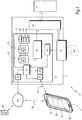
- the figure 1 represents an example of an electrical device 2 associated with an electrical installation 4.
- the installation 4 is an electricity distribution installation intended to supply electrically one or more power devices, here in an industrial or domestic environment.
- the electrical device 2 is connected to the installation 4 to control, supervise or protect all or part of the installation 4.
- the electrical device 2 is an electrical protection device, or an electrical measuring device, or an electrical switching device, in particular an electrical switching device. It can also be a supervision device or a communication device such as a network switch or an “automatic transfer switch” type device.
- the device 2 is a circuit breaker or a contactor or a disconnector suitable for interrupting the electrical supply to the installation 4 in the event of detection of an electrical fault or in response to a command from a user.
- the figure 1 also shows an electronic client terminal 6 which forms with the device 2 a system 8 and whose role is described in more detail in what follows.
- the apparatus 2 comprises at least one sub-assembly 10 which implements a function of the apparatus 2.
- the sub-assembly 10 comprises one or more electromechanical, or electrical, or magneto-electric, or electronic devices, or all other equivalent device.
- the reference “10" is used to designate the function implemented by the sub-assembly 10.
- the function 10 depends on the nature of the device 2 and, preferably, is linked to the installation 4. According to In these cases, it may be an electrical protection function of the installation 4, or a cut-off function of a electric current, or a function for measuring one or more electrical quantities. Function 10 can be controlled by a user of the device 2.
- the sub-assembly 10 is a device for interrupting an electric current connected upstream of the installation 4, so as to allow the interruption of the electrical supply to the installation 4.
- the function associated with this sub-assembly 10 corresponds to the switching of the cut-off device between electrically open and closed states.
- the function provided by the sub-assembly 10 is adapted to be logged by a user.
- a function is here called “logged” by a user when it is placed by this user in a specific state, or in a specific configuration, and when other users are prevented from modifying the state or the configuration of the sub-assembly 10. In an equivalent manner, this function is then said to be “locked” or “engaged”. Other users cannot change this feature until it has been “released”, or, in other words, “unlocked” or “disengaged”, by the user who set up logging.
- the locking of the function 10 amounts to locking the breaking device in one of its states, preferably the open state, from so as to prevent other users from switching it to another state.
- the sub-assembly 10 is a trip device for a device for cutting an electric current.
- This trip unit is parameterized by a trip curve which defines the trip unit response as a function of the measured value of an electrical quantity, such as the value of the electric current.
- the logging of the corresponding function then consists in selecting a specific trip curve different from the trip curve used during nominal operation of the device.
- This specific tripping curve sometimes known under the name of “Energy Reduction Maintenance Setting” in English, is for example defined to limit the risks in the vicinity of the circuit breaker when it trips by the occurrence of an electrical fault. when a user is working on the installation 4.
- the apparatus 2 may include several sub-assemblies 10 providing several different functions. It is therefore understood that the description given of this sub-assembly 10 can be transposed to these other embodiments.
- the apparatus 2 also comprises an on-board electronic control unit 12.
- Unit 12 is intended to control the operation of device 2.
- the unit 12 is adapted to interact with the sub-assembly 10, in particular to allow remote control and supervision of the corresponding function.
- Function 10 can thus be controlled by means of unit 12, remotely for example using terminal 6, or locally from a control panel installed on the front of appliance 2 and connected to unit 12.
- the unit 12 also makes it possible to supervise the logging of function 10, as explained below.
- the unit 12 comprises a logical calculation unit 14, such as a microprocessor or a microcontroller, a computer memory 16, a short-range communication interface 18 and a network interface 20.
- the memory 16 preferably comprises one or more non-volatile memory modules, for example of Flash or EEPROM technology or any other equivalent storage technology.
- the memory 16 comprises in particular executable instructions 17, such as machine code executable by the unit 14 and / or instructions interpretable by an interpreter executed by the unit 14, allowing in particular the implementation of the logging and release methods. of figures 2 and 3 .
- the interface 18 is suitable for establishing a short-range data exchange link 22, for example with the client terminal 6.
- the short-range data link 22 is a wired link or a point-to-point wireless link. point whose range is less than or equal to five meters.
- this is a wireless link of the “Bluetooth® Low Energy” type.
- it is a wired link, for example of the USB type.
- the network interface 20 makes it possible to establish a communication link with a remote computer network 24, such as the Internet network.
- the communication link can be wired, for example of Ethernet type, or wireless, for example of WiFi type.
- the apparatus 12 also comprises a digital locking module 30 adapted to record the function implemented by the sub-assembly 10.
- the module 30 is here implemented by the unit 12, for example in software form thanks to specific instructions implemented by the unit. unit 14, or by means of a dedicated electronic circuit of unit 12.
- the lockout implemented by the locking module 30 is called “electronic lockout”.
- module 30 when function 10 is logged by means of module 30, the latter prevents control of function 10 from unit 12, whether through a client terminal 6 connected to the unit 12 or via a control panel on the front of the device 2 or through the network interface 20.
- the device 2 is configured so that the function 10 can be locked out mechanically independently of the electronic lockout provided by the module 30.
- the device 2 comprises a mechanical locking interface 32 intended for this purpose. to receive a mechanical locking member 34, such as a padlock or a lock.
- the unit 12 advantageously comprises a measuring system 36, including for example a mechanical position sensor, which detects the state of the interface 32 and which generates a corresponding state signal, making it possible to deduce the presence or not of a mechanical locking member 34.
- the interface 32 comprises a mechanical device intended to be associated with a control member located on the front of the device 2 acting on the function 10, such as a lever or a rotary or push button or a keyboard.
- This mechanical device is configured to prevent the actuation of this control member by any user as long as the interface 32 is locked by the member 34.
- the interface 32 can be placed removably on the device 2 while being intended to be placed only when a member 34 is about to be placed and then locked, then to be removed as soon as the presence of organ 34 is no longer required.
- the measuring system 36 therefore detects the presence or, alternatively, the absence, of the interface 32.
- the information that it gives on the presence or absence of the interface 32 makes it possible to extrapolate the state of the member 34 and therefore to determine indirectly whether the function 10 is recorded mechanically or not.
- the member 34 and the interface 32 are integrated into the device and the system 36 directly measures the locked or unlocked state of the interface 32.
- the interface 32 makes it possible to offer the user the possibility of maintaining an independent mechanical locking of the digital logging functions, while allowing the latter to operate with knowledge of the state of the mechanical logging.
- the device 2 is not able to be mechanically locked. Then interface 32 and system 36 are omitted, as is component 34.
- the unit 12 comprises a generation module 40 for generating a unique digital key when a terminal client 6 requires that function 10 be logged. This key is associated with this client terminal, for example by having a unique identifier.
- Unit 12 is programmed to maintain function 10 logged as long as at least one such digital key is active, here by means of locking module 30.
- Unit 12 also includes a status indicator 44 which indicates the logged status. function 10 or not, as well as a table 48 in which are listed the active digital keys 46, that is to say the keys generated for which a logging of the function 10 is active.
- unit 40 is implemented in software by unit 12.
- unit 40 is an electronic circuit, for example a cryptographic module.
- the unit 40 generates the unique identifier by means of a predefined generation function which from data which is supplied at the input of the generation function.
- the unique identifier is at least partly generated from information exchanged with the client terminal 6 having requested the logging of the function 10, such as a connection identifier of the user who requested the logging or else of information relating to the terminal 6, such as a network address or a physical address of the terminal 6, in particular a MAC (“Media Access Control”) address.
- the unique identifier is further generated from instantaneous time information such as date and time.
- the unique identifier is also generated by the unit 12 from a random or pseudo-random element.
- the random or pseudo-random element is acquired by unit 12, for example generated by terminal 6 and then transmitted to unit 12.
- the unique identifier is a string of alphanumeric characters or numbers, for example hexadecimal.
- the length of the unique identifier is greater than or equal to 64 bits, preferably greater than or equal to 128 bits.
- the unique identifier is an identifier of the “UUID” type for “Universally Unique Identifier” as defined by the document “RFC 4122” of the “Internet Task Force” organization or by the ISO / IEC 9834 standard. 8.
- the generation function implemented by the module 40 is therefore adapted accordingly.
- the identifiers generated using such functions may not be absolutely unique and there is an extremely low probability, generally less than 10 -12 , that two identical identifiers will be generated by the same function. However, in practice this probability is so low that within the meaning of the present description, such an identifier can be considered to be unique.
- the table 48 here generically designates a data structure which resides in memory 16, of list type, or table, or vector, or database, or a tree, or any other appropriate data structure, in which each digital key active is associated with an element which identifies the client terminal 6 for which the corresponding key has been generated.
- the client terminal 6 comprises a microprocessor type calculation logic unit, a computer memory, a communication interface compatible with the interface 18 to establish a communication link 22 with the device 2, and also comprises a system of 'operation for example executed by the computing unit thanks to executable instructions stored in the memory of the client terminal 6.
- the client terminal 6 is a computer or a mobile communication device such as a telephone or a tablet.
- Application 50 is executed within the operating system.
- an application 50 installed on a client terminal 6 makes it possible for example not to require the user to have recourse to electronic equipment specifically designed to use electronic consignment. On the contrary, the user can install the application 50 on an already existing mobile communication device that he has to use elsewhere in the context of his functions. This therefore simplifies the implementation of the system 8.
- the logging and release requests are sent from the client terminal 6, which must then be close to the device 2 in order to be able to connect to the latter via the short-range link 22.
- the client terminal 6 which contains a copy of the corresponding digital key. This key is not intended to be duplicated by the user or to be copied to another client terminal. We thus find here a level of security at least equivalent to that provided by known mechanical lockout systems.
- the same terminal 6 can be used to register several functions 10 in turn on one or more devices 2 independently of each other.
- the unit 12 comprises an event logging system configured to record in an event log 42, for example recorded in a memory 16, the events relating to the logging of the function 10.
- the unit 12 is configured so that, during each operation performed by the digital lock module 30 following a request received from a client terminal 6, the control unit 12 automatically records, in the event log 42, operation tracking information including in particular an identifier of the user who is at the origin of the request, even also the date and time of the operation as well as the nature of the operation. This ensures that the use of the logging functions of the device 2 can be traced.
- the unit 12 is further programmed to send a notification such as an alert message to the client terminal (s) identified in the register 48 in the event of failure or anomaly.
- a notification such as an alert message
- the client terminal (s) identified in the register 48 in the event of failure or anomaly.
- the unit 12 is also programmed to send notifications to the user or, equivalently, to the corresponding client terminal, in response to an action by the user, for example to confirm that a logging has been done. implementation or to confirm that the lockout has been lifted.
- the unit 12 is also programmed to force the release of the lockout of the function 10, that is to say to allow a specific user to request the release of the lockout of the function 10 when even this specific user is different from the user who requested the logging of function 10 and does not have the terminal 6 nor the copy 52 of the corresponding key.
- the specific user is a system administrator and has extended security permissions.
- the administrator must first authenticate himself with the unit 12.
- the unit 12 sends a notification to the user. having requested the deposit in order to warn him of the imminent lifting of the deposit.
- a user sends a request for function 10 logging from the client terminal 6.
- the user uses the interface 56 of the application 50 to generate this request and send it to the device 2.
- the request can be preceded by a phase of pairing the terminal 6 with the device 2. , for example to establish the link 22.
- the terminal 6 can also previously receive information sent by the unit 12 indicating the logging state of the function 10, for example based on the status indicator 44, to indicate if another user has already logged in function 10, either using module 30 or, if necessary mechanically, using interface 32.
- the request is sent via the short-range link 22, which ensures that the user is close to the device 2.
- authentication of the user may be required, for example to verify whether the user is authorized to issue such a request.
- the application 50 asks the user to provide identification data, such as a predefined personal password.
- the authentication can also and / or in a complementary manner, depending on the context and the permitted use cases, be based on identification information specific to the user or to the terminal 6 or to the application 50, such as a serial number or a network address or a physical address such as a MAC address or other personalized identifier.
- identification information specific to the user or to the terminal 6 or to the application 50, such as a serial number or a network address or a physical address such as a MAC address or other personalized identifier.
- These data and / or identification information are preferably known to the unit 12, for example recorded in an access rights register stored in the memory 16 or in the authentication server 60.
- the unit 12 receives the request sent by the client terminal 6.
- the unit 12 automatically checks the authentication information sent by the terminal 6, for example from the access rights register. This verification can be done by interrogating the authentication server 60, for example to verify whether the identification data received correspond to a user authorized to send such a request.
- event log 42 is updated accordingly to record the attempted logging.
- the unit 12 automatically generates a digital key 46 comprising the unique identifier.
- the key 46 is generated here by means of the key generator 40 as described above.
- the unit 12 automatically stores the key generated in the memory 16. It advantageously updates the list 48 to associate with this key information identifying the user who sent the request.
- the unit 12 sends a copy of the key 46 to the terminal 6 which sent the request.
- the unit 12 also sends, associated with this key, information making it possible to identify the device 2, such as a serial number or a predefined identification number.
- the copy of the key is received by the application 50 by means of the link 22.
- the copy of the key received is stored in a memory space 52 of the terminal 6 and associated with the identifier of the device 2, for example a memory space 52 defined by the application 50. Once stored in space 52, the copy of the key is not intended to be copied or transmitted to another user.
- access to the memory space 52 is protected by the application 50 so as to prohibit any access to the content of this memory space 52 which would not be authorized by the application 50.
- the unit 12 authorizes the logging of function 10.
- the unit 12 activates the locking module 30 so that it logs the function 10. Once the logging is activated, the locking module 30 prevents any unexpected access to function 10 via unit 12.
- the sub-assembly 10 is a trip device parameterized by the trip curve described above, then the parameters of the trip curve can no longer be modified unexpectedly by another user. It will be understood, however, that this does not prevent the device 2 from functioning, in particular during a trip, in the sense that the mechanism of the cut-off member is then not physically blocked.
- unit 12 also updates status flag 44 to indicate that function 10 is logged.
- the event log 42 is updated accordingly during a step 112 to record the activation of the logging associated with this user.
- a confirmation is finally sent to the client terminal 6 during a step 114 to indicate that the consignment has been accepted.
- function 10 cannot be modified or altered, neither by the user who requested the logging, nor by other users.
- the function 10 remains recorded by the locking module 30 as long as there is at least one key 46 generated by the unit 12 which is stored in the memory 16 and declared in the table 48.
- a digital key 46 is active as long as it is declared in table 48.
- a user sends a request to release the logging of function 10 from the client terminal 6.
- it is the same user as the one who requested the logging and the request is sent from the same client terminal as the one having previously required consignment
- the user uses the interface 56 of the application 50 to generate this request and send it to the device 2.
- the request can be preceded by a phase of pairing the terminal 6 with the device 2. , for example to re-establish link 22 if this has been interrupted since step 100.
- Terminal 6 can also first receive information sent by unit 12 indicating the logging status of function 10, for example based on status indicator 44, to indicate whether other users have in the meantime logged function 10, either by means of module 30 or, if necessary mechanically, by means of interface 32.
- the request is sent via the short-range link 22, which ensures that the user is close to the device 2.
- control unit 12 receives the request for release.
- the control unit 12 acquires a copy of the digital key kept by the client terminal 6 which sent the request for release. For example, this key is sent by the client terminal 6 with the request for release.
- authentication of the user may be required, for example to verify whether the user is authorized to issue such a request.
- the unit 12 automatically checks the authentication information sent by the terminal 6. For example, the authentication is carried out in a manner analogous to that described with reference to l 'step 100.
- event log 42 is updated accordingly to record the release attempt.
- step 206 the unit 12 automatically compares the copy of the digital key acquired with the copy of the generated key stored in the memory 16. The function logging request is refused if the acquired key does not correspond to the stored key. For example, step 204 is then implemented.
- the control unit 12 automatically checks whether it exists, recorded in the control unit. 12, for this function, at least one other active digital key associated with another client terminal. For example, the unit 12 searches if there are other keys 46 listed in the table 48 and associated with other client terminals 6 than the one that sent the request.
- the release of the logging of function 10 by the digital locking module 30 is only authorized if the comparison shows that there is no such other active digital key associated with this function 10.
- the unit 12 authorizes the locking module 30 to release the lockout. For example, unit 12 dereferences key 46 from table 48 by deleting the corresponding entry. The unit 12 also destroys the key 46 kept in the memory 16.
- the log 42 is updated to record a follow-up of the operation of release of the logging of the function 10.
- step 210 if the comparison implemented during step 210 reveals that there is at least one other digital key 46 active for this function 10, then the logging of function 10 by digital locking module 30 is maintained during a step 216.
- an alert is sent to the client terminal 6 to inform the user at the origin of the request that his request has been accepted and that the corresponding key has been revoked, but that function 10 cannot be unlocked because there are other active keys.
- the unit 12 can send to the client terminal information on the identity of the user (s) and of their client terminal 6 which are associated with the other active keys, as a function of the information contained in the register 48.
- this information allows the application 50 to send a message to the client terminal 6 of the corresponding user.
- the sending of this information may be restricted to only certain users according to the security privileges granted to other users, for example according to personal data protection policies.
- the logging of the function is carried out in a dematerialized manner using the key 46 and a logical locking provided by the unit 12, so that the use of mechanical locking means does not is therefore no longer required.
- the device 2 can therefore have its functions 10 logged with a level of security at least equivalent to that traditionally provided by known means of mechanical logging.
- the electronic logging implemented by the unit 12 has advantages over only mechanical logging means, such as for example the traceability ensured automatically thanks to the event log 42, or the ease with which several users can log the same function independently of each other. Even in cases where mechanical locking means are used in conjunction with the unit 12, the use of the interface 32 described above in conjunction with the system 36 allows the unit 12 to have information on the device. 'state of mechanical locking.
- the steps described above for recording the function 10 can be preceded by a pre-recording phase, also called a partial recording phase.
- Such a phase is advantageous in certain applications, for example when the function 10 must be placed in a degraded operating mode, or in a maintenance mode, before the user is authorized to approach the device 2.
- step 100 the user sends a request for partial logging of function 10, preferably with the same client terminal 6 as that which will be used during step 100.
- the control unit 12 acquires the request for partial logging of the function 10.
- the client terminal 6 is connected to the control unit by a network link other than the short range communication link.
- the terminal 6 is connected to the network 24 by the link 58.
- the user is not located near the device 2, so that the client terminal 6 cannot communicate. with device 2 via the short-range link 22.
- the locking module 30 partially sets the function 10 during a step 302, so as to partially limit the use of this function 10 by the control unit 12. Once the function 10 is partially locked, the user can move closer to the device 2.
- the terminal 6 sends a request to lock the function 10 in order to implement the step 100 of the method of the figure 1 .
- the unit 12 authorizes the locking of the function 10
- the partial logging is lifted during a step 306 before being replaced by the logging of the function 10 during a step 308 analogous to the step 110.
Landscapes
- Engineering & Computer Science (AREA)
- Computer Security & Cryptography (AREA)
- Theoretical Computer Science (AREA)
- Physics & Mathematics (AREA)
- General Physics & Mathematics (AREA)
- Software Systems (AREA)
- Computer Networks & Wireless Communication (AREA)
- Computer Hardware Design (AREA)
- General Engineering & Computer Science (AREA)
- Signal Processing (AREA)
- Electromagnetism (AREA)
- Multimedia (AREA)
- Technology Law (AREA)
- Health & Medical Sciences (AREA)
- Bioethics (AREA)
- General Health & Medical Sciences (AREA)
- Lock And Its Accessories (AREA)
- Storage Device Security (AREA)
- Selective Calling Equipment (AREA)
- Telephonic Communication Services (AREA)
Claims (9)
- Verfahren zum Verriegeln einer Funktion (10) eines elektrischen Geräts (2), wobei das elektrische Gerät ein elektrisches Schutzgerät oder ein elektrisches Messgerät oder ein elektrisches Schaltgerät ist, dadurch gekennzeichnet, dass das Verfahren umfasst:a) Empfangen (100), durch eine elektronische Steuereinheit (12) des elektrischen Geräts (2), einer Anfrage, eine Funktion (10) zu verriegeln, die durch eine Unterbaugruppe des elektrischen Geräts implementiert ist, wobei die Anfrage von einem Client-Endgerät (6) gesendet wird, das mit der Steuereinheit über eine Kommunikationsverbindung (22) kurzer Reichweite verbunden ist;b) automatisches Erzeugen (106) eines digitalen Schlüssels (46), der eine eindeutige Kennung enthält, durch die Steuereinheit;c) Speichern (108) einer Kopie des erzeugten Schlüssels (46) in einem Speicher (16) der Steuereinheit (16) und Senden (108) einer weiteren Kopie (52) des erzeugten Schlüssels an das Client-Endgerät (6), das die Anfrage gesendet hat;d) Verriegeln (110) der Funktion (10) durch ein digitales Verriegelungsmodul (30) der Steuereinheit, so dass die Verwendung dieser Funktion (10) des Geräts durch die Steuereinheit verhindert wird, solange die Verriegelung aktiv ist,und dass das Verfahren außerdem die Aufhebung der zuvor mittels der Schritte a) bis d) verriegelten Funktion (10) aufweist, wobei das Verfahren umfasst:a') Empfangen (200) einer Anfrage zur Aufhebung der zuvor verriegelten Funktion (10) durch die elektronische Steuereinheit (12) des elektrischen Geräts (2), wobei die Anfrage zur Freigabe von demselben Client-Endgerät (6) gesendet wird, wobei dieses Client-Endgerät (6) mit der Steuereinheit (12) über eine Kommunikationsverbindung (22) kurzer Reichweite verbunden ist;b') in Antwort darauf Beschaffen einer Kopie des digitalen Schlüssels (52) durch die Steuereinheit (12), der von dem Client-Endgerät, das die Anfrage zur Freigabe gesendet hat, bewahrt wurde;c') Vergleichen (206) der Kopie des beschafften digitalen Schlüssels (52) mit der im Speicher (16) gespeicherten Kopie des erzeugten Schlüssels (46), wobei die Anfrage zur Aufhebung der Verriegelung der Funktion abgelehnt wird, wenn der beschaffte Schlüssel (52) nicht mit dem gespeicherten Schlüssel (46) übereinstimmt;d') automatisches Überprüfen durch die Steuereinheit (12) des Vorhandenseins, das in der Steuereinheit für diese Funktion gespeichert ist, mindestens eines anderen digitalen Schlüssels, der einem anderen Client-Endgerät zugeordnet ist, wobei diese Überprüfung nur durchgeführt wird, wenn der erfasste Schlüssel (52) als dem im Speicher (16) gespeicherten Schlüssel (46) entsprechend ermittelt wird,- wobei das Aufheben der Verriegelung der Funktion (10) durch das digitale Verriegelungsmodul (30) nur dann erlaubt ist (212), wenn kein solcher anderer digitaler Schlüssel existiert,- und die Verrieglung der Funktion (10) durch das digitale Verriegelungsmodul (30) beibehalten wird (216), wenn mindestens ein weiterer solcher digitaler Schlüssel vorhanden ist.
- Verfahren zum Verriegeln einer Funktion (10) eines elektrischen Geräts (2), wobei das elektrische Gerät ein elektrisches Schutzgerät oder ein elektrisches Messgerät oder ein elektrisches Schaltgerät ist, dadurch gekennzeichnet, dass das Verfahren umfasst:a) Empfangen (100), durch eine elektronische Steuereinheit (12) des elektrischen Geräts (2), einer Anfrage, eine Funktion (10) zu verriegeln, die durch eine Unterbaugruppe des elektrischen Geräts implementiert ist, wobei die Anfrage von einem Client-Endgerät (6) übertragen wird, das mit der Steuereinheit über eine Kommunikationsverbindung (22) kurzer Reichweite verbunden ist;b) automatisches Erzeugen (106) eines digitalen Schlüssels (46) durch die Steuereinheit, der eine eindeutige Kennung enthält, wenn das Client-Endgerät (6) zuvor als dazu autorisiert identifiziert wurde (102), die Verriegelung der Funktion zu verlangen,c) Speichern (108) einer Kopie des erzeugten Schlüssels (a6) in einem Speicher (16) der Steuereinheit (16) und Senden (108) einer weiteren Kopie (52) des erzeugten Schlüssels an das Client-Endgerät (6), das die Anfrage gesendet hat, wenn das Client-Endgerät (6) zuvor als dazu autorisiert identifiziert wurde (102), die Verriegelung der Funktion zu verlangen:d) Verriegeln (110) der Funktion (10) durch ein digitales Verriegelungsmodul (30) der Steuereinheit, so dass die Verwendung dieser Funktion (10) des Geräts durch die Steuereinheit verhindert wird, solange die Verriegelung aktiv ist, wenn das Client-Endgerät (6) zuvor als dazu autorisiert identifiziert wurde (102), die Verriegelung der Funktion zu verlangen,und dass das Verfahren außerdem die Aufhebung der zuvor mittels der Schritte a) bis d) verriegelten Funktion (10) aufweist, wobei das Verfahren umfasst:a') Empfangen (200) einer Anfrage zur Aufhebung der zuvor verriegelten Funktion (10) durch die elektronische Steuereinheit (12) des elektrischen Geräts (2), wobei die Anfrage zur Freigabe von demselben Client-Endgerät (6) gesendet wird, wobei dieses Client-Endgerät (6) mit der Steuereinheit (12) über eine Kommunikationsverbindung (22) kurzer Reichweite verbunden ist;b') in Antwort darauf Beschaffen einer Kopie des digitalen Schlüssels (52) durch die Steuereinheit ('12), der von dem Client-Endgerät, das die Anfrage zur Freigabe gesendet hat, bewahrt wurde;c') Vergleichen (206) der Kopie des beschafften digitalen Schlüssels (52) mit der im Speicher (16) gespeicherten Kopie des erzeugten Schlüssels (46), wobei die Anfrage zur Aufhebung der Verriegelung der Funktion abgelehnt wird, wenn der beschaffte Schlüssel (52) nicht mit dem gespeicherten Schlüssel (46) übereinstimmt;d') automatisches Überprüfen durch die Steuereinheit (12) des Vorhandenseins, das in der Steuereinheit für diese Funktion gespeichert ist, mindestens eines anderen digitalen Schlüssels, der einem anderen Client-Endgerät zugeordnet ist, wobei diese Überprüfung nur durchgeführt wird, wenn der erfasste Schlüssel (52) als dem im Speicher (16) gespeicherten Schlüssel (46) entsprechend ermittelt wird,- wobei das Aufheben der Verriegelung der Funktion (10) durch das digitale Verriegelungsmodul (30) nur dann erlaubt ist (212), wenn kein solcher anderer digitaler Schlüssel existiert,- und die Verrieglung der Funktion (10) durch das digitale Verriegelungsmodul (30) beibehalten wird (216), wenn mindestens ein weiterer solcher digitaler Schlüssel vorhanden ist.
- Verfahren nach Anspruch 1 oder Anspruch 2, bei dem das elektrische Gerät (2) eine mechanische Übergangsstelle (32) zur mechanischen Verriegelung aufweist, die vorgesehen ist, ein mechanisches Verriegelungselement (34) zur mechanischen Verriegelung der Funktion (10) des elektrischen Geräts unabhängig vom digitalen Verriegelungsmodul (30) der Steuereinheit (12) aufzunehmen, und bei dem die Steuereinheit (12) im Schritt d'), wenn die Aufhebung der Verriegelung der Funktion von dem digitalen Verriegelungsmodul (30) autorisiert wird, den Zustand der Übergangsstelle (32) zur mechanischen Verriegelung ermittelt, und wenn die Übergangsstelle (32) zur mechanischen Verriegelung als sich im verriegelten Zustand befindend ermittelt wird, die Steuereinheit (12) eine Benachrichtigung an das Client-Endgerät (6) sendet.
- Verfahren nach Anspruch 2 oder Anspruch 3, bei dem die Authentifizierung (102) des Client-Endgeräts (6) mittels eines entfernt liegenden Authentifizierungsservers (60) sichergestellt wird, der mit der elektronischen Steuereinheit (12) über eine Kommunikationsverbindung (24) verbunden ist, die sich von der Kommunikationsverbindung (22) kurzer Reichweite unterscheidet.
- Verfahren nach einem beliebigen der vorhergehenden Ansprüche, bei dem die Datenverbindung (22) kurzer Reichweite eine drahtgebundene Verbindung oder eine drahtlose Punkt-zu-Punkt-Verbindung ist, deren Reichweite geringer als oder gleich fünf Meter ist.
- Verfahren nach einem beliebigen der vorhergehenden Ansprüche, bei dem die Steuereinheit (12) bei jedem Vorgang, der von dem digitalen Verriegelungsmodul (30) aufgrund einer von einem Client-Endgerät (6) empfangenen Anfrage ausgeführt wird, automatisch in einem in einem Speicher (16) gespeicherten Ereignisprotokoll (42) Informationen zum Verfolgen des Vorgangs aufzeichnet, die insbesondere eine Kennung des Benutzers, der die Anforderung ausgelöst hat, aufzeichnet.
- Verfahren nach einem beliebigen der vorhergehenden Ansprüche, bei dem die eindeutige Kennung abhängig von einem zufälligen oder pseudozufälligen Elements erzeugt wird (106).
- Verfahren nach einem beliebigen der vorhergehenden Ansprüche, bei dem vor dem Schritt a):- die Steuereinheit (12) eine Anfrage zur teilweisen Verriegelung der eine Funktion (10) beschafft (300), wobei die Anfrage von einem Client-Endgerät (6) gesendet wird, das mit der Steuereinheit über eine Netzverbindung (24) unterschiedlich zur Kommunikationsverbindung kurzer Reichweite verbunden ist;- in Antwort das digitale Verriegelungsmodul (30) der Steuereinheit die Funktion (10) teilweise verriegelt (302), so dass die Verwendung dieser Funktion (10) des Geräts teilweise durch die Steuereinheit eingeschränkt wird, wobei die teilweise Verriegelung beim Schritt d) aufgehoben wird (306) und durch die Verriegelung ersetzt wird (308).
- Elektrisches Gerät (2), wobei das elektrische Gerät ein elektrisches Schutzgerät oder ein elektrisches Messgerät oder ein elektrisches Schaltgerät oder ein Überwachungs- oder Kommunikationsgerät ist, das eine Unterbaugruppe, die eine Funktion (10) implementieren kann, und eine elektronischen Steuereinheit (12) aufweist, die programmiert ist, um:a) eine Anfrage zur teilweisen Verriegelung der von der Unterbaugruppe (10) implementierten Funktion (10) zu empfangen (100), wobei die Anfrage von einem Client-Endgerät (6) gesendet wird, das mit der Steuereinheit über eine Kommunikationsverbindung (22) kurzer Reichweite verbunden ist;b) einen digitalen Schlüssel (46), der eine eindeutige Kennung enthält, automatisch zu erzeugen (106);c) eine Kopie des erzeugten Schlüssels (46) in einem Speicher (16) der Steuereinheit (16) zu speichern (108) und eine weitere Kopie (52) des erzeugten Schlüssels an das Client-Endgerät (6), das die Anfrage gesendet hat, zu übermitteln (108);d) die Funktion (10) durch ein digitales Verriegelungsmodul (30) der Steuereinheit zu verriegeln (110), so dass die Verwendung dieser Funktion (10) des Geräts durch die Steuereinheit verhindert wird, solange die Verriegelung aktiv ist,wobei die elektronische Steuereinheit (12) ferner programmiert ist, ein Verfahren zum Aufheben der Verriegelung der zuvor mittels der Merkmale a) bis d) gesperrten Funktion (10) durchzuführen, wobei dieses Verfahren umfasst:a') Empfangen (200) einer Anfrage zur Aufhebung der zuvor verriegelten Funktion (10) durch die elektronische Steuereinheit (12) des elektrischen Geräts (2), wobei die Anfrage zur Freigabe von demselben Client-Endgerät (6) gesendet wird, wobei dieses Client-Endgerät (6) mit der Steuereinheit (12) über eine Kommunikationsverbindung (22) kurzer Reichweite verbunden ist;b') in Antwort darauf Beschaffen einer Kopie des digitalen Schlüssels (52) durch die Steuereinheit (12), der von dem Client-Endgerät, das die Anfrage zur Freigabe gesendet hat, bewahrt wurde;c') Vergleichen (206) der Kopie des beschafften digitalen Schlüssels (52) mit der im Speicher (16) gespeicherten Kopie des erzeugten Schlüssels (46), wobei die Anfrage zur Aufhebung der Verriegelung der Funktion abgelehnt wird, wenn der beschaffte Schlüssel (52) nicht mit dem gespeicherten Schlüssel (46) übereinstimmt;d') automatisches Überprüfen durch die Steuereinheit (12) des Vorhandenseins, das in der Steuereinheit für diese Funktion gespeichert ist, mindestens eines anderen digitalen Schlüssels, der einem anderen Client-Endgerät zugeordnet ist, wobei diese Überprüfung nur durchgeführt wird, wenn der erfasste Schlüssel (52) als dem im Speicher (16) gespeicherten Schlüssel (46) entsprechend ermittelt wird,- wobei das Aufheben der Verriegelung der Funktion (10) durch das digitale Verriegelungsmodul (30) nur dann erlaubt ist (212), wenn kein solcher anderer digitaler Schlüssel existiert,- und die Verrieglung der Funktion (10) durch das digitale Verriegelungsmodul (30) beibehalten wird (216), wenn mindestens ein weiterer solcher digitaler Schlüssel vorhanden ist.
Applications Claiming Priority (1)
| Application Number | Priority Date | Filing Date | Title |
|---|---|---|---|
| FR1852477A FR3079343B1 (fr) | 2018-03-22 | 2018-03-22 | Procede de consignation d'une fonction d'un appareil electrique et appareil electrique mettant en oeuvre ce procede |
Publications (2)
| Publication Number | Publication Date |
|---|---|
| EP3544039A1 EP3544039A1 (de) | 2019-09-25 |
| EP3544039B1 true EP3544039B1 (de) | 2021-06-02 |
Family
ID=62017574
Family Applications (1)
| Application Number | Title | Priority Date | Filing Date |
|---|---|---|---|
| EP19164285.9A Active EP3544039B1 (de) | 2018-03-22 | 2019-03-21 | Verfahren zur verriegelung einer funktion einer elektrischen vorrichtung und eine elektrische vorrichtung zur implementierung des verfahrens |
Country Status (5)
| Country | Link |
|---|---|
| US (1) | US11146950B2 (de) |
| EP (1) | EP3544039B1 (de) |
| CN (1) | CN110298939B (de) |
| ES (1) | ES2882251T3 (de) |
| FR (1) | FR3079343B1 (de) |
Families Citing this family (6)
| Publication number | Priority date | Publication date | Assignee | Title |
|---|---|---|---|---|
| US11342728B2 (en) * | 2019-12-20 | 2022-05-24 | Eaton Intelligent Power Limited | Circuit interrupters with electronically controlled lock out tag out systems and related electrical distribution systems and methods |
| EP4468659B1 (de) | 2020-02-13 | 2026-01-21 | InterDigital Patent Holdings, Inc. | Verfahren, vorrichtung und systeme mit vehicle-to-everything (v2x)-verbesserungen zur unterstützung von fahrzeug-to-fussgänger (v2p)-kommunikation |
| US12223049B2 (en) | 2021-06-30 | 2025-02-11 | Honeywell International Inc. | Method and system for configuring a feature for an energy meter as legally important or legally non-important |
| CA3175770A1 (en) * | 2022-01-06 | 2023-07-06 | Lowe's Companies, Inc. | Benefit denial system for unlocking an electronic device |
| DE102022128789A1 (de) * | 2022-10-28 | 2024-05-08 | Maschinenfabrik Reinhausen Gmbh | Sicherer mobiler Zugang für Laststufenschaltervorrichtung |
| WO2025097226A1 (pt) * | 2023-11-07 | 2025-05-15 | Bosch Soluções Integradas Brasil Ltda | Método e conjunto de registro pessoal em um evento e método de gerenciamento de desenergização e bloqueio de um equipamento incluindo o método de registro pessoal em um evento |
Family Cites Families (25)
| Publication number | Priority date | Publication date | Assignee | Title |
|---|---|---|---|---|
| US6477021B1 (en) * | 1998-02-19 | 2002-11-05 | Square D Company | Blocking/inhibiting operation in an arc fault detection system |
| JP4090166B2 (ja) * | 1999-11-22 | 2008-05-28 | 株式会社東京アールアンドデー | 電動装置及び電動装置システム |
| ATE328319T1 (de) * | 2002-03-08 | 2006-06-15 | Revelations In Design Lp | Steuerkonsole für elektrische geräte |
| CN1682005A (zh) * | 2002-07-13 | 2005-10-12 | 罗格·烘伯 | 认证、确定、指定、定位、锁定及防盗安全系统(这里也称为锁-环dss) |
| JP2004102682A (ja) * | 2002-09-10 | 2004-04-02 | Nec Corp | 端末ロックシステムおよび端末ロック方法 |
| AU2003904317A0 (en) * | 2003-08-13 | 2003-08-28 | Securicom (Nsw) Pty Ltd | Remote entry system |
| CN1655305A (zh) * | 2004-02-12 | 2005-08-17 | 西门子公司 | 钥匙开关、用其控制电气设备功能的方法和用于其的钥匙 |
| US8020780B2 (en) * | 2007-11-30 | 2011-09-20 | Honeywell International Inc. | Thermostatic control system having a configurable lock |
| DE112011105869B4 (de) * | 2011-11-22 | 2016-10-06 | Mitsubishi Electric Corporation | Elektronisches Schlüsselsystem und schlossseitiges Endgerät und tragbares Endgerät, die in selbem verwendet werden |
| GB2515621A (en) * | 2012-01-27 | 2014-12-31 | Dunraven Finance Ltd | Control method, system and device |
| CN103541606B (zh) * | 2012-07-09 | 2016-05-04 | 山西全安新技术开发有限公司 | 一种用来锁紧螺杆的两防锁装置及其锁紧螺杆的方法 |
| EP2916887B1 (de) * | 2012-11-09 | 2016-09-07 | Fresenius Vial SAS | System zum sperren einer medizinischen vorrichtung auf einer haltestruktur |
| US20140325219A1 (en) * | 2013-04-27 | 2014-10-30 | Wanin International Co., Ltd. | Secret key management method for multi-network platform |
| US10198567B2 (en) * | 2013-09-19 | 2019-02-05 | DISH Technologies L.L.C. | Apparatus, method and article for security by pairing of devices |
| US10288675B2 (en) * | 2013-12-17 | 2019-05-14 | Eaton Intelligent Power Limited | Remote diagnostic system and method for circuit protection devices such as miniature circuit breakers |
| CN103929306B (zh) * | 2014-04-02 | 2016-04-06 | 天地融科技股份有限公司 | 智能密钥设备和智能密钥设备的信息管理方法 |
| EP2985947A1 (de) * | 2014-08-14 | 2016-02-17 | Alcatel Lucent | Verfahren zur Steuerung einer elektrischen Vorrichtung |
| CN204155797U (zh) * | 2014-11-04 | 2015-02-11 | 杭州电力设备制造有限公司 | 一种电气开关的锁定装置 |
| KR102297193B1 (ko) * | 2014-12-24 | 2021-09-02 | 삼성전자 주식회사 | 사용자 식별 기능을 가지는 전자장치 및 사용자 인증 방법 |
| US20160225562A1 (en) * | 2015-01-29 | 2016-08-04 | Unilectric, Llc | Enhanced circuit breakers and circuit breaker panels and systems and methods using the same |
| JP2016177417A (ja) * | 2015-03-19 | 2016-10-06 | Nttエレクトロニクス株式会社 | 処理装置及び遠隔管理システム |
| CN105336031B (zh) * | 2015-12-02 | 2019-10-25 | 腾讯科技(深圳)有限公司 | 一种电子锁设备及相应的控制方法 |
| CN106452845B (zh) * | 2016-09-20 | 2019-03-29 | 飞天诚信科技股份有限公司 | 一种在线解锁的实现方法及装置 |
| CN107481357A (zh) * | 2017-07-10 | 2017-12-15 | 广东工业大学 | 基于证书锁定与动态密钥的门禁安全认证方法 |
| US10553382B2 (en) * | 2017-12-15 | 2020-02-04 | Eaton Intelligent Power Limited | Bus plug including remotely operated circuit breaker and electrical system including the same |
-
2018
- 2018-03-22 FR FR1852477A patent/FR3079343B1/fr not_active Expired - Fee Related
-
2019
- 2019-03-12 CN CN201910184077.1A patent/CN110298939B/zh active Active
- 2019-03-19 US US16/357,376 patent/US11146950B2/en active Active
- 2019-03-21 EP EP19164285.9A patent/EP3544039B1/de active Active
- 2019-03-21 ES ES19164285T patent/ES2882251T3/es active Active
Non-Patent Citations (1)
| Title |
|---|
| None * |
Also Published As
| Publication number | Publication date |
|---|---|
| ES2882251T3 (es) | 2021-12-01 |
| EP3544039A1 (de) | 2019-09-25 |
| US20190297492A1 (en) | 2019-09-26 |
| CN110298939B (zh) | 2023-03-10 |
| FR3079343B1 (fr) | 2021-07-09 |
| US11146950B2 (en) | 2021-10-12 |
| FR3079343A1 (fr) | 2019-09-27 |
| CN110298939A (zh) | 2019-10-01 |
Similar Documents
| Publication | Publication Date | Title |
|---|---|---|
| EP3544039B1 (de) | Verfahren zur verriegelung einer funktion einer elektrischen vorrichtung und eine elektrische vorrichtung zur implementierung des verfahrens | |
| US8006101B2 (en) | Radio transceiver or other encryption device having secure tamper-detection module | |
| US7644290B2 (en) | System and method for seal tamper detection for intelligent electronic devices | |
| US8689350B2 (en) | Behavioral fingerprint controlled theft detection and recovery | |
| CN102413456B (zh) | 基于运营网络的用户终端防盗方法、装置和系统 | |
| EP1344375B1 (de) | Verfahren zum schutz von mobileinrichtungen vor diebstahl, entsprechende einrichtung und installation | |
| US8869133B2 (en) | Method and system for use in facilitating patch change management of industrial control systems | |
| US20130133052A1 (en) | Behavioral fingerprint device identification | |
| US20100058054A1 (en) | Mssan | |
| US9578019B2 (en) | Method and system for managing an embedded secure element eSE | |
| EP3489854B1 (de) | Gesichertes anmeldeverfahren eines entfernbaren elektrischen geräts bei seinem einbau in ein elektrisches system | |
| EP3586258B1 (de) | Segmentiertes schlüsselauthentifikationssystem | |
| EP3619634B1 (de) | Tragbares kommunikationsperipheriegerät, system zum schutz eines tragbaren endgeräts und kommunikationsverfahren | |
| EP3840324B1 (de) | Gesicherte asynchrone serienverbindung | |
| EP4173327B1 (de) | Verfahren zum schutz eines netzwerkzugangsprofils gegen klonen | |
| EP2016700A1 (de) | Endgeräteaktivierungsverfahren | |
| FR2791509A1 (fr) | Dispositif antivol pour telephone mobile | |
| EP3792807B1 (de) | Sicherungssystem einer vorrichtung | |
| EP3029599A1 (de) | Verfahren zur detektion einer trennung des hauptanschlusses eines elektronischen zahlungsterminals, entsprechendes computerprogrammprodukt, entsprechendes speichermittel und entsprechendes zahlungsterminal | |
| WO2004093019A1 (fr) | Entite electronique securisee avec compteur modifiable d'utilisations d’une donnee secrete | |
| EP2911365A1 (de) | Verfahren und System zur Sicherung von Transaktionen, die von einer Vielzahl von Diensten zwischen einem Mobilgerät eines Benutzers und einer Akzeptanzstelle angeboten werden | |
| EP2537314B1 (de) | Verfahren und gerät zur ausbreitung von sitzungsverwaltungsereignissen | |
| FR3157048A1 (fr) | Passerelle sécurisée pour gestion locale d’un ensemble hétérogène d’objets connectés | |
| JP2008112389A (ja) | クライアント端末監視方法及びシステム | |
| EP3437294A1 (de) | Fernsteuerungssystem für ein fahrzeug |
Legal Events
| Date | Code | Title | Description |
|---|---|---|---|
| PUAI | Public reference made under article 153(3) epc to a published international application that has entered the european phase |
Free format text: ORIGINAL CODE: 0009012 |
|
| STAA | Information on the status of an ep patent application or granted ep patent |
Free format text: STATUS: THE APPLICATION HAS BEEN PUBLISHED |
|
| AK | Designated contracting states |
Kind code of ref document: A1 Designated state(s): AL AT BE BG CH CY CZ DE DK EE ES FI FR GB GR HR HU IE IS IT LI LT LU LV MC MK MT NL NO PL PT RO RS SE SI SK SM TR |
|
| AX | Request for extension of the european patent |
Extension state: BA ME |
|
| STAA | Information on the status of an ep patent application or granted ep patent |
Free format text: STATUS: REQUEST FOR EXAMINATION WAS MADE |
|
| 17P | Request for examination filed |
Effective date: 20200313 |
|
| RBV | Designated contracting states (corrected) |
Designated state(s): AL AT BE BG CH CY CZ DE DK EE ES FI FR GB GR HR HU IE IS IT LI LT LU LV MC MK MT NL NO PL PT RO RS SE SI SK SM TR |
|
| RIC1 | Information provided on ipc code assigned before grant |
Ipc: H01H 27/00 20060101ALI20200730BHEP Ipc: H01H 9/20 20060101ALI20200730BHEP Ipc: H01H 9/28 20060101AFI20200730BHEP Ipc: G06F 21/10 20130101ALI20200730BHEP Ipc: H01R 13/703 20060101ALI20200730BHEP Ipc: H01H 47/00 20060101ALI20200730BHEP |
|
| STAA | Information on the status of an ep patent application or granted ep patent |
Free format text: STATUS: EXAMINATION IS IN PROGRESS |
|
| 17Q | First examination report despatched |
Effective date: 20201001 |
|
| GRAP | Despatch of communication of intention to grant a patent |
Free format text: ORIGINAL CODE: EPIDOSNIGR1 |
|
| STAA | Information on the status of an ep patent application or granted ep patent |
Free format text: STATUS: GRANT OF PATENT IS INTENDED |
|
| INTG | Intention to grant announced |
Effective date: 20210202 |
|
| GRAS | Grant fee paid |
Free format text: ORIGINAL CODE: EPIDOSNIGR3 |
|
| GRAA | (expected) grant |
Free format text: ORIGINAL CODE: 0009210 |
|
| STAA | Information on the status of an ep patent application or granted ep patent |
Free format text: STATUS: THE PATENT HAS BEEN GRANTED |
|
| REG | Reference to a national code |
Ref country code: CH Ref legal event code: EP |
|
| AK | Designated contracting states |
Kind code of ref document: B1 Designated state(s): AL AT BE BG CH CY CZ DE DK EE ES FI FR GB GR HR HU IE IS IT LI LT LU LV MC MK MT NL NO PL PT RO RS SE SI SK SM TR |
|
| REG | Reference to a national code |
Ref country code: GB Ref legal event code: FG4D Free format text: NOT ENGLISH |
|
| REG | Reference to a national code |
Ref country code: AT Ref legal event code: REF Ref document number: 1399217 Country of ref document: AT Kind code of ref document: T Effective date: 20210615 |
|
| REG | Reference to a national code |
Ref country code: IE Ref legal event code: FG4D Free format text: LANGUAGE OF EP DOCUMENT: FRENCH |
|
| REG | Reference to a national code |
Ref country code: DE Ref legal event code: R096 Ref document number: 602019004961 Country of ref document: DE |
|
| REG | Reference to a national code |
Ref country code: LT Ref legal event code: MG9D |
|
| PG25 | Lapsed in a contracting state [announced via postgrant information from national office to epo] |
Ref country code: BG Free format text: LAPSE BECAUSE OF FAILURE TO SUBMIT A TRANSLATION OF THE DESCRIPTION OR TO PAY THE FEE WITHIN THE PRESCRIBED TIME-LIMIT Effective date: 20210902 Ref country code: HR Free format text: LAPSE BECAUSE OF FAILURE TO SUBMIT A TRANSLATION OF THE DESCRIPTION OR TO PAY THE FEE WITHIN THE PRESCRIBED TIME-LIMIT Effective date: 20210602 Ref country code: LT Free format text: LAPSE BECAUSE OF FAILURE TO SUBMIT A TRANSLATION OF THE DESCRIPTION OR TO PAY THE FEE WITHIN THE PRESCRIBED TIME-LIMIT Effective date: 20210602 Ref country code: FI Free format text: LAPSE BECAUSE OF FAILURE TO SUBMIT A TRANSLATION OF THE DESCRIPTION OR TO PAY THE FEE WITHIN THE PRESCRIBED TIME-LIMIT Effective date: 20210602 |
|
| REG | Reference to a national code |
Ref country code: NL Ref legal event code: MP Effective date: 20210602 |
|
| REG | Reference to a national code |
Ref country code: AT Ref legal event code: MK05 Ref document number: 1399217 Country of ref document: AT Kind code of ref document: T Effective date: 20210602 |
|
| PG25 | Lapsed in a contracting state [announced via postgrant information from national office to epo] |
Ref country code: GR Free format text: LAPSE BECAUSE OF FAILURE TO SUBMIT A TRANSLATION OF THE DESCRIPTION OR TO PAY THE FEE WITHIN THE PRESCRIBED TIME-LIMIT Effective date: 20210903 Ref country code: SE Free format text: LAPSE BECAUSE OF FAILURE TO SUBMIT A TRANSLATION OF THE DESCRIPTION OR TO PAY THE FEE WITHIN THE PRESCRIBED TIME-LIMIT Effective date: 20210602 Ref country code: RS Free format text: LAPSE BECAUSE OF FAILURE TO SUBMIT A TRANSLATION OF THE DESCRIPTION OR TO PAY THE FEE WITHIN THE PRESCRIBED TIME-LIMIT Effective date: 20210602 Ref country code: LV Free format text: LAPSE BECAUSE OF FAILURE TO SUBMIT A TRANSLATION OF THE DESCRIPTION OR TO PAY THE FEE WITHIN THE PRESCRIBED TIME-LIMIT Effective date: 20210602 Ref country code: NO Free format text: LAPSE BECAUSE OF FAILURE TO SUBMIT A TRANSLATION OF THE DESCRIPTION OR TO PAY THE FEE WITHIN THE PRESCRIBED TIME-LIMIT Effective date: 20210902 Ref country code: PL Free format text: LAPSE BECAUSE OF FAILURE TO SUBMIT A TRANSLATION OF THE DESCRIPTION OR TO PAY THE FEE WITHIN THE PRESCRIBED TIME-LIMIT Effective date: 20210602 |
|
| REG | Reference to a national code |
Ref country code: ES Ref legal event code: FG2A Ref document number: 2882251 Country of ref document: ES Kind code of ref document: T3 Effective date: 20211201 |
|
| PG25 | Lapsed in a contracting state [announced via postgrant information from national office to epo] |
Ref country code: NL Free format text: LAPSE BECAUSE OF FAILURE TO SUBMIT A TRANSLATION OF THE DESCRIPTION OR TO PAY THE FEE WITHIN THE PRESCRIBED TIME-LIMIT Effective date: 20210602 Ref country code: RO Free format text: LAPSE BECAUSE OF FAILURE TO SUBMIT A TRANSLATION OF THE DESCRIPTION OR TO PAY THE FEE WITHIN THE PRESCRIBED TIME-LIMIT Effective date: 20210602 Ref country code: PT Free format text: LAPSE BECAUSE OF FAILURE TO SUBMIT A TRANSLATION OF THE DESCRIPTION OR TO PAY THE FEE WITHIN THE PRESCRIBED TIME-LIMIT Effective date: 20211004 Ref country code: SM Free format text: LAPSE BECAUSE OF FAILURE TO SUBMIT A TRANSLATION OF THE DESCRIPTION OR TO PAY THE FEE WITHIN THE PRESCRIBED TIME-LIMIT Effective date: 20210602 Ref country code: CZ Free format text: LAPSE BECAUSE OF FAILURE TO SUBMIT A TRANSLATION OF THE DESCRIPTION OR TO PAY THE FEE WITHIN THE PRESCRIBED TIME-LIMIT Effective date: 20210602 Ref country code: AT Free format text: LAPSE BECAUSE OF FAILURE TO SUBMIT A TRANSLATION OF THE DESCRIPTION OR TO PAY THE FEE WITHIN THE PRESCRIBED TIME-LIMIT Effective date: 20210602 Ref country code: SK Free format text: LAPSE BECAUSE OF FAILURE TO SUBMIT A TRANSLATION OF THE DESCRIPTION OR TO PAY THE FEE WITHIN THE PRESCRIBED TIME-LIMIT Effective date: 20210602 Ref country code: EE Free format text: LAPSE BECAUSE OF FAILURE TO SUBMIT A TRANSLATION OF THE DESCRIPTION OR TO PAY THE FEE WITHIN THE PRESCRIBED TIME-LIMIT Effective date: 20210602 |
|
| REG | Reference to a national code |
Ref country code: DE Ref legal event code: R097 Ref document number: 602019004961 Country of ref document: DE |
|
| PLBE | No opposition filed within time limit |
Free format text: ORIGINAL CODE: 0009261 |
|
| STAA | Information on the status of an ep patent application or granted ep patent |
Free format text: STATUS: NO OPPOSITION FILED WITHIN TIME LIMIT |
|
| PG25 | Lapsed in a contracting state [announced via postgrant information from national office to epo] |
Ref country code: DK Free format text: LAPSE BECAUSE OF FAILURE TO SUBMIT A TRANSLATION OF THE DESCRIPTION OR TO PAY THE FEE WITHIN THE PRESCRIBED TIME-LIMIT Effective date: 20210602 |
|
| 26N | No opposition filed |
Effective date: 20220303 |
|
| PG25 | Lapsed in a contracting state [announced via postgrant information from national office to epo] |
Ref country code: AL Free format text: LAPSE BECAUSE OF FAILURE TO SUBMIT A TRANSLATION OF THE DESCRIPTION OR TO PAY THE FEE WITHIN THE PRESCRIBED TIME-LIMIT Effective date: 20210602 |
|
| PG25 | Lapsed in a contracting state [announced via postgrant information from national office to epo] |
Ref country code: MC Free format text: LAPSE BECAUSE OF FAILURE TO SUBMIT A TRANSLATION OF THE DESCRIPTION OR TO PAY THE FEE WITHIN THE PRESCRIBED TIME-LIMIT Effective date: 20210602 |
|
| REG | Reference to a national code |
Ref country code: CH Ref legal event code: PL |
|
| REG | Reference to a national code |
Ref country code: BE Ref legal event code: MM Effective date: 20220331 |
|
| PG25 | Lapsed in a contracting state [announced via postgrant information from national office to epo] |
Ref country code: LU Free format text: LAPSE BECAUSE OF NON-PAYMENT OF DUE FEES Effective date: 20220321 Ref country code: LI Free format text: LAPSE BECAUSE OF NON-PAYMENT OF DUE FEES Effective date: 20220331 Ref country code: IE Free format text: LAPSE BECAUSE OF NON-PAYMENT OF DUE FEES Effective date: 20220321 Ref country code: CH Free format text: LAPSE BECAUSE OF NON-PAYMENT OF DUE FEES Effective date: 20220331 |
|
| PG25 | Lapsed in a contracting state [announced via postgrant information from national office to epo] |
Ref country code: BE Free format text: LAPSE BECAUSE OF NON-PAYMENT OF DUE FEES Effective date: 20220331 |
|
| PG25 | Lapsed in a contracting state [announced via postgrant information from national office to epo] |
Ref country code: MK Free format text: LAPSE BECAUSE OF FAILURE TO SUBMIT A TRANSLATION OF THE DESCRIPTION OR TO PAY THE FEE WITHIN THE PRESCRIBED TIME-LIMIT Effective date: 20210602 Ref country code: CY Free format text: LAPSE BECAUSE OF FAILURE TO SUBMIT A TRANSLATION OF THE DESCRIPTION OR TO PAY THE FEE WITHIN THE PRESCRIBED TIME-LIMIT Effective date: 20210602 |
|
| PG25 | Lapsed in a contracting state [announced via postgrant information from national office to epo] |
Ref country code: HU Free format text: LAPSE BECAUSE OF FAILURE TO SUBMIT A TRANSLATION OF THE DESCRIPTION OR TO PAY THE FEE WITHIN THE PRESCRIBED TIME-LIMIT; INVALID AB INITIO Effective date: 20190321 |
|
| PG25 | Lapsed in a contracting state [announced via postgrant information from national office to epo] |
Ref country code: MT Free format text: LAPSE BECAUSE OF FAILURE TO SUBMIT A TRANSLATION OF THE DESCRIPTION OR TO PAY THE FEE WITHIN THE PRESCRIBED TIME-LIMIT Effective date: 20210602 |
|
| PGFP | Annual fee paid to national office [announced via postgrant information from national office to epo] |
Ref country code: IT Payment date: 20250321 Year of fee payment: 7 |
|
| PGFP | Annual fee paid to national office [announced via postgrant information from national office to epo] |
Ref country code: ES Payment date: 20250417 Year of fee payment: 7 |
|
| PG25 | Lapsed in a contracting state [announced via postgrant information from national office to epo] |
Ref country code: TR Free format text: LAPSE BECAUSE OF FAILURE TO SUBMIT A TRANSLATION OF THE DESCRIPTION OR TO PAY THE FEE WITHIN THE PRESCRIBED TIME-LIMIT Effective date: 20210602 |
|
| PGFP | Annual fee paid to national office [announced via postgrant information from national office to epo] |
Ref country code: GB Payment date: 20260324 Year of fee payment: 8 |
|
| PGFP | Annual fee paid to national office [announced via postgrant information from national office to epo] |
Ref country code: DE Payment date: 20260326 Year of fee payment: 8 |
|
| PGFP | Annual fee paid to national office [announced via postgrant information from national office to epo] |
Ref country code: FR Payment date: 20260323 Year of fee payment: 8 |