EP3543817A1 - Mitigation of resonance in a transport refrigeration unit - Google Patents
Mitigation of resonance in a transport refrigeration unit Download PDFInfo
- Publication number
- EP3543817A1 EP3543817A1 EP19163874.1A EP19163874A EP3543817A1 EP 3543817 A1 EP3543817 A1 EP 3543817A1 EP 19163874 A EP19163874 A EP 19163874A EP 3543817 A1 EP3543817 A1 EP 3543817A1
- Authority
- EP
- European Patent Office
- Prior art keywords
- tru
- data
- controller
- components
- operational baseline
- Prior art date
- Legal status (The legal status is an assumption and is not a legal conclusion. Google has not performed a legal analysis and makes no representation as to the accuracy of the status listed.)
- Granted
Links
Images


Classifications
-
- G—PHYSICS
- G05—CONTROLLING; REGULATING
- G05D—SYSTEMS FOR CONTROLLING OR REGULATING NON-ELECTRIC VARIABLES
- G05D19/00—Control of mechanical oscillations, e.g. of amplitude, of frequency, of phase
- G05D19/02—Control of mechanical oscillations, e.g. of amplitude, of frequency, of phase characterised by the use of electric means
-
- G—PHYSICS
- G01—MEASURING; TESTING
- G01M—TESTING STATIC OR DYNAMIC BALANCE OF MACHINES OR STRUCTURES; TESTING OF STRUCTURES OR APPARATUS, NOT OTHERWISE PROVIDED FOR
- G01M7/00—Vibration-testing of structures; Shock-testing of structures
- G01M7/02—Vibration-testing by means of a shake table
- G01M7/022—Vibration control arrangements, e.g. for generating random vibrations
-
- B—PERFORMING OPERATIONS; TRANSPORTING
- B60—VEHICLES IN GENERAL
- B60H—ARRANGEMENTS OF HEATING, COOLING, VENTILATING OR OTHER AIR-TREATING DEVICES SPECIALLY ADAPTED FOR PASSENGER OR GOODS SPACES OF VEHICLES
- B60H1/00—Heating, cooling or ventilating devices
- B60H1/00357—Air-conditioning arrangements specially adapted for particular vehicles
- B60H1/00364—Air-conditioning arrangements specially adapted for particular vehicles for caravans or trailers
-
- B—PERFORMING OPERATIONS; TRANSPORTING
- B60—VEHICLES IN GENERAL
- B60H—ARRANGEMENTS OF HEATING, COOLING, VENTILATING OR OTHER AIR-TREATING DEVICES SPECIALLY ADAPTED FOR PASSENGER OR GOODS SPACES OF VEHICLES
- B60H1/00—Heating, cooling or ventilating devices
- B60H1/00507—Details, e.g. mounting arrangements, desaeration devices
-
- B—PERFORMING OPERATIONS; TRANSPORTING
- B60—VEHICLES IN GENERAL
- B60H—ARRANGEMENTS OF HEATING, COOLING, VENTILATING OR OTHER AIR-TREATING DEVICES SPECIALLY ADAPTED FOR PASSENGER OR GOODS SPACES OF VEHICLES
- B60H1/00—Heating, cooling or ventilating devices
- B60H1/00642—Control systems or circuits; Control members or indication devices for heating, cooling or ventilating devices
- B60H1/00735—Control systems or circuits characterised by their input, i.e. by the detection, measurement or calculation of particular conditions, e.g. signal treatment, dynamic models
-
- B—PERFORMING OPERATIONS; TRANSPORTING
- B60—VEHICLES IN GENERAL
- B60H—ARRANGEMENTS OF HEATING, COOLING, VENTILATING OR OTHER AIR-TREATING DEVICES SPECIALLY ADAPTED FOR PASSENGER OR GOODS SPACES OF VEHICLES
- B60H1/00—Heating, cooling or ventilating devices
- B60H1/32—Cooling devices
-
- B—PERFORMING OPERATIONS; TRANSPORTING
- B60—VEHICLES IN GENERAL
- B60H—ARRANGEMENTS OF HEATING, COOLING, VENTILATING OR OTHER AIR-TREATING DEVICES SPECIALLY ADAPTED FOR PASSENGER OR GOODS SPACES OF VEHICLES
- B60H1/00—Heating, cooling or ventilating devices
- B60H1/32—Cooling devices
- B60H1/3204—Cooling devices using compression
- B60H1/3205—Control means therefor
-
- F—MECHANICAL ENGINEERING; LIGHTING; HEATING; WEAPONS; BLASTING
- F25—REFRIGERATION OR COOLING; COMBINED HEATING AND REFRIGERATION SYSTEMS; HEAT PUMP SYSTEMS; MANUFACTURE OR STORAGE OF ICE; LIQUEFACTION SOLIDIFICATION OF GASES
- F25B—REFRIGERATION MACHINES, PLANTS OR SYSTEMS; COMBINED HEATING AND REFRIGERATION SYSTEMS; HEAT PUMP SYSTEMS
- F25B49/00—Arrangement or mounting of control or safety devices
-
- G—PHYSICS
- G01—MEASURING; TESTING
- G01H—MEASUREMENT OF MECHANICAL VIBRATIONS OR ULTRASONIC, SONIC OR INFRASONIC WAVES
- G01H13/00—Measuring resonant frequency
-
- G—PHYSICS
- G01—MEASURING; TESTING
- G01M—TESTING STATIC OR DYNAMIC BALANCE OF MACHINES OR STRUCTURES; TESTING OF STRUCTURES OR APPARATUS, NOT OTHERWISE PROVIDED FOR
- G01M7/00—Vibration-testing of structures; Shock-testing of structures
- G01M7/02—Vibration-testing by means of a shake table
- G01M7/025—Measuring arrangements
-
- G—PHYSICS
- G06—COMPUTING OR CALCULATING; COUNTING
- G06F—ELECTRIC DIGITAL DATA PROCESSING
- G06F7/00—Methods or arrangements for processing data by operating upon the order or content of the data handled
- G06F7/02—Comparing digital values
- G06F7/026—Magnitude comparison, i.e. determining the relative order of operands based on their numerical value, e.g. window comparator
-
- B—PERFORMING OPERATIONS; TRANSPORTING
- B60—VEHICLES IN GENERAL
- B60H—ARRANGEMENTS OF HEATING, COOLING, VENTILATING OR OTHER AIR-TREATING DEVICES SPECIALLY ADAPTED FOR PASSENGER OR GOODS SPACES OF VEHICLES
- B60H1/00—Heating, cooling or ventilating devices
- B60H1/32—Cooling devices
- B60H1/3204—Cooling devices using compression
- B60H1/3232—Cooling devices using compression particularly adapted for load transporting vehicles
-
- B—PERFORMING OPERATIONS; TRANSPORTING
- B60—VEHICLES IN GENERAL
- B60H—ARRANGEMENTS OF HEATING, COOLING, VENTILATING OR OTHER AIR-TREATING DEVICES SPECIALLY ADAPTED FOR PASSENGER OR GOODS SPACES OF VEHICLES
- B60H1/00—Heating, cooling or ventilating devices
- B60H1/32—Cooling devices
- B60H2001/3269—Cooling devices output of a control signal
- B60H2001/327—Cooling devices output of a control signal related to a compressing unit
- B60H2001/3272—Cooling devices output of a control signal related to a compressing unit to control the revolving speed of a compressor
-
- G—PHYSICS
- G08—SIGNALLING
- G08B—SIGNALLING SYSTEMS, e.g. PERSONAL CALLING SYSTEMS; ORDER TELEGRAPHS; ALARM SYSTEMS
- G08B17/00—Fire alarms; Alarms responsive to explosion
- G08B17/06—Electric actuation of the alarm, e.g. using a thermally-operated switch
Definitions
- Exemplary embodiments pertain to the art of vibration avoidance and more specifically to vibration avoidance in a transport refrigeration unit.
- Refrigerated trailers may include a transport refrigeration unit (TRU) to provide proper conditioning for cargo shipped in the trailer.
- TRU transport refrigeration unit
- the TRU includes a TRU engine that may propagate a spectrum of vibration energy levels onto various components such as TRU engine mounts, components mounted to the TRU, etc.
- the TRU engine operates at speeds corresponding to one or more resonance frequencies for the components, which may magnify the energy and the effect of the vibrations on the components and lead to component failure.
- TRU and related components may be designed to avoid vibrations at targeted TRU speeds. There may be potential, however, for antiquated or unanticipated configuration variabilities and/or vibrational unbalances in components and products that may result in unpredicted resonance in the TRU engine, TRU engine mounts, related parts or mounted components. Moreover, if TRU engine mount deterioration occurs in the field, such deterioration may result in excessive motion during resonance and may result in TRU engine or TRU component failure.
- a system for dynamically mitigating resonance in a transport refrigeration unit (TRU) during a mission comprising: a TRU controller configured for operating a TRU engine during the mission according to an operational baseline, and while operating the TRU engine, contemporaneously performing steps comprising: obtaining a first set of data that comprises real time measurements from one or more accelerometers installed in the TRU; converting the real measurements to a second set of data that comprises real time shock and vibration data; processing the second set of data in a control loop to determine an updated operational baseline that avoids resonance detected in the first set of data; and operating the TRU engine according to the updated operational baseline.
- a TRU controller configured for operating a TRU engine during the mission according to an operational baseline, and while operating the TRU engine, contemporaneously performing steps comprising: obtaining a first set of data that comprises real time measurements from one or more accelerometers installed in the TRU; converting the real measurements to a second set of data that comprises real time shock and vibration data; processing the second set of data in a control loop to determine
- the operational baseline and updated operational baseline each identifies a frequency of operation for the TRU engine.
- the TRU controller forwards one or more of the first set of data, the second set of data and the updated operational baseline to a fleet central server.
- the fleet central server receives the one or more of the first set of data, the second set of data and the updated operational baseline and develops one or more of preventative maintenance prognostics and updated design and testing profiles.
- the TRU comprises TRU components and the TRU controller compares the second set of data to a first set of reference data indicative of an acceptable vibrational range for the TRU components.
- the TRU controller filters, from the second set of data, data indicative of real time shock and vibration data that is within the acceptable vibrational range for the TRU components and the TRU controller processes the filtered second set of data in the control loop to determine the updated operational baseline that avoids resonance detected in the first set of data.
- the TRU comprises TRU components and the TRU controller compares the second set of data to a second set of reference data indicative of a failure of one or more of the TRU components.
- the TRU controller triggers an alarm when determining that the second set of data is indicative of failure of one or more of the TRU components.
- the TRU controller compares the second set of data to a third set of reference data indicative of pending vibrations.
- the TRU controller determines an updated operational baseline that avoids resonance induced by pending vibrations.
- TRU transport refrigeration unit
- the operational environment of one embodiment includes a trailer 100 having therein a transport refrigeration unit (TRU) 104.
- the TRU includes a TRU engine 108 and a plurality of TRU components.
- the plurality of TRU components includes for example a plurality of TRU engine mounts including a first TRU engine mount 112 and a second TRU engine mount 116.
- the plurality of TRU components may include a plurality of mounted parts including a first mounted part 120 and a second mounted part 124.
- the plurality of mounted parts may be of the typical kind found in a TRU, including movable and/or rotating parts that provide necessary services for items transported in the trailer 100.
- the TRU engine may be a variable speed engine capable of being dynamically controlled by a TRU controller 128.
- the TRU controller may be onboard the TRU engine or may be a separate component in the TRU.
- the TRU controller may communicate with and be programmed by a fleet central server 132. Such communications may occur via cellular or other wireless network 136 or wired network as structured in the fleet headquarters 140. Communications may be directly with one or more cellular devices 138 in possession of an operator of the TRU or with maintenance personnel for diagnostic or other purposes.
- the disclosed system may include one or more accelerometers including a first accelerometer 144 mounted within the TRU.
- a second accelerometer 146 may be disposed on the TRU engine and/or on one or more of the TRU components.
- the accelerometers may be dynamically controlled by the controller 128 or by another controller onboard the TRU.
- the accelerometers may be capable of measuring and feeding first data 148, representing real time data, to the TRU controller 128.
- the TRU controller 128 may process the first data 148 to obtain second data 152, representing real time shock and vibration data experienced by the TRU components.
- the second data can be fed to a control loop 156 that may be executed by the TRU controller.
- Output 160 from the control loop 156 may be used drive the TRU engine at a frequency that is continuously fine-tuned to avoid resonance.
- a process for mitigating resonance in a TRU.
- the process includes the TRU controller performing step S100 of controlling the TRU engine according to initial baseline parameters. Such parameters include running the TRU engine at a preset operational frequency.
- the TRU controller then preforms step S104 of recording first data representing real time accelerometer measurements.
- the TRU controller processes the first data to obtain second data representing real time shock and vibrations experienced by the TRU components.
- the TRU controller may compare the second data with first reference data indicative of an acceptable range of vibrations, as discussed below.
- the TRU controller may compare the second data with second reference data indicative of component failure, as also discussed below.
- the TRU controller may compare the second data with a third reference data indicative of pending further shock, as also discussed in detail below.
- the TRU controller may perform any combination of steps S109, S110 and S111.
- the determination at each of steps S109, S110, and S111 may be "yes", “no” or "complete”. The response of "complete” may be after responding "yes" to one of these steps and then executing further associated steps, discussed in detail below.
- step S112 the second data is processed by the TRU controller, through the control loop, to obtain updated baseline parameters for controlling the TRU engine.
- the control loop calculations are designed to run the TRU engine at frequencies that dampen and/or avoid frequencies causing resonance in the TRU components. In one embodiment the control loop may provide for incremental increasing or decreasing of TRU engine speeds.
- the updated baseline parameters are fed to the TRU engine, and the system then cycles back to step S100.
- the TRU controller may continue from step S116 to step S120 illustrated in FIG. 3 , wherein the TRU controller forwards compiled data to the fleet central server, including a historical profile of updated TRU operational baselines which have been accumulated over a period of time.
- the fleet central server may process the compiled data to develop preventative maintenance prognostics.
- the compiled data may be processed by the fleet central server to generate updated design and testing profiles. From such processes, initial baselines and control loops may account for expected vibration profiles developed through testing of nominal systems in the laboratory and/or field.
- the TRU controller may first perform step S132 of comparing with first reference data representing acceptable vibrational levels for the TRU components. Expected vibration profiles for the TRU components may be obtained through testing of nominal TRU systems in a laboratory and/or in normal operation. If the determination at step S132 is "yes", then the TRU controller may cycle back to step S100 without processing the data in the control loop. If the determination at step S132 is "no" then the TRU controller may perform step S136 of processing the second data to remove acceptable vibrational data. Then the TRU controller may continue to step S109 as indicated above.
- the TRU controller at step S148 may compare the second data to second reference data containing vibration patterns indicative of near term or actual failure of specific TRU components, such as TRU mounts. When vibration patterns are not indicative of specific component failure, the TRU controller may return to step S110.
- the vibration patterns are indicative of specific component failure, at step S152 the TRU controller may actively send an alarm to the central server or the cellular device. The alarm may indicate, for example, that the engine mounts are beginning to wear and need to be replaced, or that a TRU component has failed. This may avoid eventual failure of the mounts, and potential cascading failures. With alarms sent, the TRU controller may advance to step S110. It is to be appreciated that outside of catastrophic failures TRU components may be fixed or replaced at a convenient point during a mission, not necessarily upon sounding of an alarm, which may be at any point during a mission.
- the TRU controller at step S140 may compare real time data to third reference data containing vibration patterns which are indicative of pending further shock. If the determination is “no” then the TRU controller may continue to step S112. If the determination is "yes” then the TRU controller at step S144 may employ prognostic logic that anticipates shock induced excitations and takes preventative measures to prevent resonant failure modes while in transport. Such active controls may avoid a vibration related failure.
- the disclosed embodiments may be performed contemporaneously to provide for proactive identification of excessive vibrations due to resonance driven by TRU engine speeds, and for automatic corrective action before a system or component failure occurs. Additionally the disclosed embodiments may provide smoother engine operations and improved product reliability. Using accelerometers with control algorithms for variable speed TRU engines, system reliability may be improved resulting in lowered operating and/or warranty costs. Also, relatively rapid responses by the TRU controller may avoid damage to the TRU following, for example, a vehicular accident involving the trailer, or an unusual vehicular positioning of the trailer, that may impart impulses, stresses and strains on the TRU. In addition, for example, proactively identifying worn components such as TRU mounts enables changing of such components before such causes (a) excessive unit vibrations, and/or (b) failure of other components in the system, such as an exhaust system, refrigeration pipes, etc.
Landscapes
- Physics & Mathematics (AREA)
- Engineering & Computer Science (AREA)
- Thermal Sciences (AREA)
- Mechanical Engineering (AREA)
- General Physics & Mathematics (AREA)
- Theoretical Computer Science (AREA)
- General Engineering & Computer Science (AREA)
- Automation & Control Theory (AREA)
- Mathematical Optimization (AREA)
- Pure & Applied Mathematics (AREA)
- Mathematical Analysis (AREA)
- Computational Mathematics (AREA)
- Combined Controls Of Internal Combustion Engines (AREA)
- Vibration Prevention Devices (AREA)
Abstract
Description
- Exemplary embodiments pertain to the art of vibration avoidance and more specifically to vibration avoidance in a transport refrigeration unit.
- Refrigerated trailers may include a transport refrigeration unit (TRU) to provide proper conditioning for cargo shipped in the trailer. The TRU includes a TRU engine that may propagate a spectrum of vibration energy levels onto various components such as TRU engine mounts, components mounted to the TRU, etc. In some cases, the TRU engine operates at speeds corresponding to one or more resonance frequencies for the components, which may magnify the energy and the effect of the vibrations on the components and lead to component failure.
- It may be possible to design the TRU and related components to avoid vibrations at targeted TRU speeds. There may be potential, however, for antiquated or unanticipated configuration variabilities and/or vibrational unbalances in components and products that may result in unpredicted resonance in the TRU engine, TRU engine mounts, related parts or mounted components. Moreover, if TRU engine mount deterioration occurs in the field, such deterioration may result in excessive motion during resonance and may result in TRU engine or TRU component failure.
- Disclosed is a system for dynamically mitigating resonance in a transport refrigeration unit (TRU) during a mission, comprising: a TRU controller configured for operating a TRU engine during the mission according to an operational baseline, and while operating the TRU engine, contemporaneously performing steps comprising: obtaining a first set of data that comprises real time measurements from one or more accelerometers installed in the TRU; converting the real measurements to a second set of data that comprises real time shock and vibration data; processing the second set of data in a control loop to determine an updated operational baseline that avoids resonance detected in the first set of data; and operating the TRU engine according to the updated operational baseline.
- In addition to a combination of one or more of the above disclosed features and steps, or as an alternate, the operational baseline and updated operational baseline each identifies a frequency of operation for the TRU engine.
- In addition to a combination of one or more of the above disclosed features and steps, or as an alternate, the TRU controller forwards one or more of the first set of data, the second set of data and the updated operational baseline to a fleet central server.
- In addition to a combination of one or more of the above disclosed features and steps, or as an alternate, the fleet central server receives the one or more of the first set of data, the second set of data and the updated operational baseline and develops one or more of preventative maintenance prognostics and updated design and testing profiles.
- In addition to a combination of one or more of the above disclosed features and steps, or as an alternate, the TRU comprises TRU components and the TRU controller compares the second set of data to a first set of reference data indicative of an acceptable vibrational range for the TRU components.
- In addition to a combination of one or more of the above disclosed features and steps, or as an alternate, the TRU controller filters, from the second set of data, data indicative of real time shock and vibration data that is within the acceptable vibrational range for the TRU components and the TRU controller processes the filtered second set of data in the control loop to determine the updated operational baseline that avoids resonance detected in the first set of data.
- In addition to a combination of one or more of the above disclosed features and steps, or as an alternate, the TRU comprises TRU components and the TRU controller compares the second set of data to a second set of reference data indicative of a failure of one or more of the TRU components.
- In addition to a combination of one or more of the above disclosed features and steps, or as an alternate, the TRU controller triggers an alarm when determining that the second set of data is indicative of failure of one or more of the TRU components.
- In addition to a combination of one or more of the above disclosed features and steps, or as an alternate, the TRU controller compares the second set of data to a third set of reference data indicative of pending vibrations.
- In addition to a combination of one or more of the above disclosed features and steps, or as an alternate, the TRU controller determines an updated operational baseline that avoids resonance induced by pending vibrations.
- Further disclosed is a method for dynamically mitigating resonance in a transport refrigeration unit (TRU) during a mission, comprising one or more of the above disclosed features and/or steps.
- The following descriptions should not be considered limiting in any way. With reference to the accompanying drawings, like elements are numbered alike:
-
FIG. 1 is an illustration of components according to an embodiment; -
FIG. 2 is a flowchart according to an embodiment; -
FIG. 3 is a flowchart according to an embodiment; -
FIG. 4 is a flowchart according to an embodiment; -
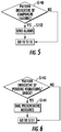
FIG. 5 is a flowchart according to an embodiment; and -
FIG. 6 is a flowchart according to an embodiment; - A detailed description of one or more embodiments of the disclosed apparatus and method are presented herein by way of exemplification and not limitation with reference to the Figures.
- Turning to
FIG. 1 , the operational environment of one embodiment includes atrailer 100 having therein a transport refrigeration unit (TRU) 104. The TRU includes aTRU engine 108 and a plurality of TRU components. The plurality of TRU components includes for example a plurality of TRU engine mounts including a firstTRU engine mount 112 and a secondTRU engine mount 116. The plurality of TRU components may include a plurality of mounted parts including a first mountedpart 120 and a second mountedpart 124. The plurality of mounted parts may be of the typical kind found in a TRU, including movable and/or rotating parts that provide necessary services for items transported in thetrailer 100. - The TRU engine may be a variable speed engine capable of being dynamically controlled by a
TRU controller 128. The TRU controller may be onboard the TRU engine or may be a separate component in the TRU. The TRU controller may communicate with and be programmed by a fleetcentral server 132. Such communications may occur via cellular or otherwireless network 136 or wired network as structured in thefleet headquarters 140. Communications may be directly with one or morecellular devices 138 in possession of an operator of the TRU or with maintenance personnel for diagnostic or other purposes. - According to an embodiment, the disclosed system may include one or more accelerometers including a
first accelerometer 144 mounted within the TRU. Asecond accelerometer 146 may be disposed on the TRU engine and/or on one or more of the TRU components. The accelerometers may be dynamically controlled by thecontroller 128 or by another controller onboard the TRU. The accelerometers may be capable of measuring and feedingfirst data 148, representing real time data, to theTRU controller 128. With the addition of accelerometers and feedback to theTRU controller 128, theTRU controller 128 may process thefirst data 148 to obtainsecond data 152, representing real time shock and vibration data experienced by the TRU components. The second data can be fed to acontrol loop 156 that may be executed by the TRU controller.Output 160 from thecontrol loop 156 may be used drive the TRU engine at a frequency that is continuously fine-tuned to avoid resonance. - Turning to
FIG. 2 , a process is disclosed for mitigating resonance in a TRU. The process includes the TRU controller performing step S100 of controlling the TRU engine according to initial baseline parameters. Such parameters include running the TRU engine at a preset operational frequency. The TRU controller then preforms step S104 of recording first data representing real time accelerometer measurements. At step S108 the TRU controller processes the first data to obtain second data representing real time shock and vibrations experienced by the TRU components. - At step S109 the TRU controller may compare the second data with first reference data indicative of an acceptable range of vibrations, as discussed below. At step S110 the TRU controller may compare the second data with second reference data indicative of component failure, as also discussed below. At step S111 the TRU controller may compare the second data with a third reference data indicative of pending further shock, as also discussed in detail below. As illustrated, the TRU controller may perform any combination of steps S109, S110 and S111. The determination at each of steps S109, S110, and S111 may be "yes", "no" or "complete". The response of "complete" may be after responding "yes" to one of these steps and then executing further associated steps, discussed in detail below.
- When the determination at each of steps S109, S110 and S111 is "no" or "complete", at step S112 the second data is processed by the TRU controller, through the control loop, to obtain updated baseline parameters for controlling the TRU engine. As indicated, the control loop calculations are designed to run the TRU engine at frequencies that dampen and/or avoid frequencies causing resonance in the TRU components. In one embodiment the control loop may provide for incremental increasing or decreasing of TRU engine speeds. At step S116, the updated baseline parameters are fed to the TRU engine, and the system then cycles back to step S100.
- In one embodiment, the TRU controller may continue from step S116 to step S120 illustrated in
FIG. 3 , wherein the TRU controller forwards compiled data to the fleet central server, including a historical profile of updated TRU operational baselines which have been accumulated over a period of time. At step S124 the fleet central server may process the compiled data to develop preventative maintenance prognostics. At step S128 the compiled data may be processed by the fleet central server to generate updated design and testing profiles. From such processes, initial baselines and control loops may account for expected vibration profiles developed through testing of nominal systems in the laboratory and/or field. - Turning to
FIGS. 1 ,2 and4 , upon selecting "yes" at step S109, the TRU controller may first perform step S132 of comparing with first reference data representing acceptable vibrational levels for the TRU components. Expected vibration profiles for the TRU components may be obtained through testing of nominal TRU systems in a laboratory and/or in normal operation. If the determination at step S132 is "yes", then the TRU controller may cycle back to step S100 without processing the data in the control loop. If the determination at step S132 is "no" then the TRU controller may perform step S136 of processing the second data to remove acceptable vibrational data. Then the TRU controller may continue to step S109 as indicated above. - Turning to
FIGS. 1 ,2 and5 , upon selecting "yes" at step S110, the TRU controller at step S148 may compare the second data to second reference data containing vibration patterns indicative of near term or actual failure of specific TRU components, such as TRU mounts. When vibration patterns are not indicative of specific component failure, the TRU controller may return to step S110. When the vibration patterns are indicative of specific component failure, at step S152 the TRU controller may actively send an alarm to the central server or the cellular device. The alarm may indicate, for example, that the engine mounts are beginning to wear and need to be replaced, or that a TRU component has failed. This may avoid eventual failure of the mounts, and potential cascading failures. With alarms sent, the TRU controller may advance to step S110. It is to be appreciated that outside of catastrophic failures TRU components may be fixed or replaced at a convenient point during a mission, not necessarily upon sounding of an alarm, which may be at any point during a mission. - Turning to
FIGS. 1 ,2 and6 , upon selecting "yes" at step S111, the TRU controller at step S140 may compare real time data to third reference data containing vibration patterns which are indicative of pending further shock. If the determination is "no" then the TRU controller may continue to step S112. If the determination is "yes" then the TRU controller at step S144 may employ prognostic logic that anticipates shock induced excitations and takes preventative measures to prevent resonant failure modes while in transport. Such active controls may avoid a vibration related failure. - The disclosed embodiments may be performed contemporaneously to provide for proactive identification of excessive vibrations due to resonance driven by TRU engine speeds, and for automatic corrective action before a system or component failure occurs. Additionally the disclosed embodiments may provide smoother engine operations and improved product reliability. Using accelerometers with control algorithms for variable speed TRU engines, system reliability may be improved resulting in lowered operating and/or warranty costs. Also, relatively rapid responses by the TRU controller may avoid damage to the TRU following, for example, a vehicular accident involving the trailer, or an unusual vehicular positioning of the trailer, that may impart impulses, stresses and strains on the TRU. In addition, for example, proactively identifying worn components such as TRU mounts enables changing of such components before such causes (a) excessive unit vibrations, and/or (b) failure of other components in the system, such as an exhaust system, refrigeration pipes, etc.
- The term "about" is intended to include the degree of error associated with measurement of the particular quantity based upon the equipment available at the time of filing the application. The terminology used herein is for the purpose of describing particular embodiments only and is not intended to be limiting of the present invention. As used herein, the singular forms "a", "an" and "the" are intended to include the plural forms as well, unless the context clearly indicates otherwise. It will be further understood that the terms "comprises" and/or "comprising," when used in this specification, specify the presence of stated features, integers, steps, operations, elements, and/or components, but do not preclude the presence or addition of one or more other features, integers, steps, operations, element components, and/or groups thereof.
- While the present disclosure has been described with reference to an exemplary embodiment or embodiments, it will be understood by those skilled in the art that various changes may be made and equivalents may be substituted for elements thereof without departing from the scope of the present invention. In addition, many modifications may be made to adapt a particular situation or material to the teachings of the present invention without departing from the scope thereof. Therefore, it is intended that the present invention not be limited to the particular embodiment disclosed as the best mode contemplated for carrying out this present disclosure, but that the present invention will include all embodiments falling within the scope of the claims.
Claims (15)
- A system for dynamically mitigating resonance in a transport refrigeration unit (TRU) (104) during a mission, comprising:
a TRU controller (128) configured for operating a TRU engine (108) during the mission according to an operational baseline, and while operating the TRU engine, contemporaneously performing steps comprising:obtaining a first set of data (148) that comprises real time measurements from one or more accelerometers (144,146) installed in the TRU;converting the real measurements to a second set of data (152) that comprises real time shock and vibration data;processing the second set of data in a control loop (156) to determine an updated operational baseline that avoids resonance detected in the first set of data; andoperating the TRU engine according to the updated operational baseline. - The system of claim 1 wherein the operational baseline and updated operational baseline each identifies a frequency of operation for the TRU engine.
- The system of claim 1 or 2 wherein the TRU controller (128) forwards one or more of the first set of data (148), the second set of data (152) and the updated operational baseline to a fleet central server (132).
- The system of claim 3, wherein the fleet central server (132) receives the one or more of the first set of data (148), the second set of data (152) and the updated operational baseline and develops one or more of preventative maintenance prognostics and updated design and testing profiles.
- The system of any preceding claim wherein the TRU (104) comprises TRU components and the TRU controller (128) compares the second set of data (152) to a first set of reference data indicative of an acceptable vibrational range for the TRU components.
- The system of claim 5 wherein the TRU controller (128) filters, from the second set of data (152), data indicative of real time shock and vibration data that is within the acceptable vibrational range for the TRU components and the TRU controller (128) processes the filtered second set of data in the control loop (156) to determine the updated operational baseline that avoids resonance detected in the first set of data.
- The system of any preceding claim wherein the TRU comprises TRU components and the TRU controller (128) compares the second set of data (152) to a second set of reference data indicative of a failure of one or more of the TRU components,
optionally wherein the TRU controller (128) triggers an alarm when determining that the second set of data (152) is indicative of failure of one or more of the TRU components. - The system of any preceding claim wherein the TRU controller (128) compares the second set of data (152) to a third set of reference data indicative of pending vibrations,
optionally wherein the TRU controller (128) determines an updated operational baseline that avoids resonance induced by pending vibrations. - A method for dynamically mitigating resonance in a transport refrigeration unit (TRU) (104) during a mission, comprising:
a TRU controller (128) operating a TRU engine during the mission according to an operational baseline, and while operating the TRU engine, contemporaneously performing steps comprising:obtaining a first set of data (148) that comprises real time measurements from one or more accelerometers installed in the TRU;converting the real measurements to a second set of data (152) that comprises real time shock and vibration data;processing the second set of data in a control loop (156) to determine an updated operational baseline that avoids resonance detected in the first set of data; andoperating the TRU engine according to the updated operational baseline. - The method of claim 9 wherein the operational baseline and updated operational baseline each identifies a frequency of operation for the TRU engine.
- The method of claim 9 or 10 wherein the TRU controller (128) forwards one or more of the first set of data (148), the second set of data (152) and the updated operational baseline to a fleet central server (132),
optionally wherein the fleet central server (132) receives the one or more of the first set of data (148), the second set of data (152) and the updated operational baseline and develops one or more of preventative maintenance prognostics and updated design and testing profiles. - The method of claim 9, 10 or 11 wherein the TRU (104) comprises TRU components and the TRU controller (128) compares the second set of data (152) to a first set of reference data indicative of an acceptable vibrational range for the TRU components.
- The method of claim 12 wherein the TRU controller (128) filters, from the second set of data (152), data indicative of real time shock and vibration data that is within the acceptable vibrational range for the TRU components and the TRU controller (128) processes the filtered second set of data in the control loop (156) to determine the updated operational baseline that avoids resonance detected in the first set of data (148).
- The method of any of claims 9 to 13 wherein the TRU comprises TRU components and the TRU controller (128) compares the second set of data (152) to a second set of reference data indicative of a failure of one or more of the TRU components,
optionally wherein the TRU controller (128) triggers an alarm when determining that the second set of data (152) is indicative of failure of one or more of the TRU components. - The method of any of claims 9 to 14 wherein the TRU controller (128) compares the second set of data (152) to a third set of reference data indicative of pending vibrations,
optionally wherein the TRU controller (128) determines an updated operational baseline that avoids resonance induced by pending vibrations.
Applications Claiming Priority (1)
| Application Number | Priority Date | Filing Date | Title |
|---|---|---|---|
| US201862644822P | 2018-03-19 | 2018-03-19 |
Publications (2)
| Publication Number | Publication Date |
|---|---|
| EP3543817A1 true EP3543817A1 (en) | 2019-09-25 |
| EP3543817B1 EP3543817B1 (en) | 2020-11-04 |
Family
ID=65904020
Family Applications (1)
| Application Number | Title | Priority Date | Filing Date |
|---|---|---|---|
| EP19163874.1A Not-in-force EP3543817B1 (en) | 2018-03-19 | 2019-03-19 | Mitigation of resonance in a transport refrigeration unit |
Country Status (3)
| Country | Link |
|---|---|
| US (1) | US11474000B2 (en) |
| EP (1) | EP3543817B1 (en) |
| CN (1) | CN110281730B (en) |
Cited By (1)
| Publication number | Priority date | Publication date | Assignee | Title |
|---|---|---|---|---|
| CN114537078A (en) * | 2020-11-25 | 2022-05-27 | 开利公司 | Method and device for determining the influence on a temperature control unit |
Families Citing this family (3)
| Publication number | Priority date | Publication date | Assignee | Title |
|---|---|---|---|---|
| CN113352842B (en) * | 2021-05-24 | 2023-04-18 | 青岛海尔空调器有限总公司 | Vehicle-mounted air conditioner, control method thereof and computer-readable storage medium |
| JP2023017224A (en) * | 2021-07-26 | 2023-02-07 | トヨタ自動車株式会社 | vehicle air conditioner |
| CN116572704B (en) * | 2023-05-31 | 2025-10-10 | 奇瑞汽车股份有限公司 | A method for reducing noise in automobile HVAC system |
Citations (2)
| Publication number | Priority date | Publication date | Assignee | Title |
|---|---|---|---|---|
| WO2017172701A1 (en) * | 2016-03-28 | 2017-10-05 | Carrier Corporation | Automated diagnostics for transport refrigeration units |
| US20180061207A1 (en) * | 2016-09-01 | 2018-03-01 | Locus Solutions, Llc | Systems and methods for monitoring vibrations during transportation of goods |
Family Cites Families (27)
| Publication number | Priority date | Publication date | Assignee | Title |
|---|---|---|---|---|
| US4012942A (en) | 1976-05-17 | 1977-03-22 | General Motors Corporation | Borderline spark knock detector |
| US4608650A (en) | 1983-08-09 | 1986-08-26 | Becton Dickinson And Company | Imbalance measuring system and method |
| GB8710998D0 (en) | 1987-05-08 | 1987-06-10 | Btr Plc | Vehicle engine suspension systems |
| KR19980030279A (en) | 1996-10-29 | 1998-07-25 | 김영귀 | Vehicle active engine mount system |
| US6754571B2 (en) | 2001-07-30 | 2004-06-22 | Delphi Technologies, Inc. | Control of magnetorheological engine mount |
| US6589135B2 (en) | 2001-08-21 | 2003-07-08 | Deere & Company | System and method for reducing vehicle bouncing |
| KR100444043B1 (en) | 2001-10-29 | 2004-08-11 | 현대자동차주식회사 | Engine mount using electro-magnetic force |
| KR100436573B1 (en) * | 2001-12-24 | 2004-06-19 | 최 현 | Automatic vibration and sound quality evaluation system |
| US7133761B2 (en) | 2003-06-30 | 2006-11-07 | Westport Research Inc. | Method and apparatus for controlling an internal combustion engine using accelerometers |
| GB0410324D0 (en) | 2004-05-08 | 2004-06-09 | Ford Global Tech Llc | Improvements relating to engines |
| US20060198744A1 (en) * | 2005-03-03 | 2006-09-07 | Carrier Corporation | Skipping frequencies for variable speed controls |
| US7547980B2 (en) | 2006-02-10 | 2009-06-16 | Roger Harrison | Power generating unit on semi-trailer for energy recovery and storage |
| US7895003B2 (en) * | 2007-10-05 | 2011-02-22 | Emerson Climate Technologies, Inc. | Vibration protection in a variable speed compressor |
| KR20090130604A (en) | 2008-06-16 | 2009-12-24 | 현대자동차주식회사 | Automotive Engine Vibration Damping Device |
| US8571829B2 (en) | 2008-07-11 | 2013-10-29 | University Of Washington Through Its Center For Commercialization | Detecting objects in shipping containers by vibration spectral analysis |
| US9890982B2 (en) * | 2008-08-07 | 2018-02-13 | Carrier Corporation | Discrete frequency operation for unit capacity control |
| US8041500B2 (en) | 2010-04-08 | 2011-10-18 | Ford Global Technologies, Llc | Reformate control via accelerometer |
| KR20120024301A (en) | 2010-09-06 | 2012-03-14 | 콘티넨탈 오토모티브 시스템 주식회사 | Method for monitoring engine mount, and apparatus applied to the same |
| US9669904B2 (en) * | 2011-05-12 | 2017-06-06 | Unmanned Innovations, Inc. | Systems and methods for multi-mode unmanned vehicle mission planning and control |
| US8692689B2 (en) | 2011-05-12 | 2014-04-08 | Qualcomm Incorporated | Vehicle context awareness by detecting engine RPM using a motion sensor |
| US9976565B2 (en) * | 2011-06-30 | 2018-05-22 | Carrier Corporation | Compressor surge detection |
| FI126724B (en) | 2011-09-29 | 2017-04-28 | Conexbird Oy | container security |
| TWI577953B (en) * | 2011-11-30 | 2017-04-11 | 強生控制科技公司 | System and method for reducing noise in a refrigeration system |
| BR112014027963A2 (en) * | 2012-05-09 | 2017-06-27 | Thermo King Corp | remote monitoring of a transport cooling system |
| CN104684757B (en) * | 2012-10-01 | 2017-04-12 | 冷王公司 | Periodic system diagnostic of a transport refrigeration system |
| US9841354B2 (en) | 2014-04-28 | 2017-12-12 | Hong Kong Baptist University | Diagnosis of internal combustion engine performance |
| US20170158026A1 (en) * | 2014-07-15 | 2017-06-08 | Carrier Corporation | Transport refrigeration unit and method of driving a compressor |
-
2019
- 2019-03-18 CN CN201910203907.0A patent/CN110281730B/en active Active
- 2019-03-19 EP EP19163874.1A patent/EP3543817B1/en not_active Not-in-force
- 2019-03-19 US US16/357,939 patent/US11474000B2/en active Active
Patent Citations (2)
| Publication number | Priority date | Publication date | Assignee | Title |
|---|---|---|---|---|
| WO2017172701A1 (en) * | 2016-03-28 | 2017-10-05 | Carrier Corporation | Automated diagnostics for transport refrigeration units |
| US20180061207A1 (en) * | 2016-09-01 | 2018-03-01 | Locus Solutions, Llc | Systems and methods for monitoring vibrations during transportation of goods |
Cited By (3)
| Publication number | Priority date | Publication date | Assignee | Title |
|---|---|---|---|---|
| CN114537078A (en) * | 2020-11-25 | 2022-05-27 | 开利公司 | Method and device for determining the influence on a temperature control unit |
| EP4008575A1 (en) * | 2020-11-25 | 2022-06-08 | Carrier Corporation | A method and an apparatus to determining an impact on a temperature-controlled unit |
| US11724566B2 (en) | 2020-11-25 | 2023-08-15 | Carrier Corporation | Method and an apparatus to determining an impact on a temperature-controlled unit |
Also Published As
| Publication number | Publication date |
|---|---|
| US11474000B2 (en) | 2022-10-18 |
| CN110281730B (en) | 2024-11-26 |
| US20190285510A1 (en) | 2019-09-19 |
| EP3543817B1 (en) | 2020-11-04 |
| CN110281730A (en) | 2019-09-27 |
Similar Documents
| Publication | Publication Date | Title |
|---|---|---|
| US11474000B2 (en) | Mitigation of resonance in a transport refrigeration unit | |
| US10928783B2 (en) | Analysis device and analysis system for ranking predictor performance for determining acceptability of an object to be produced | |
| CN107122830B (en) | Analysis apparatus and analysis system | |
| EP2959347B1 (en) | A method and an apparatus for predicting the condition of a machine or a component of the machine | |
| CA2921259C (en) | Method of evaluating a part | |
| EP4015250B1 (en) | System and method for real-time health prediction of tires | |
| US11287805B2 (en) | Servo driver and state change detecting method | |
| US20170178015A1 (en) | Maintenance timing prediction system and maintenance timing prediction device | |
| US20190129372A1 (en) | Abnormality determination system, data transmitter-receptor, motor controller, and method for determining abnormality | |
| JP6722372B2 (en) | Machine tool monitoring and predictive control system with tool recognition function | |
| KR102246005B1 (en) | Real-time sensing data processing system for smart factory and processing method the same | |
| US10955837B2 (en) | Method and system for error detection and monitoring for an electronically closed-loop or open-loop controlled machine part | |
| CN110677218B (en) | Data collection system, data collection method, and control device | |
| US20210400069A1 (en) | Information processing apparatus | |
| JP5283362B2 (en) | Passenger conveyor diagnostic equipment | |
| EP3417262B1 (en) | Predictive monitoring system and method | |
| EP4572131A1 (en) | Motor fault detection and remaining useful life prediction | |
| CN121742438A (en) | Asset condition monitoring method using automatic anomaly detection | |
| JP2023530858A (en) | Method for predictive maintenance of automatic machinery for manufacturing or packaging consumer products | |
| US20240231289A1 (en) | Systems and methods for monitoring and training a manufacturing system | |
| EP4184459A1 (en) | Maintenance system | |
| US20240198473A1 (en) | Vibration detection device | |
| JP2007112565A (en) | Drive system diagnostic device | |
| Kumar et al. | A Study on Reliability Analysis of Haul Trucks | |
| JP6459686B2 (en) | Control device, system, and library program |
Legal Events
| Date | Code | Title | Description |
|---|---|---|---|
| PUAI | Public reference made under article 153(3) epc to a published international application that has entered the european phase |
Free format text: ORIGINAL CODE: 0009012 |
|
| STAA | Information on the status of an ep patent application or granted ep patent |
Free format text: STATUS: THE APPLICATION HAS BEEN PUBLISHED |
|
| AK | Designated contracting states |
Kind code of ref document: A1 Designated state(s): AL AT BE BG CH CY CZ DE DK EE ES FI FR GB GR HR HU IE IS IT LI LT LU LV MC MK MT NL NO PL PT RO RS SE SI SK SM TR |
|
| AX | Request for extension of the european patent |
Extension state: BA ME |
|
| STAA | Information on the status of an ep patent application or granted ep patent |
Free format text: STATUS: REQUEST FOR EXAMINATION WAS MADE |
|
| 17P | Request for examination filed |
Effective date: 20200320 |
|
| RBV | Designated contracting states (corrected) |
Designated state(s): AL AT BE BG CH CY CZ DE DK EE ES FI FR GB GR HR HU IE IS IT LI LT LU LV MC MK MT NL NO PL PT RO RS SE SI SK SM TR |
|
| RIC1 | Information provided on ipc code assigned before grant |
Ipc: G05D 19/02 20060101AFI20200527BHEP Ipc: B60H 1/32 20060101ALI20200527BHEP Ipc: B60H 1/00 20060101ALI20200527BHEP |
|
| GRAP | Despatch of communication of intention to grant a patent |
Free format text: ORIGINAL CODE: EPIDOSNIGR1 |
|
| STAA | Information on the status of an ep patent application or granted ep patent |
Free format text: STATUS: GRANT OF PATENT IS INTENDED |
|
| INTG | Intention to grant announced |
Effective date: 20200703 |
|
| GRAS | Grant fee paid |
Free format text: ORIGINAL CODE: EPIDOSNIGR3 |
|
| GRAA | (expected) grant |
Free format text: ORIGINAL CODE: 0009210 |
|
| STAA | Information on the status of an ep patent application or granted ep patent |
Free format text: STATUS: THE PATENT HAS BEEN GRANTED |
|
| AK | Designated contracting states |
Kind code of ref document: B1 Designated state(s): AL AT BE BG CH CY CZ DE DK EE ES FI FR GB GR HR HU IE IS IT LI LT LU LV MC MK MT NL NO PL PT RO RS SE SI SK SM TR |
|
| REG | Reference to a national code |
Ref country code: GB Ref legal event code: FG4D |
|
| REG | Reference to a national code |
Ref country code: CH Ref legal event code: EP |
|
| REG | Reference to a national code |
Ref country code: AT Ref legal event code: REF Ref document number: 1331622 Country of ref document: AT Kind code of ref document: T Effective date: 20201115 |
|
| REG | Reference to a national code |
Ref country code: IE Ref legal event code: FG4D |
|
| REG | Reference to a national code |
Ref country code: DE Ref legal event code: R096 Ref document number: 602019001157 Country of ref document: DE |
|
| REG | Reference to a national code |
Ref country code: NL Ref legal event code: FP |
|
| REG | Reference to a national code |
Ref country code: AT Ref legal event code: MK05 Ref document number: 1331622 Country of ref document: AT Kind code of ref document: T Effective date: 20201104 |
|
| PG25 | Lapsed in a contracting state [announced via postgrant information from national office to epo] |
Ref country code: FI Free format text: LAPSE BECAUSE OF FAILURE TO SUBMIT A TRANSLATION OF THE DESCRIPTION OR TO PAY THE FEE WITHIN THE PRESCRIBED TIME-LIMIT Effective date: 20201104 Ref country code: RS Free format text: LAPSE BECAUSE OF FAILURE TO SUBMIT A TRANSLATION OF THE DESCRIPTION OR TO PAY THE FEE WITHIN THE PRESCRIBED TIME-LIMIT Effective date: 20201104 Ref country code: PT Free format text: LAPSE BECAUSE OF FAILURE TO SUBMIT A TRANSLATION OF THE DESCRIPTION OR TO PAY THE FEE WITHIN THE PRESCRIBED TIME-LIMIT Effective date: 20210304 Ref country code: GR Free format text: LAPSE BECAUSE OF FAILURE TO SUBMIT A TRANSLATION OF THE DESCRIPTION OR TO PAY THE FEE WITHIN THE PRESCRIBED TIME-LIMIT Effective date: 20210205 Ref country code: NO Free format text: LAPSE BECAUSE OF FAILURE TO SUBMIT A TRANSLATION OF THE DESCRIPTION OR TO PAY THE FEE WITHIN THE PRESCRIBED TIME-LIMIT Effective date: 20210204 |
|
| PG25 | Lapsed in a contracting state [announced via postgrant information from national office to epo] |
Ref country code: BG Free format text: LAPSE BECAUSE OF FAILURE TO SUBMIT A TRANSLATION OF THE DESCRIPTION OR TO PAY THE FEE WITHIN THE PRESCRIBED TIME-LIMIT Effective date: 20210204 Ref country code: SE Free format text: LAPSE BECAUSE OF FAILURE TO SUBMIT A TRANSLATION OF THE DESCRIPTION OR TO PAY THE FEE WITHIN THE PRESCRIBED TIME-LIMIT Effective date: 20201104 Ref country code: LV Free format text: LAPSE BECAUSE OF FAILURE TO SUBMIT A TRANSLATION OF THE DESCRIPTION OR TO PAY THE FEE WITHIN THE PRESCRIBED TIME-LIMIT Effective date: 20201104 Ref country code: IS Free format text: LAPSE BECAUSE OF FAILURE TO SUBMIT A TRANSLATION OF THE DESCRIPTION OR TO PAY THE FEE WITHIN THE PRESCRIBED TIME-LIMIT Effective date: 20210304 Ref country code: PL Free format text: LAPSE BECAUSE OF FAILURE TO SUBMIT A TRANSLATION OF THE DESCRIPTION OR TO PAY THE FEE WITHIN THE PRESCRIBED TIME-LIMIT Effective date: 20201104 Ref country code: ES Free format text: LAPSE BECAUSE OF FAILURE TO SUBMIT A TRANSLATION OF THE DESCRIPTION OR TO PAY THE FEE WITHIN THE PRESCRIBED TIME-LIMIT Effective date: 20201104 Ref country code: AT Free format text: LAPSE BECAUSE OF FAILURE TO SUBMIT A TRANSLATION OF THE DESCRIPTION OR TO PAY THE FEE WITHIN THE PRESCRIBED TIME-LIMIT Effective date: 20201104 |
|
| REG | Reference to a national code |
Ref country code: LT Ref legal event code: MG9D |
|
| PG25 | Lapsed in a contracting state [announced via postgrant information from national office to epo] |
Ref country code: HR Free format text: LAPSE BECAUSE OF FAILURE TO SUBMIT A TRANSLATION OF THE DESCRIPTION OR TO PAY THE FEE WITHIN THE PRESCRIBED TIME-LIMIT Effective date: 20201104 |
|
| PG25 | Lapsed in a contracting state [announced via postgrant information from national office to epo] |
Ref country code: SM Free format text: LAPSE BECAUSE OF FAILURE TO SUBMIT A TRANSLATION OF THE DESCRIPTION OR TO PAY THE FEE WITHIN THE PRESCRIBED TIME-LIMIT Effective date: 20201104 Ref country code: SK Free format text: LAPSE BECAUSE OF FAILURE TO SUBMIT A TRANSLATION OF THE DESCRIPTION OR TO PAY THE FEE WITHIN THE PRESCRIBED TIME-LIMIT Effective date: 20201104 Ref country code: EE Free format text: LAPSE BECAUSE OF FAILURE TO SUBMIT A TRANSLATION OF THE DESCRIPTION OR TO PAY THE FEE WITHIN THE PRESCRIBED TIME-LIMIT Effective date: 20201104 Ref country code: CZ Free format text: LAPSE BECAUSE OF FAILURE TO SUBMIT A TRANSLATION OF THE DESCRIPTION OR TO PAY THE FEE WITHIN THE PRESCRIBED TIME-LIMIT Effective date: 20201104 Ref country code: RO Free format text: LAPSE BECAUSE OF FAILURE TO SUBMIT A TRANSLATION OF THE DESCRIPTION OR TO PAY THE FEE WITHIN THE PRESCRIBED TIME-LIMIT Effective date: 20201104 Ref country code: LT Free format text: LAPSE BECAUSE OF FAILURE TO SUBMIT A TRANSLATION OF THE DESCRIPTION OR TO PAY THE FEE WITHIN THE PRESCRIBED TIME-LIMIT Effective date: 20201104 |
|
| REG | Reference to a national code |
Ref country code: DE Ref legal event code: R097 Ref document number: 602019001157 Country of ref document: DE |
|
| PG25 | Lapsed in a contracting state [announced via postgrant information from national office to epo] |
Ref country code: DK Free format text: LAPSE BECAUSE OF FAILURE TO SUBMIT A TRANSLATION OF THE DESCRIPTION OR TO PAY THE FEE WITHIN THE PRESCRIBED TIME-LIMIT Effective date: 20201104 |
|
| PLBE | No opposition filed within time limit |
Free format text: ORIGINAL CODE: 0009261 |
|
| STAA | Information on the status of an ep patent application or granted ep patent |
Free format text: STATUS: NO OPPOSITION FILED WITHIN TIME LIMIT |
|
| 26N | No opposition filed |
Effective date: 20210805 |
|
| PG25 | Lapsed in a contracting state [announced via postgrant information from national office to epo] |
Ref country code: AL Free format text: LAPSE BECAUSE OF FAILURE TO SUBMIT A TRANSLATION OF THE DESCRIPTION OR TO PAY THE FEE WITHIN THE PRESCRIBED TIME-LIMIT Effective date: 20201104 Ref country code: MC Free format text: LAPSE BECAUSE OF FAILURE TO SUBMIT A TRANSLATION OF THE DESCRIPTION OR TO PAY THE FEE WITHIN THE PRESCRIBED TIME-LIMIT Effective date: 20201104 Ref country code: IT Free format text: LAPSE BECAUSE OF FAILURE TO SUBMIT A TRANSLATION OF THE DESCRIPTION OR TO PAY THE FEE WITHIN THE PRESCRIBED TIME-LIMIT Effective date: 20201104 |
|
| PG25 | Lapsed in a contracting state [announced via postgrant information from national office to epo] |
Ref country code: SI Free format text: LAPSE BECAUSE OF FAILURE TO SUBMIT A TRANSLATION OF THE DESCRIPTION OR TO PAY THE FEE WITHIN THE PRESCRIBED TIME-LIMIT Effective date: 20201104 |
|
| REG | Reference to a national code |
Ref country code: BE Ref legal event code: MM Effective date: 20210331 |
|
| PG25 | Lapsed in a contracting state [announced via postgrant information from national office to epo] |
Ref country code: LU Free format text: LAPSE BECAUSE OF NON-PAYMENT OF DUE FEES Effective date: 20210319 Ref country code: IE Free format text: LAPSE BECAUSE OF NON-PAYMENT OF DUE FEES Effective date: 20210319 |
|
| PGFP | Annual fee paid to national office [announced via postgrant information from national office to epo] |
Ref country code: DE Payment date: 20220217 Year of fee payment: 4 |
|
| PG25 | Lapsed in a contracting state [announced via postgrant information from national office to epo] |
Ref country code: IS Free format text: LAPSE BECAUSE OF FAILURE TO SUBMIT A TRANSLATION OF THE DESCRIPTION OR TO PAY THE FEE WITHIN THE PRESCRIBED TIME-LIMIT Effective date: 20210304 |
|
| PGFP | Annual fee paid to national office [announced via postgrant information from national office to epo] |
Ref country code: FR Payment date: 20220221 Year of fee payment: 4 Ref country code: NL Payment date: 20220217 Year of fee payment: 4 |
|
| PG25 | Lapsed in a contracting state [announced via postgrant information from national office to epo] |
Ref country code: BE Free format text: LAPSE BECAUSE OF NON-PAYMENT OF DUE FEES Effective date: 20210331 |
|
| REG | Reference to a national code |
Ref country code: CH Ref legal event code: PL |
|
| PG25 | Lapsed in a contracting state [announced via postgrant information from national office to epo] |
Ref country code: LI Free format text: LAPSE BECAUSE OF NON-PAYMENT OF DUE FEES Effective date: 20220331 Ref country code: CH Free format text: LAPSE BECAUSE OF NON-PAYMENT OF DUE FEES Effective date: 20220331 |
|
| PG25 | Lapsed in a contracting state [announced via postgrant information from national office to epo] |
Ref country code: CY Free format text: LAPSE BECAUSE OF FAILURE TO SUBMIT A TRANSLATION OF THE DESCRIPTION OR TO PAY THE FEE WITHIN THE PRESCRIBED TIME-LIMIT Effective date: 20201104 |
|
| PG25 | Lapsed in a contracting state [announced via postgrant information from national office to epo] |
Ref country code: HU Free format text: LAPSE BECAUSE OF FAILURE TO SUBMIT A TRANSLATION OF THE DESCRIPTION OR TO PAY THE FEE WITHIN THE PRESCRIBED TIME-LIMIT; INVALID AB INITIO Effective date: 20190319 |
|
| REG | Reference to a national code |
Ref country code: DE Ref legal event code: R119 Ref document number: 602019001157 Country of ref document: DE |
|
| REG | Reference to a national code |
Ref country code: NL Ref legal event code: MM Effective date: 20230401 |
|
| GBPC | Gb: european patent ceased through non-payment of renewal fee |
Effective date: 20230319 |
|
| PG25 | Lapsed in a contracting state [announced via postgrant information from national office to epo] |
Ref country code: NL Free format text: LAPSE BECAUSE OF NON-PAYMENT OF DUE FEES Effective date: 20230401 |
|
| PG25 | Lapsed in a contracting state [announced via postgrant information from national office to epo] |
Ref country code: GB Free format text: LAPSE BECAUSE OF NON-PAYMENT OF DUE FEES Effective date: 20230319 |
|
| PG25 | Lapsed in a contracting state [announced via postgrant information from national office to epo] |
Ref country code: FR Free format text: LAPSE BECAUSE OF NON-PAYMENT OF DUE FEES Effective date: 20230331 Ref country code: DE Free format text: LAPSE BECAUSE OF NON-PAYMENT OF DUE FEES Effective date: 20231003 Ref country code: GB Free format text: LAPSE BECAUSE OF NON-PAYMENT OF DUE FEES Effective date: 20230319 |
|
| PG25 | Lapsed in a contracting state [announced via postgrant information from national office to epo] |
Ref country code: MK Free format text: LAPSE BECAUSE OF FAILURE TO SUBMIT A TRANSLATION OF THE DESCRIPTION OR TO PAY THE FEE WITHIN THE PRESCRIBED TIME-LIMIT Effective date: 20201104 |
|
| PG25 | Lapsed in a contracting state [announced via postgrant information from national office to epo] |
Ref country code: MT Free format text: LAPSE BECAUSE OF FAILURE TO SUBMIT A TRANSLATION OF THE DESCRIPTION OR TO PAY THE FEE WITHIN THE PRESCRIBED TIME-LIMIT Effective date: 20201104 |
|
| PG25 | Lapsed in a contracting state [announced via postgrant information from national office to epo] |
Ref country code: TR Free format text: LAPSE BECAUSE OF FAILURE TO SUBMIT A TRANSLATION OF THE DESCRIPTION OR TO PAY THE FEE WITHIN THE PRESCRIBED TIME-LIMIT Effective date: 20201104 |