EP3543765A1 - Display member, head-up display device, and jig - Google Patents
Display member, head-up display device, and jig Download PDFInfo
- Publication number
- EP3543765A1 EP3543765A1 EP17871662.7A EP17871662A EP3543765A1 EP 3543765 A1 EP3543765 A1 EP 3543765A1 EP 17871662 A EP17871662 A EP 17871662A EP 3543765 A1 EP3543765 A1 EP 3543765A1
- Authority
- EP
- European Patent Office
- Prior art keywords
- jig
- combiner
- engaging
- held
- display member
- Prior art date
- Legal status (The legal status is an assumption and is not a legal conclusion. Google has not performed a legal analysis and makes no representation as to the accuracy of the status listed.)
- Withdrawn
Links
Images



Classifications
-
- B—PERFORMING OPERATIONS; TRANSPORTING
- B05—SPRAYING OR ATOMISING IN GENERAL; APPLYING FLUENT MATERIALS TO SURFACES, IN GENERAL
- B05C—APPARATUS FOR APPLYING FLUENT MATERIALS TO SURFACES, IN GENERAL
- B05C13/00—Means for manipulating or holding work, e.g. for separate articles
- B05C13/02—Means for manipulating or holding work, e.g. for separate articles for particular articles
-
- B—PERFORMING OPERATIONS; TRANSPORTING
- B05—SPRAYING OR ATOMISING IN GENERAL; APPLYING FLUENT MATERIALS TO SURFACES, IN GENERAL
- B05C—APPARATUS FOR APPLYING FLUENT MATERIALS TO SURFACES, IN GENERAL
- B05C3/00—Apparatus in which the work is brought into contact with a bulk quantity of liquid or other fluent material
- B05C3/02—Apparatus in which the work is brought into contact with a bulk quantity of liquid or other fluent material the work being immersed in the liquid or other fluent material
- B05C3/09—Apparatus in which the work is brought into contact with a bulk quantity of liquid or other fluent material the work being immersed in the liquid or other fluent material for treating separate articles
-
- B—PERFORMING OPERATIONS; TRANSPORTING
- B05—SPRAYING OR ATOMISING IN GENERAL; APPLYING FLUENT MATERIALS TO SURFACES, IN GENERAL
- B05D—PROCESSES FOR APPLYING FLUENT MATERIALS TO SURFACES, IN GENERAL
- B05D1/00—Processes for applying liquids or other fluent materials
- B05D1/18—Processes for applying liquids or other fluent materials performed by dipping
-
- B—PERFORMING OPERATIONS; TRANSPORTING
- B60—VEHICLES IN GENERAL
- B60K—ARRANGEMENT OR MOUNTING OF PROPULSION UNITS OR OF TRANSMISSIONS IN VEHICLES; ARRANGEMENT OR MOUNTING OF PLURAL DIVERSE PRIME-MOVERS IN VEHICLES; AUXILIARY DRIVES FOR VEHICLES; INSTRUMENTATION OR DASHBOARDS FOR VEHICLES; ARRANGEMENTS IN CONNECTION WITH COOLING, AIR INTAKE, GAS EXHAUST OR FUEL SUPPLY OF PROPULSION UNITS IN VEHICLES
- B60K35/00—Instruments specially adapted for vehicles; Arrangement of instruments in or on vehicles
- B60K35/20—Output arrangements, i.e. from vehicle to user, associated with vehicle functions or specially adapted therefor
- B60K35/21—Output arrangements, i.e. from vehicle to user, associated with vehicle functions or specially adapted therefor using visual output, e.g. blinking lights or matrix displays
- B60K35/23—Head-up displays [HUD]
-
- B—PERFORMING OPERATIONS; TRANSPORTING
- B60—VEHICLES IN GENERAL
- B60K—ARRANGEMENT OR MOUNTING OF PROPULSION UNITS OR OF TRANSMISSIONS IN VEHICLES; ARRANGEMENT OR MOUNTING OF PLURAL DIVERSE PRIME-MOVERS IN VEHICLES; AUXILIARY DRIVES FOR VEHICLES; INSTRUMENTATION OR DASHBOARDS FOR VEHICLES; ARRANGEMENTS IN CONNECTION WITH COOLING, AIR INTAKE, GAS EXHAUST OR FUEL SUPPLY OF PROPULSION UNITS IN VEHICLES
- B60K35/00—Instruments specially adapted for vehicles; Arrangement of instruments in or on vehicles
- B60K35/50—Instruments characterised by their means of attachment to or integration in the vehicle
-
- B—PERFORMING OPERATIONS; TRANSPORTING
- B60—VEHICLES IN GENERAL
- B60K—ARRANGEMENT OR MOUNTING OF PROPULSION UNITS OR OF TRANSMISSIONS IN VEHICLES; ARRANGEMENT OR MOUNTING OF PLURAL DIVERSE PRIME-MOVERS IN VEHICLES; AUXILIARY DRIVES FOR VEHICLES; INSTRUMENTATION OR DASHBOARDS FOR VEHICLES; ARRANGEMENTS IN CONNECTION WITH COOLING, AIR INTAKE, GAS EXHAUST OR FUEL SUPPLY OF PROPULSION UNITS IN VEHICLES
- B60K2360/00—Indexing scheme associated with groups B60K35/00 or B60K37/00 relating to details of instruments or dashboards
- B60K2360/20—Optical features of instruments
- B60K2360/23—Optical features of instruments using reflectors
-
- B—PERFORMING OPERATIONS; TRANSPORTING
- B60—VEHICLES IN GENERAL
- B60K—ARRANGEMENT OR MOUNTING OF PROPULSION UNITS OR OF TRANSMISSIONS IN VEHICLES; ARRANGEMENT OR MOUNTING OF PLURAL DIVERSE PRIME-MOVERS IN VEHICLES; AUXILIARY DRIVES FOR VEHICLES; INSTRUMENTATION OR DASHBOARDS FOR VEHICLES; ARRANGEMENTS IN CONNECTION WITH COOLING, AIR INTAKE, GAS EXHAUST OR FUEL SUPPLY OF PROPULSION UNITS IN VEHICLES
- B60K2360/00—Indexing scheme associated with groups B60K35/00 or B60K37/00 relating to details of instruments or dashboards
- B60K2360/20—Optical features of instruments
- B60K2360/33—Illumination features
- B60K2360/334—Projection means
-
- B—PERFORMING OPERATIONS; TRANSPORTING
- B60—VEHICLES IN GENERAL
- B60K—ARRANGEMENT OR MOUNTING OF PROPULSION UNITS OR OF TRANSMISSIONS IN VEHICLES; ARRANGEMENT OR MOUNTING OF PLURAL DIVERSE PRIME-MOVERS IN VEHICLES; AUXILIARY DRIVES FOR VEHICLES; INSTRUMENTATION OR DASHBOARDS FOR VEHICLES; ARRANGEMENTS IN CONNECTION WITH COOLING, AIR INTAKE, GAS EXHAUST OR FUEL SUPPLY OF PROPULSION UNITS IN VEHICLES
- B60K2360/00—Indexing scheme associated with groups B60K35/00 or B60K37/00 relating to details of instruments or dashboards
- B60K2360/816—Fastening of displays or touch screens
-
- B—PERFORMING OPERATIONS; TRANSPORTING
- B60—VEHICLES IN GENERAL
- B60K—ARRANGEMENT OR MOUNTING OF PROPULSION UNITS OR OF TRANSMISSIONS IN VEHICLES; ARRANGEMENT OR MOUNTING OF PLURAL DIVERSE PRIME-MOVERS IN VEHICLES; AUXILIARY DRIVES FOR VEHICLES; INSTRUMENTATION OR DASHBOARDS FOR VEHICLES; ARRANGEMENTS IN CONNECTION WITH COOLING, AIR INTAKE, GAS EXHAUST OR FUEL SUPPLY OF PROPULSION UNITS IN VEHICLES
- B60K35/00—Instruments specially adapted for vehicles; Arrangement of instruments in or on vehicles
- B60K35/40—Instruments specially adapted for improving the visibility thereof to the user, e.g. fogging prevention or anti-reflection arrangements
- B60K35/425—Anti-reflection arrangements
-
- B—PERFORMING OPERATIONS; TRANSPORTING
- B60—VEHICLES IN GENERAL
- B60K—ARRANGEMENT OR MOUNTING OF PROPULSION UNITS OR OF TRANSMISSIONS IN VEHICLES; ARRANGEMENT OR MOUNTING OF PLURAL DIVERSE PRIME-MOVERS IN VEHICLES; AUXILIARY DRIVES FOR VEHICLES; INSTRUMENTATION OR DASHBOARDS FOR VEHICLES; ARRANGEMENTS IN CONNECTION WITH COOLING, AIR INTAKE, GAS EXHAUST OR FUEL SUPPLY OF PROPULSION UNITS IN VEHICLES
- B60K37/00—Dashboards
- B60K37/20—Dashboard panels
-
- G—PHYSICS
- G02—OPTICS
- G02B—OPTICAL ELEMENTS, SYSTEMS OR APPARATUS
- G02B1/00—Optical elements characterised by the material of which they are made; Optical coatings for optical elements
- G02B1/10—Optical coatings produced by application to, or surface treatment of, optical elements
- G02B1/14—Protective coatings, e.g. hard coatings
-
- G—PHYSICS
- G02—OPTICS
- G02B—OPTICAL ELEMENTS, SYSTEMS OR APPARATUS
- G02B27/00—Optical systems or apparatus not provided for by any of the groups G02B1/00 - G02B26/00, G02B30/00
- G02B27/01—Head-up displays
- G02B27/0101—Head-up displays characterised by optical features
- G02B2027/013—Head-up displays characterised by optical features comprising a combiner of particular shape, e.g. curvature
-
- G—PHYSICS
- G02—OPTICS
- G02B—OPTICAL ELEMENTS, SYSTEMS OR APPARATUS
- G02B27/00—Optical systems or apparatus not provided for by any of the groups G02B1/00 - G02B26/00, G02B30/00
- G02B27/01—Head-up displays
- G02B27/0149—Head-up displays characterised by mechanical features
- G02B2027/0169—Supporting or connecting means other than the external walls
-
- G—PHYSICS
- G02—OPTICS
- G02B—OPTICAL ELEMENTS, SYSTEMS OR APPARATUS
- G02B27/00—Optical systems or apparatus not provided for by any of the groups G02B1/00 - G02B26/00, G02B30/00
- G02B27/01—Head-up displays
Definitions
- the present invention relates to a head-up display device mainly used in an automobile, for example. More specifically, the present invention relates to a display member which is preferably used in a head-up display device, a head-up display device, and a jig with which, through a translucent display member (combiner), scenery in front of the vehicle which is viewed by light passing through a combiner and images and information provided by light reflected from the combiner can be viewed overlapped in a visual field of a driver (observer).
- a translucent display member combiner
- a head-up display device As a means to directly project information to a visual field of a human, a head-up display device is developed.
- a projector such as a small liquid crystal projector passes light and reflects light with a combiner (display member) formed from a transparent base including a half mirror or a windshield. Therefore, a driver (observer) is able to obtain information displayed on the combiner and is also able to obtain at the same time outside information such as outside scenery through the combiner.
- a hard coat layer may be provided in a layer forming a surface of a combiner in order to provide a certain degree of hardness to the combiner for the purpose of preventing cracks.
- the hard coat layer can be typically formed by dipping the material of the combiner in a processing liquid and then drying and hardening the above. In such case, there is a problem of how to dip the material of the combiner formed by injection molding in the processing liquid.
- Patent Literature 1 discloses a technique to hold an edge surface of the material to be coated between a jig above the liquid and a jig in the liquid having a scissor shape when the material to be coated in a plate shape is dipped in coating liquid in a liquid tank by a dip coating method.
- the material to be coated is a thin plate shape as in a combiner, if the edge surface is held with a scissor shaped jig, the material may easily fall out of the jig if force is applied in the direction that the material to be coated falls.
- the power to hold is increased in the jig to prevent such case, a mark where the edge surface is pressed may remain on the edge surface of the material to be coated, and this may reduce the quality of the product.
- the jig in the liquid is driven in the coating liquid, dust from sliding may be generated and the coating liquid may be contaminated.
- Patent Literature 2 discloses a configuration in which one end of a S-shaped hook is hooked to a moving round stick, the other end is hooked to a hole of the base, and the base in a hung state is dipped in the dipping section.
- the base can be dipped in the dipping unit without a mark remaining.
- the base cannot be dipped accurately to a defined position.
- a hole is provided only for the purpose of hanging the base, this hole remains in the completed product. Therefore, this also reduces the quality of the product.
- the present invention is made in view of the above problems, and the purpose of the present invention is to provide a display member which is suitably held in order to be able to perform a predetermined process, a head-up display device which uses such display member, and a jig which holds such display member.
- a display member includes: an optical surface on which a predetermined process is performed and which includes a predetermined curvature; and a plurality of member engaging units linked to the optical surface, wherein, the member engaging units are formed aligned in one line or aligned parallel, and are held by a jig engaging unit of a jig, and the member engaging units are held by the jig engaging unit and the display member is held through the jig during the predetermined process.
- a display member which is suitably held in order to be able to perform a predetermined process, a head-up display device which uses such display member, and a jig which holds such display member can be provided.
- FIG. 1 is a diagram showing a state of a head-up display device according to the present embodiment mounted on a vehicle body VH.
- a drawing unit 100 is positioned in a dashboard DB of the vehicle body VH and the drawing unit 100 projects display light to a combiner 200 as a display member positioned fixed on the dashboard DB.
- Such display light is guided to a pupil of a driver DR who is the observer by reflection or diffraction, and a virtual image (display image) is displayed.
- the driver DR is able to observe a real image such as scenery passing through a windshield WS and the combiner 200 overlapped with the virtual image.
- the combiner 200 may be foldable or may slide vertically to be storable in the dashboard DB.
- the head-up display device includes the drawing unit 100 and the combiner 200.
- FIG. 2 is a diagram showing a schematic configuration of a drawing unit 100.
- the drawing unit 100 mainly includes a drawing device 110 including a liquid crystal display panel 111, a concave mirror 120, and a housing 130.
- the configuration of the drawing device is described in detail in, for example, Japanese Patent Application Laid-Open Publication No. 2012-203176 .
- the liquid crystal display panel 111 is formed by attaching polarizing plates on both the front surface and the rear surface of a liquid crystal cell enclosing a liquid crystal layer in a pair of translucent substrates in which a transparent electrode film is formed.
- the light guided from a light source (not shown) in the drawing device 110 to a surface of the liquid crystal display panel 111 passes through the liquid crystal display panel 111 and becomes the display light L.
- the light is illuminated on the concave mirror (or planar mirror) 120 included in a projection optical system. After the light is reflected, the light heads toward the combiner 200.
- the combiner 200 is a plate formed in a plate shape with a thickness of 3 to 5 mm (preferably, no larger than 10 mm).
- a projecting surface of the combiner 200 is a toric surface (can also be a free-form surface or spherical surface) in a concave shape with a curvature radius of 100 mm or more to form a virtual image and the rear surface (vehicle front side) is a spherical surface or an aspherical surface similar to the above.
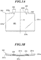
- FIG. 3A is a diagram showing a front view (opposite driver side) of a combiner 200 according to a first embodiment
- FIG. 3B is a diagram showing a top view of the combiner 200
- the combiner 200 is formed as one by molding a transparent resin such as polycarbonate, COP, and acrylic by injection molding (mold internal pressure sensor may be used).
- the combiner 200 includes a projector 201, a supporter 202 formed in one edge of the projector 201, engaging units (member engaging unit) 203 which are a pair of rectangular plates linked to the supporter 202.
- a projecting surface (one optical surface) 201a of a projector 201 is a toric surface (free-form surface or spherical surface) in a suitable concave shape to form a virtual image
- the rear surface (other optical surface) 201c is a spherical surface or aspherical surface in a similar convex shape.
- a plate thickness of the projector 201 is constant, but the thickness may increase or decrease farther from the center.
- the surface of the projector 201 includes a half mirror function with a transmittance of 70% or more and 80% or less.
- a hard coat By forming a hard coat on the entire surface of the combiner 200, it becomes resistant to scratches.
- the refractive index of the hard coat attached to the combiner 200 has substantially the same refractive index as the combiner 200.
- the hard coat is applied using a dipping method, a spray method, a flow method, and a spinning method. The dipping method is used in the later-described example.
- the film thickness of the hard coat is applied in a range of 0.5 ⁇ to 20 ⁇ m, preferably 1 to 10 ⁇ m.
- an upper edge surface 201b which is positioned at the top when attached to the vehicle body VH and a side edge surface 201e are formed.
- the projecting surface 201a is preferably a spherical surface or an aspherical surface with a curvature radius of 100 mm or more, preferably 200 mm or more and 800 mm or less.
- the combiner 200 may be attached to the vehicle body VH by inserting bolts BT (see FIG. 2 ) through the attaching holes 202a and 202b to be screwed on to a part of the vehicle body VH or by using adhesive to be fixed to a portion of the vehicle body VH.
- the method to fix the combiner 200 to the vehicle body VH is not limited to the above.
- the engaging unit 203 formed in the same plate shape is formed separated in an even interval from a center line CL of the combiner 200 and each surface of one engaging unit 203 exists on the same plane as each surface of the other engaging unit 203.
- the plate thickness of the engaging unit 203 can be thinner than the plate thickness of the projector 201, or may be thicker. Alternatively, the thickness can be the same.
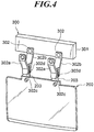
- FIG. 4 is a diagram showing a state in which the jig 300 holds the combiner 200.
- the jig 300 includes a plate shaped frame 301 which can be moved three dimensionally supported by a stage (not shown), and a pair of holders 302, 302 which are attached separated from each other on the same surface as the frame 301.
- the holders 302 are shaped like a clothespin, and each holder 302 includes a pair of arms 302a and 302b, and a coil spring (not shown) positioned between the above.
- the arms 302a and 302b included in the jig engaging unit are linked pivotable in the middle, and the coil spring (not shown) is biased to close the lower edge of the arms 302a and 302b.
- the upper edges of the arms 302b are linked to the frame 301.
- a holding surface 302d provided in the lower edge of the arm 302b is a planar surface, and the holding surfaces of the pair of arms 302b exist on the same plane.
- a lower edge holding surface 302c of the arm 302a opposed to the holding surface 302d may be a planar surface and may be provided with a material to prevent slipping such as rubber.
- the upper edge of the arm 302a is driven, the lower edges of the arms 302a and 302b open, and the holding surfaces 302c and 302d are separated.
- the actuator is turned off, the urging force of the coil spring causes the lower edge of the arms 302a and 302b to close.
- the opening/closing operation is performed synchronized in the pair of holders 302.
- the upper edges of the pair of arms 302a collides with another member at a predetermined opening/closing position and the frame 301 may move so that the lower edge of the arms 302a and 302b can be opened/closed. With this, there is no need for the actuator.
- FIG. 5 is a diagram showing the combiner 200 held by the jig 300 being dipped.
- the combiner 200 before being processed is stored in a state standing in a storage.
- the stage which moves according to a three-dimensional coordinate input in advance
- the frame 301 is positioned above the combiner 200 before processing, the lower edges of the arms 302a and 302b open with the on operation of the actuator, and the frame is lowered from this position.
- the frame 301 is stopped. With the off operation of the actuator, the holding surfaces 302c and 302d are brought close to each other with the urging force of the coil spring, and the holding surfaces 302c and 302d come into contact and press both surfaces of the engaging units 203. With this, the engaging unit 203 is held by the holding unit 302. Here, frictional force occurs between the holding surfaces 302c and 302d and both surfaces of the engaging units 203.
- the combiner 200 is also raised in a state with the engaging units 203 held by the arms 302a and 302b.
- the frame 301 is moved above the liquid tank VL in which hard coat processing liquid HPL is accumulated, the frame 301 is lowered until the hard coat processing liquid surface comes to a defined position with relation to the projecting surface (one optical surface) 201a and the rear surface (other optical surface) 201c of the projector 201.
- the frame 301 is raised, the combiner 200 is raised from the liquid tank VL, and the combiner 200 is conveyed with the frame 300 to perform the following processes.
- the jig 300 releases the combiner 200 and then moves to the storage again.
- the engaging unit 203 is provided for the purpose of conveying, but this may be cut in the later processes if it is not necessary or kept if necessary, depending on the specifications.
- the holding surface 302c aligned accurately in one line supports the surface of the engaging unit 203 aligned accurately in one line similarly, and the jig 300 can securely hold the combiner 200 without damaging the optical surfaces 201a and 201c. With this, it is possible to prevent problems such as the combiner 200 shaking or falling during the movement or processing.
- the holding surfaces 302c aligned accurately in one line support the surface of the engaging unit 203 aligned accurately in one line similarly. Therefore, the jig 300 can hold the combiner 200 accurately. With this, the combiner 200 can be dipped to a suitable position on the liquid surface of the hard coat processing liquid HPL in the liquid tank VL, and with this, the product quality is enhanced.
- the position that the jig 300 holds the combiner 200 is constant. Therefore, the jig 300 is not dipped in the hard coat processing liquid when the combiner 200 is dipped in the hard coat processing liquid. Therefore, it is possible to prevent contamination of the hard coat processing liquid HPL. Further, even if the specifications of the combiner 200 are changed, if the shape of the engaging units 203 is the same, the combiner 200 can be held with the conventional jig 300. Therefore, it is possible to keep the rise in costs due to change in specifications to a minimum.
- "in one line” does not only mean exactly on the same plane, and may include situations in which the units are tilted within plus/minus five degrees from each other.
- FIG. 6 is a diagram showing the combiner 200 held by the jig 300' which is a modification of the present embodiment.
- the holder 302' includes the arms 302a' and 302b', but the length is long so as to cover the pair of engaging units 203 of the combiner 200.
- the other configurations are the same as the above-described embodiment.
- the upper edge of the arm 302a' is driven to open the lower edges of the arms 302a' and 302b' and the holding surfaces 302c' and 302d' are separated.
- the off operation of the actuator the lower edges of the arms 302a' and 302b' are closed by the urging force of the coil spring and the engaging unit 203 is held.
- FIG. 7 is a diagram showing the combiner 200' according to the modification held by the jig 300" according to the modification.
- the combiner 200' includes a cylinder 203a formed on each upper edge of the engaging unit 203'.
- the axes of the two cylinders 203a match with each other.
- the holding surface 302d" provided on the lower edge of the arm 302b" has a cylindrical surface in a concave shape according to an outer circumferential surface of the cylinder 203a, and the holding surfaces 302d" of the pair of arms 302b" have a common axis.
- the holding surface 302c" provided on the lower edge of the arm 302a" is a concave cylindrical surface according to the outer circumferential surface of the cylinder 203a, and the holding surfaces 302c" of the pair of arms 302a" have a common axis.
- the upper edge of the arm 302a" is driven to open the lower edge of the arms 302a” and 302b" and the holding surfaces 302c” and 302d" are separated.
- the lower edge of the arms 302a” and 302b" are closed by the urging force of the coil spring, and the holding surfaces 302c” and 302d" are engaged to the outer circumference of the cylinder 203a without looseness.
- the axis of the cylinder can be parallel or a prism can be provided instead of the cylinder.
- FIG. 8A is a diagram showing a front view (opposite driver side) of the combiner 200A according to a second embodiment.
- FIG. 8B is a diagram showing a top view of the combiner 200A.
- the combiner 200A according to the present embodiment includes a pair of engaging units 203A with a different shape.
- the engaging units 203A include a same plate shape parallel to the optical axis and exist on a position extending parallel to each other. The other configurations are the same as the above-described embodiment.
- FIG. 9 is a diagram showing the jig 300A according to the second embodiment holding the combiner 200A.
- the upper edge of the arm 302b is linked to both opposing edges of an attaching unit 301a projecting in a rectangular plate shape from the bottom edge of the frame 301A.
- the configuration of the holder 302 is the same as the first embodiment.
- the holding surfaces 302d of the pair of arms 302b are in the same interval as the engaging unit 203A of the combiner 200A and parallel to each other.
- the other configurations are the same as the above-described embodiment.
- "parallel" does not only mean exactly parallel, and may include situations in which the units are tilted within plus/minus five degrees from each other.
- the upper edge of the arm 302a is driven to open the lower edges of the arms 302a and 302b and the holding surfaces 302c and 302d are separated.
- the off operation of the actuator the lower edges of the arms 302a and 302b are closed by the urging force of the coil spring and the engaging unit 203A can be held.
- FIG. 10 is a diagram showing the jig 300B according to the third embodiment holding the combiner 200.
- the jig 300B according to the present embodiment supports the holder 302 through an automatic angle adjusting mechanism 310.
- the configuration of the holder 302 is similar to the first embodiment. Similar to the first embodiment, in the combiner 200, the engaging units 203 are formed separated in an even interval from the center line CL of the combiner 200, and the surfaces of one engaging unit 203 exist on the same plane as the surfaces of the other engaging unit 203. Specifically, a horizontal axis 311 is positioned to be able to slide in openings 302e and 302f formed on the upper edge of the arms 302a and 302b.
- the linking unit 312 in a cube shape is formed in the center of the horizontal axis 311, a vertical axis 313 extends upward from the linking unit 312, and the upper edge of the vertical axis 313 is supported to be able to rotate by a bearing 314 connected to the lower edge of the frame 301.
- the lower edges of the arms 302a and 302b are opened, and the holding surfaces 302c and 302d are separated.
- the off operation of the actuator the lower edges of the arms 302a and 302b are closed by the urging force of the coil spring and the engaging unit 203 is held.
- the automatic angle adjustment mechanism 310 since the automatic angle adjustment mechanism 310 is provided, when there is a tilt in the holding surfaces 302ca and 302d, the vertical axis 313 rotates in accordance with the holding surfaces 302c and 302d coming into contact with both surfaces of the engaging unit 203, and with this, the arms 302a and 302b are tilted similar to the engaging unit 203. Therefore, the engaging unit 203 can be held suitably.
- the engaging unit 203A from the upper edge of the combiner 200A includes a same plate shape parallel to the optical axis and exist on a position extending parallel to each other, since the automatic angle adjustment mechanism 310 is provided, the vertical axis 313 rotates. With this, the arms 302a and 302b are tilted similar to the engaging unit 203. With this, the engaging unit 203 can be suitably held.
- the present invention is not limited to the embodiments described in this description. It is clear to those skilled in the art from the embodiments and ideas described in the description that other embodiments and modifications are included in the present invention.
- the display member and the head-up display device according to the present invention is not limited to use in automobiles and can also be used in airplanes and heavy machinery.
- the processing liquid is not limited to hard coat processing liquid and includes processing liquid to form various layers such as antifouling coat, antireflective coat, and the like.
- the present invention can be used in a display member, a head-up display device and a jig.
Landscapes
- Engineering & Computer Science (AREA)
- Chemical & Material Sciences (AREA)
- Combustion & Propulsion (AREA)
- Transportation (AREA)
- Mechanical Engineering (AREA)
- Physics & Mathematics (AREA)
- General Physics & Mathematics (AREA)
- Optics & Photonics (AREA)
- Instrument Panels (AREA)
- Coating Apparatus (AREA)
- Devices For Indicating Variable Information By Combining Individual Elements (AREA)
Abstract
A display member (200) includes the following. An optical surface (201) on which a predetermined process is performed includes a predetermined curvature. A plurality of member engaging units (203) are linked to the optical surface (201). The member engaging units (203) are formed aligned in one line or aligned parallel, and are held by a jig engaging unit (302) of a jig (300). The member engaging units (203) are held by the jig engaging unit (302) and the display member (200) is held through the jig (300) during the predetermined process.
Description
- The present invention relates to a head-up display device mainly used in an automobile, for example. More specifically, the present invention relates to a display member which is preferably used in a head-up display device, a head-up display device, and a jig with which, through a translucent display member (combiner), scenery in front of the vehicle which is viewed by light passing through a combiner and images and information provided by light reflected from the combiner can be viewed overlapped in a visual field of a driver (observer).
- If information such as speed shown on meters in a vehicle can be directly projected on a windshield as a virtual image while a driver is driving an automobile, the driver can drive without changing his visual field, and this may prevent an accident. As a means to directly project information to a visual field of a human, a head-up display device is developed. Usually in such head-up display device, light emitted from a projector such as a small liquid crystal projector passes light and reflects light with a combiner (display member) formed from a transparent base including a half mirror or a windshield. Therefore, a driver (observer) is able to obtain information displayed on the combiner and is also able to obtain at the same time outside information such as outside scenery through the combiner.
- A hard coat layer may be provided in a layer forming a surface of a combiner in order to provide a certain degree of hardness to the combiner for the purpose of preventing cracks. The hard coat layer can be typically formed by dipping the material of the combiner in a processing liquid and then drying and hardening the above. In such case, there is a problem of how to dip the material of the combiner formed by injection molding in the processing liquid.
- Patent Literature 1 discloses a technique to hold an edge surface of the material to be coated between a jig above the liquid and a jig in the liquid having a scissor shape when the material to be coated in a plate shape is dipped in coating liquid in a liquid tank by a dip coating method. According to Patent Literature 1, when the material to be coated is a thin plate shape as in a combiner, if the edge surface is held with a scissor shaped jig, the material may easily fall out of the jig if force is applied in the direction that the material to be coated falls. If the power to hold is increased in the jig to prevent such case, a mark where the edge surface is pressed may remain on the edge surface of the material to be coated, and this may reduce the quality of the product. Moreover, if the jig in the liquid is driven in the coating liquid, dust from sliding may be generated and the coating liquid may be contaminated.
-
- Patent Literature 1: Japanese Patent Application Laid-Open Publication No.
H08-299891 - Patent Literature 2: Japanese Patent Application Laid-Open Publication No.
H09-248507 - In view of the above, Patent Literature 2 discloses a configuration in which one end of a S-shaped hook is hooked to a moving round stick, the other end is hooked to a hole of the base, and the base in a hung state is dipped in the dipping section. According to the technique disclosed in Patent Literature 2, the base can be dipped in the dipping unit without a mark remaining. However, when the base shakes or falls in the liquid, the base cannot be dipped accurately to a defined position. Moreover, if a hole is provided only for the purpose of hanging the base, this hole remains in the completed product. Therefore, this also reduces the quality of the product.
- The present invention is made in view of the above problems, and the purpose of the present invention is to provide a display member which is suitably held in order to be able to perform a predetermined process, a head-up display device which uses such display member, and a jig which holds such display member.
- According to the present invention, a display member includes: an optical surface on which a predetermined process is performed and which includes a predetermined curvature; and a plurality of member engaging units linked to the optical surface, wherein, the member engaging units are formed aligned in one line or aligned parallel, and are held by a jig engaging unit of a jig, and the member engaging units are held by the jig engaging unit and the display member is held through the jig during the predetermined process.
- According to the present invention, a display member which is suitably held in order to be able to perform a predetermined process, a head-up display device which uses such display member, and a jig which holds such display member can be provided.
-
-
FIG. 1 is a diagram showing a state in which a head-up display device is mounted on a vehicle body VH. -
FIG. 2 is a diagram showing a configuration of adrawing unit 100. -
FIG. 3A is a diagram showing a front view (opposite driver side) of acombiner 200 according to a first embodiment. -
FIG. 3B is a diagram showing a top view of thecombiner 200 according to the first embodiment. -
FIG. 4 is a diagram showing a state holding thecombiner 200 with thejig 300. -
FIG. 5 is a diagram showing thecombiner 200 held by thejig 300 being dipped. -
FIG. 6 is a diagram showing a state holding thecombiner 200 with a jig 300' which is a modification of an embodiment. -
FIG. 7 is a diagram showing a state holding the combiner 200' of the modification with ajig 300" according to the modification. -
FIG. 8A is a diagram showing a front view (opposite driver side) of acombiner 200A according to a second embodiment. -
FIG. 8B is a diagram showing an upper view of thecombiner 200A according to the second embodiment. -
FIG. 9 is a diagram showing a state holding acombiner 200A with ajig 300A according to the second embodiment. -
FIG. 10 is a diagram showing a state holding acombiner 200 with ajig 300B according to the third embodiment. - An embodiment of the present invention is described with reference to the drawings.
FIG. 1 is a diagram showing a state of a head-up display device according to the present embodiment mounted on a vehicle body VH. Adrawing unit 100 is positioned in a dashboard DB of the vehicle body VH and thedrawing unit 100 projects display light to a combiner 200 as a display member positioned fixed on the dashboard DB. Such display light is guided to a pupil of a driver DR who is the observer by reflection or diffraction, and a virtual image (display image) is displayed. The driver DR is able to observe a real image such as scenery passing through a windshield WS and thecombiner 200 overlapped with the virtual image. Thecombiner 200 may be foldable or may slide vertically to be storable in the dashboard DB. The head-up display device includes thedrawing unit 100 and thecombiner 200. -
FIG. 2 is a diagram showing a schematic configuration of adrawing unit 100. Thedrawing unit 100 mainly includes adrawing device 110 including a liquidcrystal display panel 111, aconcave mirror 120, and ahousing 130. The configuration of the drawing device is described in detail in, for example, Japanese Patent Application Laid-Open Publication No.2012-203176 - The liquid
crystal display panel 111 is formed by attaching polarizing plates on both the front surface and the rear surface of a liquid crystal cell enclosing a liquid crystal layer in a pair of translucent substrates in which a transparent electrode film is formed. The light guided from a light source (not shown) in thedrawing device 110 to a surface of the liquidcrystal display panel 111 passes through the liquidcrystal display panel 111 and becomes the display light L. The light is illuminated on the concave mirror (or planar mirror) 120 included in a projection optical system. After the light is reflected, the light heads toward thecombiner 200. Thecombiner 200 is a plate formed in a plate shape with a thickness of 3 to 5 mm (preferably, no larger than 10 mm). A projecting surface of the combiner 200 (driver side) is a toric surface (can also be a free-form surface or spherical surface) in a concave shape with a curvature radius of 100 mm or more to form a virtual image and the rear surface (vehicle front side) is a spherical surface or an aspherical surface similar to the above. -
FIG. 3A is a diagram showing a front view (opposite driver side) of acombiner 200 according to a first embodiment, andFIG. 3B is a diagram showing a top view of thecombiner 200. For example, thecombiner 200 is formed as one by molding a transparent resin such as polycarbonate, COP, and acrylic by injection molding (mold internal pressure sensor may be used). Thecombiner 200 includes aprojector 201, asupporter 202 formed in one edge of theprojector 201, engaging units (member engaging unit) 203 which are a pair of rectangular plates linked to thesupporter 202. A projecting surface (one optical surface) 201a of aprojector 201 is a toric surface (free-form surface or spherical surface) in a suitable concave shape to form a virtual image, and the rear surface (other optical surface) 201c is a spherical surface or aspherical surface in a similar convex shape. Preferably, a plate thickness of theprojector 201 is constant, but the thickness may increase or decrease farther from the center. - By vapor depositing a well-known half mirror film, preferably, the surface of the
projector 201 includes a half mirror function with a transmittance of 70% or more and 80% or less. By forming a hard coat on the entire surface of thecombiner 200, it becomes resistant to scratches. Preferably, the refractive index of the hard coat attached to thecombiner 200 has substantially the same refractive index as thecombiner 200. The hard coat is applied using a dipping method, a spray method, a flow method, and a spinning method. The dipping method is used in the later-described example. The film thickness of the hard coat is applied in a range of 0.5µ to 20µm, preferably 1 to 10µm. - As an edge surface (edge) of the
projector 201, anupper edge surface 201b which is positioned at the top when attached to the vehicle body VH and aside edge surface 201e are formed. The projectingsurface 201a is preferably a spherical surface or an aspherical surface with a curvature radius of 100 mm or more, preferably 200 mm or more and 800 mm or less. - Two attaching
holes single supporter 202. Thecombiner 200 may be attached to the vehicle body VH by inserting bolts BT (seeFIG. 2 ) through the attachingholes combiner 200 to the vehicle body VH is not limited to the above. - The engaging
unit 203 formed in the same plate shape is formed separated in an even interval from a center line CL of thecombiner 200 and each surface of one engagingunit 203 exists on the same plane as each surface of the other engagingunit 203. The plate thickness of the engagingunit 203 can be thinner than the plate thickness of theprojector 201, or may be thicker. Alternatively, the thickness can be the same. -
FIG. 4 is a diagram showing a state in which thejig 300 holds thecombiner 200. As shown inFIG. 4 , thejig 300 includes a plate shapedframe 301 which can be moved three dimensionally supported by a stage (not shown), and a pair ofholders frame 301. - The
holders 302 are shaped like a clothespin, and eachholder 302 includes a pair ofarms arms arms arms 302b are linked to theframe 301. A holdingsurface 302d provided in the lower edge of thearm 302b is a planar surface, and the holding surfaces of the pair ofarms 302b exist on the same plane. A loweredge holding surface 302c of thearm 302a opposed to the holdingsurface 302d may be a planar surface and may be provided with a material to prevent slipping such as rubber. - By turning on an actuator (not shown), the upper edge of the
arm 302a is driven, the lower edges of thearms arms holders 302. The upper edges of the pair ofarms 302a collides with another member at a predetermined opening/closing position and theframe 301 may move so that the lower edge of thearms - Next, the surface processing method of the
combiner 200 which is the predetermined process is described with reference to the drawings.FIG. 5 is a diagram showing thecombiner 200 held by thejig 300 being dipped. Although not shown, thecombiner 200 before being processed is stored in a state standing in a storage. For example, using the stage (not shown) which moves according to a three-dimensional coordinate input in advance, theframe 301 is positioned above thecombiner 200 before processing, the lower edges of thearms - When the holding surfaces 302c and 302d reach a position facing the engaging
units 203 of thecombiner 200, theframe 301 is stopped. With the off operation of the actuator, the holdingsurfaces units 203. With this, the engagingunit 203 is held by the holdingunit 302. Here, frictional force occurs between the holdingsurfaces units 203. When theframe 301 is raised as is, thecombiner 200 is also raised in a state with the engagingunits 203 held by thearms - Then, as shown in
FIG. 5 , after theframe 301 is moved above the liquid tank VL in which hard coat processing liquid HPL is accumulated, theframe 301 is lowered until the hard coat processing liquid surface comes to a defined position with relation to the projecting surface (one optical surface) 201a and the rear surface (other optical surface) 201c of theprojector 201. After theprojector 201 and thesupporter 202 are dipped in the hard coat processing liquid HPL, theframe 301 is raised, thecombiner 200 is raised from the liquid tank VL, and thecombiner 200 is conveyed with theframe 300 to perform the following processes. Here, thejig 300 releases thecombiner 200 and then moves to the storage again. The engagingunit 203 is provided for the purpose of conveying, but this may be cut in the later processes if it is not necessary or kept if necessary, depending on the specifications. - According to the present embodiment, the holding
surface 302c aligned accurately in one line supports the surface of the engagingunit 203 aligned accurately in one line similarly, and thejig 300 can securely hold thecombiner 200 without damaging theoptical surfaces combiner 200 shaking or falling during the movement or processing. The holding surfaces 302c aligned accurately in one line support the surface of the engagingunit 203 aligned accurately in one line similarly. Therefore, thejig 300 can hold thecombiner 200 accurately. With this, thecombiner 200 can be dipped to a suitable position on the liquid surface of the hard coat processing liquid HPL in the liquid tank VL, and with this, the product quality is enhanced. The position that thejig 300 holds thecombiner 200 is constant. Therefore, thejig 300 is not dipped in the hard coat processing liquid when thecombiner 200 is dipped in the hard coat processing liquid. Therefore, it is possible to prevent contamination of the hard coat processing liquid HPL. Further, even if the specifications of thecombiner 200 are changed, if the shape of the engagingunits 203 is the same, thecombiner 200 can be held with theconventional jig 300. Therefore, it is possible to keep the rise in costs due to change in specifications to a minimum. Here, "in one line" does not only mean exactly on the same plane, and may include situations in which the units are tilted within plus/minus five degrees from each other. -
FIG. 6 is a diagram showing thecombiner 200 held by the jig 300' which is a modification of the present embodiment. According to this example, inFIG. 6 , only one holder 302' is attached to theframe 301. The holder 302' includes thearms 302a' and 302b', but the length is long so as to cover the pair of engagingunits 203 of thecombiner 200. The other configurations are the same as the above-described embodiment. - According to the modification shown in
FIG. 6 also, with the on operation of the actuator (not shown), the upper edge of thearm 302a' is driven to open the lower edges of thearms 302a' and 302b' and the holding surfaces 302c' and 302d' are separated. With the off operation of the actuator, the lower edges of thearms 302a' and 302b' are closed by the urging force of the coil spring and the engagingunit 203 is held. -
FIG. 7 is a diagram showing the combiner 200' according to the modification held by thejig 300" according to the modification. The combiner 200' includes acylinder 203a formed on each upper edge of the engaging unit 203'. The axes of the twocylinders 203a match with each other. The holdingsurface 302d" provided on the lower edge of thearm 302b" has a cylindrical surface in a concave shape according to an outer circumferential surface of thecylinder 203a, and the holding surfaces 302d" of the pair ofarms 302b" have a common axis. The holdingsurface 302c" provided on the lower edge of thearm 302a" is a concave cylindrical surface according to the outer circumferential surface of thecylinder 203a, and the holdingsurfaces 302c" of the pair ofarms 302a" have a common axis. - According to the modification shown in
FIG. 7 , with the on operation of the actuator (not shown), the upper edge of thearm 302a" is driven to open the lower edge of thearms 302a" and 302b" and the holdingsurfaces 302c" and 302d" are separated. With the off operation of the actuator, the lower edge of thearms 302a" and 302b" are closed by the urging force of the coil spring, and the holdingsurfaces 302c" and 302d" are engaged to the outer circumference of thecylinder 203a without looseness. The axis of the cylinder can be parallel or a prism can be provided instead of the cylinder. -
FIG. 8A is a diagram showing a front view (opposite driver side) of thecombiner 200A according to a second embodiment.FIG. 8B is a diagram showing a top view of thecombiner 200A. Thecombiner 200A according to the present embodiment includes a pair of engagingunits 203A with a different shape. The engagingunits 203A include a same plate shape parallel to the optical axis and exist on a position extending parallel to each other. The other configurations are the same as the above-described embodiment. -
FIG. 9 is a diagram showing thejig 300A according to the second embodiment holding thecombiner 200A. As shown inFIG. 9 , in thejig 300A, the upper edge of thearm 302b is linked to both opposing edges of an attachingunit 301a projecting in a rectangular plate shape from the bottom edge of theframe 301A. The configuration of theholder 302 is the same as the first embodiment. Here, the holding surfaces 302d of the pair ofarms 302b are in the same interval as the engagingunit 203A of thecombiner 200A and parallel to each other. The other configurations are the same as the above-described embodiment. Here, "parallel" does not only mean exactly parallel, and may include situations in which the units are tilted within plus/minus five degrees from each other. - According to the present embodiment, with the on operation of the actuator (not shown), the upper edge of the
arm 302a is driven to open the lower edges of thearms arms unit 203A can be held. -
FIG. 10 is a diagram showing thejig 300B according to the third embodiment holding thecombiner 200. Thejig 300B according to the present embodiment supports theholder 302 through an automaticangle adjusting mechanism 310. The configuration of theholder 302 is similar to the first embodiment. Similar to the first embodiment, in thecombiner 200, the engagingunits 203 are formed separated in an even interval from the center line CL of thecombiner 200, and the surfaces of one engagingunit 203 exist on the same plane as the surfaces of the other engagingunit 203. Specifically, ahorizontal axis 311 is positioned to be able to slide inopenings arms unit 312 in a cube shape is formed in the center of thehorizontal axis 311, avertical axis 313 extends upward from the linkingunit 312, and the upper edge of thevertical axis 313 is supported to be able to rotate by a bearing 314 connected to the lower edge of theframe 301. - According to the present embodiment, with the on operation of the actuator (not shown), the lower edges of the
arms arms unit 203 is held. - Here, when there is a tilt due to defects in molding between the pair of engaging
units 203 which are to exist on the same plane, if the holding surfaces 302c and 302d are exactly aligned in the pair ofholders 302, stress may occur on the engagingunit 203 when the holding surfaces 302c and 302d contact both surfaces of the engagingunit 203 to a degree that fracture may occur from the base. - According to the present embodiment, since the automatic
angle adjustment mechanism 310 is provided, when there is a tilt in the holding surfaces 302ca and 302d, thevertical axis 313 rotates in accordance with the holding surfaces 302c and 302d coming into contact with both surfaces of the engagingunit 203, and with this, thearms unit 203. Therefore, the engagingunit 203 can be held suitably. - As in the second embodiment shown in
FIG. 8 , when the engagingunit 203A from the upper edge of thecombiner 200A includes a same plate shape parallel to the optical axis and exist on a position extending parallel to each other, since the automaticangle adjustment mechanism 310 is provided, thevertical axis 313 rotates. With this, thearms unit 203. With this, the engagingunit 203 can be suitably held. - The present invention is not limited to the embodiments described in this description. It is clear to those skilled in the art from the embodiments and ideas described in the description that other embodiments and modifications are included in the present invention. For example, the display member and the head-up display device according to the present invention is not limited to use in automobiles and can also be used in airplanes and heavy machinery. The processing liquid is not limited to hard coat processing liquid and includes processing liquid to form various layers such as antifouling coat, antireflective coat, and the like.
- The present invention can be used in a display member, a head-up display device and a jig.
-
- 100 drawing unit
- 110 drawing device
- 111 liquid crystal display panel
- 120 concave mirror
- 130 housing
- 200, 200', 200A combiner
- 201 projector
- 201a, 201c projecting surface
- 201b upper edge surface
- 201e side edge surface
- 202 supporter
- 202a attaching hole
- 203, 203', 203A engaging unit
- 203a cylinder
- 300, 300", 300A, 300B jig
- 301, 301A frame
- 301a attaching unit
- 302 holder
- 302a, 302a', 302a" arm
- 302b, 302b', 302b" arm
- 302c, 302c', 302c" holding surface
- 302d, 302d', 302d" holding surface
- 302e, 302f opening
- 310 automatic angle adjusting mechanism
- 311 horizontal axis
- 312 linking unit
- 313 vertical axis
- 314 bearing
- BT bolt
- DB dashboard
- DR driver
- HPL hard coat processing liquid
- L display light
- VH vehicle
- VL liquid tank
- WS windshield
Claims (7)
- A display member comprising:an optical surface on which a predetermined process is performed and which includes a predetermined curvature; anda plurality of member engaging units linked to the optical surface,wherein, the member engaging units are formed aligned in one line or aligned parallel, and are held by a jig engaging unit of a jig, andthe member engaging units are held by the jig engaging unit and the display member is held through the jig during the predetermined process.
- The display member according to claim 1, wherein the predetermined process is a process in which the optical surface of the display member held by the jig is dipped in a processing liquid.
- The display member according to claim 1 or 2, wherein the member engaging units are cut after the predetermined process.
- A head-up display device comprising:a display member according to any one of claims 1 to 3; anda drawing unit which emits a display light to the display member.
- A jig which holds the display member according to any one of claims 1 to 3, the jig comprising:
a jig engaging unit which holds both surfaces of the plurality of member engaging units. - The jig according to claim 5, wherein, the predetermined process is a process in which the optical surface of the display member held by the jig is dipped in the processing liquid, and the jig engaging unit is not dipped in the processing liquid.
- The jig according to claim 5 or 6, wherein the jig engaging unit includes a plate, a prism or a cylinder aligned in one line or aligned in parallel.
Applications Claiming Priority (2)
| Application Number | Priority Date | Filing Date | Title |
|---|---|---|---|
| JP2016222990 | 2016-11-16 | ||
| PCT/JP2017/040081 WO2018092636A1 (en) | 2016-11-16 | 2017-11-07 | Display member, head-up display device, and jig |
Publications (1)
| Publication Number | Publication Date |
|---|---|
| EP3543765A1 true EP3543765A1 (en) | 2019-09-25 |
Family
ID=62145343
Family Applications (1)
| Application Number | Title | Priority Date | Filing Date |
|---|---|---|---|
| EP17871662.7A Withdrawn EP3543765A1 (en) | 2016-11-16 | 2017-11-07 | Display member, head-up display device, and jig |
Country Status (5)
| Country | Link |
|---|---|
| US (1) | US20190275556A1 (en) |
| EP (1) | EP3543765A1 (en) |
| JP (1) | JPWO2018092636A1 (en) |
| CN (1) | CN109983391A (en) |
| WO (1) | WO2018092636A1 (en) |
Families Citing this family (1)
| Publication number | Priority date | Publication date | Assignee | Title |
|---|---|---|---|---|
| DE102019122574A1 (en) * | 2019-08-22 | 2021-02-25 | Valeo Schalter Und Sensoren Gmbh | Adjustment device, adjustment unit, head-up display and motor vehicle |
Family Cites Families (13)
| Publication number | Priority date | Publication date | Assignee | Title |
|---|---|---|---|---|
| JP2546243Y2 (en) * | 1992-02-14 | 1997-08-27 | 矢崎総業株式会社 | Front glass shape for vehicle display device |
| JPH08299891A (en) | 1995-05-10 | 1996-11-19 | Canon Inc | Dip coating method |
| US5718849A (en) * | 1995-09-25 | 1998-02-17 | Galic Maus Ventures | Method and apparatus for injection-compression molding & ejecting paired thermoplastic spectacle lens suited for fully automated dip hardcoating |
| JPH09248507A (en) | 1996-03-15 | 1997-09-22 | Toray Ind Inc | Dip coating equipment |
| JP3320302B2 (en) * | 1996-04-10 | 2002-09-03 | ホーヤ株式会社 | Injection compression molding method for lenses |
| JP3826460B2 (en) * | 1996-12-13 | 2006-09-27 | 株式会社島津製作所 | Combiner and its manufacturing method |
| JP2000128580A (en) * | 1998-10-21 | 2000-05-09 | Toyota Motor Corp | Dip coating method for glass substrate |
| JP2007321242A (en) * | 2006-06-05 | 2007-12-13 | Marunaka Kogyo Kk | Clip type workpiece hanger in electroplating device |
| JP5674032B2 (en) | 2011-03-25 | 2015-02-18 | 日本精機株式会社 | Head-up display device |
| JP5887933B2 (en) * | 2011-12-28 | 2016-03-16 | 日本精機株式会社 | Head-up display device |
| JP6123229B2 (en) * | 2012-10-30 | 2017-05-10 | コニカミノルタ株式会社 | Combiner manufacturing method and combiner |
| JP2014088600A (en) * | 2012-10-31 | 2014-05-15 | C Uyemura & Co Ltd | Surface treating device |
| WO2017204133A1 (en) * | 2016-05-25 | 2017-11-30 | コニカミノルタ株式会社 | Display member production method, display member, and head-up display device |
-
2017
- 2017-11-07 US US16/346,574 patent/US20190275556A1/en not_active Abandoned
- 2017-11-07 JP JP2018551578A patent/JPWO2018092636A1/en active Pending
- 2017-11-07 CN CN201780070102.2A patent/CN109983391A/en active Pending
- 2017-11-07 WO PCT/JP2017/040081 patent/WO2018092636A1/en not_active Ceased
- 2017-11-07 EP EP17871662.7A patent/EP3543765A1/en not_active Withdrawn
Also Published As
| Publication number | Publication date |
|---|---|
| US20190275556A1 (en) | 2019-09-12 |
| WO2018092636A1 (en) | 2018-05-24 |
| CN109983391A (en) | 2019-07-05 |
| JPWO2018092636A1 (en) | 2019-10-17 |
Similar Documents
| Publication | Publication Date | Title |
|---|---|---|
| CN106740116B (en) | Integral head-up display device | |
| US20180203236A1 (en) | Optical system and head-mounted display device | |
| US20090141363A1 (en) | Head up display device | |
| CN108698513B (en) | Projection type display device, projection control method, and recording medium | |
| WO1989003059A3 (en) | Automobile head-up display system | |
| JP2011247997A (en) | Head-up display device | |
| US20170307885A1 (en) | Head-up display for a motor vehicle | |
| AU2013227443B2 (en) | Lens deployment apparatus | |
| US20170052372A1 (en) | Vehicular display device | |
| JP2000249965A (en) | Information display device | |
| WO2017067528A1 (en) | Separated head up display | |
| EP3543765A1 (en) | Display member, head-up display device, and jig | |
| EP3543764A1 (en) | Display member, head-up display device, and jig | |
| JP2017049570A (en) | Mirror unit | |
| JP2017102230A (en) | Mirror unit | |
| CN109789780A (en) | Projection display device | |
| EP4099085A1 (en) | Image display device | |
| JP6615389B2 (en) | Head-up display device | |
| US12449658B2 (en) | Image display device | |
| CN110161695A (en) | A kind of automobile head-up display optical texture that image-forming range is variable | |
| JP2017194615A (en) | Mirror unit | |
| CN106796353A (en) | Housing for a head-up display of a motor vehicle and method for providing the same | |
| JPH0930289A (en) | Head-up display device | |
| WO2017204133A1 (en) | Display member production method, display member, and head-up display device | |
| EP3628076B1 (en) | Dual mode headset |
Legal Events
| Date | Code | Title | Description |
|---|---|---|---|
| PUAI | Public reference made under article 153(3) epc to a published international application that has entered the european phase |
Free format text: ORIGINAL CODE: 0009012 |
|
| STAA | Information on the status of an ep patent application or granted ep patent |
Free format text: STATUS: THE APPLICATION HAS BEEN WITHDRAWN |
|
| 17P | Request for examination filed |
Effective date: 20190514 |
|
| AK | Designated contracting states |
Kind code of ref document: A1 Designated state(s): AL AT BE BG CH CY CZ DE DK EE ES FI FR GB GR HR HU IE IS IT LI LT LU LV MC MK MT NL NO PL PT RO RS SE SI SK SM TR |
|
| AX | Request for extension of the european patent |
Extension state: BA ME |
|
| 18W | Application withdrawn |
Effective date: 20190909 |