EP3543596A1 - Lichtmodul für einen kraftfahrzeugscheinwerfer - Google Patents
Lichtmodul für einen kraftfahrzeugscheinwerfer Download PDFInfo
- Publication number
- EP3543596A1 EP3543596A1 EP18162863.7A EP18162863A EP3543596A1 EP 3543596 A1 EP3543596 A1 EP 3543596A1 EP 18162863 A EP18162863 A EP 18162863A EP 3543596 A1 EP3543596 A1 EP 3543596A1
- Authority
- EP
- European Patent Office
- Prior art keywords
- light module
- conversion
- light
- phosphor
- module according
- Prior art date
- Legal status (The legal status is an assumption and is not a legal conclusion. Google has not performed a legal analysis and makes no representation as to the accuracy of the status listed.)
- Granted
Links
Images

Classifications
-
- F—MECHANICAL ENGINEERING; LIGHTING; HEATING; WEAPONS; BLASTING
- F21—LIGHTING
- F21S—NON-PORTABLE LIGHTING DEVICES; SYSTEMS THEREOF; VEHICLE LIGHTING DEVICES SPECIALLY ADAPTED FOR VEHICLE EXTERIORS
- F21S41/00—Illuminating devices specially adapted for vehicle exteriors, e.g. headlamps
- F21S41/30—Illuminating devices specially adapted for vehicle exteriors, e.g. headlamps characterised by reflectors
-
- F—MECHANICAL ENGINEERING; LIGHTING; HEATING; WEAPONS; BLASTING
- F21—LIGHTING
- F21S—NON-PORTABLE LIGHTING DEVICES; SYSTEMS THEREOF; VEHICLE LIGHTING DEVICES SPECIALLY ADAPTED FOR VEHICLE EXTERIORS
- F21S41/00—Illuminating devices specially adapted for vehicle exteriors, e.g. headlamps
- F21S41/10—Illuminating devices specially adapted for vehicle exteriors, e.g. headlamps characterised by the light source
- F21S41/14—Illuminating devices specially adapted for vehicle exteriors, e.g. headlamps characterised by the light source characterised by the type of light source
- F21S41/16—Laser light sources
-
- F—MECHANICAL ENGINEERING; LIGHTING; HEATING; WEAPONS; BLASTING
- F21—LIGHTING
- F21S—NON-PORTABLE LIGHTING DEVICES; SYSTEMS THEREOF; VEHICLE LIGHTING DEVICES SPECIALLY ADAPTED FOR VEHICLE EXTERIORS
- F21S41/00—Illuminating devices specially adapted for vehicle exteriors, e.g. headlamps
- F21S41/10—Illuminating devices specially adapted for vehicle exteriors, e.g. headlamps characterised by the light source
- F21S41/14—Illuminating devices specially adapted for vehicle exteriors, e.g. headlamps characterised by the light source characterised by the type of light source
- F21S41/176—Light sources where the light is generated by photoluminescent material spaced from a primary light generating element
-
- F—MECHANICAL ENGINEERING; LIGHTING; HEATING; WEAPONS; BLASTING
- F21—LIGHTING
- F21V—FUNCTIONAL FEATURES OR DETAILS OF LIGHTING DEVICES OR SYSTEMS THEREOF; STRUCTURAL COMBINATIONS OF LIGHTING DEVICES WITH OTHER ARTICLES, NOT OTHERWISE PROVIDED FOR
- F21V7/00—Reflectors for light sources
- F21V7/22—Reflectors for light sources characterised by materials, surface treatments or coatings, e.g. dichroic reflectors
- F21V7/24—Reflectors for light sources characterised by materials, surface treatments or coatings, e.g. dichroic reflectors characterised by the material
-
- F—MECHANICAL ENGINEERING; LIGHTING; HEATING; WEAPONS; BLASTING
- F21—LIGHTING
- F21W—INDEXING SCHEME ASSOCIATED WITH SUBCLASSES F21K, F21L, F21S and F21V, RELATING TO USES OR APPLICATIONS OF LIGHTING DEVICES OR SYSTEMS
- F21W2102/00—Exterior vehicle lighting devices for illuminating purposes
-
- F—MECHANICAL ENGINEERING; LIGHTING; HEATING; WEAPONS; BLASTING
- F21—LIGHTING
- F21Y—INDEXING SCHEME ASSOCIATED WITH SUBCLASSES F21K, F21L, F21S and F21V, RELATING TO THE FORM OR THE KIND OF THE LIGHT SOURCES OR OF THE COLOUR OF THE LIGHT EMITTED
- F21Y2115/00—Light-generating elements of semiconductor light sources
- F21Y2115/30—Semiconductor lasers
Definitions
- the invention relates to a light module for a motor vehicle headlight, which light module comprises a conversion means and a light source, which conversion means comprises a phosphor arranged on a carrier layer, wherein the phosphor has a plurality of conversion segments, which are formed by depressions in the phosphor, wherein the lighting means set is to excite the conversion segments to a light emission with a wavelength conversion.
- the invention also relates to a motor vehicle headlight with at least one light module according to the invention.
- This conversion means is formed, for example, in the form of one or more photoluminescence converters or a phosphor, wherein incident laser beams of the laser device impinge on the usually phosphor having conversion means and excite this phosphor or photoluminescent dye for photoluminescence, while light in the light of the radiating Laser device different wavelength or wavelength ranges is delivered.
- the light output of the conversion means essentially has characteristics of a Lambertian radiator.
- transmissive and transmissive refer to the blue portion of the converted white light.
- transmissive structure is the Main propagation direction of the blue light component after passing through the converter volume or conversion means substantially rectified to the propagation direction of the output laser beam.
- the laser beam is reflected or deflected at an interface attributable to the conversion means, so that the blue light component has a different propagation direction than the laser beam, which is generally designed as a blue laser beam.
- Conversion materials or phosphors for example, from the class of doped compounds with a garnet structure, such as Ce-doped yttrium-aluminum garnet (Ce: YAG), are known from the prior art, with a multiplicity of particles of different size in a binding matrix are assembled, which is fixed on a carrier with high thermal conductivity, for example, sapphire.
- a carrier with high thermal conductivity for example, sapphire.
- structure denotes the nature of the entirety of those sub-volumes, each of which is homogeneous in a first approximation in terms of its composition and the spatial arrangement of its components with respect to a fixed axis coordinate placed in the material.
- the structure is characterized by the type, shape, size, distribution and orientation of the structural components.
- multiphase ceramics for example Ce: YAG together with corundum, can also act as scattering centers.
- a promising measure for the reduction of the lateral luminous spot expansion, in particular in reflective systems, consists in a targeted subdivision of the phosphor into individual segments, starting from an originally compact base ceramic.
- Such segments - referred to below as conversion segments - are produced by recesses introduced into the phosphor.
- a disadvantage of this structuring is that the mechanical strength and overall integrity, for example by microcracks or breakouts in the individual segments, is weakened.
- the contrast properties can be adjusted locally.
- the filler in the recesses prevents possible crosstalk of light rays to an adjacent conversion segment, which also increases the contrast.
- a ceramic material may be provided.
- Insulation / ceramic layers can be applied as filler material using alkoxide sol / gel processes to obtain alumina / silica / mullite / zirconia / rutile deposits, which may also be mixed with one another and more or less pronouncedly crystalline or stoichiometrically exact , where partially prefabricated sols / gels (boehmite AlO (OH), Sasol Disperal®, Akzo Nobel Levasil®, ...) can be used.
- sols / gels partially prefabricated sols / gels (boehmite AlO (OH), Sasol Disperal®, Akzo Nobel Levasil®, ...) can be used.
- the surface tension and / or the drying or heating characteristic, in particular the porosity can be controlled in order to adapt material-specific properties with regard to thermal conductivity, mechanical strength or thermal expansion coefficients.
- the phosphor used may, for example, be polycrystalline sintered or grown or drawn from a melt. Furthermore, a teilamorphes microstructure or single-crystal slices with subsequent introduced structures or impurities as scattering centers is possible.
- the coherent structure of the recesses is achieved by a mechanical method, for example by sawing, laser ablation or Focused Ion Beam.
- the conversion segments thus obtained-also called pixels-can have a width of approximately 50 ⁇ m and a distance of approximately 10 ⁇ m from each other.
- the depressions may in this case have a depth of up to about 100 ⁇ m.
- the recesses have at least in regions at least one electrically conductive and / or optically reflective layer, i. at least one electrically conductive and / or optically reflecting layer is arranged between the filler and the depressions at least in regions.
- the at least one electrically conductive and / or optically reflecting layer is arranged, for example, on the surface of the depressions.
- surface is meant here the walls or the bottom of the recesses and not the surface which forms the surface of the conversion segments.
- This layer can preferably be deposited electrolessly from solutions of metal salts.
- the solutions with respect to surface tension, viscosity, concentration and reaction drying conditions can be adjusted so that the solutions get on the one hand preferably by capillary forces driven into the wells and there use the walls as seed zones, and on the other hand forms a good mirror and As far as possible no deposits on the light-emitting top of the individual conversion segments, which would have to be removed in subsequent processing steps.
- Such an electrically conductive layer in the recesses can be used to check the functionality of the conversion means, wherein in a fraction of the phosphor or the conversion segments and the electrically conductive layer is interrupted, whereby, for example, changes the electrical resistance.
- the light module further has at least one measuring device which is set up to measure the resistance of the at least one electrically conductive layer, the resistance changing if the at least one electrically conductive layer breaks.
- the resistance measuring device which is set up to measure the resistance of the at least one electrically conductive layer, the resistance changing if the at least one electrically conductive layer breaks.
- the at least one electrically conductive layer or the resistance measurement of the at least one electrically conductive layer an intrinsic monitoring of the functionality of the conversion agent is provided.
- a light-reflecting layer in the recesses may serve to avoid optical crosstalk between the respective conversion segments so as to improve the contrast.
- a reflective intermediate layer can additionally be arranged between the conversion element and the carrier layer.
- the material for the phosphor is selected from the group consisting of YAG: Gd, YAG-Ce, Y 2 O 3 -La 2 O 3 , MgAl 2 O 4 , Ca 2 Si 5 N 8 , Sr 2 Si 5 N 8 or Ba 2 Si 5 N 8 is selected.
- the at least one layer is formed from metal, preferably from Ag, Cu, Pt, Pd, Ni or Al.
- the lighting means may be formed as a laser device, preferably as a laser diode.
- the light beams emitted by the light source can be steered onto the conversion segments via a deflection means, for example a movable mirror.
- the light beams emitted by the luminous means preferably at least one laser diode
- the carrier layer is formed from a thermally conductive material, for example from sapphire.
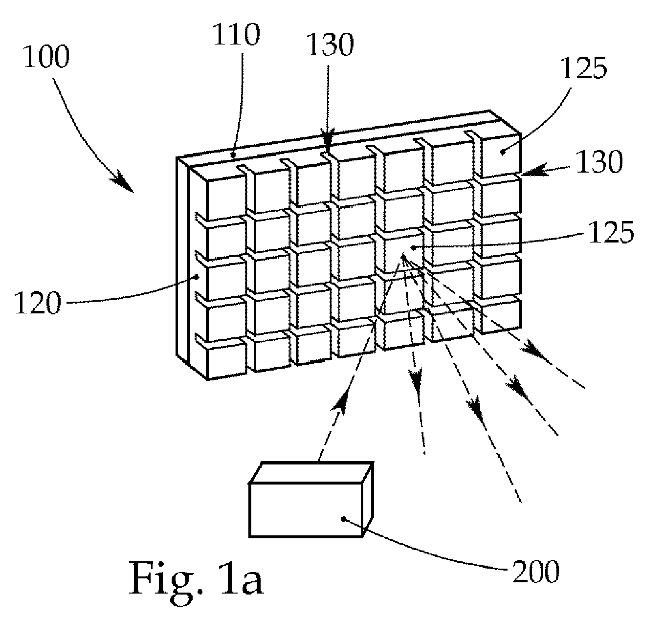
- Fig. 1a and Fig. 1b show a light module for a motor vehicle headlamp, which light module comprises a conversion means 100 and a lighting means 200 which is designed as a laser device, preferably as a laser diode.
- the conversion means 100 has a phosphor 120 arranged on a carrier layer 110 , which has a multiplicity of conversion segments 125 which are formed by depressions 130 in the phosphor 120 , wherein the laser device 200 is set up to excite the conversion segments 125 into a light emission with a wavelength conversion ,
- incident laser beams of the laser device to the phosphor 120 having conversion means 100 and stimulate the phosphor for photoluminescence.
- light is emitted in a different wavelength or wavelength ranges from the light of the irradiating laser device 200 .
- the light output of the conversion means 100 or the conversion segments 125 essentially has characteristics of a Lambertian radiator.
- Fig. 1 For this purpose, exemplary light beams are shown.
- the material for the phosphor 120 may be selected from the group YAG: Gd, YAG-Ce, Y 2 O 3 -La 2 O 3 , MgAl 2 O 4 , Ca 2 Si 5 N 8 , Sr 2 Si 5 N 8 or Ba 2 Si 5 N 8 .
- the recesses 130 are formed as a continuous structure, for example in a grid, and filled with a filler 300 , which in Fig. 3 can be seen more clearly.
- a filler for example, a ceramic material may be provided.
- the filler 300 in the recesses 130 prevents possible crosstalk of light beams to adjacent conversion segments 125 , which also increases the contrast and at the same time the mechanical stability of the overall structure.
- Fig. 2 shows an outline of the exemplary conversion means Fig. 1a and Fig. 1b ,
- Fig. 3 is a detailed view of a section through the conversion means from the previous figures to see, between the support layer 110 and the phosphor 120, a reflective intermediate layer 500 is disposed.
- an electrically conductive and optically reflecting layer 400 is arranged between the filling means 300 and the depressions 130 or the walls of the depressions 130 in regions.
- region-wise means that the electrically conductive layer 400 does not have to completely cover the depressions 130 or the walls of the depressions 130 , for example, also in FIG Fig. 3 is shown.
- Such an electrically conductive layer 400 in the recesses 130 can be used to check the functionality of the conversion means 100 , wherein at a fraction of the phosphor 120 and the conversion segments 125 and the electrically conductive layer 400 is interrupted, whereby, for example, changes the electrical resistance.
- the electrically conductive layer 400 may, for example, be formed from metal, preferably from Ag, Cu, Pt, Pd, Ni, Al or mixtures thereof.
- Such an electrically conductive layer 400 in the recesses 130 can be used to check the functionality of the conversion means 100 , wherein in the event of breakage of the phosphor 120 or of the conversion segments 125 , the electrically conductive layer is also used Layer 400 is interrupted, whereby, for example, changes the electrical resistance.
- Fig. 4 For this purpose, an exemplary measuring arrangement of two measuring devices 600 is shown, which are set up to measure the resistance of the at least one electrically conductive layer 400 . By such a resistance measurement can be determined whether a fraction of the phosphor 120 per se or the conversion segments 125 has occurred.
- a transversely induced voltage is measured.
- a voltage is applied to two opposite electrodes, whereby a transverse voltage is measured at two electrodes rotated by 90 ° to the previous electrodes and this transverse voltage is equal to zero with absolute symmetry. If this symmetry is disturbed, for example by a scratch or similar damage to the surface, one measures a non-zero transverse stress.
Landscapes
- Engineering & Computer Science (AREA)
- General Engineering & Computer Science (AREA)
- Physics & Mathematics (AREA)
- Optics & Photonics (AREA)
- Led Device Packages (AREA)
- Non-Portable Lighting Devices Or Systems Thereof (AREA)
- Luminescent Compositions (AREA)
- Lighting Device Outwards From Vehicle And Optical Signal (AREA)
Abstract
Description
- Die Erfindung betrifft ein Lichtmodul für einen Kraftfahrzeugscheinwerfer, welches Lichtmodul ein Konversionsmittel und ein Leuchtmittel umfasst, welches Konversionsmittel einen auf einer Trägerschicht angeordneten Leuchtstoff aufweist, wobei der Leuchtstoff eine Vielzahl von Konversionssegmenten aufweist, welche durch Vertiefungen in dem Leuchtstoff gebildet sind, wobei das Leuchtmittel eingerichtet ist, die Konversionssegmente zu einer Lichtemission mit einer Wellenlängenkonversion anzuregen.
- Die Erfindung betrifft ebenso einen Kraftfahrzeugscheinwerfer mit zumindest einem erfindungsgemäßen Lichtmodul.
- Da beispielsweise Lasereinrichtungen in der Regel kohärentes, monochromatisches Licht bzw. Licht in einem engen Wellenlängenbereich abstrahlen, aber bei einem Kraftfahrzeugscheinwerfer im Allgemeinen für das abgestrahlte Licht weißes Mischlicht bevorzugt bzw. gesetzlich vorgeschrieben ist, sind in Abstrahlrichtung der Lasereinrichtung sogenannte Konversionsmittel zur Umwandlung von im Wesentlichen monochromatischem Licht in weißes bzw. polychromatisches Licht angeordnet, wobei unter "weißes Licht" Licht einer solchen Spektralzusammensetzung verstanden wird, welches beim Menschen den Farbeindruck "weiß" hervorruft. Dieses Konversionsmittel ist zum Beispiel in Form eines oder mehrerer Photolumineszenzkonverter bzw. einem Leuchtstoff ausgebildet, wobei einfallende Laserstrahlen der Lasereinrichtung auf das in der Regel Leuchtstoff aufweisende Konversionsmittel auftreffen und diesen Leuchtstoff bzw. Photolumineszenzfarbstoff zur Photolumineszenz anregen, und dabei Licht in einer dem Licht der einstrahlenden Lasereinrichtung verschiedenen Wellenlänge bzw. Wellenlängenbereiche abgegeben wird. Die Lichtabgabe des Konversionsmittels weist dabei im Wesentlichen Charakteristiken eines Lambert'schen Strahlers auf.
- Bei Lichtkonversionselementen wird zwischen reflektiven und transmissiven Konversionsmitteln unterschieden.
- Die Begriffe "reflektiv" und "transmissiv" beziehen sich hierbei auf den Blauanteil des konvertierten weißen Lichts. Bei einem transmissiven Aufbau ist die Hauptausbreitungsrichtung des Blaulichtanteils nach dem Durchtritt durch das Konvertervolumen bzw. Konversionsmittels im Wesentlichen gleichgerichtet zur Ausbreitungsrichtung des Ausgangslaserstrahls. Bei einem reflektiven Aufbau wird der Laserstrahl an einer dem Konversionsmittel zurechenbaren Grenzfläche reflektiert bzw. umgelenkt, sodass der Blaulichtanteil eine andere Ausbreitungsrichtung aufweist als der Laserstrahl, welcher in der Regel als blauer Laserstrahl ausgeführt ist.
- Aus dem Stand der Technik sind Konversionsmaterialien bzw. Leuchtstoffe beispielsweise aus der Klasse dotierter Verbindungen mit einer Granatstruktur, wie Ce-dotiertes Yttrium-Aluminium-Granat (Ce:YAG) bekannt, wobei eine Vielfalt an in der Größe unterschiedlich ausgeprägten Partikeln in einer bindenden Matrix konfektioniert sind, welche auf einem Träger mit hoher thermischer Leitfähigkeit, beispielsweise aus Saphir, fixiert ist. Bei einer Konvertierung eines intensiven, fokussierten Laserstrahls, wie beispielsweise bei scannenden Kraftfahrzeugscheinwerfern eingesetzt wird, ergeben sich Limitierungen bezüglich des Thermomanagements als auch der erzielbaren Auflösung bzw. des Kontrastverhältnisses eines konvertierten Leuchtpunktes, da durch eine vielfache Streuung an konvertierenden Partikeln eine Aufweitung des eingebrachten, fein fokussierten Laserstrahles erfolgt.
- Derselbe Effekt tritt auch bei matrixlosen, gesinterten Keramikkonversionsmitteln auf, bei welchen einzelne Kristallite bzw. Gefügekörner im Allgemeinen oder Poren als Streuzentren wirken.
- Der Begriff "Gefüge" kennzeichnet die Beschaffenheit der Gesamtheit jener Teilvolumina, von denen jedes hinsichtlich seiner Zusammensetzung und der räumlichen Anordnung seiner Bausteine in Bezug auf ein in den Werkstoff gelegtes, ortsfestes Achsenkreuz in erster Näherung homogen ist.
- Das Gefüge ist durch Art, Form, Größe, Verteilung und Orientierung der Gefügebestandteile charakterisiert.
- Weiters können auch die Strukturen mehrphasig ausgebildeter Keramiken, beispielsweise Ce:YAG gemeinsam mit Korund, als Streuzentren fungieren.
- Jedoch ist ohne weitere Maßnahmen zur Eindämmung einer lateralen Leuchtpunktaufweitung der Einsatz von rasternd abbildenden Systemen bzw. Kraftfahrzeugscheinwerfern nicht möglich.
- Eine erfolgversprechende Maßnahme zur Reduktion der lateralen Leuchtpunktaufweitung, insbesondere in reflektiven Systemen, besteht in einer gezielten Unterteilung des Leuchtstoffes in einzelne Segmente, ausgehend von einer ursprünglich kompakten Basiskeramik.
- Solche Segmente - im weiteren Verlauf Konversionssegmente genannt - werden durch in den Leuchtstoff eingebrachte Vertiefungen erzeugt.
- Ein Nachteil dieser Strukturierung ist jedoch, dass die mechanische Festigkeit und Gesamtintegrität, beispielsweise durch Mikrorisse oder Ausbrüche in den einzelnen Segmenten, geschwächt wird.
- Weiters ist in Hinblick auf einen sicheren Laser-Einsatz im Stand der Technik, trotz eines erhöhten Ausfallsrisikos der einzelnen Segmente, kein Ansatz zur intrinsischen Überwachung der Funktionalität des Konversionsmittels vorgesehen.
- Es ist eine Aufgabe der Erfindung die Formstabilität eines Konversionsmittels eines Lichtmoduls zu verbessern.
- Diese Aufgabe wird dadurch gelöst, dass die Vertiefungen als zusammenhängende Struktur ausgebildet sind und mit einem Füllmittel befüllt sind.
- Dadurch wird einerseits die Kontrastfähigkeit als auch die mechanische Stabilität des Konversionsmittels bzw. des Leuchtstoffes erhöht.
- Durch eine unterschiedliche Füllhöhe des in den Vertiefungen angeordneten Füllmittels können die Kontrasteigenschaften lokal angepasst werden.
- Durch das Auffüllen der Vertiefungen mit dem Füllmittel ist es möglich, die Größe der einzelnen Konversionssegmente zu verkleinern und dadurch die Auflösung zu erhöhen, da durch das Füllmittel die gesamte Stabilität des Konversionsmittels bzw. Leuchtstoffes erhöht wird.
- Weiters wird durch das Füllmittel in den Vertiefungen ein mögliches Übersprechen von Lichtstrahlen auf ein benachbartes Konversionssegment verhindert, was ebenfalls den Kontrast erhöht.
- Weiters können im Zuge eines Auffüllvorgangs der Vertiefungen mittels dem Füllmittel Mikrorisse in der Keramik, welche durch den Strukturierungsprozess entstehen, wieder aufgefüllt bzw. versiegelt werden, was zusätzlich zur Stabilität der Gesamtstruktur beiträgt.
- Als Füllmaterial kann beispielsweise ein keramischer Stoff vorgesehen sein.
- Als Füllmaterial können Isolations-/Keramikschichten unter Verwendung von Alkoxid-Sol/Gel Prozessen zur Erzielung von Alumina/Silica/Mullit/Zirconia/Rutil Abscheidungen, welche auch untereinander gemischt und mehr oder weniger ausgeprägt kristallin bzw. stöchiometrisch exakt ausgeprägt sein können, aufgebracht werden, wobei teilweise vorkonfektionierte Sole/Gele (Böhmit AlO(OH); Sasol Disperal®; Akzo Nobel Levasil®, ...) verwendet werden können. Durch Anpassung der allgemeinen Reaktionsparameter, der Oberflächenspannung und/oder der Trocknungs- bzw. Ausheizcharakteristik kann insbesondere die Porosität kontrolliert werden, um materialspezifische Eigenschaften hinsichtlich der thermischen Leitfähgkeit, der mechanischen Festigkeit oder der thermischen Ausdehnungskoeffizienten anzupassen.
- Der verwendete Leuchtstoff kann beispielsweise polykristallin gesintert oder gewachsen bzw. aus einer Schmelze gezogen sein. Ferner ist ein teilamorphes Gefüge bzw. auch einkristalline Scheiben mit nachträgliche eingebrachten Strukturen bzw. Störstellen als Streuzentren möglich.
- Die zusammenhängende Struktur der Vertiefungen wird mittels einem mechanischen Verfahren erreicht, beispielsweise durch Sägen, Laserablation bzw. Focused Ion Beam. Die so erhaltenen Konversionssegmente - auch Pixel genannt - können eine Breite von ca. 50 µm und einen Abstand zueinander von ca. 10 µm aufweisen. Die Vertiefungen können hierbei eine Tiefe von bis zu ca. 100 µm aufweisen.
- Es kann vorgesehen sein, dass die Vertiefungen zumindest bereichsweise zumindest eine elektrisch leitfähige und/oder optisch reflektierende Schicht aufweisen, d.h. dass zwischen dem Füllmittel und den Vertiefungen zumindest bereichsweise zumindest eine elektrisch leitfähige und/oder optisch reflektierende Schicht angeordnet ist.
- Die zumindest eine elektrisch leitfähige und/oder optisch reflektierende Schicht ist beispielsweise auf der Oberfläche der Vertiefungen angeordnet. Unter "Oberfläche" sind hierbei die Wände bzw. der Boden der Vertiefungen gemeint und nicht die Oberfläche, welche die Oberfläche der Konversionssegmente bildet.
- Diese Schicht kann vorzugsweise aus Lösungen von Metallsalzen stromlos abgeschieden werden. Für eine Schichtabscheidung in den Vertiefungen können die Lösungen bezüglich Oberflächenspannung, Viskosität, Konzentration und Reaktions-Trocknungsbedingungen angepasst werden, sodass die Lösungen einerseits bevorzugt durch Kapillarkräfte getrieben in die Vertiefungen gelangen und dort die Wände als Keimzonen nützen, und andererseits sich ein guter Spiegel ausbildet und möglichst keine Abscheidungen auf der Licht emittierenden Oberseite der einzelnen Konversionssegmenten erfolgt, welche in nachfolgenden Bearbeitungsschritten entfernt werden müssten.
- Eine solche elektrisch leitfähige Schicht in den Vertiefungen kann zur Überprüfung der Funktionsfähigkeit des Konversionsmittels verwendet werden, wobei bei einem Bruch des Leuchtstoffes bzw. der Konversionssegmente auch die elektrisch leitfähige Schicht unterbrochen wird, wodurch sich beispielsweise der elektrische Widerstand ändert.
- Mit Vorteil kann vorgesehen sein, wenn das Lichtmodul ferner zumindest eine Messeinrichtung aufweist, welche eingerichtet ist, den Widerstand der zumindest einen elektrisch leitfähigen Schicht zu messen, wobei sich der Widerstand bei einem Bruch der zumindest einen elektrisch leitfähigen Schicht ändert. Durch eine solche Widerstandsmessung kann demnach festgestellt werden, ob ein Bruch des Leuchtstoffes an sich bzw. den Konversionssegmenten aufgetreten ist.
- Durch die zumindest eine elektrisch leitfähige Schicht bzw. der Widerstandsmessung der zumindest einen elektrisch leitfähige Schicht ist eine intrinsische Überwachung der Funktionalität des Konversionsmittels gegeben.
- Eine Licht reflektierende Schicht in den Vertiefungen kann dazu dienen, ein optisches Übersprechen zwischen den jeweiligen Konversionssegmenten zu vermeiden, um so den Kontrast zu verbessern.
- Vorteilhafterweise kann zusätzlich zwischen dem Konversionselement und der Trägerschicht eine reflektierende Zwischenschicht angeordnet sein.
- Es kann günstig sein, wenn das Material für den Leuchtstoff aus der Gruppe YAG:Gd, YAG-Ce, Y2O3-La2O3, MgAl2O4, Ca2Si5N8, Sr2Si5N8 oder Ba2Si5N8 gewählt ist.
- Es kann vorgesehen sein, dass die zumindest eine Schicht aus Metall gebildet ist, vorzugsweise aus Ag, Cu, Pt, Pd, Ni oder Al.
- Es sei angemerkt, dass alle Kombinationen für das Material des Leuchtstoffes und der zumindest einen elektrisch leitfähigen und/oder optisch reflektierenden Schicht möglich sind.
- In einer vorteilhaften Ausführungsform kann das Leuchtmittel als Lasereinrichtung ausgebildet sein, vorzugsweise als Laserdiode.
- Vorteilhafterweise können die von dem Leuchtmittel emittierenden Lichtstrahlen über ein Ablenkmittel, beispielsweise einem beweglichen Spiegel, auf die Konversionssegmente lenkbar sein.
- Die von dem Leuchtmittel, vorzugsweise zumindest eine Laserdiode, emittierten Lichtstrahlen können über das Ablenkmittel, vorzugsweise einem mikromechanischen Spiegel, abgelenkt werden, um unterschiedliche Bereiche des Konversionsmittels auszuleuchten.
- Es kann vorgesehen sein, dass die Trägerschicht aus einem thermisch leitfähigen Material gebildet ist, beispielsweise aus Saphir.
- Nachfolgend wird die Erfindung anhand von beispielhaften Zeichnungen näher erläutert. Hierbei zeigt
-
Fig. 1a ein beispielhaftes Lichtmodul mit einem Konversionsmittel, welches eine Vielzahl von durch Vertiefungen ausgebildete Konversionssegmente aufweist, und einem als Lasereinrichtung ausgebildetes Leuchtmittel in einer perspektivischen Ansicht, -
Fig. 1b das Lichtmodul ausFig. 1a in einer Draufsicht, wobei ein Füllmittel in den Vertiefungen zu sehen ist, -
Fig. 2 ein Konversionsmittel in einem Aufriss, -
Fig. 3 eine Detailansicht von einem Schnitt durch ein beispielhaftes Konversionsmittel, wobei zwischen dem Füllmittel und den Vertiefungen eine elektrisch leitfähige Schicht angeordnet ist, und -
Fig. 4 eine beispielhafte Messanordnung mit zwei Messeinrichtungen zur Widerstandsmessung der elektrisch leitfähigen Schicht. -
Fig. 1a und Fig. 1b zeigen ein Lichtmodul für einen Kraftfahrzeugscheinwerfer, welches Lichtmodul ein Konversionsmittel 100 und ein Leuchtmittel 200, welches als Lasereinrichtung, vorzugsweise als Laserdiode, ausgebildet ist, umfasst. Das Konversionsmittel 100 weist einen auf einer Trägerschicht 110 angeordneten Leuchtstoff 120 auf, welcher eine Vielzahl von Konversionssegmenten 125 aufweist, welche durch Vertiefungen 130 in dem Leuchtstoff 120 gebildet sind, wobei die Lasereinrichtung 200 eingerichtet ist, die Konversionssegmente 125 zu einer Lichtemission mit einer Wellenlängenkonversion anzuregen. - Hierbei treffen einfallende Laserstrahlen der Lasereinrichtung auf das Leuchtstoff 120 aufweisende Konversionsmittel 100 auf und regen den Leuchtstoff zur Photolumineszenz an. Dabei wird Licht in einer dem Licht der einstrahlenden Lasereinrichtung 200 verschiedenen Wellenlänge bzw. Wellenlängenbereiche abgegeben. Die Lichtabgabe des Konversionsmittels 100 bzw. der Konversionssegmente 125 weist dabei im Wesentlichen Charakteristiken eines Lambert'schen Strahlers auf. In
Fig. 1 sind hierzu beispielhafte Lichtstrahlen eingezeichnet. - Das Material für den Leuchtstoff 120 kann gewählt sein aus der Gruppe YAG:Gd, YAG-Ce, Y2O3-La2O3, MgAl2O4, Ca2Si5N8, Sr2Si5N8 oder Ba2Si5N8.
- Die Vertiefungen 130 sind als zusammenhängende Struktur ausgebildet, beispielsweise in einem Raster, und mit einem Füllmittel 300 befüllt, welches in
Fig. 3 deutlicher zu sehen ist. Als Füllmaterial kann beispielsweise ein keramischer Stoff vorgesehen sein. - Durch das Füllmittel 300 in den Vertiefungen 130 wird ein mögliches Übersprechen von Lichtstrahlen auf benachbarte Konversionssegmente 125 verhindert, was ebenfalls den Kontrast und gleichzeitig die mechanische Stabilität der Gesamtstruktur erhöht.
-
Fig. 2 zeigt einen Aufriss des beispielhaften Konversionsmittels ausFig. 1a und Fig. 1b . - In
Fig. 3 ist eine Detailansicht eines Schnitts durch das Konversionsmittel aus den vorherigen Figuren zu sehen, wobei zwischen der Trägerschicht 110 und dem Leuchtstoff 120 eine reflektierende Zwischenschicht 500 angeordnet ist. - Ferner ist zwischen dem Füllmittel 300 und den Vertiefungen 130 bzw. den Wänden der Vertiefungen 130 bereichsweise eine elektrisch leitfähige und optisch reflektierende Schicht 400 angeordnet. Unter "bereichsweise" ist hierbei zu verstehen, dass die elektrisch leitfähige Schicht 400 die Vertiefungen 130 bzw. die Wände der Vertiefungen 130 nicht zur Gänze bedecken muss, wie beispielsweise auch in
Fig. 3 dargestellt ist. - Eine solche elektrisch leitfähige Schicht 400 in den Vertiefungen 130 kann zur Überprüfung der Funktionsfähigkeit des Konversionsmittels 100 verwendet werden, wobei bei einem Bruch des Leuchtstoffes 120 bzw. der Konversionssegmente 125 auch die elektrisch leitfähige Schicht 400 unterbrochen wird, wodurch sich beispielsweise der elektrische Widerstand ändert.
- Die elektrisch leitfähige Schicht 400 kann beispielsweise aus Metall gebildet sein, vorzugsweise aus Ag, Cu, Pt, Pd, Ni, Al oder Mischungen daraus.
- Eine solche elektrisch leitfähige Schicht 400 in den Vertiefungen 130 kann zur Überprüfung der Funktionsfähigkeit des Konversionsmittels 100 verwendet werden, wobei bei einem Bruch des Leuchtstoffes 120 bzw. der Konversionssegmente 125 auch die elektrisch leitfähige Schicht 400 unterbrochen wird, wodurch sich beispielsweise der elektrische Widerstand ändert.
- In
Fig. 4 ist hierzu eine beispielhafte Messanordnung aus zwei Messeinrichtungen 600 gezeigt, welche eingerichtet sind, den Widerstand der zumindest einen elektrisch leitfähigen Schicht 400 zu messen. Durch eine solche Widerstandsmessung kann festgestellt werden, ob ein Bruch des Leuchtstoffes 120 an sich bzw. den Konversionssegmenten 125 aufgetreten ist. - Es kann auch vorgesehen sein, dass statt der Widerstandsmessung eine querinduzierte Spannung gemessen wird. Hierzu legt man an zwei gegenüberliegende Elektroden eine Spannung an, wobei eine Querspannung an zwei um 90° zu den vorigen Elektroden gedrehten Elektroden gemessen wird und diese Querspannung bei absoluter Symmetrie gleich Null ist. Wird diese Symmetrie zum Beispiel durch einen Kratzer oder ähnliche Beschädigungen an der Oberfläche gestört, misst man eine von Null verschiedene Querspannung.
BEZUGSZEICHENLISTE Konversionsmittel 100 Trägerschicht 110 Leuchtstoff 120 Konversionssegment 125 Vertiefungen 130 Leuchtmittel 200 Füllmittel 300 Schicht 400 Zwischenschicht 500
Claims (10)
- Lichtmodul für einen Kraftfahrzeugscheinwerfer, welches Lichtmodul ein Konversionsmittel (100) und ein Leuchtmittel (200) umfasst, welches Konversionsmittel (100) einen auf einer Trägerschicht (110) angeordneten Leuchtstoff (120) aufweist, wobei der Leuchtstoff (120) eine Vielzahl von Konversionssegmenten (125) aufweist, welche durch Vertiefungen (130) in dem Leuchtstoff (120) gebildet sind, wobei das Leuchtmittel (200) eingerichtet ist, die Konversionssegmente (125) mittels von dem Leuchtmittel (200) emittierbaren Lichtstrahlen zu einer Lichtemission mit einer Wellenlängenkonversion anzuregen,
dadurch gekennzeichnet, dass
die Vertiefungen (130) als zusammenhängende Struktur ausgebildet sind und mit einem Füllmittel (300) befüllt sind. - Lichtmodul nach Anspruch 1, dadurch gekennzeichnet, dass die Vertiefungen (130) zumindest bereichsweise zumindest eine elektrisch leitfähige und/oder optisch reflektierende Schicht (400) aufweisen.
- Lichtmodul nach Anspruch 1 oder 2, dadurch gekennzeichnet, dass zwischen dem Leuchtstoff (120) und der Trägerschicht (110) eine Licht reflektierende und/oder elektrisch leitfähige Zwischenschicht (500), beispielsweise aus Metall, angeordnet ist.
- Lichtmodul nach einem der Ansprüche 1 bis 3, dadurch gekennzeichnet, dass das Material für den Leuchtstoff (120) gewählt ist aus der Gruppe YAG:Gd, YAG-Ce, Y2O3-La2O3, MgAl2O4, Ca2Si5N8, Sr2Si5N8 oder Ba2Si5N8.
- Lichtmodul nach einem der Ansprüche 2 bis 4, dadurch gekennzeichnet, dass die zumindest eine elektrisch leitfähige und/oder optisch reflektierende Schicht (400) aus Metall gebildet ist, vorzugsweise aus Ag, Cu, Pt, Pd, Ni oder Al.
- Lichtmodul nach einem der Ansprüche 1 bis 5, dadurch gekennzeichnet, dass das Leuchtmittel (200) als Lasereinrichtung ausgebildet ist, vorzugsweise als Laserdiode.
- Lichtmodul nach einem der Ansprüche 1 bis 6, dadurch gekennzeichnet, dass die Trägerschicht (110) aus einem thermisch leitfähigen Material gebildet ist, beispielsweise aus Saphir.
- Lichtmodul nach einem der Ansprüche 2 bis 6, dadurch gekennzeichnet, dass das Lichtmodul ferner zumindest eine Messeinrichtung (600) aufweist, welche eingerichtet ist, den Widerstand der zumindest einen elektrisch leitfähigen Schicht (400) zu messen.
- Lichtmodul nach einem der Ansprüche 1 bis 8, dadurch gekennzeichnet, dass das Füllmittel (300) aus einem keramischen Material gebildet ist.
- Kraftfahrzeugscheinwerfer mit zumindest einem Lichtmodul gemäß einem der Ansprüche 1 bis 9.
Priority Applications (3)
| Application Number | Priority Date | Filing Date | Title |
|---|---|---|---|
| EP18162863.7A EP3543596B1 (de) | 2018-03-20 | 2018-03-20 | Lichtmodul für einen kraftfahrzeugscheinwerfer |
| KR1020190030501A KR102155540B1 (ko) | 2018-03-20 | 2019-03-18 | 자동차 헤드램프용 광 모듈 |
| CN201910212544.7A CN110307516B (zh) | 2018-03-20 | 2019-03-20 | 用于机动车大灯的光模块 |
Applications Claiming Priority (1)
| Application Number | Priority Date | Filing Date | Title |
|---|---|---|---|
| EP18162863.7A EP3543596B1 (de) | 2018-03-20 | 2018-03-20 | Lichtmodul für einen kraftfahrzeugscheinwerfer |
Publications (2)
| Publication Number | Publication Date |
|---|---|
| EP3543596A1 true EP3543596A1 (de) | 2019-09-25 |
| EP3543596B1 EP3543596B1 (de) | 2020-08-26 |
Family
ID=61731600
Family Applications (1)
| Application Number | Title | Priority Date | Filing Date |
|---|---|---|---|
| EP18162863.7A Active EP3543596B1 (de) | 2018-03-20 | 2018-03-20 | Lichtmodul für einen kraftfahrzeugscheinwerfer |
Country Status (3)
| Country | Link |
|---|---|
| EP (1) | EP3543596B1 (de) |
| KR (1) | KR102155540B1 (de) |
| CN (1) | CN110307516B (de) |
Cited By (1)
| Publication number | Priority date | Publication date | Assignee | Title |
|---|---|---|---|---|
| US12031715B2 (en) | 2021-01-26 | 2024-07-09 | Signify Holding, B.V. | Pixelated laser phosphor comprising ceramic phosphor tiles surrounded by phosphor particles in a medium |
Citations (5)
| Publication number | Priority date | Publication date | Assignee | Title |
|---|---|---|---|---|
| US20110249460A1 (en) * | 2010-04-08 | 2011-10-13 | Takuya Kushimoto | Vehicle headlight |
| US20120119638A1 (en) * | 2010-11-17 | 2012-05-17 | Sharp Kabushiki Kaisha | Light emitting element, light emitting device, and method for producing light emitting device |
| US20160348856A1 (en) * | 2015-05-25 | 2016-12-01 | Stanley Electric Co., Ltd. | Wavelength converting module and semiconductor light-emtting apparatus using the same |
| US20170184254A1 (en) * | 2015-12-25 | 2017-06-29 | Nichia Corporation | Wavelength conversion member and light source device having wavelength conversion member |
| US20170254489A1 (en) * | 2014-09-17 | 2017-09-07 | Koninklijke Philips N.V. | Lighting system |
Family Cites Families (4)
| Publication number | Priority date | Publication date | Assignee | Title |
|---|---|---|---|---|
| JP2010129615A (ja) * | 2008-11-25 | 2010-06-10 | Toshiba Lighting & Technology Corp | 発光装置及び照明装置 |
| JP2013102078A (ja) * | 2011-11-09 | 2013-05-23 | Stanley Electric Co Ltd | 光源装置および照明装置 |
| JP6248743B2 (ja) * | 2014-03-27 | 2017-12-20 | ウシオ電機株式会社 | 蛍光光源装置 |
| US10174931B2 (en) * | 2015-06-03 | 2019-01-08 | Apple Inc. | Integrated optical modules with enhanced reliability and integrity |
-
2018
- 2018-03-20 EP EP18162863.7A patent/EP3543596B1/de active Active
-
2019
- 2019-03-18 KR KR1020190030501A patent/KR102155540B1/ko not_active Expired - Fee Related
- 2019-03-20 CN CN201910212544.7A patent/CN110307516B/zh active Active
Patent Citations (5)
| Publication number | Priority date | Publication date | Assignee | Title |
|---|---|---|---|---|
| US20110249460A1 (en) * | 2010-04-08 | 2011-10-13 | Takuya Kushimoto | Vehicle headlight |
| US20120119638A1 (en) * | 2010-11-17 | 2012-05-17 | Sharp Kabushiki Kaisha | Light emitting element, light emitting device, and method for producing light emitting device |
| US20170254489A1 (en) * | 2014-09-17 | 2017-09-07 | Koninklijke Philips N.V. | Lighting system |
| US20160348856A1 (en) * | 2015-05-25 | 2016-12-01 | Stanley Electric Co., Ltd. | Wavelength converting module and semiconductor light-emtting apparatus using the same |
| US20170184254A1 (en) * | 2015-12-25 | 2017-06-29 | Nichia Corporation | Wavelength conversion member and light source device having wavelength conversion member |
Cited By (1)
| Publication number | Priority date | Publication date | Assignee | Title |
|---|---|---|---|---|
| US12031715B2 (en) | 2021-01-26 | 2024-07-09 | Signify Holding, B.V. | Pixelated laser phosphor comprising ceramic phosphor tiles surrounded by phosphor particles in a medium |
Also Published As
| Publication number | Publication date |
|---|---|
| KR102155540B1 (ko) | 2020-09-15 |
| KR20190110451A (ko) | 2019-09-30 |
| CN110307516A (zh) | 2019-10-08 |
| CN110307516B (zh) | 2022-01-18 |
| EP3543596B1 (de) | 2020-08-26 |
Similar Documents
| Publication | Publication Date | Title |
|---|---|---|
| DE112013002508B4 (de) | Wellenlängen-Umwandlungselement, Verfahren zu seiner Herstellung und LED-Element und Laserlicht emittierendes Halbleiterbauteil, die das Wellenlängen-Umwandlungselement verwenden | |
| EP1982360B1 (de) | Lumineszenzdioden-bauelement mit gehäuse | |
| EP1771891B1 (de) | Lichtemittierendes bauelement und leuchtmodul | |
| DE69702929T4 (de) | Lichtemittierende vorrichtung und anzeigevorrichtung | |
| DE102008050643B4 (de) | Leuchtmittel | |
| EP2223337B1 (de) | Optoelektronisches bauelement und herstellungsverfahren für ein optoelektronisches bauelement | |
| DE102016104616B4 (de) | Halbleiterlichtquelle | |
| WO2012156514A1 (de) | Optoelektronischer halbleiterchip, optoelektronisches halbleiterbauelement und verfahren zur herstellung eines optoelektronischen halbleiterbauelements | |
| DE102010051286A1 (de) | Optoelektronischer Halbleiterchip und Verfahren zu dessen Herstellung | |
| DE102011113962B4 (de) | Verfahren zur Herstellung eines keramischen Konversionselements | |
| WO2019145422A9 (de) | Optoelektronischer halbleiterchip, optoelektronisches bauelement und dessen verfahren zur herstellung | |
| DE102008025923A1 (de) | Strahlungsemittierende Vorrichtung | |
| DE102015101573A1 (de) | Konversionselement und optoelektronisches Bauelement | |
| DE102013107227A1 (de) | Konversionselement mit Trennstruktur | |
| WO2013029862A1 (de) | Verfahren zur herstellung einer leuchtdiode und leuchtdiode | |
| DE112018007862T5 (de) | Leuchtstoffelement und Beleuchtungsvorrichtung | |
| EP1905287B1 (de) | Gehäuse für ein elektromagnetische strahlung emittierendes optoelektronisches bauelement, elektromagnetische strahlung emittierendes bauelement und verfahren zum herstellen eines gehäuses oder eines bauelements | |
| EP3543596B1 (de) | Lichtmodul für einen kraftfahrzeugscheinwerfer | |
| DE102004052456B4 (de) | Strahlungsemittierendes Bauelement und Verfahren zu dessen Herstellung | |
| DE112018006802B4 (de) | Element zum Erzeugen von weißem Licht und Beleuchtungsvorrichtung | |
| DE102018105884A1 (de) | Optoelektronisches bauelement mit einer vielzahl licht emittierender bereiche und verfahren zur herstellung des optoelektronischen bauelements | |
| WO2015185296A1 (de) | Lichtkonversionsvorrichtung und verfahren zum seiner herstellung | |
| DE102017118749A1 (de) | Lichtemittierende vorrichtung, beleuchtungsvorrichtung und verfahren zur herstellung einer lichtemittierenden vorrichtung | |
| DE112022002217T5 (de) | Lichtemittierende Vorrichtung, Scheinwerfer und Fahrzeug mit einer solchen Vorrichtung | |
| DE102014107473A1 (de) | Konverterelement zur Konvertierung einer Wellenlänge, optoelektronisches Bauelement mit Konverterelement und Verfahren zum Herstellen eines Konverterelements |
Legal Events
| Date | Code | Title | Description |
|---|---|---|---|
| PUAI | Public reference made under article 153(3) epc to a published international application that has entered the european phase |
Free format text: ORIGINAL CODE: 0009012 |
|
| STAA | Information on the status of an ep patent application or granted ep patent |
Free format text: STATUS: THE APPLICATION HAS BEEN PUBLISHED |
|
| AK | Designated contracting states |
Kind code of ref document: A1 Designated state(s): AL AT BE BG CH CY CZ DE DK EE ES FI FR GB GR HR HU IE IS IT LI LT LU LV MC MK MT NL NO PL PT RO RS SE SI SK SM TR |
|
| AX | Request for extension of the european patent |
Extension state: BA ME |
|
| STAA | Information on the status of an ep patent application or granted ep patent |
Free format text: STATUS: REQUEST FOR EXAMINATION WAS MADE |
|
| 17P | Request for examination filed |
Effective date: 20200302 |
|
| RBV | Designated contracting states (corrected) |
Designated state(s): AL AT BE BG CH CY CZ DE DK EE ES FI FR GB GR HR HU IE IS IT LI LT LU LV MC MK MT NL NO PL PT RO RS SE SI SK SM TR |
|
| GRAP | Despatch of communication of intention to grant a patent |
Free format text: ORIGINAL CODE: EPIDOSNIGR1 |
|
| STAA | Information on the status of an ep patent application or granted ep patent |
Free format text: STATUS: GRANT OF PATENT IS INTENDED |
|
| GRAS | Grant fee paid |
Free format text: ORIGINAL CODE: EPIDOSNIGR3 |
|
| GRAA | (expected) grant |
Free format text: ORIGINAL CODE: 0009210 |
|
| STAA | Information on the status of an ep patent application or granted ep patent |
Free format text: STATUS: THE PATENT HAS BEEN GRANTED |
|
| INTG | Intention to grant announced |
Effective date: 20200708 |
|
| AK | Designated contracting states |
Kind code of ref document: B1 Designated state(s): AL AT BE BG CH CY CZ DE DK EE ES FI FR GB GR HR HU IE IS IT LI LT LU LV MC MK MT NL NO PL PT RO RS SE SI SK SM TR |
|
| REG | Reference to a national code |
Ref country code: GB Ref legal event code: FG4D Free format text: NOT ENGLISH |
|
| REG | Reference to a national code |
Ref country code: CH Ref legal event code: EP |
|
| REG | Reference to a national code |
Ref country code: DE Ref legal event code: R096 Ref document number: 502018002259 Country of ref document: DE |
|
| REG | Reference to a national code |
Ref country code: AT Ref legal event code: REF Ref document number: 1306726 Country of ref document: AT Kind code of ref document: T Effective date: 20200915 |
|
| REG | Reference to a national code |
Ref country code: IE Ref legal event code: FG4D Free format text: LANGUAGE OF EP DOCUMENT: GERMAN |
|
| REG | Reference to a national code |
Ref country code: LT Ref legal event code: MG4D |
|
| PG25 | Lapsed in a contracting state [announced via postgrant information from national office to epo] |
Ref country code: LT Free format text: LAPSE BECAUSE OF FAILURE TO SUBMIT A TRANSLATION OF THE DESCRIPTION OR TO PAY THE FEE WITHIN THE PRESCRIBED TIME-LIMIT Effective date: 20200826 Ref country code: HR Free format text: LAPSE BECAUSE OF FAILURE TO SUBMIT A TRANSLATION OF THE DESCRIPTION OR TO PAY THE FEE WITHIN THE PRESCRIBED TIME-LIMIT Effective date: 20200826 Ref country code: NO Free format text: LAPSE BECAUSE OF FAILURE TO SUBMIT A TRANSLATION OF THE DESCRIPTION OR TO PAY THE FEE WITHIN THE PRESCRIBED TIME-LIMIT Effective date: 20201126 Ref country code: GR Free format text: LAPSE BECAUSE OF FAILURE TO SUBMIT A TRANSLATION OF THE DESCRIPTION OR TO PAY THE FEE WITHIN THE PRESCRIBED TIME-LIMIT Effective date: 20201127 Ref country code: FI Free format text: LAPSE BECAUSE OF FAILURE TO SUBMIT A TRANSLATION OF THE DESCRIPTION OR TO PAY THE FEE WITHIN THE PRESCRIBED TIME-LIMIT Effective date: 20200826 Ref country code: SE Free format text: LAPSE BECAUSE OF FAILURE TO SUBMIT A TRANSLATION OF THE DESCRIPTION OR TO PAY THE FEE WITHIN THE PRESCRIBED TIME-LIMIT Effective date: 20200826 Ref country code: PT Free format text: LAPSE BECAUSE OF FAILURE TO SUBMIT A TRANSLATION OF THE DESCRIPTION OR TO PAY THE FEE WITHIN THE PRESCRIBED TIME-LIMIT Effective date: 20201228 Ref country code: BG Free format text: LAPSE BECAUSE OF FAILURE TO SUBMIT A TRANSLATION OF THE DESCRIPTION OR TO PAY THE FEE WITHIN THE PRESCRIBED TIME-LIMIT Effective date: 20201126 |
|
| REG | Reference to a national code |
Ref country code: NL Ref legal event code: MP Effective date: 20200826 |
|
| PG25 | Lapsed in a contracting state [announced via postgrant information from national office to epo] |
Ref country code: NL Free format text: LAPSE BECAUSE OF FAILURE TO SUBMIT A TRANSLATION OF THE DESCRIPTION OR TO PAY THE FEE WITHIN THE PRESCRIBED TIME-LIMIT Effective date: 20200826 Ref country code: PL Free format text: LAPSE BECAUSE OF FAILURE TO SUBMIT A TRANSLATION OF THE DESCRIPTION OR TO PAY THE FEE WITHIN THE PRESCRIBED TIME-LIMIT Effective date: 20200826 Ref country code: LV Free format text: LAPSE BECAUSE OF FAILURE TO SUBMIT A TRANSLATION OF THE DESCRIPTION OR TO PAY THE FEE WITHIN THE PRESCRIBED TIME-LIMIT Effective date: 20200826 Ref country code: RS Free format text: LAPSE BECAUSE OF FAILURE TO SUBMIT A TRANSLATION OF THE DESCRIPTION OR TO PAY THE FEE WITHIN THE PRESCRIBED TIME-LIMIT Effective date: 20200826 Ref country code: IS Free format text: LAPSE BECAUSE OF FAILURE TO SUBMIT A TRANSLATION OF THE DESCRIPTION OR TO PAY THE FEE WITHIN THE PRESCRIBED TIME-LIMIT Effective date: 20201226 |
|
| PG25 | Lapsed in a contracting state [announced via postgrant information from national office to epo] |
Ref country code: SM Free format text: LAPSE BECAUSE OF FAILURE TO SUBMIT A TRANSLATION OF THE DESCRIPTION OR TO PAY THE FEE WITHIN THE PRESCRIBED TIME-LIMIT Effective date: 20200826 Ref country code: RO Free format text: LAPSE BECAUSE OF FAILURE TO SUBMIT A TRANSLATION OF THE DESCRIPTION OR TO PAY THE FEE WITHIN THE PRESCRIBED TIME-LIMIT Effective date: 20200826 Ref country code: CZ Free format text: LAPSE BECAUSE OF FAILURE TO SUBMIT A TRANSLATION OF THE DESCRIPTION OR TO PAY THE FEE WITHIN THE PRESCRIBED TIME-LIMIT Effective date: 20200826 Ref country code: DK Free format text: LAPSE BECAUSE OF FAILURE TO SUBMIT A TRANSLATION OF THE DESCRIPTION OR TO PAY THE FEE WITHIN THE PRESCRIBED TIME-LIMIT Effective date: 20200826 Ref country code: EE Free format text: LAPSE BECAUSE OF FAILURE TO SUBMIT A TRANSLATION OF THE DESCRIPTION OR TO PAY THE FEE WITHIN THE PRESCRIBED TIME-LIMIT Effective date: 20200826 |
|
| REG | Reference to a national code |
Ref country code: DE Ref legal event code: R097 Ref document number: 502018002259 Country of ref document: DE |
|
| PG25 | Lapsed in a contracting state [announced via postgrant information from national office to epo] |
Ref country code: AL Free format text: LAPSE BECAUSE OF FAILURE TO SUBMIT A TRANSLATION OF THE DESCRIPTION OR TO PAY THE FEE WITHIN THE PRESCRIBED TIME-LIMIT Effective date: 20200826 Ref country code: ES Free format text: LAPSE BECAUSE OF FAILURE TO SUBMIT A TRANSLATION OF THE DESCRIPTION OR TO PAY THE FEE WITHIN THE PRESCRIBED TIME-LIMIT Effective date: 20200826 |
|
| PG25 | Lapsed in a contracting state [announced via postgrant information from national office to epo] |
Ref country code: SK Free format text: LAPSE BECAUSE OF FAILURE TO SUBMIT A TRANSLATION OF THE DESCRIPTION OR TO PAY THE FEE WITHIN THE PRESCRIBED TIME-LIMIT Effective date: 20200826 |
|
| PLBE | No opposition filed within time limit |
Free format text: ORIGINAL CODE: 0009261 |
|
| STAA | Information on the status of an ep patent application or granted ep patent |
Free format text: STATUS: NO OPPOSITION FILED WITHIN TIME LIMIT |
|
| PG25 | Lapsed in a contracting state [announced via postgrant information from national office to epo] |
Ref country code: IT Free format text: LAPSE BECAUSE OF FAILURE TO SUBMIT A TRANSLATION OF THE DESCRIPTION OR TO PAY THE FEE WITHIN THE PRESCRIBED TIME-LIMIT Effective date: 20200826 |
|
| 26N | No opposition filed |
Effective date: 20210527 |
|
| PG25 | Lapsed in a contracting state [announced via postgrant information from national office to epo] |
Ref country code: SI Free format text: LAPSE BECAUSE OF FAILURE TO SUBMIT A TRANSLATION OF THE DESCRIPTION OR TO PAY THE FEE WITHIN THE PRESCRIBED TIME-LIMIT Effective date: 20200826 |
|
| PG25 | Lapsed in a contracting state [announced via postgrant information from national office to epo] |
Ref country code: MC Free format text: LAPSE BECAUSE OF FAILURE TO SUBMIT A TRANSLATION OF THE DESCRIPTION OR TO PAY THE FEE WITHIN THE PRESCRIBED TIME-LIMIT Effective date: 20200826 |
|
| REG | Reference to a national code |
Ref country code: CH Ref legal event code: PL |
|
| REG | Reference to a national code |
Ref country code: BE Ref legal event code: MM Effective date: 20210331 |
|
| PG25 | Lapsed in a contracting state [announced via postgrant information from national office to epo] |
Ref country code: LU Free format text: LAPSE BECAUSE OF NON-PAYMENT OF DUE FEES Effective date: 20210320 Ref country code: IE Free format text: LAPSE BECAUSE OF NON-PAYMENT OF DUE FEES Effective date: 20210320 Ref country code: LI Free format text: LAPSE BECAUSE OF NON-PAYMENT OF DUE FEES Effective date: 20210331 Ref country code: CH Free format text: LAPSE BECAUSE OF NON-PAYMENT OF DUE FEES Effective date: 20210331 |
|
| PG25 | Lapsed in a contracting state [announced via postgrant information from national office to epo] |
Ref country code: BE Free format text: LAPSE BECAUSE OF NON-PAYMENT OF DUE FEES Effective date: 20210331 |
|
| GBPC | Gb: european patent ceased through non-payment of renewal fee |
Effective date: 20220320 |
|
| PG25 | Lapsed in a contracting state [announced via postgrant information from national office to epo] |
Ref country code: GB Free format text: LAPSE BECAUSE OF NON-PAYMENT OF DUE FEES Effective date: 20220320 |
|
| PG25 | Lapsed in a contracting state [announced via postgrant information from national office to epo] |
Ref country code: CY Free format text: LAPSE BECAUSE OF FAILURE TO SUBMIT A TRANSLATION OF THE DESCRIPTION OR TO PAY THE FEE WITHIN THE PRESCRIBED TIME-LIMIT Effective date: 20200826 |
|
| P01 | Opt-out of the competence of the unified patent court (upc) registered |
Effective date: 20230528 |
|
| PG25 | Lapsed in a contracting state [announced via postgrant information from national office to epo] |
Ref country code: HU Free format text: LAPSE BECAUSE OF FAILURE TO SUBMIT A TRANSLATION OF THE DESCRIPTION OR TO PAY THE FEE WITHIN THE PRESCRIBED TIME-LIMIT; INVALID AB INITIO Effective date: 20180320 |
|
| PG25 | Lapsed in a contracting state [announced via postgrant information from national office to epo] |
Ref country code: MK Free format text: LAPSE BECAUSE OF FAILURE TO SUBMIT A TRANSLATION OF THE DESCRIPTION OR TO PAY THE FEE WITHIN THE PRESCRIBED TIME-LIMIT Effective date: 20200826 |
|
| REG | Reference to a national code |
Ref country code: AT Ref legal event code: MM01 Ref document number: 1306726 Country of ref document: AT Kind code of ref document: T Effective date: 20230320 |
|
| PG25 | Lapsed in a contracting state [announced via postgrant information from national office to epo] |
Ref country code: TR Free format text: LAPSE BECAUSE OF FAILURE TO SUBMIT A TRANSLATION OF THE DESCRIPTION OR TO PAY THE FEE WITHIN THE PRESCRIBED TIME-LIMIT Effective date: 20200826 |
|
| PG25 | Lapsed in a contracting state [announced via postgrant information from national office to epo] |
Ref country code: AT Free format text: LAPSE BECAUSE OF NON-PAYMENT OF DUE FEES Effective date: 20230320 |
|
| PG25 | Lapsed in a contracting state [announced via postgrant information from national office to epo] |
Ref country code: AT Free format text: LAPSE BECAUSE OF NON-PAYMENT OF DUE FEES Effective date: 20230320 |
|
| PG25 | Lapsed in a contracting state [announced via postgrant information from national office to epo] |
Ref country code: MT Free format text: LAPSE BECAUSE OF FAILURE TO SUBMIT A TRANSLATION OF THE DESCRIPTION OR TO PAY THE FEE WITHIN THE PRESCRIBED TIME-LIMIT Effective date: 20200826 |
|
| PGFP | Annual fee paid to national office [announced via postgrant information from national office to epo] |
Ref country code: DE Payment date: 20250319 Year of fee payment: 8 |
|
| PGFP | Annual fee paid to national office [announced via postgrant information from national office to epo] |
Ref country code: FR Payment date: 20250326 Year of fee payment: 8 |
|
| REG | Reference to a national code |
Ref country code: DE Ref legal event code: R084 Ref document number: 502018002259 Country of ref document: DE |
|
| PGFP | Annual fee paid to national office [announced via postgrant information from national office to epo] |
Ref country code: AT Payment date: 20260410 Year of fee payment: 5 |