EP3543473B1 - Gasturbinentriebwerk mit strömungsteiler mit bündig angeordneter kombinierter sonde für statischen druck und temperatur - Google Patents
Gasturbinentriebwerk mit strömungsteiler mit bündig angeordneter kombinierter sonde für statischen druck und temperatur Download PDFInfo
- Publication number
- EP3543473B1 EP3543473B1 EP19163896.4A EP19163896A EP3543473B1 EP 3543473 B1 EP3543473 B1 EP 3543473B1 EP 19163896 A EP19163896 A EP 19163896A EP 3543473 B1 EP3543473 B1 EP 3543473B1
- Authority
- EP
- European Patent Office
- Prior art keywords
- gas turbine
- turbine engine
- temperature
- sensor
- splitter
- Prior art date
- Legal status (The legal status is an assumption and is not a legal conclusion. Google has not performed a legal analysis and makes no representation as to the accuracy of the status listed.)
- Active
Links
- 239000000523 sample Substances 0.000 title claims description 56
- 230000003068 static effect Effects 0.000 title claims description 12
- 239000012530 fluid Substances 0.000 claims description 9
- 238000004891 communication Methods 0.000 claims description 6
- 239000007789 gas Substances 0.000 description 30
- 238000002485 combustion reaction Methods 0.000 description 7
- 238000005259 measurement Methods 0.000 description 4
- 239000000446 fuel Substances 0.000 description 3
- 238000011144 upstream manufacturing Methods 0.000 description 2
- 230000001154 acute effect Effects 0.000 description 1
- 238000012937 correction Methods 0.000 description 1
- 239000000428 dust Substances 0.000 description 1
- 238000002347 injection Methods 0.000 description 1
- 239000007924 injection Substances 0.000 description 1
- 239000000463 material Substances 0.000 description 1
- 238000012986 modification Methods 0.000 description 1
- 230000004048 modification Effects 0.000 description 1
- 238000012545 processing Methods 0.000 description 1
- 238000011084 recovery Methods 0.000 description 1
Images


Classifications
-
- F—MECHANICAL ENGINEERING; LIGHTING; HEATING; WEAPONS; BLASTING
- F01—MACHINES OR ENGINES IN GENERAL; ENGINE PLANTS IN GENERAL; STEAM ENGINES
- F01D—NON-POSITIVE DISPLACEMENT MACHINES OR ENGINES, e.g. STEAM TURBINES
- F01D17/00—Regulating or controlling by varying flow
- F01D17/02—Arrangement of sensing elements
- F01D17/08—Arrangement of sensing elements responsive to condition of working-fluid, e.g. pressure
- F01D17/085—Arrangement of sensing elements responsive to condition of working-fluid, e.g. pressure to temperature
-
- F—MECHANICAL ENGINEERING; LIGHTING; HEATING; WEAPONS; BLASTING
- F01—MACHINES OR ENGINES IN GENERAL; ENGINE PLANTS IN GENERAL; STEAM ENGINES
- F01D—NON-POSITIVE DISPLACEMENT MACHINES OR ENGINES, e.g. STEAM TURBINES
- F01D17/00—Regulating or controlling by varying flow
- F01D17/02—Arrangement of sensing elements
- F01D17/08—Arrangement of sensing elements responsive to condition of working-fluid, e.g. pressure
-
- F—MECHANICAL ENGINEERING; LIGHTING; HEATING; WEAPONS; BLASTING
- F23—COMBUSTION APPARATUS; COMBUSTION PROCESSES
- F23N—REGULATING OR CONTROLLING COMBUSTION
- F23N5/00—Systems for controlling combustion
- F23N5/02—Systems for controlling combustion using devices responsive to thermal changes or to thermal expansion of a medium
- F23N5/022—Systems for controlling combustion using devices responsive to thermal changes or to thermal expansion of a medium using electronic means
-
- F—MECHANICAL ENGINEERING; LIGHTING; HEATING; WEAPONS; BLASTING
- F23—COMBUSTION APPARATUS; COMBUSTION PROCESSES
- F23N—REGULATING OR CONTROLLING COMBUSTION
- F23N5/00—Systems for controlling combustion
- F23N5/24—Preventing development of abnormal or undesired conditions, i.e. safety arrangements
-
- F—MECHANICAL ENGINEERING; LIGHTING; HEATING; WEAPONS; BLASTING
- F23—COMBUSTION APPARATUS; COMBUSTION PROCESSES
- F23R—GENERATING COMBUSTION PRODUCTS OF HIGH PRESSURE OR HIGH VELOCITY, e.g. GAS-TURBINE COMBUSTION CHAMBERS
- F23R3/00—Continuous combustion chambers using liquid or gaseous fuel
- F23R3/42—Continuous combustion chambers using liquid or gaseous fuel characterised by the arrangement or form of the flame tubes or combustion chambers
- F23R3/46—Combustion chambers comprising an annular arrangement of several essentially tubular flame tubes within a common annular casing or within individual casings
-
- G—PHYSICS
- G01—MEASURING; TESTING
- G01K—MEASURING TEMPERATURE; MEASURING QUANTITY OF HEAT; THERMALLY-SENSITIVE ELEMENTS NOT OTHERWISE PROVIDED FOR
- G01K13/00—Thermometers specially adapted for specific purposes
- G01K13/02—Thermometers specially adapted for specific purposes for measuring temperature of moving fluids or granular materials capable of flow
- G01K13/028—Thermometers specially adapted for specific purposes for measuring temperature of moving fluids or granular materials capable of flow for use in total air temperature [TAT] probes
-
- G—PHYSICS
- G01—MEASURING; TESTING
- G01L—MEASURING FORCE, STRESS, TORQUE, WORK, MECHANICAL POWER, MECHANICAL EFFICIENCY, OR FLUID PRESSURE
- G01L19/00—Details of, or accessories for, apparatus for measuring steady or quasi-steady pressure of a fluent medium insofar as such details or accessories are not special to particular types of pressure gauges
- G01L19/0092—Pressure sensor associated with other sensors, e.g. for measuring acceleration or temperature
-
- G—PHYSICS
- G01—MEASURING; TESTING
- G01P—MEASURING LINEAR OR ANGULAR SPEED, ACCELERATION, DECELERATION, OR SHOCK; INDICATING PRESENCE, ABSENCE, OR DIRECTION, OF MOVEMENT
- G01P13/00—Indicating or recording presence, absence, or direction, of movement
- G01P13/02—Indicating direction only, e.g. by weather vane
- G01P13/025—Indicating direction only, e.g. by weather vane indicating air data, i.e. flight variables of an aircraft, e.g. angle of attack, side slip, shear, yaw
-
- G—PHYSICS
- G01—MEASURING; TESTING
- G01P—MEASURING LINEAR OR ANGULAR SPEED, ACCELERATION, DECELERATION, OR SHOCK; INDICATING PRESENCE, ABSENCE, OR DIRECTION, OF MOVEMENT
- G01P5/00—Measuring speed of fluids, e.g. of air stream; Measuring speed of bodies relative to fluids, e.g. of ship, of aircraft
- G01P5/14—Measuring speed of fluids, e.g. of air stream; Measuring speed of bodies relative to fluids, e.g. of ship, of aircraft by measuring differences of pressure in the fluid
-
- F—MECHANICAL ENGINEERING; LIGHTING; HEATING; WEAPONS; BLASTING
- F05—INDEXING SCHEMES RELATING TO ENGINES OR PUMPS IN VARIOUS SUBCLASSES OF CLASSES F01-F04
- F05D—INDEXING SCHEME FOR ASPECTS RELATING TO NON-POSITIVE-DISPLACEMENT MACHINES OR ENGINES, GAS-TURBINES OR JET-PROPULSION PLANTS
- F05D2270/00—Control
- F05D2270/30—Control parameters, e.g. input parameters
- F05D2270/301—Pressure
- F05D2270/3011—Inlet pressure
-
- F—MECHANICAL ENGINEERING; LIGHTING; HEATING; WEAPONS; BLASTING
- F05—INDEXING SCHEMES RELATING TO ENGINES OR PUMPS IN VARIOUS SUBCLASSES OF CLASSES F01-F04
- F05D—INDEXING SCHEME FOR ASPECTS RELATING TO NON-POSITIVE-DISPLACEMENT MACHINES OR ENGINES, GAS-TURBINES OR JET-PROPULSION PLANTS
- F05D2270/00—Control
- F05D2270/30—Control parameters, e.g. input parameters
- F05D2270/303—Temperature
-
- F—MECHANICAL ENGINEERING; LIGHTING; HEATING; WEAPONS; BLASTING
- F05—INDEXING SCHEMES RELATING TO ENGINES OR PUMPS IN VARIOUS SUBCLASSES OF CLASSES F01-F04
- F05D—INDEXING SCHEME FOR ASPECTS RELATING TO NON-POSITIVE-DISPLACEMENT MACHINES OR ENGINES, GAS-TURBINES OR JET-PROPULSION PLANTS
- F05D2270/00—Control
- F05D2270/30—Control parameters, e.g. input parameters
- F05D2270/312—Air pressure
-
- F—MECHANICAL ENGINEERING; LIGHTING; HEATING; WEAPONS; BLASTING
- F05—INDEXING SCHEMES RELATING TO ENGINES OR PUMPS IN VARIOUS SUBCLASSES OF CLASSES F01-F04
- F05D—INDEXING SCHEME FOR ASPECTS RELATING TO NON-POSITIVE-DISPLACEMENT MACHINES OR ENGINES, GAS-TURBINES OR JET-PROPULSION PLANTS
- F05D2270/00—Control
- F05D2270/30—Control parameters, e.g. input parameters
- F05D2270/313—Air temperature
-
- F—MECHANICAL ENGINEERING; LIGHTING; HEATING; WEAPONS; BLASTING
- F05—INDEXING SCHEMES RELATING TO ENGINES OR PUMPS IN VARIOUS SUBCLASSES OF CLASSES F01-F04
- F05D—INDEXING SCHEME FOR ASPECTS RELATING TO NON-POSITIVE-DISPLACEMENT MACHINES OR ENGINES, GAS-TURBINES OR JET-PROPULSION PLANTS
- F05D2270/00—Control
- F05D2270/80—Devices generating input signals, e.g. transducers, sensors, cameras or strain gauges
-
- F—MECHANICAL ENGINEERING; LIGHTING; HEATING; WEAPONS; BLASTING
- F23—COMBUSTION APPARATUS; COMBUSTION PROCESSES
- F23N—REGULATING OR CONTROLLING COMBUSTION
- F23N2225/00—Measuring
- F23N2225/04—Measuring pressure
-
- F—MECHANICAL ENGINEERING; LIGHTING; HEATING; WEAPONS; BLASTING
- F23—COMBUSTION APPARATUS; COMBUSTION PROCESSES
- F23N—REGULATING OR CONTROLLING COMBUSTION
- F23N2225/00—Measuring
- F23N2225/08—Measuring temperature
- F23N2225/21—Measuring temperature outlet temperature
-
- F—MECHANICAL ENGINEERING; LIGHTING; HEATING; WEAPONS; BLASTING
- F23—COMBUSTION APPARATUS; COMBUSTION PROCESSES
- F23N—REGULATING OR CONTROLLING COMBUSTION
- F23N2241/00—Applications
- F23N2241/20—Gas turbines
-
- G—PHYSICS
- G01—MEASURING; TESTING
- G01L—MEASURING FORCE, STRESS, TORQUE, WORK, MECHANICAL POWER, MECHANICAL EFFICIENCY, OR FLUID PRESSURE
- G01L19/00—Details of, or accessories for, apparatus for measuring steady or quasi-steady pressure of a fluent medium insofar as such details or accessories are not special to particular types of pressure gauges
- G01L19/06—Means for preventing overload or deleterious influence of the measured medium on the measuring device or vice versa
- G01L19/0681—Protection against excessive heat
Definitions
- the present invention relates generally to gas turbine engines, and more particularly to a gas turbine engine with a sensor system.
- a gas turbine engine typically includes a high pressure spool, a combustion system, and a low pressure spool disposed within an engine case to form a generally axial, serial flow path about the engine centerline.
- the high pressure spool includes a high pressure turbine, a high pressure shaft extending axially forward from the high pressure turbine, and a high pressure compressor connected to a forward end of the high pressure shaft.
- the low pressure spool includes a low pressure turbine, which is disposed downstream of the high pressure turbine, a low pressure shaft, which typically extends coaxially through the high pressure shaft, and a fan connected to a forward end of the low pressure shaft, forward of the high pressure compressor.
- the combustion system is disposed between the high pressure compressor and the high pressure turbine and receives compressed air from the compressors and fuel provided by a fuel injection system.
- a combustion process is carried out within the combustion system to produce high energy gases to produce thrust and turn the high and low pressure turbines, which drive the compressor and the fan to sustain the combustion process.
- An engine control system for the gas turbine engine can employ sensors that relay data relating to various properties of the engine and its operation.
- the engine control system may want to know the working fluid temperature and pressure at particular points in the engine. These properties are measured by probes that are communicatively connected to the engine control system.
- the probes have a particular size, though, which occupies space and adds weight to the engine.
- the positioning of the probes can affect the flow of the working fluid, which can affect the measurements of other probes.
- GB 2 124 706 A discloses a turbofan engine having a splitter.
- a temperature probe is mounted on a strut extending into the core flow from the inner surface of the splitter for determining compressor inlet temperature.
- EP 3 199 938 A1 discloses a turbofan engine with electrostatic sensors mounted to the booster casing for detecting dust in an engine.
- US 2010/250051 A1 discloses a turbofan engine with multiple fan blade and vane rows and an engine control system using a plurality of sensors positioned on the engine.
- EP 2 402 728 A2 , US 3,605,495 A , US 2004/134282 A1 and DE 102 32 315 A1 disclose various combined temperature and pressure sensor probes.
- a gas turbine engine is provided as claimed in claim 1.
- the gas turbine engine can optionally include any one or more of the following features, configurations and/or additional components: A further embodiment of the foregoing gas turbine engine, wherein the sensor face is offset no more than 0.76 mm from the inside surface of the splitter.
- thermosensor is a total temperature sensor.
- thermo channel includes an exit port positioned inside of the splitter.
- thermo channel includes an exit port positioned outside of the splitter.
- a further embodiment of the foregoing gas turbine engine wherein a center of the temperature channel at the sensor face is in substantially the same axial position as a center of the pressure channel at the sensor face.
- a further embodiment of the foregoing gas turbine engine further comprising an exit port in fluid communication with the temperature channel, the exit port extending through the probe tip distal from the sensor face.
- a further embodiment of the foregoing gas turbine engine further comprising a duct extending between the temperature sensor and a probe head that is fluidly separate from the pressure channel.
- FIG. 1 is a schematic side cross-section view of gas turbine engine 10. Shown in FIG. 1 are gas turbine engine 10, fan 12, fan rotor cascades 13A-13C, fan stator cascades 14A-14D, high pressure compressor (HPC) 16, combustor section 18, high pressure turbine (HPT) 20, low pressure turbine (LPT) 22, struts 24, fan case 26, HPC case 28, HPT case 30, LPT case 32, low pressure shaft 34, high pressure shaft 36, splitter 38, inside surface 39, injectors 40, HPT blades 41, LPT blades 42, support rotor 44, vane airfoil sections 46, probe assembly 48, engine control unit 50, inlet air A, fan air AF, primary air AP, secondary air AS, and longitudinal engine centerline axis CL.
- HPC high pressure compressor
- HPPT high pressure turbine
- LPT low pressure turbine
- struts fan case 26, HPC case 28, HPT case 30, LPT case 32, low pressure shaft 34, high pressure shaft 36, splitter 38, inside surface 39
- Gas turbine engine 10 comprises a dual-spool turbofan engine in which the advantages of the present invention are particularly well illustrated.
- Gas turbine engine 10 of which the operational principles are well known in the art, comprises cold section 11, including fan 12 and HPC 16, and hot section 17, including combustor section 18, HPT 20, and LPT 22. These components are each concentrically disposed around longitudinal engine centerline axis CL.
- Fan 12 is separated from HPC 16 by a plurality of struts 24, and fan 12 is enclosed at its outer diameter within fan case 26.
- the other engine components are correspondingly enclosed at their outer diameters within various engine casings, including HPC case 28, HPT case 30, and LPT case 32.
- Fan 12 is connected to LPT 22 through low pressure shaft 34, and together with fan 12, LPT 22, and low pressure shaft 34, comprise the low pressure spool.
- HPC 16 is connected to HPT 20 through high pressure shaft 36, and together HPC 16, HPT 20, and high pressure shaft 36 comprise the high pressure spool.
- inlet air A enters engine 10 at fan 12.
- Fan 12 comprises fan rotor cascades 13A-13C which are rotated by LPT 22 through low pressure shaft 34 (either directly as shown or through a gearbox, not shown).
- fan stator cascades 14A-14D between which fan rotor cascades 13A-13 C are positioned, respectively
- fan air AF is accelerated and compressed.
- splitter 38 fan air AF is divided into streams of primary air AP (also known as gas path air) and secondary air AS (also known as bypass air).
- Secondary air AS produces a major portion of the thrust output of engine 10 while primary air AP is directed into HPC 16.
- HPC 16 includes pluralities of rotors and stators, alternately positioned, that incrementally step up the pressure of primary air AP.
- HPC 16 is rotated by HPT 20 through high pressure shaft 36 to provide compressed air to combustor section 18.
- the compressed air is delivered to combustor section 18, along with fuel through injectors 40, such that a combustion process can be carried out to produce the high energy gases necessary to turn HPT 20 and LPT 22.
- Primary air AP continues through gas turbine engine 10 whereby it is typically passed through an exhaust nozzle to further produce thrust.
- primary air AP flows through HPT 20 and LPT 22 such that HPT blades 41 and LPT blades 42 extract energy from the flow of primary air AP.
- Primary air AP impinges on HPT blades 41 to cause rotation of high pressure shaft 36, which turns HPC 16.
- Primary air AP also impinges on LPT blades 42 to cause rotation of support rotor 44 and low pressure shaft 34, which turns the rotating components of fan 12.
- gas turbine engine 10 includes probe assembly 48.
- Probe assembly 48 begins exterior to fan case 26 and HPC case 28, extends through one of struts 24 and splitter 38, terminating flush with inside surface 39 of splitter 38 in fluid contact with primary air AP adjacent to the wall at the probe face. Thereby, probe assembly 48 can measure the static pressure and total temperature of primary air AP (i.e., the static primary air AP temperature plus the kinetic energy of primary air AP).
- Probe assembly 48 is communicatively connected to engine control unit (ECU) 50 such that ECU 50 receives measurements from probe assembly 48.
- Probe assembly 48 is positioned downstream of fan rotor cascades 13A-13C and fan stator cascades 14A-14D and upstream of HPC 16.
- gas turbine engine 10 as shown in FIG. 1 allow for ECU 50 to know the total temperature and static pressure of primary air AP as reported by probe assembly 48. ECU 50 can then use this information to control gas turbine engine 10 appropriately.
- engine 10 can be a three spool engine.
- engine 10 has an intermediate compressor between fan 12 and HPC 16 and an intermediate turbine between HPT 20 and LPT 22, wherein the intermediate compressor is connected to the intermediate turbine with an additional shaft.
- FIG. 2 is a schematic side cross-sectional view of gas turbine engine 10 proximate a probe assembly 48. Also shown in FIG. 2 are inner side 35 and outer side 37. At splitter 38, fan air AF is divided into streams of primary air AP, flowing on inner side 35, and secondary air AS, flowing on outer side 37. Probe assembly 48 comprises probe head 52 with probe tip 54 extending therefrom. At the innermost end of probe tip 54 is sensor face 56 which is tangent to inside surface 39 of splitter 38. Thereby, probe tip 54 extends at an acute, upstream angle from the flow of primary air AP. In the illustrated embodiment sensor face 56 is flat, although in alternate embodiments sensor face 56 can be curved to closer match the contour of splitter 38. In addition, sensor face 56 is substantially flush with inside surface 39 of splitter 38 in that no part of sensor face 56 is more than 0.76 mm (0.030 in.) from being even with inside surface 39.
- Probe assembly 48 also includes pressure sensor 58, located in probe head 52, and temperature sensor 60, located in probe tip 54 near sensor face 56.
- Pressure sensor 58 can be a pressure transducer that measures the static pressure of primary air AP
- temperature sensor 60 can be a resistive temperature detector, such as a contact thermometer, that measures the total temperature of primary air AP.
- the data from pressure sensor 58 and temperature sensor 60 is fed to ECU 50. Because the properties are measured at the boundary of the flow of primary air AP, ECU 50 can do calculations to estimate the average properties of primary air AP across the primary air flowpath.
- pressure sensor 58 can be routed elsewhere in or near ECU 50 by using a pneumatic line (not shown) leading from probe assembly 48 to a remote pressure transducer, thereby providing fluid communication between probe assembly 48 and a remote pressure transducer. This embodiment could be advantageous for harsh environments.
- gas turbine engine 10 allow for the static pressure and total temperature of primary air AP to be measured without the measurement devices protruding into the flowpath which prevents major flow disturbances due to probe assembly 48.
- the static pressure and total temperature data can be transmitted to ECU 50 for further processing and can be used to control gas turbine engine 10. Due to the flush mounted configuration, the sensed temperature differs from the center flow Ap total temperature. This is due to the incomplete Ap flow recovery as the flow comes to theoretical rest at the wall, and also due to wall heat conduction. A correction can be applied to account for this difference using empirical data or approximations based on flow velocity at the probe interface.
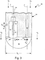
- FIG. 3 is a cross-sectional front view of probe tip 54 along line 3-3 in FIG. 2 .
- two channels extend through probe tip 54 along substantially parallel axes.
- pressure channel 62 and temperature channel 64 are beside each other, with the center of pressure channel 62 being approximately aligned with the center of temperature channel 64 relative to the CL axis of engine 10, and with pressure channel 62 and temperature channel 64 being approximately perpendicular to Ap flow. More specifically, pressure channel 62 extends along pressure axis P through probe tip 54, and temperature channel 64 extends along temperature axis T through probe tip 54.
- Pressure channel 62 begins at pressure orifice 63 in sensor face 56 and extends all of the way to probe head 52 (shown in FIG. 2 ). Pressure channel 62 is in fluid communication with pressure sensor 58 (shown in FIG. 2 ). Thereby, primary air AP can enter pressure channel 62 and the static pressure thereof can be measured by pressure sensor 58.
- Temperature channel 64 begins at temperature orifice 65 in sensor face 56 but only extends a portion of the way to probe head 52. Instead, temperature channel 64 terminates at temperature sensor 60, and temperature sensor 60 electronically communicates with probe head 52 via wires 66. Temperature sensor 60 further includes shaft 68 which extends into temperature channel 64 minimally contacting probe tip 54, which thermally isolates shaft 68 from probe tip 54. Probe tip 54 further includes exit port 70 which extends through probe tip 54, distal from the sensor face 56. Thereby, primary air AP can enter temperature channel 64, pass by shaft 68 which measures the temperature of primary air AP, and exit probe tip 54 via exit port 70, with flow being induced by the differential pressure between temperature channel 64 and exit port 70.
- exit port 70 is located in splitter 38 (between the flowpaths for primary air AP on inner side 35 and secondary air AS on outer side 37, shown in FIG. 2 ) and is oriented laterally (perpendicular to centerline axis CL, shown in FIG. 1 ).
- exit port 70 can have alternate orientations and locations.
- exit port 70 can be located in the flowpath of secondary air AS.
- exit port 70 can be oriented on the upsteam side or the downstream side of probe tip 54 and can extend through strut 24 (shown in FIG. 2 ) such than secondary air AS can inhibit or encourage flow into temperature channel 64, respectively.
- the flow of primary air AP can be affected by pressure orifice 63 and/or temperature orifice 65.
- the center of pressure orifice 63 is at the same axial location as the center of temperature orifice 65.
- probe tip diameter D1 is 25 mm (1.0 in.)
- pressure orifice diameter D2 is 2.5 mm (0.10 in.)
- temperature orifice diameter D3 is 6.4 mm (0.25 in.)
- exit port diameter D4 is 2.5 mm (0.10 in.).
- pressure orifice 63 is spaced laterally apart from temperature orifice 65. Spacing S between the proximate sides of pressure orifice 63 and temperature orifice 65 is between 0.50 and 2.0 times temperature orifice diameter D3. In the illustrated embodiment, spacing S is 4.98 mm (0.196 in.).
- probe assembly 48 allow for the static pressure and total temperature of primary air AP to be measured by a single, compact device. In addition, the measurements can be taken accurately without the flow at pressure channel 62 being disturbed by the flow of primary air AP into temperature channel 64.
Landscapes
- Engineering & Computer Science (AREA)
- Mechanical Engineering (AREA)
- General Engineering & Computer Science (AREA)
- Physics & Mathematics (AREA)
- General Physics & Mathematics (AREA)
- Chemical & Material Sciences (AREA)
- Combustion & Propulsion (AREA)
- Aviation & Aerospace Engineering (AREA)
- Analytical Chemistry (AREA)
- Measuring Fluid Pressure (AREA)
- Measuring Temperature Or Quantity Of Heat (AREA)
Claims (9)
- Gasturbinentriebwerk (10), das sich entlang einer Achse (CL) erstreckt, umfassend:einen Gebläseabschnitt, der eine Vielzahl von Rotorkaskaden (13A-13C) und eine Vielzahl von Statorkaskaden (14A-14D) umfasst;einen Strömungsteiler (38) stromabwärts des Gebläseabschnitts,wobei der Strömungsteiler (38) eine Innenseite (35), eine Außenseite (37) und eine Innenfläche beinhaltet;einen Verdichterabschnitt stromabwärts des Strömungsteilers (38);einen Brennkammerabschnitt stromabwärts des Verdichterabschnitts;einem ersten Turbinenabschnitt stromabwärts des Brennkammerabschnitts, wobei der erste Turbinenabschnitt mit dem Verdichterabschnitt verbunden ist;einen zweiten Turbinenabschnitt stromabwärts des ersten Turbinenabschnitts, wobei der zweite Turbinenabschnitt mit dem Gebläseabschnitt verbunden ist; undeine Sondenbaugruppe (48), umfassend:eine Sondenspitze (54) einschließlich einer Sensorfläche (56);einen Druckkanal (62), der sich in die Sondenspitze (54) durch die Sensorfläche (56) erstreckt; undeinen Temperaturkanal (64), der sich in die Sondenspitze (54) durch die Sensorfläche (56) erstreckt;einen Drucksensor (58) in Fluidverbindung mit dem Druckkanal (62); undeinen Temperatursensor (60) in Fluidverbindung mit dem Temperaturkanal (64);wobei:der Temperaturkanal (64) im Wesentlichen parallel zu dem Druckkanal (62) verläuft; unddie Sensorfläche (56) im Wesentlichen bündig mit der Innenseite (35) des Strömungsteilers (38) ist.
- Gasturbinentriebwerk (10) nach Anspruch 1, wobei der Temperaturkanal (64) eine Austrittsöffnung (70) beinhaltet, die innerhalb des Strömungsteilers (38) positioniert ist.
- Gasturbinentriebwerk (10) nach Anspruch 1 oder 2, wobei der Temperaturkanal (64) eine Austrittsöffnung (70) beinhaltet, die außerhalb des Strömungsteilers (38) positioniert ist.
- Gasturbinentriebwerk (10) nach einem der Ansprüche 1 bis 3, wobei es sich bei dem Temperatursensor (60) um einen Gesamttemperatursensor handelt.
- Gasturbinentriebwerk (10) nach Anspruch 1, ferner umfassend:
eine Austrittsöffnung (70) in Fluidverbindung mit dem Temperaturkanal (64), wobei sich die Austrittsöffnung (70) durch die Sondenspitze (54) distal von der Sensorfläche (56) erstreckt. - Gasturbinentriebwerk (10) nach einem der vorhergehenden Ansprüche, wobei:
die Sondenbaugruppe (48) ferner einen Sondenkopf (52) umfasst und sich ein Kanal zwischen dem Temperatursensor (60) und dem Sondenkopf (52) erstreckt, der fluidisch von dem Druckkanal (62) getrennt ist. - Gasturbinentriebwerk (10) nach einem der vorhergehenden Ansprüche, wobei es sich bei dem Drucksensor (58) um einen Sensor für statischen Druck handelt.
- Gasturbinentriebwerk (10) nach einem der vorhergehenden Ansprüche, wobei die Sensorfläche (56) um nicht mehr als 0,76 mm von der Innenfläche des Strömungsteilers (38) versetzt ist.
- Gasturbinentriebwerk (10) nach einem der vorhergehenden Ansprüche, wobei sich ein Mittelpunkt des Temperaturkanals (64) an der Sensorfläche (56) an im Wesentlichen der gleichen axialen Position befindet wie ein Mittelpunkt des Druckkanals (62) an der Sensorfläche (56).
Applications Claiming Priority (1)
| Application Number | Priority Date | Filing Date | Title |
|---|---|---|---|
| US15/934,615 US10371000B1 (en) | 2018-03-23 | 2018-03-23 | Flush-mount combined static pressure and temperature probe |
Publications (3)
| Publication Number | Publication Date |
|---|---|
| EP3543473A2 EP3543473A2 (de) | 2019-09-25 |
| EP3543473A3 EP3543473A3 (de) | 2019-10-16 |
| EP3543473B1 true EP3543473B1 (de) | 2020-12-23 |
Family
ID=65904028
Family Applications (1)
| Application Number | Title | Priority Date | Filing Date |
|---|---|---|---|
| EP19163896.4A Active EP3543473B1 (de) | 2018-03-23 | 2019-03-19 | Gasturbinentriebwerk mit strömungsteiler mit bündig angeordneter kombinierter sonde für statischen druck und temperatur |
Country Status (2)
| Country | Link |
|---|---|
| US (1) | US10371000B1 (de) |
| EP (1) | EP3543473B1 (de) |
Families Citing this family (8)
| Publication number | Priority date | Publication date | Assignee | Title |
|---|---|---|---|---|
| US10073008B2 (en) * | 2016-01-27 | 2018-09-11 | General Electric Company | Electrostatic sensor |
| US11773745B2 (en) | 2020-02-28 | 2023-10-03 | Rosemount Aerospace Inc. | Pressure and temperature sensors and methods of controlling ice accretion on pressure and temperature sensors |
| US11879345B2 (en) * | 2020-02-28 | 2024-01-23 | Rosemount Aerospace Inc. | Pressure and temperature sensors and methods of removing ice from pressure and temperature sensors |
| US11655726B2 (en) * | 2020-02-28 | 2023-05-23 | Rosemount Aerospace Inc. | Pressure and temperature sensors and related methods |
| CN111220348A (zh) * | 2020-03-06 | 2020-06-02 | 上海海事大学 | 一种复合型五孔压力-温度探针 |
| US11473508B2 (en) * | 2020-03-13 | 2022-10-18 | Rosemount Aerospace Inc. | Flush-mount combined static pressure and temperature probe with flow enhancement feature |
| US11692884B2 (en) | 2020-08-17 | 2023-07-04 | Rosemount Inc. | Thermowell with pressure sensing capabilities |
| CN114110662B (zh) * | 2021-11-25 | 2023-02-10 | 同济大学 | 一种燃气轮机低氮燃烧室 |
Family Cites Families (15)
| Publication number | Priority date | Publication date | Assignee | Title |
|---|---|---|---|---|
| US3605495A (en) | 1969-09-29 | 1971-09-20 | Nasa | Sensing probe |
| GB2124706B (en) | 1982-08-04 | 1986-05-14 | Gen Electric | Gas turbine engine airflow temperature sensor |
| DE10232315B4 (de) * | 2001-11-12 | 2009-05-28 | Temperaturmeßtechnik Geraberg GmbH | Kombinierter Temperatur- und Druckfühler und Verfahren zur Ermittlung von physikalischen Kenngrößen |
| JP3870918B2 (ja) | 2002-10-23 | 2007-01-24 | 株式会社デンソー | 温度センサ一体型圧力センサ装置 |
| US7111982B1 (en) * | 2004-01-30 | 2006-09-26 | Swonger Jr Karl William | Combined temperature and pressure probe for a gas turbine engine |
| US8616064B2 (en) | 2006-04-21 | 2013-12-31 | Kulite Semiconductor Products, Inc. | Combination static and dynamic pressure transducer employing a micro-filter |
| US20110020152A1 (en) * | 2008-04-08 | 2011-01-27 | Volvo Lastvagnar Ab | Compressor |
| US8311684B2 (en) | 2008-12-17 | 2012-11-13 | Pratt & Whitney Canada Corp. | Output flow control in load compressor |
| US20100232930A1 (en) * | 2009-03-16 | 2010-09-16 | Terry Lynn Gregory | Gas turbine engine |
| US8364340B2 (en) | 2009-03-31 | 2013-01-29 | General Electric Company | Method and systems for virtual sensor selection and blending |
| GB201010862D0 (en) * | 2010-06-29 | 2010-08-11 | Rolls Royce Plc | High temperature measurement probe |
| US8725384B2 (en) | 2012-02-10 | 2014-05-13 | General Electic Company | Detection system and method to detect flame holding event |
| DE102012213161B4 (de) * | 2012-07-26 | 2019-07-25 | BMTS Technology GmbH & Co. KG | Turbine für eine Brennkraftmaschine |
| CA2950274A1 (en) * | 2014-05-29 | 2016-03-03 | General Electric Company | Turbine engine, components, and methods of cooling same |
| US10073008B2 (en) | 2016-01-27 | 2018-09-11 | General Electric Company | Electrostatic sensor |
-
2018
- 2018-03-23 US US15/934,615 patent/US10371000B1/en active Active
-
2019
- 2019-03-19 EP EP19163896.4A patent/EP3543473B1/de active Active
Non-Patent Citations (1)
| Title |
|---|
| None * |
Also Published As
| Publication number | Publication date |
|---|---|
| EP3543473A3 (de) | 2019-10-16 |
| US10371000B1 (en) | 2019-08-06 |
| EP3543473A2 (de) | 2019-09-25 |
Similar Documents
| Publication | Publication Date | Title |
|---|---|---|
| EP3543473B1 (de) | Gasturbinentriebwerk mit strömungsteiler mit bündig angeordneter kombinierter sonde für statischen druck und temperatur | |
| US10578498B2 (en) | Air temperature sensor | |
| US20180372556A1 (en) | Air temperature sensor | |
| EP3014089B1 (de) | Übermässige verformungsüberwachung anhand eines lüfterantriebssystems | |
| EP3580433A1 (de) | Drucksensoranordnung für einen turbinenmotor | |
| JP6505179B2 (ja) | 排気ガス温度検出プローブアセンブリ | |
| JPS6349164B2 (de) | ||
| EP3301418B1 (de) | Abgastemperaturmesssondenanordnung | |
| US9116051B2 (en) | Actively cooled gas turbine sensor probe housing | |
| EP3879250A1 (de) | Flächenbündige kombinierte sonde für statischen druck und temperatur mit durchflussverbesserungsfunktion | |
| EP3418703B1 (de) | Lufttemperatursensor | |
| US4050306A (en) | Method and apparatus for measuring pressures | |
| EP3301419B1 (de) | Abgastemperaturmesssondenanordnung | |
| US11175187B2 (en) | Air temperature sensor having a bushing | |
| US10329921B2 (en) | Cooling configuration for a component | |
| US10545057B2 (en) | Air temperature sensor and method of reducing error | |
| US11624662B2 (en) | Exhaust gas temperature sensor | |
| EP4372211A1 (de) | Sonde für eine gasturbine | |
| US10731477B2 (en) | Woven skin cores for turbine airfoils |
Legal Events
| Date | Code | Title | Description |
|---|---|---|---|
| PUAI | Public reference made under article 153(3) epc to a published international application that has entered the european phase |
Free format text: ORIGINAL CODE: 0009012 |
|
| STAA | Information on the status of an ep patent application or granted ep patent |
Free format text: STATUS: THE APPLICATION HAS BEEN PUBLISHED |
|
| PUAL | Search report despatched |
Free format text: ORIGINAL CODE: 0009013 |
|
| AK | Designated contracting states |
Kind code of ref document: A2 Designated state(s): AL AT BE BG CH CY CZ DE DK EE ES FI FR GB GR HR HU IE IS IT LI LT LU LV MC MK MT NL NO PL PT RO RS SE SI SK SM TR |
|
| AX | Request for extension of the european patent |
Extension state: BA ME |
|
| AK | Designated contracting states |
Kind code of ref document: A3 Designated state(s): AL AT BE BG CH CY CZ DE DK EE ES FI FR GB GR HR HU IE IS IT LI LT LU LV MC MK MT NL NO PL PT RO RS SE SI SK SM TR |
|
| AX | Request for extension of the european patent |
Extension state: BA ME |
|
| RIC1 | Information provided on ipc code assigned before grant |
Ipc: F01D 17/08 20060101AFI20190910BHEP Ipc: G01L 19/00 20060101ALI20190910BHEP Ipc: G01K 13/02 20060101ALI20190910BHEP |
|
| STAA | Information on the status of an ep patent application or granted ep patent |
Free format text: STATUS: REQUEST FOR EXAMINATION WAS MADE |
|
| 17P | Request for examination filed |
Effective date: 20191203 |
|
| RBV | Designated contracting states (corrected) |
Designated state(s): AL AT BE BG CH CY CZ DE DK EE ES FI FR GB GR HR HU IE IS IT LI LT LU LV MC MK MT NL NO PL PT RO RS SE SI SK SM TR |
|
| GRAP | Despatch of communication of intention to grant a patent |
Free format text: ORIGINAL CODE: EPIDOSNIGR1 |
|
| STAA | Information on the status of an ep patent application or granted ep patent |
Free format text: STATUS: GRANT OF PATENT IS INTENDED |
|
| INTG | Intention to grant announced |
Effective date: 20200723 |
|
| GRAS | Grant fee paid |
Free format text: ORIGINAL CODE: EPIDOSNIGR3 |
|
| GRAA | (expected) grant |
Free format text: ORIGINAL CODE: 0009210 |
|
| STAA | Information on the status of an ep patent application or granted ep patent |
Free format text: STATUS: THE PATENT HAS BEEN GRANTED |
|
| AK | Designated contracting states |
Kind code of ref document: B1 Designated state(s): AL AT BE BG CH CY CZ DE DK EE ES FI FR GB GR HR HU IE IS IT LI LT LU LV MC MK MT NL NO PL PT RO RS SE SI SK SM TR |
|
| REG | Reference to a national code |
Ref country code: GB Ref legal event code: FG4D |
|
| REG | Reference to a national code |
Ref country code: DE Ref legal event code: R096 Ref document number: 602019001822 Country of ref document: DE |
|
| REG | Reference to a national code |
Ref country code: AT Ref legal event code: REF Ref document number: 1347916 Country of ref document: AT Kind code of ref document: T Effective date: 20210115 |
|
| REG | Reference to a national code |
Ref country code: IE Ref legal event code: FG4D |
|
| PG25 | Lapsed in a contracting state [announced via postgrant information from national office to epo] |
Ref country code: NO Free format text: LAPSE BECAUSE OF FAILURE TO SUBMIT A TRANSLATION OF THE DESCRIPTION OR TO PAY THE FEE WITHIN THE PRESCRIBED TIME-LIMIT Effective date: 20210323 Ref country code: GR Free format text: LAPSE BECAUSE OF FAILURE TO SUBMIT A TRANSLATION OF THE DESCRIPTION OR TO PAY THE FEE WITHIN THE PRESCRIBED TIME-LIMIT Effective date: 20210324 Ref country code: RS Free format text: LAPSE BECAUSE OF FAILURE TO SUBMIT A TRANSLATION OF THE DESCRIPTION OR TO PAY THE FEE WITHIN THE PRESCRIBED TIME-LIMIT Effective date: 20201223 Ref country code: FI Free format text: LAPSE BECAUSE OF FAILURE TO SUBMIT A TRANSLATION OF THE DESCRIPTION OR TO PAY THE FEE WITHIN THE PRESCRIBED TIME-LIMIT Effective date: 20201223 |
|
| REG | Reference to a national code |
Ref country code: AT Ref legal event code: MK05 Ref document number: 1347916 Country of ref document: AT Kind code of ref document: T Effective date: 20201223 |
|
| REG | Reference to a national code |
Ref country code: NL Ref legal event code: MP Effective date: 20201223 |
|
| PG25 | Lapsed in a contracting state [announced via postgrant information from national office to epo] |
Ref country code: BG Free format text: LAPSE BECAUSE OF FAILURE TO SUBMIT A TRANSLATION OF THE DESCRIPTION OR TO PAY THE FEE WITHIN THE PRESCRIBED TIME-LIMIT Effective date: 20210323 Ref country code: SE Free format text: LAPSE BECAUSE OF FAILURE TO SUBMIT A TRANSLATION OF THE DESCRIPTION OR TO PAY THE FEE WITHIN THE PRESCRIBED TIME-LIMIT Effective date: 20201223 Ref country code: LV Free format text: LAPSE BECAUSE OF FAILURE TO SUBMIT A TRANSLATION OF THE DESCRIPTION OR TO PAY THE FEE WITHIN THE PRESCRIBED TIME-LIMIT Effective date: 20201223 |
|
| PG25 | Lapsed in a contracting state [announced via postgrant information from national office to epo] |
Ref country code: NL Free format text: LAPSE BECAUSE OF FAILURE TO SUBMIT A TRANSLATION OF THE DESCRIPTION OR TO PAY THE FEE WITHIN THE PRESCRIBED TIME-LIMIT Effective date: 20201223 Ref country code: HR Free format text: LAPSE BECAUSE OF FAILURE TO SUBMIT A TRANSLATION OF THE DESCRIPTION OR TO PAY THE FEE WITHIN THE PRESCRIBED TIME-LIMIT Effective date: 20201223 |
|
| REG | Reference to a national code |
Ref country code: LT Ref legal event code: MG9D |
|
| PG25 | Lapsed in a contracting state [announced via postgrant information from national office to epo] |
Ref country code: LT Free format text: LAPSE BECAUSE OF FAILURE TO SUBMIT A TRANSLATION OF THE DESCRIPTION OR TO PAY THE FEE WITHIN THE PRESCRIBED TIME-LIMIT Effective date: 20201223 Ref country code: PT Free format text: LAPSE BECAUSE OF FAILURE TO SUBMIT A TRANSLATION OF THE DESCRIPTION OR TO PAY THE FEE WITHIN THE PRESCRIBED TIME-LIMIT Effective date: 20210423 Ref country code: RO Free format text: LAPSE BECAUSE OF FAILURE TO SUBMIT A TRANSLATION OF THE DESCRIPTION OR TO PAY THE FEE WITHIN THE PRESCRIBED TIME-LIMIT Effective date: 20201223 Ref country code: SK Free format text: LAPSE BECAUSE OF FAILURE TO SUBMIT A TRANSLATION OF THE DESCRIPTION OR TO PAY THE FEE WITHIN THE PRESCRIBED TIME-LIMIT Effective date: 20201223 Ref country code: SM Free format text: LAPSE BECAUSE OF FAILURE TO SUBMIT A TRANSLATION OF THE DESCRIPTION OR TO PAY THE FEE WITHIN THE PRESCRIBED TIME-LIMIT Effective date: 20201223 Ref country code: EE Free format text: LAPSE BECAUSE OF FAILURE TO SUBMIT A TRANSLATION OF THE DESCRIPTION OR TO PAY THE FEE WITHIN THE PRESCRIBED TIME-LIMIT Effective date: 20201223 Ref country code: CZ Free format text: LAPSE BECAUSE OF FAILURE TO SUBMIT A TRANSLATION OF THE DESCRIPTION OR TO PAY THE FEE WITHIN THE PRESCRIBED TIME-LIMIT Effective date: 20201223 |
|
| PG25 | Lapsed in a contracting state [announced via postgrant information from national office to epo] |
Ref country code: PL Free format text: LAPSE BECAUSE OF FAILURE TO SUBMIT A TRANSLATION OF THE DESCRIPTION OR TO PAY THE FEE WITHIN THE PRESCRIBED TIME-LIMIT Effective date: 20201223 Ref country code: AT Free format text: LAPSE BECAUSE OF FAILURE TO SUBMIT A TRANSLATION OF THE DESCRIPTION OR TO PAY THE FEE WITHIN THE PRESCRIBED TIME-LIMIT Effective date: 20201223 |
|
| REG | Reference to a national code |
Ref country code: DE Ref legal event code: R097 Ref document number: 602019001822 Country of ref document: DE |
|
| PG25 | Lapsed in a contracting state [announced via postgrant information from national office to epo] |
Ref country code: IS Free format text: LAPSE BECAUSE OF FAILURE TO SUBMIT A TRANSLATION OF THE DESCRIPTION OR TO PAY THE FEE WITHIN THE PRESCRIBED TIME-LIMIT Effective date: 20210423 |
|
| PG25 | Lapsed in a contracting state [announced via postgrant information from national office to epo] |
Ref country code: AL Free format text: LAPSE BECAUSE OF FAILURE TO SUBMIT A TRANSLATION OF THE DESCRIPTION OR TO PAY THE FEE WITHIN THE PRESCRIBED TIME-LIMIT Effective date: 20201223 Ref country code: MC Free format text: LAPSE BECAUSE OF FAILURE TO SUBMIT A TRANSLATION OF THE DESCRIPTION OR TO PAY THE FEE WITHIN THE PRESCRIBED TIME-LIMIT Effective date: 20201223 Ref country code: IT Free format text: LAPSE BECAUSE OF FAILURE TO SUBMIT A TRANSLATION OF THE DESCRIPTION OR TO PAY THE FEE WITHIN THE PRESCRIBED TIME-LIMIT Effective date: 20201223 |
|
| PLBE | No opposition filed within time limit |
Free format text: ORIGINAL CODE: 0009261 |
|
| STAA | Information on the status of an ep patent application or granted ep patent |
Free format text: STATUS: NO OPPOSITION FILED WITHIN TIME LIMIT |
|
| PG25 | Lapsed in a contracting state [announced via postgrant information from national office to epo] |
Ref country code: DK Free format text: LAPSE BECAUSE OF FAILURE TO SUBMIT A TRANSLATION OF THE DESCRIPTION OR TO PAY THE FEE WITHIN THE PRESCRIBED TIME-LIMIT Effective date: 20201223 |
|
| 26N | No opposition filed |
Effective date: 20210924 |
|
| REG | Reference to a national code |
Ref country code: BE Ref legal event code: MM Effective date: 20210331 |
|
| PG25 | Lapsed in a contracting state [announced via postgrant information from national office to epo] |
Ref country code: IE Free format text: LAPSE BECAUSE OF NON-PAYMENT OF DUE FEES Effective date: 20210319 Ref country code: LU Free format text: LAPSE BECAUSE OF NON-PAYMENT OF DUE FEES Effective date: 20210319 Ref country code: ES Free format text: LAPSE BECAUSE OF FAILURE TO SUBMIT A TRANSLATION OF THE DESCRIPTION OR TO PAY THE FEE WITHIN THE PRESCRIBED TIME-LIMIT Effective date: 20201223 |
|
| PG25 | Lapsed in a contracting state [announced via postgrant information from national office to epo] |
Ref country code: SI Free format text: LAPSE BECAUSE OF FAILURE TO SUBMIT A TRANSLATION OF THE DESCRIPTION OR TO PAY THE FEE WITHIN THE PRESCRIBED TIME-LIMIT Effective date: 20201223 |
|
| PG25 | Lapsed in a contracting state [announced via postgrant information from national office to epo] |
Ref country code: IS Free format text: LAPSE BECAUSE OF FAILURE TO SUBMIT A TRANSLATION OF THE DESCRIPTION OR TO PAY THE FEE WITHIN THE PRESCRIBED TIME-LIMIT Effective date: 20210423 |
|
| PG25 | Lapsed in a contracting state [announced via postgrant information from national office to epo] |
Ref country code: BE Free format text: LAPSE BECAUSE OF NON-PAYMENT OF DUE FEES Effective date: 20210331 |
|
| REG | Reference to a national code |
Ref country code: CH Ref legal event code: PL |
|
| PG25 | Lapsed in a contracting state [announced via postgrant information from national office to epo] |
Ref country code: LI Free format text: LAPSE BECAUSE OF NON-PAYMENT OF DUE FEES Effective date: 20220331 Ref country code: CH Free format text: LAPSE BECAUSE OF NON-PAYMENT OF DUE FEES Effective date: 20220331 |
|
| PGFP | Annual fee paid to national office [announced via postgrant information from national office to epo] |
Ref country code: FR Payment date: 20230222 Year of fee payment: 5 |
|
| PG25 | Lapsed in a contracting state [announced via postgrant information from national office to epo] |
Ref country code: CY Free format text: LAPSE BECAUSE OF FAILURE TO SUBMIT A TRANSLATION OF THE DESCRIPTION OR TO PAY THE FEE WITHIN THE PRESCRIBED TIME-LIMIT Effective date: 20201223 |
|
| PG25 | Lapsed in a contracting state [announced via postgrant information from national office to epo] |
Ref country code: HU Free format text: LAPSE BECAUSE OF FAILURE TO SUBMIT A TRANSLATION OF THE DESCRIPTION OR TO PAY THE FEE WITHIN THE PRESCRIBED TIME-LIMIT; INVALID AB INITIO Effective date: 20190319 |
|
| PG25 | Lapsed in a contracting state [announced via postgrant information from national office to epo] |
Ref country code: MK Free format text: LAPSE BECAUSE OF FAILURE TO SUBMIT A TRANSLATION OF THE DESCRIPTION OR TO PAY THE FEE WITHIN THE PRESCRIBED TIME-LIMIT Effective date: 20201223 |
|
| PGFP | Annual fee paid to national office [announced via postgrant information from national office to epo] |
Ref country code: DE Payment date: 20240220 Year of fee payment: 6 Ref country code: GB Payment date: 20240221 Year of fee payment: 6 |