EP3543406B1 - A pile for a pile wall and a method of manufacturing such a pile - Google Patents
A pile for a pile wall and a method of manufacturing such a pile Download PDFInfo
- Publication number
- EP3543406B1 EP3543406B1 EP18163727.3A EP18163727A EP3543406B1 EP 3543406 B1 EP3543406 B1 EP 3543406B1 EP 18163727 A EP18163727 A EP 18163727A EP 3543406 B1 EP3543406 B1 EP 3543406B1
- Authority
- EP
- European Patent Office
- Prior art keywords
- pile
- male connection
- connection portion
- male
- perimeter profile
- Prior art date
- Legal status (The legal status is an assumption and is not a legal conclusion. Google has not performed a legal analysis and makes no representation as to the accuracy of the status listed.)
- Active
Links
Images




Classifications
-
- E—FIXED CONSTRUCTIONS
- E02—HYDRAULIC ENGINEERING; FOUNDATIONS; SOIL SHIFTING
- E02D—FOUNDATIONS; EXCAVATIONS; EMBANKMENTS; UNDERGROUND OR UNDERWATER STRUCTURES
- E02D5/00—Bulkheads, piles, or other structural elements specially adapted to foundation engineering
- E02D5/02—Sheet piles or sheet pile bulkheads
- E02D5/03—Prefabricated parts, e.g. composite sheet piles
- E02D5/04—Prefabricated parts, e.g. composite sheet piles made of steel
- E02D5/08—Locking forms; Edge joints; Pile crossings; Branch pieces
-
- E—FIXED CONSTRUCTIONS
- E02—HYDRAULIC ENGINEERING; FOUNDATIONS; SOIL SHIFTING
- E02D—FOUNDATIONS; EXCAVATIONS; EMBANKMENTS; UNDERGROUND OR UNDERWATER STRUCTURES
- E02D5/00—Bulkheads, piles, or other structural elements specially adapted to foundation engineering
- E02D5/22—Piles
- E02D5/24—Prefabricated piles
- E02D5/28—Prefabricated piles made of steel or other metals
- E02D5/285—Prefabricated piles made of steel or other metals tubular, e.g. prefabricated from sheet pile elements
-
- E—FIXED CONSTRUCTIONS
- E02—HYDRAULIC ENGINEERING; FOUNDATIONS; SOIL SHIFTING
- E02D—FOUNDATIONS; EXCAVATIONS; EMBANKMENTS; UNDERGROUND OR UNDERWATER STRUCTURES
- E02D5/00—Bulkheads, piles, or other structural elements specially adapted to foundation engineering
- E02D5/02—Sheet piles or sheet pile bulkheads
- E02D5/03—Prefabricated parts, e.g. composite sheet piles
- E02D5/04—Prefabricated parts, e.g. composite sheet piles made of steel
-
- E—FIXED CONSTRUCTIONS
- E02—HYDRAULIC ENGINEERING; FOUNDATIONS; SOIL SHIFTING
- E02D—FOUNDATIONS; EXCAVATIONS; EMBANKMENTS; UNDERGROUND OR UNDERWATER STRUCTURES
- E02D5/00—Bulkheads, piles, or other structural elements specially adapted to foundation engineering
- E02D5/72—Pile shoes
Definitions
- the present disclosure relates to a pile for a pile wall according to the preamble of claim 1. Moreover, the present disclosure relates to a connection arrangement for connecting piles of a pile wall and also to a method for manufacturing a pile for a pile wall.
- Pile walls are well known for being used as retaining walls and foundation structures.
- the piles of a pile wall may for example be of tubular shape and be connected by interconnecting members, such as male/female connections, hook connections etc.
- the walls may be used for bearing both vertical and horizontal loads and typically tubular pile walls may be able to bear larger loads than for example conventional sheet pile walls.
- the connecting members for connecting tubular shaped piles are commonly welded onto the tubular shaped pile.
- WO 2017/060567 A1 discloses a pile wall made of tubular piles, wherein the piles have been connected by male/female connections. Especially, the female connection has been arranged inside the pile in order to reduce the diameter of the pile.
- the proposed design seems to be complicated and also difficult to realize in a cost-efficient manner.
- Another pile is disclosed in document JP2002309571A .
- an object of the present invention is to provide an improved pile for a pile wall, a connection arrangement comprising such a pile and a method for manufacturing a pile for a pile wall.
- the object is provided by a pile for a pile wall, wherein the pile extends longitudinally between a first and a second end and comprises at least one perimeter profile in a cross section which is essentially perpendicular to the longitudinal extension of the pile.
- the perimeter profile encloses an uninterrupted area in said cross section, wherein at least one section of the perimeter profile extends outwardly, i.e. protrudes, and forms a first male connection portion, and the uninterrupted area extends into the first male connection portion, thereby forming a load bearing portion of the pile.
- an improved pile for a pile wall is provided. More specifically, by designing the pile such that at least one male connection portion is integrated into the perimeter profile of the pile as disclosed herein, an improved and more robust connection may be realized. Hence, according to the present invention, the at least one male connection portion is integrated into the perimeter profile, thereby forming a load bearing portion of the pile. Furthermore, the inventor has realized that a more cost-efficient pile wall may be accomplished. For example, the manufacturing process of the pile may be facilitated. Still further, due to the proposed design, less welding operations may be needed since parts of the connection arrangement of the pile wall are integrated into the pile, resulting in a simplified connection arrangement. Prior art solutions have for example proposed to use more welding connections and/or to make complicated pile/connection designs. By the present invention, drawbacks of the prior art have now been reduced or even eliminated.
- uninterrupted area means a continuous area which is defined and limited by the perimeter profile of the pile and which is not interrupted by the pile or the pile's perimeter profile in a cross section thereof.
- the uninterrupted area is an area which is enclosed by an inner pile wall surface following the perimeter profile.
- an uninterrupted area may be regarded as one continuous area inside the pile without any interruptions/dividers which forms part of the perimeter profile.
- the uninterrupted area may still be filled with or include one or more members/elements which are not part of the pile or the pile's perimeter profile, such as concrete, soil, or other members/elements as for example disclosed herein.
- a load bearing portion of the pile as used herein may be defined as a portion of the pile which is intended to bear building loads to earth during use of the pile.
- the perimeter profile may present at least one second section extending outwardly forming a second male connection portion, wherein the uninterrupted area extends into the second male connection portion, i.e. into both the first and second male connection portions or all of the male connection portions.
- the first and second male connection portions may be located on substantially opposite sides of the perimeter profile.
- the first and second male connection portions may be located about 180 degrees from each other in the perimeter profile.
- the first and second male connection portions may also be located with other angles relative each other, which may result in an angled pile wall design.
- the pile may comprise more than two such male connection portions.
- the pile is hollow.
- the pile comprises an open space which is enclosed by the perimeter profile of the pile.
- the space may be empty, but it may also be filled with other materials which are not part of the pile's perimeter profile.
- At least one of the first and second male connection portions may be configured such that it presents at least one tapering profile which tapers inwardly towards a center of the cross section of the perimeter profile.
- the center may be defined as the mass center of the cross section of the perimeter profile. In the case the perimeter profile is circular, the center may be defined as the center point of the circle.
- At least one of the first and second male connection portions may comprise an intermediate waist portion and an outer top portion being located outwardly in respect of the intermediate waist portion.
- the pile may comprise a pile body and a male connection portion which comprises a top portion and an intermediate waist portion which is located between the top portion and the pile body.
- a length of the waist portion as seen in a direction being essentially transverse to the outward direction of the at least one male connection portion, is smaller than a corresponding transverse length of the top portion.
- the first male connection portion extends along at least 50 %, such as along at least 60%, at least 70% or at least 80% of the longitudinal extension of the pile, and preferably along the complete longitudinal extension of the pile.
- an improved connection and also facilitated manufacturing of the pile may be accomplished when at least one of the first and second male connection portions extends along the complete extension of the pile.
- the pile is made of metal, preferably steel or iron.
- the design of the pile as disclosed herein has been found to be especially advantageous when the pile is made of metal, and especially when it is made of steel.
- a steel pile is also known for being able to bear large loads, both in a longitudinal/vertical and in a transverse/horizontal direction of the pile and the pile wall.
- the cross section of the pile may be of tubular shape, such as an oval or circular shape.
- the perimeter profile of the pile may form a tubular shape, such as an oval and circular shape, when excluding the shape of the at least one male connection portion.
- the at least one male connection portion may deviate from the tubular shape.
- Such a shape may be advantageous in that it may be able to accommodate larger loads compared to other shapes, and also avoid or reduce the risk of high stress areas in the pile.
- a smooth perimeter profile without any unnecessary sharp corners/edges etc. may be provided and be advantageous over other possible cross sectional profile shapes, such as any regular or non-regular polygonal cross sectional profile shape having rounded corners.
- tubular shapes and the like, such as other smooth perimeter profile shapes may be advantageous for manufacturing reasons.
- the perimeter profile of the pile may be of substantially uniform thickness along its perimeter.
- the thickness of the perimeter profile may vary. Just as a matter of example, the thickness may vary such that its thickest portion is up to 30 % thicker than the narrowest portion of the perimeter profile.
- the portion of the uninterrupted area which extends into the at least one male connection portion may correspond to at least 30, 40, 50, 60, 70, 80 or 90 % of the male connection portion's total area as seen in the cross section.
- the pile may be produced by cold forming and/or hot forming.
- the inventor has realized that the pile design as disclosed herein has shown to be especially advantageous when the pile is produced by these manufacturing techniques, and especially when the pile's cross sectional shape is produced by a cold forming operation.
- the pile may further comprise a drilling member which is located at one of the ends of the pile for drilling the pile into ground.
- the pile may be drilled into ground by a centric or eccentric drilling method.
- the pile may be installed by drilling through stones and boulders, and even into bedrock or seabed.
- the drilling member may be configured as a ring member comprising a number of hard and tough drilling elements.
- a diameter of the ring member may be essentially equal to or larger than a largest diameter of the pile.
- the pile may also be driven into ground by a ramming and/or vibrating operation.
- the pile may further comprise a casing shoe located inside and/or at the end part of the pile at one of the ends of said pile.
- a casing shoe may be provided for increasing a robustness and strength of the pile at the end which is intended to be firstly put into ground.
- a casing shoe may advantageously be used when the pile is drilled into ground.
- the casing shoe may be formed such that it extends into at least one of the first and second male connection portions. Thereby the shape of the male connection portions may not be destroyed when the pile is driven or drilled into ground.
- the pile may comprise a longitudinal weld extending from the first to the second end of the pile. It has been found to be especially advantageous to use a longitudinal weld for generating the enclosing perimeter profile of the pile as disclosed herein.
- a longitudinal weld is herein referring to a weld comprising an essentially straight weld seam which extends longitudinally between the ends of the pile. Hence, this does not include a helical weld seam which may also be used for creating an enclosing pile perimeter profile.
- the pile may further comprise a pipe, such as a so called grout pipe, for injecting a second material, preferably concrete, into the ground and/or into an inner volume of the pile being defined and limited by the perimeter profile of the pile.
- the pipe may be located inside the inner volume of the pile or outside of the pile.
- the pipe may be located in the area of the uninterrupted area which extends into at least one of the first and second male connection portions.
- the uninterrupted area may at least partly be filled with a second material, preferably concrete, during use of said pile.
- connection arrangement for connecting piles of a pile wall, which comprises at least one pile according to any one of the embodiments according to the first aspect of the invention.
- connection arrangement comprises a connection member for connecting the at least one pile to a second pile, wherein the connection member comprises at least one female connection portion for connecting the connection member to the at least one male connection portion of the at least one pile.
- connection arrangement for connecting piles of a pile wall of the invention are largely analogous to the advantages as presented in relation to the pile of the invention and vice versa.
- the connection arrangement results in a cost-efficient and robust design where a male connection portion is integrated into the perimeter profile of the pile.
- a male connection portion is integrated into the perimeter profile of the pile.
- connection member may comprise at least one second female connection portion for connecting the connection member to the second pile.
- connection member may be connected and/or additionally connected to the first or second pile by at least one weld.
- connection member may be made of one piece, or alternatively it may be made of more than one piece, such as pieces which have been welded together forming e.g. two female connection portions. Still optionally, the connection member may be configured to extend along at least a part of the longitudinal extension of the piles, or alternatively it may extend along substantially the complete extension of the piles. Still further, there may be more than one connection member along the longitudinal extension of the piles.
- the object is provided by a method for manufacturing a pile according to the invention, wherein the pile is formed by cold forming and/or hot forming. Still optionally, the pile may be manufactured by additional steps, such as longitudinal welding, for example high frequency induction welding, other forming steps, weld trimming, cooling and testing, calibrating and shaping, oiling and cutting, inspection and marking etc.
- manufacturing a pile according to the present invention may lead to a reduction in production time of up to 20 times, or even more, compared to a pile comprising interlocking members which are welded onto the pile, such as a tube shaped pile. This is mainly due the new design removing, or at least reducing, the need for welding, which is a time consuming operation.
- Figure 1 concerns a prior art design of connecting piles of a pile wall.
- the pile wall comprises a first pile 100 and a second pile 100', wherein connection members 110 and 110', in the form of male/female connections, have been welded to the respective piles 100 and 100'. Therefore, the first pile 100 presents two welds 111 and the second pile 100' presents corresponding welds 111'.
- the connection members 110 and 110' are separate parts from the piles 100 and 100', respectively, and are therefore not well suited for transferring loads during use. This is due to that the welds are not strong enough and suited for transferring the loads which the pile is intended to accommodate during use.
- the tubular shaped piles 100 and 100' have first been produced into tube form, in e.g. a cold forming step, whereby the connection members 110 and 110' have been joined to the respective piles 100 and 100' after the cold forming step.
- a pile 1 for a pile wall is depicted according to an example embodiment of the present invention.
- the figure shows a cross sectional view of a pile 1, which cross section is perpendicular to a longitudinal extension of the pile 1.
- the pile 1 extends longitudinally between a first and a second end and comprises at least one perimeter profile 2 in the cross section of the pile 1.
- the perimeter profile 2 is a load bearing part of the pile 1 intended for transferring building loads to earth for example during use and further encloses an uninterrupted area 3.
- at least one section 4 of the perimeter profile 2 extends outwardly and forms a first male connection portion 4, wherein the uninterrupted area 3 extends into the first male connection portion 4.
- the male connection portion 4 has been integrated into the perimeter profile 2 in a way allowing a robust connection and a facilitated manufacturing process, and is a load bearing portion of the pile (1).
- at least one of the sections 4 and 5 may extend along 1/2, 1/3, 1/4, 1/5, 1/6, 1/7, 1/8, 1/9, 1/10 or less of the perimeter profile's perimeter.
- the pile 1 further comprises a second male connection portion 5 configured in a similar manner as the male connection portion 4.
- the first and second male connection portions 4 and 5 are angularly offset by about 180 degrees, i.e. they are located on essentially opposite sides of the perimeter profile 2.
- the first and second male connection portions 4 and 5 are configured and dimensioned in a similar manner.
- the first male connection portion 4 is configured as follows: It comprises an intermediate waist portion 41 and an outer top portion 42 which is located outwardly in respect of the intermediate waist portion 41.
- a length D 1 of the waist portion 41, as seen in a direction being essentially transverse to the outward direction of the first male connection portion 4, is smaller than a corresponding transverse length D 2 of the top portion 42.
- the second male connection portion 5 is configured in a similar manner, i.e. it comprises an intermediate waist portion 51 and an outer top portion 52 which is located outwardly in respect of the intermediate waist portion 51.
- a length of the waist portion 51, as seen in a direction being essentially transverse to the outward direction of the second male connection portion 5, is smaller than a corresponding transverse length of the top portion 52.
- the first and second male connection portions 4 and 5 form respective tapering profiles such that they can interlock with respective and corresponding female connection members.
- the thickness of the pile's perimeter profile 2 including the thickness of the male connection portion(s) need not necessarily be uniform.
- the thickness of the perimeter profile 2 is substantially uniform.
- a pile according to the present invention including the male connection portion(s) is preferably manufactured as a single component rather than comprising several separate elements that are connected together, by welding for example. More particularly, in an example embodiment of the present invention, the pile is made in one piece, whereby the at least one male connection portion is integrated into the pile's perimeter profile.
- connection member 6' comprises one female connection portion 61' for connecting the connection member 6' to one of the first and second male connection portions 4 and 5 of the pile 1 as for example seen in figure 2a .
- the connection member 6' is configured such that a transverse length d 1 of an opening of the female connection portion 61' is smaller than a corresponding length d 2 which is located inside the opening of the female connection portion 61'.
- connection member 6 corresponds to each other such that a rigid male/female connection between the pile 1 and the connection member 6' is accomplished.
- the pile 1 and the corresponding connection member 6' may be connected by moving the two members relative each other in the longitudinal direction thereof. In other words, the pile 1 and the connection member 6' may be connected by sliding the connection member 6' onto the male connection portion 4, or vice versa.
- An alternative to the connection member 6' is the connection member 6".
- This connection member comprises a first and a second female connection portion, 61" and 62", respectively, which are located on essentially opposite sides to each other.
- connection member 6" may interconnect a first and a second pile comprising respective male connection portions.
- this connection member 6" has been made by welding together two connection members which are similar to the connection member 6', forming essentially an I-shaped or H-shaped member.
- a similar connection member to 6" can be seen to the right in the figure, which shows a connection member 6′′′ which is made in one piece and forms essentially an I-shape or H-shape.
- the connection member 6′′′ comprises corresponding female connection portions 61′′′ and 62′′′.
- the female sections may be accomplished by bending its protruding walls inwardly, thereby forming a tapering profile.
- FIG. 2a and 2b together depicts a connection arrangement 10 according to example embodiments of the present invention.
- FIG. 2c shows another example embodiment of a pile 1 according to the present invention.
- the pile 1 is similar in configuration as the pile shown in figure 2a , but with the difference that the pile 1 here presents one male connection portion 4.
- this pile 1 could be located at an end section of a pile wall.
- a connection member 6' as shown in figure 2b may be connected to the pile 1 at the side being opposite, or in any other angle, to the location of the male connection member 4, e.g. by welding.
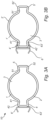
- FIGS 3a and 3b two piles 1 and 1', an intermediate connection member 6" and an additional connection member 6' are depicted according to an example embodiment of the present invention.
- the pile 1 in figure 3a is similarly configured as the pile as seen in figure 2a , with the difference that the connection member 6' has been welded by a weld 63' onto the top portion 42 of the first male connection portion 4. Thereby the pile 1 may be connected to an additional pile (not shown) via the connection member 6'. Moreover, the pile 1 may be connected to the second pile 1' by its male connection portion 5 via another connection member 6".
- the first and the second piles 1 and 1' are in this embodiment similarly shaped, and therefore the reference numbers for the second pile 1' with the same number reference except for the apostrophe correspond to similar elements as the elements with the reference numbers of the first pile 1. Hence, these parts of the second pile 1' are not further detailed herein.
- the additional connection member 6" has been connected to the pile 1' via a male/female connection, 4' and 61", respectively (see also 6" in figure 2b for details). Additionally, the connection member 6" has also been welded onto the pile 1' by at least one weld 63'.
- FIG. 3a and 3b also depicts a connection arrangement 10 according to example embodiments of the present invention.
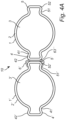
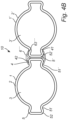
- connection arrangement 10 and a pile wall according to an example embodiment of the present invention.
- a connection member 6' of the first kind is used and comprises one female connection portion.
- a connection member 6′′′ of the third kind is used. It shall be noted that a pile wall with several connections may use any one, including a combination, of the different kinds of connection members as disclosed herein.
- connection member 6′′′ has also been connected to the pile 1' by a weld 63′′′ in addition to the male/female connections. This may further strengthen the connection.
- weld 63′′′ may not need to comprise weld seams which extend along the complete extension of the pile. Rather, and more preferably, shorter welds may be made, such as providing welding dots or points or seams along the pile's extension. Thereby, less time is needed in such welding steps.
- welds may only be used for positioning the components relative each other and the connections between the piles are rather accomplished via the rigid mechanical male/female connection members as disclosed herein.
- FIGS 5a-5d another example embodiment of a pile 1 according to the present invention is depicted.
- the pile 1 further comprises a drilling member 7 for drilling the pile 1 into ground.
- a casing shoe 8 is depicted located at one of the end sections of the pile 1.
- the casing shoe 8 may be used as a strengthening and reinforcing element.
- a pipe 9 configured as a grout pipe 9 is also provided inside the pile 1 and extends between the longitudinal end portions of the pile 1.
- the pipe 9 may for example be located in the inner area of one of the first or second male connection portions.
- Figure 5a is a view of the pile 1 from above.
- Figures 5b and 5c show a cross section A-A as indicated in figure 5a of the end portion of the pile 1 which is intended to be driven/drilled into ground.
- Figure 5d show a cross section B-B as also indicated in figure 5a .
- the casing shoe 8 may be connected to the pile 1 by a weld 81.
- the grout pipe 9 may be used to fill the hole where the pile 1 is located.
- the filler material 91 may for example be concrete or any other suitable material.
- FIGs 6a-6b depict three-dimensional views of a pile 1 according to the present invention.
- the figures are similar with the difference that the casing shoe 8' as seen in figure 6b extends into the first and second male connection portions 4 and 5.
- the casing shoe 8 in figure 6a is instead formed as a ring and does not extend into the male portions 4 and 5.
- the piles 1 are hollow piles of substantially tubular shape and comprises male connection portions 4 and 5 which are integrated into the piles' perimeter profiles 2.
- FIG. 7 shows a flowchart of a method for manufacturing a pile according to an example embodiment of the present invention.
- the boxes with dashed lines indicate optional steps.
- Step A regards a forming step wherein the pile is formed from a sheet material into a tubular shape, by e.g. cold forming or hot forming.
- Step B regards a subsequent welding step where the pile is welded by a longitudinal weld thereby forming e.g. a tubular shaped perimeter profile as seen in a cross section being essentially perpendicular to the longitudinal extension of the pile.
- the longitudinal welding may e.g. be performed by high frequency induction welding.
- Step C regards a subsequent step where the pile is cold or hot formed into a shape presenting at least one male connection portion as disclosed herein.
- Step D regards a following step where the pile is cut into several piles and optionally oiled. Further steps may also be performed, such as final inspection and marking, cooling and testing after the welding step etc.
Landscapes
- Engineering & Computer Science (AREA)
- Structural Engineering (AREA)
- Life Sciences & Earth Sciences (AREA)
- General Life Sciences & Earth Sciences (AREA)
- Mining & Mineral Resources (AREA)
- Paleontology (AREA)
- Civil Engineering (AREA)
- General Engineering & Computer Science (AREA)
- Chemical & Material Sciences (AREA)
- Composite Materials (AREA)
- Piles And Underground Anchors (AREA)
- Bulkheads Adapted To Foundation Construction (AREA)
Description
- The present disclosure relates to a pile for a pile wall according to the preamble of
claim 1. Moreover, the present disclosure relates to a connection arrangement for connecting piles of a pile wall and also to a method for manufacturing a pile for a pile wall. - Pile walls are well known for being used as retaining walls and foundation structures. The piles of a pile wall may for example be of tubular shape and be connected by interconnecting members, such as male/female connections, hook connections etc. The walls may be used for bearing both vertical and horizontal loads and typically tubular pile walls may be able to bear larger loads than for example conventional sheet pile walls. The connecting members for connecting tubular shaped piles are commonly welded onto the tubular shaped pile.
- One example of a pile wall design may be found in
WO 2017/060567 A1 , which discloses a pile wall made of tubular piles, wherein the piles have been connected by male/female connections. Especially, the female connection has been arranged inside the pile in order to reduce the diameter of the pile. However, the proposed design seems to be complicated and also difficult to realize in a cost-efficient manner. Another pile is disclosed in documentJP2002309571A - In view of the above, an object of the present invention is to provide an improved pile for a pile wall, a connection arrangement comprising such a pile and a method for manufacturing a pile for a pile wall.
- The object has been provided by the subject matter as defined in the independent claims. Advantageous embodiments may be found in the dependent claims.
- According to the invention, the object is provided by a pile for a pile wall, wherein the pile extends longitudinally between a first and a second end and comprises at least one perimeter profile in a cross section which is essentially perpendicular to the longitudinal extension of the pile. The perimeter profile encloses an uninterrupted area in said cross section, wherein at least one section of the perimeter profile extends outwardly, i.e. protrudes, and forms a first male connection portion, and the uninterrupted area extends into the first male connection portion, thereby forming a load bearing portion of the pile.
- By the provision of the pile design as disclosed herein, an improved pile for a pile wall is provided. More specifically, by designing the pile such that at least one male connection portion is integrated into the perimeter profile of the pile as disclosed herein, an improved and more robust connection may be realized. Hence, according to the present invention, the at least one male connection portion is integrated into the perimeter profile, thereby forming a load bearing portion of the pile. Furthermore, the inventor has realized that a more cost-efficient pile wall may be accomplished. For example, the manufacturing process of the pile may be facilitated. Still further, due to the proposed design, less welding operations may be needed since parts of the connection arrangement of the pile wall are integrated into the pile, resulting in a simplified connection arrangement. Prior art solutions have for example proposed to use more welding connections and/or to make complicated pile/connection designs. By the present invention, drawbacks of the prior art have now been reduced or even eliminated.
- The phrase "uninterrupted area" as used herein means a continuous area which is defined and limited by the perimeter profile of the pile and which is not interrupted by the pile or the pile's perimeter profile in a cross section thereof. In other words, the uninterrupted area is an area which is enclosed by an inner pile wall surface following the perimeter profile. Hence, an uninterrupted area may be regarded as one continuous area inside the pile without any interruptions/dividers which forms part of the perimeter profile. However, it shall be noted that the uninterrupted area may still be filled with or include one or more members/elements which are not part of the pile or the pile's perimeter profile, such as concrete, soil, or other members/elements as for example disclosed herein. Moreover, a load bearing portion of the pile as used herein may be defined as a portion of the pile which is intended to bear building loads to earth during use of the pile. There may be other portions of the pile, or related components, such as separate connection members, which may be welded onto the pile, which are not suited or used for bearing such loads.
- Optionally, the perimeter profile may present at least one second section extending outwardly forming a second male connection portion, wherein the uninterrupted area extends into the second male connection portion, i.e. into both the first and second male connection portions or all of the male connection portions. Hence, there may be at least two male connection portions on the pile configured as disclosed herein. Optionally, the first and second male connection portions may be located on substantially opposite sides of the perimeter profile. In other words, the first and second male connection portions may be located about 180 degrees from each other in the perimeter profile. However, the first and second male connection portions may also be located with other angles relative each other, which may result in an angled pile wall design. Still further, the pile may comprise more than two such male connection portions.
- According to the invention, the pile is hollow. In other words, the pile comprises an open space which is enclosed by the perimeter profile of the pile. The space may be empty, but it may also be filled with other materials which are not part of the pile's perimeter profile.
- Optionally, at least one of the first and second male connection portions may be configured such that it presents at least one tapering profile which tapers inwardly towards a center of the cross section of the perimeter profile. The center may be defined as the mass center of the cross section of the perimeter profile. In the case the perimeter profile is circular, the center may be defined as the center point of the circle.
- According to the invention, at least one of the first and second male connection portions may comprise an intermediate waist portion and an outer top portion being located outwardly in respect of the intermediate waist portion. Put it differently, the pile may comprise a pile body and a male connection portion which comprises a top portion and an intermediate waist portion which is located between the top portion and the pile body. Still further, a length of the waist portion, as seen in a direction being essentially transverse to the outward direction of the at least one male connection portion, is smaller than a corresponding transverse length of the top portion. Thereby a male connection portion is provided which may result in an improved and robust connection to a corresponding female connection portion.
- According to the invention, the first male connection portion extends along at least 50 %, such as along at least 60%, at least 70% or at least 80% of the longitudinal extension of the pile, and preferably along the complete longitudinal extension of the pile. Especially, an improved connection and also facilitated manufacturing of the pile may be accomplished when at least one of the first and second male connection portions extends along the complete extension of the pile.
- Optionally, the pile is made of metal, preferably steel or iron. The design of the pile as disclosed herein has been found to be especially advantageous when the pile is made of metal, and especially when it is made of steel. A steel pile is also known for being able to bear large loads, both in a longitudinal/vertical and in a transverse/horizontal direction of the pile and the pile wall.
- Optionally, the cross section of the pile may be of tubular shape, such as an oval or circular shape. In other words, the perimeter profile of the pile may form a tubular shape, such as an oval and circular shape, when excluding the shape of the at least one male connection portion. Hence, the at least one male connection portion may deviate from the tubular shape. Such a shape may be advantageous in that it may be able to accommodate larger loads compared to other shapes, and also avoid or reduce the risk of high stress areas in the pile. Hence, according to an embodiment, a smooth perimeter profile without any unnecessary sharp corners/edges etc. may be provided and be advantageous over other possible cross sectional profile shapes, such as any regular or non-regular polygonal cross sectional profile shape having rounded corners. In addition, tubular shapes and the like, such as other smooth perimeter profile shapes, may be advantageous for manufacturing reasons.
- Optionally, the perimeter profile of the pile may be of substantially uniform thickness along its perimeter. Alternatively, the thickness of the perimeter profile may vary. Just as a matter of example, the thickness may vary such that its thickest portion is up to 30 % thicker than the narrowest portion of the perimeter profile.
- Optionally, the portion of the uninterrupted area which extends into the at least one male connection portion may correspond to at least 30, 40, 50, 60, 70, 80 or 90 % of the male connection portion's total area as seen in the cross section.
- Optionally, the pile may be produced by cold forming and/or hot forming. The inventor has realized that the pile design as disclosed herein has shown to be especially advantageous when the pile is produced by these manufacturing techniques, and especially when the pile's cross sectional shape is produced by a cold forming operation.
- Optionally, the pile may further comprise a drilling member which is located at one of the ends of the pile for drilling the pile into ground. Still optionally, the pile may be drilled into ground by a centric or eccentric drilling method. By providing a drilling member, which may be a separate or integrated member, at one of the ends of the pile, the pile may be installed by drilling through stones and boulders, and even into bedrock or seabed. Optionally, the drilling member may be configured as a ring member comprising a number of hard and tough drilling elements. Still optionally, a diameter of the ring member may be essentially equal to or larger than a largest diameter of the pile. As an alternative, the pile may also be driven into ground by a ramming and/or vibrating operation.
- Optionally, the pile may further comprise a casing shoe located inside and/or at the end part of the pile at one of the ends of said pile. Such a casing shoe may be provided for increasing a robustness and strength of the pile at the end which is intended to be firstly put into ground. Especially, a casing shoe may advantageously be used when the pile is drilled into ground. Still optionally, the casing shoe may be formed such that it extends into at least one of the first and second male connection portions. Thereby the shape of the male connection portions may not be destroyed when the pile is driven or drilled into ground.
- Optionally, the pile may comprise a longitudinal weld extending from the first to the second end of the pile. It has been found to be especially advantageous to use a longitudinal weld for generating the enclosing perimeter profile of the pile as disclosed herein. A longitudinal weld is herein referring to a weld comprising an essentially straight weld seam which extends longitudinally between the ends of the pile. Hence, this does not include a helical weld seam which may also be used for creating an enclosing pile perimeter profile.
- Optionally, the pile may further comprise a pipe, such as a so called grout pipe, for injecting a second material, preferably concrete, into the ground and/or into an inner volume of the pile being defined and limited by the perimeter profile of the pile. The pipe may be located inside the inner volume of the pile or outside of the pile. For example, the pipe may be located in the area of the uninterrupted area which extends into at least one of the first and second male connection portions. Optionally, the uninterrupted area may at least partly be filled with a second material, preferably concrete, during use of said pile.
- According to the invention, the object is provided by a connection arrangement for connecting piles of a pile wall, which comprises at least one pile according to any one of the embodiments according to the first aspect of the invention. Moreover, the connection arrangement comprises a connection member for connecting the at least one pile to a second pile, wherein the connection member comprises at least one female connection portion for connecting the connection member to the at least one male connection portion of the at least one pile.
- The advantages of the connection arrangement for connecting piles of a pile wall of the invention are largely analogous to the advantages as presented in relation to the pile of the invention and vice versa. For example, the connection arrangement results in a cost-efficient and robust design where a male connection portion is integrated into the perimeter profile of the pile. Hence, by integrating the at least one male connection portion into the perimeter profile of the pile as disclosed herein, less welds may be needed, facilitated manufacturing of the connection arrangement may be provided, increased robustness of the connection arrangement may be provided, improved connection between piles may be accomplished etc.
- Optionally, the connection member may comprise at least one second female connection portion for connecting the connection member to the second pile. Still optionally, the connection member may be connected and/or additionally connected to the first or second pile by at least one weld.
- Optionally, the connection member may be made of one piece, or alternatively it may be made of more than one piece, such as pieces which have been welded together forming e.g. two female connection portions. Still optionally, the connection member may be configured to extend along at least a part of the longitudinal extension of the piles, or alternatively it may extend along substantially the complete extension of the piles. Still further, there may be more than one connection member along the longitudinal extension of the piles.
- According to the invention, the object is provided by a method for manufacturing a pile according to the invention, wherein the pile is formed by cold forming and/or hot forming. Still optionally, the pile may be manufactured by additional steps, such as longitudinal welding, for example high frequency induction welding, other forming steps, weld trimming, cooling and testing, calibrating and shaping, oiling and cutting, inspection and marking etc.
- It has been realized by the inventor that manufacturing a pile according to the present invention may lead to a reduction in production time of up to 20 times, or even more, compared to a pile comprising interlocking members which are welded onto the pile, such as a tube shaped pile. This is mainly due the new design removing, or at least reducing, the need for welding, which is a time consuming operation.
- Exemplifying and preferred embodiments of the present invention will now be described more in detail, with reference to the accompanying drawings, wherein:
-
Figure 1 shows a pile wall connection according to the prior art; -
Figure 2a shows a pile for a pile wall according to an example embodiment of the present invention; -
Figure 2b shows three different female connection members according to example embodiments of the present invention; -
Figure 2c shows another pile for a pile wall according to an example embodiment of the present invention; -
Figure 3a shows a pile for a pile wall according to an example embodiment of the present invention; -
Figure 3b shows a another pile for a pile wall according to an example embodiment of the present invention, which is intended to be connected to another pile as for example shown infigures 3a ,4a or4b ; -
Figure 4a shows a connection arrangement according to an example embodiment of the present invention; -
Figure 4b shows another example of a connection arrangement according to an example embodiment of the present invention; -
Figure 5a shows another pile for a pile wall according to an example embodiment of the present invention; -
Figure 5b shows an end section of a pile as seen infigure 5a ; -
Figure 5c shows the end section as shown infigure 5a with the difference that an ambient volume has been filled with an additional material; -
Figure 5d shows another view of the end section of the pile as seen infigure 5a ; -
Figure 6a shows a pile for a pile wall in a three-dimensional view according to an example embodiment of the present invention; -
Figure 6b shows another three-dimensional view of pile for a pile wall according to an example embodiment of the present invention; -
Figure 7 shows a method for manufacturing a pile for a pile wall according to an example embodiment of the present invention. - The drawings show diagrammatic exemplifying embodiments of the present invention and are thus not necessarily drawn to scale. It shall be noted that some details in the drawings may be exaggerated in order to better describe and illustrate the invention. Like reference characters refer to like elements throughout the description, unless expressed otherwise.
-
Figure 1 concerns a prior art design of connecting piles of a pile wall. The pile wall comprises afirst pile 100 and a second pile 100', whereinconnection members 110 and 110', in the form of male/female connections, have been welded to therespective piles 100 and 100'. Therefore, thefirst pile 100 presents twowelds 111 and the second pile 100' presents corresponding welds 111'. Hence, theconnection members 110 and 110' are separate parts from thepiles 100 and 100', respectively, and are therefore not well suited for transferring loads during use. This is due to that the welds are not strong enough and suited for transferring the loads which the pile is intended to accommodate during use. More particularly, the tubular shapedpiles 100 and 100' have first been produced into tube form, in e.g. a cold forming step, whereby theconnection members 110 and 110' have been joined to therespective piles 100 and 100' after the cold forming step. - In
figure 2a , apile 1 for a pile wall is depicted according to an example embodiment of the present invention. The figure shows a cross sectional view of apile 1, which cross section is perpendicular to a longitudinal extension of thepile 1. Thepile 1 extends longitudinally between a first and a second end and comprises at least oneperimeter profile 2 in the cross section of thepile 1. Theperimeter profile 2 is a load bearing part of thepile 1 intended for transferring building loads to earth for example during use and further encloses anuninterrupted area 3. Moreover, at least onesection 4 of theperimeter profile 2 extends outwardly and forms a firstmale connection portion 4, wherein theuninterrupted area 3 extends into the firstmale connection portion 4. Hence, themale connection portion 4 has been integrated into theperimeter profile 2 in a way allowing a robust connection and a facilitated manufacturing process, and is a load bearing portion of the pile (1). In example embodiments, at least one of thesections pile 1 further comprises a secondmale connection portion 5 configured in a similar manner as themale connection portion 4. As can be seen, the first and secondmale connection portions perimeter profile 2. In this example embodiment, the first and secondmale connection portions male connection portion 4 is configured as follows:
It comprises anintermediate waist portion 41 and an outertop portion 42 which is located outwardly in respect of theintermediate waist portion 41. A length D1 of thewaist portion 41, as seen in a direction being essentially transverse to the outward direction of the firstmale connection portion 4, is smaller than a corresponding transverse length D2 of thetop portion 42. Thereby a rigid connection may be accomplished to e.g. aconnection member 6', 6" or 6‴ as seen infigure 2b . The secondmale connection portion 5 is configured in a similar manner, i.e. it comprises anintermediate waist portion 51 and an outertop portion 52 which is located outwardly in respect of theintermediate waist portion 51. A length of thewaist portion 51, as seen in a direction being essentially transverse to the outward direction of the secondmale connection portion 5, is smaller than a corresponding transverse length of thetop portion 52. In other words, the first and secondmale connection portions perimeter profile 2 including the thickness of the male connection portion(s) need not necessarily be uniform. - However, in a preferred embodiment, the thickness of the
perimeter profile 2 is substantially uniform. Moreover, a pile according to the present invention including the male connection portion(s) is preferably manufactured as a single component rather than comprising several separate elements that are connected together, by welding for example. More particularly, in an example embodiment of the present invention, the pile is made in one piece, whereby the at least one male connection portion is integrated into the pile's perimeter profile. - In
figure 2b , three different types offemale connection members 6', 6" and 6‴ according to the present invention are depicted. The connection member 6' comprises one female connection portion 61' for connecting the connection member 6' to one of the first and secondmale connection portions pile 1 as for example seen infigure 2a . The connection member 6' is configured such that a transverse length d1 of an opening of the female connection portion 61' is smaller than a corresponding length d2 which is located inside the opening of the female connection portion 61'. Thereby, the lengths D1, D2 as seen infigure 2a and the lengths d1 and d2, respectively, correspond to each other such that a rigid male/female connection between thepile 1 and the connection member 6' is accomplished. Thepile 1 and the corresponding connection member 6' may be connected by moving the two members relative each other in the longitudinal direction thereof. In other words, thepile 1 and the connection member 6' may be connected by sliding the connection member 6' onto themale connection portion 4, or vice versa. An alternative to the connection member 6' is theconnection member 6". This connection member comprises a first and a second female connection portion, 61" and 62", respectively, which are located on essentially opposite sides to each other. Thereby thisconnection member 6" may interconnect a first and a second pile comprising respective male connection portions. Moreover, thisconnection member 6" has been made by welding together two connection members which are similar to the connection member 6', forming essentially an I-shaped or H-shaped member. As an alternative, a similar connection member to 6" can be seen to the right in the figure, which shows aconnection member 6‴ which is made in one piece and forms essentially an I-shape or H-shape. Theconnection member 6‴ comprises correspondingfemale connection portions 61‴ and 62‴. For all connection members, e.g. 6', 6" and 6‴, the female sections may be accomplished by bending its protruding walls inwardly, thereby forming a tapering profile. -
Figures 2a and 2b together depicts aconnection arrangement 10 according to example embodiments of the present invention. -
Figure 2c shows another example embodiment of apile 1 according to the present invention. Thepile 1 is similar in configuration as the pile shown infigure 2a , but with the difference that thepile 1 here presents onemale connection portion 4. For example, thispile 1 could be located at an end section of a pile wall. Alternatively, a connection member 6' as shown infigure 2b may be connected to thepile 1 at the side being opposite, or in any other angle, to the location of themale connection member 4, e.g. by welding. - In
figures 3a and 3b , twopiles 1 and 1', anintermediate connection member 6" and an additional connection member 6' are depicted according to an example embodiment of the present invention. Thepile 1 infigure 3a is similarly configured as the pile as seen infigure 2a , with the difference that the connection member 6' has been welded by a weld 63' onto thetop portion 42 of the firstmale connection portion 4. Thereby thepile 1 may be connected to an additional pile (not shown) via the connection member 6'. Moreover, thepile 1 may be connected to the second pile 1' by itsmale connection portion 5 via anotherconnection member 6". The first and thesecond piles 1 and 1' are in this embodiment similarly shaped, and therefore the reference numbers for the second pile 1' with the same number reference except for the apostrophe correspond to similar elements as the elements with the reference numbers of thefirst pile 1. Hence, these parts of the second pile 1' are not further detailed herein. Theadditional connection member 6" has been connected to the pile 1' via a male/female connection, 4' and 61", respectively (see also 6" infigure 2b for details). Additionally, theconnection member 6" has also been welded onto the pile 1' by at least one weld 63'. Hence, in an embodiment of the present invention, at least one additional weld may be used in addition to the male/female connection for connecting the pile 1' and theconnection member 6", even though it may not be necessary due to the rigid male/female connection.Figures 3a and 3b also depicts aconnection arrangement 10 according to example embodiments of the present invention. - In
figure 4a , twopiles 1 and 1' similarly configured as the piles shown infigures 3a and 3b can be seen, forming aconnection arrangement 10 and a pile wall according to an example embodiment of the present invention. In this pile wall, a connection member 6' of the first kind is used and comprises one female connection portion. Infigure 4b , asimilar connection arrangement 10 and pile wall is depicted, with the difference that aconnection member 6‴ of the third kind is used. It shall be noted that a pile wall with several connections may use any one, including a combination, of the different kinds of connection members as disclosed herein. As can be further seen infigure 4b , theconnection member 6‴ has also been connected to the pile 1' by aweld 63‴ in addition to the male/female connections. This may further strengthen the connection. For all these additional welds, as disclosed in relation tofigures 3a, 3b ,4a and4b , it may be noted that they may not need to comprise weld seams which extend along the complete extension of the pile. Rather, and more preferably, shorter welds may be made, such as providing welding dots or points or seams along the pile's extension. Thereby, less time is needed in such welding steps. These welds may only be used for positioning the components relative each other and the connections between the piles are rather accomplished via the rigid mechanical male/female connection members as disclosed herein. - In
figures 5a-5d another example embodiment of apile 1 according to the present invention is depicted. Here it can be seen that thepile 1 further comprises adrilling member 7 for drilling thepile 1 into ground. In addition, acasing shoe 8 is depicted located at one of the end sections of thepile 1. Thecasing shoe 8 may be used as a strengthening and reinforcing element. Still further, apipe 9 configured as agrout pipe 9 is also provided inside thepile 1 and extends between the longitudinal end portions of thepile 1. Thepipe 9 may for example be located in the inner area of one of the first or second male connection portions.Figure 5a is a view of thepile 1 from above.Figures 5b and5c show a cross section A-A as indicated infigure 5a of the end portion of thepile 1 which is intended to be driven/drilled into ground.Figure 5d show a cross section B-B as also indicated infigure 5a . As can be seen, thecasing shoe 8 may be connected to thepile 1 by aweld 81. Still further, thegrout pipe 9 may be used to fill the hole where thepile 1 is located. Thefiller material 91 may for example be concrete or any other suitable material. -
Figures 6a-6b depict three-dimensional views of apile 1 according to the present invention. The figures are similar with the difference that the casing shoe 8' as seen infigure 6b extends into the first and secondmale connection portions casing shoe 8 infigure 6a is instead formed as a ring and does not extend into themale portions piles 1 are hollow piles of substantially tubular shape and comprisesmale connection portions -
Figure 7 shows a flowchart of a method for manufacturing a pile according to an example embodiment of the present invention. The boxes with dashed lines indicate optional steps. Step A regards a forming step wherein the pile is formed from a sheet material into a tubular shape, by e.g. cold forming or hot forming. Step B regards a subsequent welding step where the pile is welded by a longitudinal weld thereby forming e.g. a tubular shaped perimeter profile as seen in a cross section being essentially perpendicular to the longitudinal extension of the pile. The longitudinal welding may e.g. be performed by high frequency induction welding. Step C regards a subsequent step where the pile is cold or hot formed into a shape presenting at least one male connection portion as disclosed herein. Step D regards a following step where the pile is cut into several piles and optionally oiled. Further steps may also be performed, such as final inspection and marking, cooling and testing after the welding step etc. - The invention is not limited to the embodiments described herein. It would be evident for the skilled person that other embodiments and modifications to the embodiments specified hereinabove are also possible within the scope of the claims.
Claims (13)
- A pile (1) for a pile wall, said pile (1) extending longitudinally between a first and a second end and comprising at least one perimeter profile (2) in a cross section being essentially perpendicular to the longitudinal extension of said pile (1), said pile (1) being hollow and said perimeter profile (2) enclosing a continuous area (3) in said cross section, wherein the continuous area (3) is defined and limited by the perimeter profile (2) of the pile (1) and is not interrupted by the pile or the pile's perimeter profile (2) in the cross section thereof, wherein at least one section (4) of the perimeter profile (2) extends outwardly, i.e. protrudes, forming a first male connection portion (4), wherein the first male connection portion (4) further extends along at least 50 % of the longitudinal extension of the pile (1), preferably along the complete longitudinal extension of the pile (1), wherein the continuous area (3) extends into the first male connection portion (4), thereby forming a load bearing portion of the pile (1), characterized in that the first male connection portion (4, 5) comprises an intermediate waist portion (41, 51) and an outer top portion (42, 52) being located outwardly in respect of the intermediate waist portion (41, 51), as seen in the cross section, wherein a length (D1) of the waist portion (41, 51), as seen in a direction being essentially transverse to the
outward direction of the first male connection portion (4, 5), is smaller than a corresponding transverse length (D2) of the top portion (42, 52). - The pile (1) according to claim 1, wherein the perimeter profile (2) presents at least one second section (5) extending outwardly forming a second male connection portion (5), wherein the continuous area (3) extends into the second male connection portion (5).
- The pile (1) according to claim 2, wherein the first and second male connection portions (4, 5) are located on substantially
opposite sides of the perimeter profile (2). - The pile (1) according to any one of claims 2-3, wherein the second male connection portion (4, 5) comprises an intermediate waist portion (41, 51) and an outer top portion (42, 52) being located outwardly in respect of the intermediate waist portion (41, 51), as seen in the cross section.
- The pile (1) according to claim 4, wherein a length (D1) of the waist portion (41, 51), as seen in a direction being essentially transverse to an outward direction of the second male connection portion (4, 5), is smaller than a corresponding transverse length (D2) of the top portion (42, 52).
- The pile (1) according to any one of claims 2-5, wherein the second male connection portion (4, 5) extends along at least 50 % of the longitudinal extension of the pile (1), preferably along the complete longitudinal extension of the pile (1).
- The pile (1) according to any one of the preceding claims, wherein the pile (1) is made of metal, preferably steel or iron.
- The pile (1) according to any one of the preceding claims, wherein its cross section is of tubular shape, such as an oval or circular shape.
- The pile (1) according to any one of the preceding claims, wherein the pile (1) further comprises a casing shoe (8) located inside and/or at the end part of the pile (1) at one of the ends of said pile (1).
- The pile (1) according to claim 9, wherein the casing shoe (8) is formed such that it extends into at least one of the first and second male connection portions (4, 5).
- A connection arrangement (10) for connecting piles (1, 1') of a pile wall, comprising,- at least one pile (1) according to any one of the preceding claims,- a connection member (6', 6", 6‴) for connecting the at least one pile (1) to a second pile (1'), said connection member (6', 6", 6‴) comprising at least one female connection portion (61', 61", 61 ‴) for connecting the connection member (6', 6", 6‴) to the at least one male connection portion (4, 5) of the at least one pile (1).
- The connection arrangement according to claim 11, wherein the connection member (6", 6‴) comprises at least one second female connection portion (62", 62‴) for connecting the connection member (6', 6", 6‴) to the second pile (1').
- A method for manufacturing a pile (1) according to any one of claims 1-10, wherein the pile (1) is formed by cold forming and/or hot forming.
Priority Applications (4)
| Application Number | Priority Date | Filing Date | Title |
|---|---|---|---|
| EP18163727.3A EP3543406B1 (en) | 2018-03-23 | 2018-03-23 | A pile for a pile wall and a method of manufacturing such a pile |
| PCT/EP2019/056073 WO2019179812A1 (en) | 2018-03-23 | 2019-03-12 | A pile for a wall |
| CA3094415A CA3094415A1 (en) | 2018-03-23 | 2019-03-12 | A pile for a wall |
| US16/976,215 US11332905B2 (en) | 2018-03-23 | 2019-03-12 | Pile for a wall |
Applications Claiming Priority (1)
| Application Number | Priority Date | Filing Date | Title |
|---|---|---|---|
| EP18163727.3A EP3543406B1 (en) | 2018-03-23 | 2018-03-23 | A pile for a pile wall and a method of manufacturing such a pile |
Publications (3)
| Publication Number | Publication Date |
|---|---|
| EP3543406A1 EP3543406A1 (en) | 2019-09-25 |
| EP3543406B1 true EP3543406B1 (en) | 2024-01-03 |
| EP3543406C0 EP3543406C0 (en) | 2024-01-03 |
Family
ID=61768112
Family Applications (1)
| Application Number | Title | Priority Date | Filing Date |
|---|---|---|---|
| EP18163727.3A Active EP3543406B1 (en) | 2018-03-23 | 2018-03-23 | A pile for a pile wall and a method of manufacturing such a pile |
Country Status (4)
| Country | Link |
|---|---|
| US (1) | US11332905B2 (en) |
| EP (1) | EP3543406B1 (en) |
| CA (1) | CA3094415A1 (en) |
| WO (1) | WO2019179812A1 (en) |
Families Citing this family (20)
| Publication number | Priority date | Publication date | Assignee | Title |
|---|---|---|---|---|
| CA193260S (en) | 2019-09-02 | 2022-11-07 | Heindl Richard | Sheet pile connector |
| USD925069S1 (en) * | 2020-02-05 | 2021-07-13 | Sheet Pile LLC | Combined cylindrical pile, sheet pile and connecting element |
| USD925776S1 (en) * | 2020-02-05 | 2021-07-20 | Sheet Pile LLC | Cylindrical pile with connecting elements |
| CA199934S (en) * | 2020-06-24 | 2023-01-11 | Heindl Richard | Sheet pile component |
| USD1009615S1 (en) | 2021-10-04 | 2024-01-02 | Richard Heindl | Sheet pile connector |
| JP1744187S (en) | 2021-10-04 | 2023-05-16 | Connector for sheet pile | |
| JP1744224S (en) | 2021-10-04 | 2023-05-16 | Connector for sheet pile | |
| JP1744188S (en) | 2021-10-04 | 2023-05-16 | Connector for sheet pile | |
| USD1024754S1 (en) | 2021-10-04 | 2024-04-30 | Richard Heindl | Sheet pile connector |
| JP1744225S (en) | 2021-10-04 | 2023-05-16 | Connector for sheet pile | |
| USD1024753S1 (en) | 2021-10-04 | 2024-04-30 | Richard Heindl | Sheet pile connector |
| JP1735265S (en) | 2021-10-04 | 2023-01-24 | Connector for sheet pile | |
| DE202021106557U1 (en) * | 2021-12-01 | 2023-03-02 | Pilepro Gmbh | Sheet pile for a sheet piling |
| USD1013487S1 (en) * | 2022-12-07 | 2024-02-06 | Richard Heindl | Sheet pile connector |
| CA223296S (en) * | 2023-02-06 | 2024-09-24 | Heindl Richard | Sheet pile accessory |
| USD1122731S1 (en) | 2023-02-06 | 2026-04-21 | Richard Heindl | Tube pile |
| USD1086493S1 (en) | 2023-03-16 | 2025-07-29 | Richard Heindl | Sheet pile connector |
| USD1109588S1 (en) * | 2024-08-21 | 2026-01-20 | Yanegijutsukenkyujo Co., Ltd | Mount for rooftop article installation |
| USD1108931S1 (en) * | 2024-08-21 | 2026-01-13 | Yanegijutsukenkyujo Co., Ltd. | Mount for rooftop article installation |
| USD1116742S1 (en) * | 2025-01-06 | 2026-03-10 | Nantong Jiale Auto Parts Technology Co., LTD | Fixed bracket |
Family Cites Families (8)
| Publication number | Priority date | Publication date | Assignee | Title |
|---|---|---|---|---|
| NL23945C (en) * | 1926-06-28 | 1931-05-15 | Z-SHAPED SHEET PILE PLATE, FORMED BY CONNECTING TWO U-SHAPED PROFILE PLATES TOGETHER | |
| US2101285A (en) * | 1936-01-31 | 1937-12-07 | Stevens Edwin Fenton | Tubular interlocking piling |
| US3688508A (en) * | 1970-10-21 | 1972-09-05 | United States Steel Corp | Sheet piling connectors |
| JPS5822881A (en) * | 1981-08-03 | 1983-02-10 | 川崎重工業株式会社 | Rotary kiln and direct reduction method of metallic oxide using said kiln |
| JP4750964B2 (en) * | 2001-04-12 | 2011-08-17 | 福島パルス株式会社 | Rotating buried pile |
| US7470093B2 (en) * | 2005-06-28 | 2008-12-30 | Mansfield Peter W | Interlocking seawall construction and installation apparatus |
| JP2008169564A (en) * | 2007-01-09 | 2008-07-24 | Nakano Denki Kk | Metallic pipe pile, and method and equipment for manufacturing it |
| FI20155699A7 (en) | 2015-10-06 | 2017-04-07 | Robit Oyj | A tubular pile for a pile wall, an arrangement for drilling a tubular pile, a pile wall and a method for forming a pile wall |
-
2018
- 2018-03-23 EP EP18163727.3A patent/EP3543406B1/en active Active
-
2019
- 2019-03-12 US US16/976,215 patent/US11332905B2/en active Active
- 2019-03-12 WO PCT/EP2019/056073 patent/WO2019179812A1/en not_active Ceased
- 2019-03-12 CA CA3094415A patent/CA3094415A1/en active Pending
Also Published As
| Publication number | Publication date |
|---|---|
| WO2019179812A1 (en) | 2019-09-26 |
| US20210002842A1 (en) | 2021-01-07 |
| CA3094415A1 (en) | 2019-09-26 |
| EP3543406A1 (en) | 2019-09-25 |
| US11332905B2 (en) | 2022-05-17 |
| EP3543406C0 (en) | 2024-01-03 |
Similar Documents
| Publication | Publication Date | Title |
|---|---|---|
| US11332905B2 (en) | Pile for a wall | |
| CA2270586C (en) | Composite pile | |
| JP6390321B2 (en) | Threaded joints for steel pipes | |
| JP6900816B2 (en) | Foundation structure, pile head structure of steel pipe pile, and construction method of foundation structure | |
| EP1391560B1 (en) | Grooved sheet pile and method for production thereof | |
| JP2009167752A (en) | Ground strengthening steel pipe and ground strengthening method using the same | |
| US3593532A (en) | Concrete pile sections and joints therefor | |
| US20220042268A1 (en) | Improvements in and relating to pile foundations | |
| KR100850028B1 (en) | On-site pouring method using formwork pile | |
| CN206070517U (en) | A kind of end plate for coaxially combining a pair | |
| US2353561A (en) | Coupling sleeve for tubular piling | |
| JP7506964B2 (en) | Ground improvement composite pile foundation, ground improvement composite pile combined independent footing foundation, and design method for ground improvement composite pile combined independent footing foundation | |
| EP2256251B1 (en) | Pile and pile joint | |
| JP2017120018A (en) | Pile | |
| US10640946B2 (en) | Tip for a foundation pile | |
| US20110038675A1 (en) | Steel pipe for reinforcing ground, method of reinforcing ground using the same, and method of reinforcing structure | |
| TWM448509U (en) | Precast foundation piles and composite pile structure | |
| CN109469048A (en) | A kind of reinforcement cage structure containing insertable annular cushion block | |
| EP2573274B1 (en) | A pile for deep foundation and method for providing a pile | |
| JP7436182B2 (en) | Underground structure design method, underground structure construction method, and underground structure | |
| FI115151B (en) | Mountain shoe construction for impact piles of reinforced concrete | |
| JP2017115371A (en) | Steel pipe reinforcement structure and steel pipe reinforcement method | |
| JP6865009B2 (en) | Building foundation construction method and building foundation structure | |
| KR20070075067A (en) | Curved tunnel construction method and apparatus | |
| JP5054449B2 (en) | Rehabilitation method of pile foundation structure |
Legal Events
| Date | Code | Title | Description |
|---|---|---|---|
| PUAI | Public reference made under article 153(3) epc to a published international application that has entered the european phase |
Free format text: ORIGINAL CODE: 0009012 |
|
| STAA | Information on the status of an ep patent application or granted ep patent |
Free format text: STATUS: THE APPLICATION HAS BEEN PUBLISHED |
|
| AK | Designated contracting states |
Kind code of ref document: A1 Designated state(s): AL AT BE BG CH CY CZ DE DK EE ES FI FR GB GR HR HU IE IS IT LI LT LU LV MC MK MT NL NO PL PT RO RS SE SI SK SM TR |
|
| AX | Request for extension of the european patent |
Extension state: BA ME |
|
| STAA | Information on the status of an ep patent application or granted ep patent |
Free format text: STATUS: REQUEST FOR EXAMINATION WAS MADE |
|
| 17P | Request for examination filed |
Effective date: 20200317 |
|
| RBV | Designated contracting states (corrected) |
Designated state(s): AL AT BE BG CH CY CZ DE DK EE ES FI FR GB GR HR HU IE IS IT LI LT LU LV MC MK MT NL NO PL PT RO RS SE SI SK SM TR |
|
| STAA | Information on the status of an ep patent application or granted ep patent |
Free format text: STATUS: EXAMINATION IS IN PROGRESS |
|
| 17Q | First examination report despatched |
Effective date: 20210331 |
|
| GRAP | Despatch of communication of intention to grant a patent |
Free format text: ORIGINAL CODE: EPIDOSNIGR1 |
|
| STAA | Information on the status of an ep patent application or granted ep patent |
Free format text: STATUS: GRANT OF PATENT IS INTENDED |
|
| INTG | Intention to grant announced |
Effective date: 20231018 |
|
| GRAS | Grant fee paid |
Free format text: ORIGINAL CODE: EPIDOSNIGR3 |
|
| GRAA | (expected) grant |
Free format text: ORIGINAL CODE: 0009210 |
|
| STAA | Information on the status of an ep patent application or granted ep patent |
Free format text: STATUS: THE PATENT HAS BEEN GRANTED |
|
| AK | Designated contracting states |
Kind code of ref document: B1 Designated state(s): AL AT BE BG CH CY CZ DE DK EE ES FI FR GB GR HR HU IE IS IT LI LT LU LV MC MK MT NL NO PL PT RO RS SE SI SK SM TR |
|
| REG | Reference to a national code |
Ref country code: GB Ref legal event code: FG4D |
|
| REG | Reference to a national code |
Ref country code: CH Ref legal event code: EP |
|
| REG | Reference to a national code |
Ref country code: DE Ref legal event code: R096 Ref document number: 602018063510 Country of ref document: DE |
|
| REG | Reference to a national code |
Ref country code: IE Ref legal event code: FG4D |
|
| U01 | Request for unitary effect filed |
Effective date: 20240202 |
|
| U07 | Unitary effect registered |
Designated state(s): AT BE BG DE DK EE FI FR IT LT LU LV MT NL PT SE SI Effective date: 20240212 |
|
| U20 | Renewal fee for the european patent with unitary effect paid |
Year of fee payment: 7 Effective date: 20240319 |
|
| PG25 | Lapsed in a contracting state [announced via postgrant information from national office to epo] |
Ref country code: ES Free format text: LAPSE BECAUSE OF FAILURE TO SUBMIT A TRANSLATION OF THE DESCRIPTION OR TO PAY THE FEE WITHIN THE PRESCRIBED TIME-LIMIT Effective date: 20240103 |
|
| PG25 | Lapsed in a contracting state [announced via postgrant information from national office to epo] |
Ref country code: ES Free format text: LAPSE BECAUSE OF FAILURE TO SUBMIT A TRANSLATION OF THE DESCRIPTION OR TO PAY THE FEE WITHIN THE PRESCRIBED TIME-LIMIT Effective date: 20240103 |
|
| PG25 | Lapsed in a contracting state [announced via postgrant information from national office to epo] |
Ref country code: IS Free format text: LAPSE BECAUSE OF FAILURE TO SUBMIT A TRANSLATION OF THE DESCRIPTION OR TO PAY THE FEE WITHIN THE PRESCRIBED TIME-LIMIT Effective date: 20240503 |
|
| PG25 | Lapsed in a contracting state [announced via postgrant information from national office to epo] |
Ref country code: GR Free format text: LAPSE BECAUSE OF FAILURE TO SUBMIT A TRANSLATION OF THE DESCRIPTION OR TO PAY THE FEE WITHIN THE PRESCRIBED TIME-LIMIT Effective date: 20240404 |
|
| PG25 | Lapsed in a contracting state [announced via postgrant information from national office to epo] |
Ref country code: HR Free format text: LAPSE BECAUSE OF FAILURE TO SUBMIT A TRANSLATION OF THE DESCRIPTION OR TO PAY THE FEE WITHIN THE PRESCRIBED TIME-LIMIT Effective date: 20240103 Ref country code: RS Free format text: LAPSE BECAUSE OF FAILURE TO SUBMIT A TRANSLATION OF THE DESCRIPTION OR TO PAY THE FEE WITHIN THE PRESCRIBED TIME-LIMIT Effective date: 20240403 |
|
| PG25 | Lapsed in a contracting state [announced via postgrant information from national office to epo] |
Ref country code: CZ Free format text: LAPSE BECAUSE OF FAILURE TO SUBMIT A TRANSLATION OF THE DESCRIPTION OR TO PAY THE FEE WITHIN THE PRESCRIBED TIME-LIMIT Effective date: 20240103 |
|
| PG25 | Lapsed in a contracting state [announced via postgrant information from national office to epo] |
Ref country code: RS Free format text: LAPSE BECAUSE OF FAILURE TO SUBMIT A TRANSLATION OF THE DESCRIPTION OR TO PAY THE FEE WITHIN THE PRESCRIBED TIME-LIMIT Effective date: 20240403 Ref country code: IS Free format text: LAPSE BECAUSE OF FAILURE TO SUBMIT A TRANSLATION OF THE DESCRIPTION OR TO PAY THE FEE WITHIN THE PRESCRIBED TIME-LIMIT Effective date: 20240503 Ref country code: HR Free format text: LAPSE BECAUSE OF FAILURE TO SUBMIT A TRANSLATION OF THE DESCRIPTION OR TO PAY THE FEE WITHIN THE PRESCRIBED TIME-LIMIT Effective date: 20240103 Ref country code: GR Free format text: LAPSE BECAUSE OF FAILURE TO SUBMIT A TRANSLATION OF THE DESCRIPTION OR TO PAY THE FEE WITHIN THE PRESCRIBED TIME-LIMIT Effective date: 20240404 Ref country code: CZ Free format text: LAPSE BECAUSE OF FAILURE TO SUBMIT A TRANSLATION OF THE DESCRIPTION OR TO PAY THE FEE WITHIN THE PRESCRIBED TIME-LIMIT Effective date: 20240103 |
|
| PG25 | Lapsed in a contracting state [announced via postgrant information from national office to epo] |
Ref country code: PL Free format text: LAPSE BECAUSE OF FAILURE TO SUBMIT A TRANSLATION OF THE DESCRIPTION OR TO PAY THE FEE WITHIN THE PRESCRIBED TIME-LIMIT Effective date: 20240103 |
|
| PG25 | Lapsed in a contracting state [announced via postgrant information from national office to epo] |
Ref country code: PL Free format text: LAPSE BECAUSE OF FAILURE TO SUBMIT A TRANSLATION OF THE DESCRIPTION OR TO PAY THE FEE WITHIN THE PRESCRIBED TIME-LIMIT Effective date: 20240103 |
|
| REG | Reference to a national code |
Ref country code: DE Ref legal event code: R097 Ref document number: 602018063510 Country of ref document: DE |
|
| PG25 | Lapsed in a contracting state [announced via postgrant information from national office to epo] |
Ref country code: SM Free format text: LAPSE BECAUSE OF FAILURE TO SUBMIT A TRANSLATION OF THE DESCRIPTION OR TO PAY THE FEE WITHIN THE PRESCRIBED TIME-LIMIT Effective date: 20240103 |
|
| PG25 | Lapsed in a contracting state [announced via postgrant information from national office to epo] |
Ref country code: SK Free format text: LAPSE BECAUSE OF FAILURE TO SUBMIT A TRANSLATION OF THE DESCRIPTION OR TO PAY THE FEE WITHIN THE PRESCRIBED TIME-LIMIT Effective date: 20240103 |
|
| PG25 | Lapsed in a contracting state [announced via postgrant information from national office to epo] |
Ref country code: SM Free format text: LAPSE BECAUSE OF FAILURE TO SUBMIT A TRANSLATION OF THE DESCRIPTION OR TO PAY THE FEE WITHIN THE PRESCRIBED TIME-LIMIT Effective date: 20240103 Ref country code: SK Free format text: LAPSE BECAUSE OF FAILURE TO SUBMIT A TRANSLATION OF THE DESCRIPTION OR TO PAY THE FEE WITHIN THE PRESCRIBED TIME-LIMIT Effective date: 20240103 Ref country code: RO Free format text: LAPSE BECAUSE OF FAILURE TO SUBMIT A TRANSLATION OF THE DESCRIPTION OR TO PAY THE FEE WITHIN THE PRESCRIBED TIME-LIMIT Effective date: 20240103 |
|
| REG | Reference to a national code |
Ref country code: CH Ref legal event code: PL |
|
| PLBE | No opposition filed within time limit |
Free format text: ORIGINAL CODE: 0009261 |
|
| STAA | Information on the status of an ep patent application or granted ep patent |
Free format text: STATUS: NO OPPOSITION FILED WITHIN TIME LIMIT |
|
| PG25 | Lapsed in a contracting state [announced via postgrant information from national office to epo] |
Ref country code: MC Free format text: LAPSE BECAUSE OF FAILURE TO SUBMIT A TRANSLATION OF THE DESCRIPTION OR TO PAY THE FEE WITHIN THE PRESCRIBED TIME-LIMIT Effective date: 20240103 |
|
| PG25 | Lapsed in a contracting state [announced via postgrant information from national office to epo] |
Ref country code: MC Free format text: LAPSE BECAUSE OF FAILURE TO SUBMIT A TRANSLATION OF THE DESCRIPTION OR TO PAY THE FEE WITHIN THE PRESCRIBED TIME-LIMIT Effective date: 20240103 |
|
| 26N | No opposition filed |
Effective date: 20241007 |
|
| GBPC | Gb: european patent ceased through non-payment of renewal fee |
Effective date: 20240403 |
|
| PG25 | Lapsed in a contracting state [announced via postgrant information from national office to epo] |
Ref country code: GB Free format text: LAPSE BECAUSE OF NON-PAYMENT OF DUE FEES Effective date: 20240403 |
|
| PG25 | Lapsed in a contracting state [announced via postgrant information from national office to epo] |
Ref country code: IE Free format text: LAPSE BECAUSE OF NON-PAYMENT OF DUE FEES Effective date: 20240323 |
|
| PG25 | Lapsed in a contracting state [announced via postgrant information from national office to epo] |
Ref country code: IE Free format text: LAPSE BECAUSE OF NON-PAYMENT OF DUE FEES Effective date: 20240323 Ref country code: GB Free format text: LAPSE BECAUSE OF NON-PAYMENT OF DUE FEES Effective date: 20240403 Ref country code: CH Free format text: LAPSE BECAUSE OF NON-PAYMENT OF DUE FEES Effective date: 20240331 |
|
| U20 | Renewal fee for the european patent with unitary effect paid |
Year of fee payment: 8 Effective date: 20250320 |
|
| PG25 | Lapsed in a contracting state [announced via postgrant information from national office to epo] |
Ref country code: CY Free format text: LAPSE BECAUSE OF FAILURE TO SUBMIT A TRANSLATION OF THE DESCRIPTION OR TO PAY THE FEE WITHIN THE PRESCRIBED TIME-LIMIT; INVALID AB INITIO Effective date: 20180323 |
|
| U1N | Appointed representative for the unitary patent procedure changed after the registration of the unitary effect |
Representative=s name: AWA SWEDEN AB; SE |
|
| PG25 | Lapsed in a contracting state [announced via postgrant information from national office to epo] |
Ref country code: HU Free format text: LAPSE BECAUSE OF FAILURE TO SUBMIT A TRANSLATION OF THE DESCRIPTION OR TO PAY THE FEE WITHIN THE PRESCRIBED TIME-LIMIT; INVALID AB INITIO Effective date: 20180323 |
|
| PG25 | Lapsed in a contracting state [announced via postgrant information from national office to epo] |
Ref country code: TR Free format text: LAPSE BECAUSE OF FAILURE TO SUBMIT A TRANSLATION OF THE DESCRIPTION OR TO PAY THE FEE WITHIN THE PRESCRIBED TIME-LIMIT Effective date: 20240103 |
|
| PGFP | Annual fee paid to national office [announced via postgrant information from national office to epo] |
Ref country code: NO Payment date: 20260327 Year of fee payment: 9 |
|
| U20 | Renewal fee for the european patent with unitary effect paid |
Year of fee payment: 9 Effective date: 20260323 |