EP3543318A1 - Method for removing acid components at high temperature in gasification power generation system, and device therefor - Google Patents
Method for removing acid components at high temperature in gasification power generation system, and device therefor Download PDFInfo
- Publication number
- EP3543318A1 EP3543318A1 EP17872759.0A EP17872759A EP3543318A1 EP 3543318 A1 EP3543318 A1 EP 3543318A1 EP 17872759 A EP17872759 A EP 17872759A EP 3543318 A1 EP3543318 A1 EP 3543318A1
- Authority
- EP
- European Patent Office
- Prior art keywords
- power generation
- gasification
- cyclone
- additive
- gas
- Prior art date
- Legal status (The legal status is an assumption and is not a legal conclusion. Google has not performed a legal analysis and makes no representation as to the accuracy of the status listed.)
- Withdrawn
Links
- 238000002309 gasification Methods 0.000 title claims abstract description 81
- 238000010248 power generation Methods 0.000 title claims abstract description 65
- 238000000034 method Methods 0.000 title claims description 46
- 239000002253 acid Substances 0.000 title claims description 24
- 239000007789 gas Substances 0.000 claims abstract description 101
- 239000000654 additive Substances 0.000 claims abstract description 66
- 230000000996 additive effect Effects 0.000 claims abstract description 65
- 238000002407 reforming Methods 0.000 claims abstract description 57
- 238000010612 desalination reaction Methods 0.000 claims abstract description 49
- 238000006477 desulfuration reaction Methods 0.000 claims abstract description 48
- 230000023556 desulfurization Effects 0.000 claims abstract description 48
- 230000002745 absorbent Effects 0.000 claims abstract description 41
- 239000002250 absorbent Substances 0.000 claims abstract description 41
- 238000011144 upstream manufacturing Methods 0.000 claims abstract description 40
- 230000001965 increasing effect Effects 0.000 claims abstract description 24
- QVGXLLKOCUKJST-UHFFFAOYSA-N atomic oxygen Chemical compound [O] QVGXLLKOCUKJST-UHFFFAOYSA-N 0.000 claims abstract description 22
- 229910052760 oxygen Inorganic materials 0.000 claims abstract description 22
- 239000001301 oxygen Substances 0.000 claims abstract description 22
- 239000003054 catalyst Substances 0.000 claims abstract description 21
- 239000012159 carrier gas Substances 0.000 claims abstract description 13
- 238000010521 absorption reaction Methods 0.000 claims description 45
- 239000000428 dust Substances 0.000 claims description 27
- 239000000843 powder Substances 0.000 claims description 22
- UIIMBOGNXHQVGW-UHFFFAOYSA-M Sodium bicarbonate Chemical compound [Na+].OC([O-])=O UIIMBOGNXHQVGW-UHFFFAOYSA-M 0.000 claims description 20
- 239000002245 particle Substances 0.000 claims description 20
- 239000000463 material Substances 0.000 claims description 16
- 229910000514 dolomite Inorganic materials 0.000 claims description 15
- 239000010459 dolomite Substances 0.000 claims description 15
- AXCZMVOFGPJBDE-UHFFFAOYSA-L calcium dihydroxide Chemical compound [OH-].[OH-].[Ca+2] AXCZMVOFGPJBDE-UHFFFAOYSA-L 0.000 claims description 14
- 239000000920 calcium hydroxide Substances 0.000 claims description 14
- 229910001861 calcium hydroxide Inorganic materials 0.000 claims description 14
- 229910001388 sodium aluminate Inorganic materials 0.000 claims description 14
- CDBYLPFSWZWCQE-UHFFFAOYSA-L Sodium Carbonate Chemical compound [Na+].[Na+].[O-]C([O-])=O CDBYLPFSWZWCQE-UHFFFAOYSA-L 0.000 claims description 11
- ANBBXQWFNXMHLD-UHFFFAOYSA-N aluminum;sodium;oxygen(2-) Chemical compound [O-2].[O-2].[Na+].[Al+3] ANBBXQWFNXMHLD-UHFFFAOYSA-N 0.000 claims description 10
- 229910000030 sodium bicarbonate Inorganic materials 0.000 claims description 10
- HEMHJVSKTPXQMS-UHFFFAOYSA-M Sodium hydroxide Chemical compound [OH-].[Na+] HEMHJVSKTPXQMS-UHFFFAOYSA-M 0.000 claims description 9
- 235000011116 calcium hydroxide Nutrition 0.000 claims description 9
- 239000000292 calcium oxide Substances 0.000 claims description 8
- 238000002485 combustion reaction Methods 0.000 claims description 8
- 235000017557 sodium bicarbonate Nutrition 0.000 claims description 8
- 229910000029 sodium carbonate Inorganic materials 0.000 claims description 5
- 238000011084 recovery Methods 0.000 claims description 4
- VTYYLEPIZMXCLO-UHFFFAOYSA-L Calcium carbonate Chemical compound [Ca+2].[O-]C([O-])=O VTYYLEPIZMXCLO-UHFFFAOYSA-L 0.000 description 16
- 239000003795 chemical substances by application Substances 0.000 description 10
- 239000002699 waste material Substances 0.000 description 9
- ODINCKMPIJJUCX-UHFFFAOYSA-N Calcium oxide Chemical compound [Ca]=O ODINCKMPIJJUCX-UHFFFAOYSA-N 0.000 description 8
- 229910000019 calcium carbonate Inorganic materials 0.000 description 8
- 238000006243 chemical reaction Methods 0.000 description 8
- VEXZGXHMUGYJMC-UHFFFAOYSA-N Hydrochloric acid Chemical compound Cl VEXZGXHMUGYJMC-UHFFFAOYSA-N 0.000 description 7
- BRPQOXSCLDDYGP-UHFFFAOYSA-N calcium oxide Chemical compound [O-2].[Ca+2] BRPQOXSCLDDYGP-UHFFFAOYSA-N 0.000 description 7
- 238000000197 pyrolysis Methods 0.000 description 7
- XLYOFNOQVPJJNP-UHFFFAOYSA-N water Chemical compound O XLYOFNOQVPJJNP-UHFFFAOYSA-N 0.000 description 7
- 239000004744 fabric Substances 0.000 description 5
- 239000004793 Polystyrene Substances 0.000 description 4
- 238000001816 cooling Methods 0.000 description 4
- 238000005336 cracking Methods 0.000 description 4
- 150000004820 halides Chemical class 0.000 description 4
- 229920002223 polystyrene Polymers 0.000 description 4
- 238000007670 refining Methods 0.000 description 4
- PXHVJJICTQNCMI-UHFFFAOYSA-N Nickel Chemical compound [Ni] PXHVJJICTQNCMI-UHFFFAOYSA-N 0.000 description 3
- YXFVVABEGXRONW-UHFFFAOYSA-N Toluene Chemical compound CC1=CC=CC=C1 YXFVVABEGXRONW-UHFFFAOYSA-N 0.000 description 3
- PNEYBMLMFCGWSK-UHFFFAOYSA-N aluminium oxide Inorganic materials [O-2].[O-2].[O-2].[Al+3].[Al+3] PNEYBMLMFCGWSK-UHFFFAOYSA-N 0.000 description 3
- 238000000354 decomposition reaction Methods 0.000 description 3
- 239000000203 mixture Substances 0.000 description 3
- 238000007254 oxidation reaction Methods 0.000 description 3
- 231100000572 poisoning Toxicity 0.000 description 3
- 230000000607 poisoning effect Effects 0.000 description 3
- 238000006057 reforming reaction Methods 0.000 description 3
- 239000000243 solution Substances 0.000 description 3
- VEXZGXHMUGYJMC-UHFFFAOYSA-M Chloride anion Chemical compound [Cl-] VEXZGXHMUGYJMC-UHFFFAOYSA-M 0.000 description 2
- QAOWNCQODCNURD-UHFFFAOYSA-L Sulfate Chemical compound [O-]S([O-])(=O)=O QAOWNCQODCNURD-UHFFFAOYSA-L 0.000 description 2
- 238000007664 blowing Methods 0.000 description 2
- 239000000919 ceramic Substances 0.000 description 2
- 239000007795 chemical reaction product Substances 0.000 description 2
- 230000003247 decreasing effect Effects 0.000 description 2
- 238000010586 diagram Methods 0.000 description 2
- 230000000694 effects Effects 0.000 description 2
- 238000010438 heat treatment Methods 0.000 description 2
- 238000002347 injection Methods 0.000 description 2
- 239000007924 injection Substances 0.000 description 2
- NRNCYVBFPDDJNE-UHFFFAOYSA-N pemoline Chemical compound O1C(N)=NC(=O)C1C1=CC=CC=C1 NRNCYVBFPDDJNE-UHFFFAOYSA-N 0.000 description 2
- 238000000926 separation method Methods 0.000 description 2
- 239000007787 solid Substances 0.000 description 2
- 229910003158 γ-Al2O3 Inorganic materials 0.000 description 2
- 239000004215 Carbon black (E152) Substances 0.000 description 1
- BVKZGUZCCUSVTD-UHFFFAOYSA-L Carbonate Chemical compound [O-]C([O-])=O BVKZGUZCCUSVTD-UHFFFAOYSA-L 0.000 description 1
- 235000008733 Citrus aurantifolia Nutrition 0.000 description 1
- UIIMBOGNXHQVGW-DEQYMQKBSA-M Sodium bicarbonate-14C Chemical compound [Na+].O[14C]([O-])=O UIIMBOGNXHQVGW-DEQYMQKBSA-M 0.000 description 1
- 235000011941 Tilia x europaea Nutrition 0.000 description 1
- XAGFODPZIPBFFR-UHFFFAOYSA-N aluminium Chemical compound [Al] XAGFODPZIPBFFR-UHFFFAOYSA-N 0.000 description 1
- 238000004140 cleaning Methods 0.000 description 1
- 150000001875 compounds Chemical class 0.000 description 1
- 238000001035 drying Methods 0.000 description 1
- 238000005516 engineering process Methods 0.000 description 1
- 230000002708 enhancing effect Effects 0.000 description 1
- 238000002474 experimental method Methods 0.000 description 1
- 238000001914 filtration Methods 0.000 description 1
- 238000010304 firing Methods 0.000 description 1
- 239000005431 greenhouse gas Substances 0.000 description 1
- 229910052736 halogen Inorganic materials 0.000 description 1
- 150000002367 halogens Chemical class 0.000 description 1
- 230000017525 heat dissipation Effects 0.000 description 1
- 229930195733 hydrocarbon Natural products 0.000 description 1
- 150000002430 hydrocarbons Chemical class 0.000 description 1
- 239000004571 lime Substances 0.000 description 1
- 239000001095 magnesium carbonate Substances 0.000 description 1
- ZLNQQNXFFQJAID-UHFFFAOYSA-L magnesium carbonate Chemical compound [Mg+2].[O-]C([O-])=O ZLNQQNXFFQJAID-UHFFFAOYSA-L 0.000 description 1
- 229910000021 magnesium carbonate Inorganic materials 0.000 description 1
- 229910052751 metal Inorganic materials 0.000 description 1
- 239000002184 metal Substances 0.000 description 1
- 150000002739 metals Chemical class 0.000 description 1
- 229910052759 nickel Inorganic materials 0.000 description 1
- 229910000510 noble metal Inorganic materials 0.000 description 1
- 238000010298 pulverizing process Methods 0.000 description 1
- 230000008929 regeneration Effects 0.000 description 1
- 238000011069 regeneration method Methods 0.000 description 1
- 239000000126 substance Substances 0.000 description 1
- 238000010792 warming Methods 0.000 description 1
- 239000002023 wood Substances 0.000 description 1
Images




Classifications
-
- C—CHEMISTRY; METALLURGY
- C10—PETROLEUM, GAS OR COKE INDUSTRIES; TECHNICAL GASES CONTAINING CARBON MONOXIDE; FUELS; LUBRICANTS; PEAT
- C10K—PURIFYING OR MODIFYING THE CHEMICAL COMPOSITION OF COMBUSTIBLE GASES CONTAINING CARBON MONOXIDE
- C10K3/00—Modifying the chemical composition of combustible gases containing carbon monoxide to produce an improved fuel, e.g. one of different calorific value, which may be free from carbon monoxide
- C10K3/02—Modifying the chemical composition of combustible gases containing carbon monoxide to produce an improved fuel, e.g. one of different calorific value, which may be free from carbon monoxide by catalytic treatment
- C10K3/023—Reducing the tar content
-
- C—CHEMISTRY; METALLURGY
- C10—PETROLEUM, GAS OR COKE INDUSTRIES; TECHNICAL GASES CONTAINING CARBON MONOXIDE; FUELS; LUBRICANTS; PEAT
- C10J—PRODUCTION OF PRODUCER GAS, WATER-GAS, SYNTHESIS GAS FROM SOLID CARBONACEOUS MATERIAL, OR MIXTURES CONTAINING THESE GASES; CARBURETTING AIR OR OTHER GASES
- C10J3/00—Production of combustible gases containing carbon monoxide from solid carbonaceous fuels
- C10J3/46—Gasification of granular or pulverulent flues in suspension
-
- C—CHEMISTRY; METALLURGY
- C10—PETROLEUM, GAS OR COKE INDUSTRIES; TECHNICAL GASES CONTAINING CARBON MONOXIDE; FUELS; LUBRICANTS; PEAT
- C10K—PURIFYING OR MODIFYING THE CHEMICAL COMPOSITION OF COMBUSTIBLE GASES CONTAINING CARBON MONOXIDE
- C10K1/00—Purifying combustible gases containing carbon monoxide
- C10K1/02—Dust removal
- C10K1/024—Dust removal by filtration
-
- C—CHEMISTRY; METALLURGY
- C10—PETROLEUM, GAS OR COKE INDUSTRIES; TECHNICAL GASES CONTAINING CARBON MONOXIDE; FUELS; LUBRICANTS; PEAT
- C10K—PURIFYING OR MODIFYING THE CHEMICAL COMPOSITION OF COMBUSTIBLE GASES CONTAINING CARBON MONOXIDE
- C10K1/00—Purifying combustible gases containing carbon monoxide
- C10K1/02—Dust removal
- C10K1/026—Dust removal by centrifugal forces
-
- C—CHEMISTRY; METALLURGY
- C10—PETROLEUM, GAS OR COKE INDUSTRIES; TECHNICAL GASES CONTAINING CARBON MONOXIDE; FUELS; LUBRICANTS; PEAT
- C10K—PURIFYING OR MODIFYING THE CHEMICAL COMPOSITION OF COMBUSTIBLE GASES CONTAINING CARBON MONOXIDE
- C10K1/00—Purifying combustible gases containing carbon monoxide
- C10K1/08—Purifying combustible gases containing carbon monoxide by washing with liquids; Reviving the used wash liquors
- C10K1/10—Purifying combustible gases containing carbon monoxide by washing with liquids; Reviving the used wash liquors with aqueous liquids
- C10K1/12—Purifying combustible gases containing carbon monoxide by washing with liquids; Reviving the used wash liquors with aqueous liquids alkaline-reacting including the revival of the used wash liquors
-
- C—CHEMISTRY; METALLURGY
- C10—PETROLEUM, GAS OR COKE INDUSTRIES; TECHNICAL GASES CONTAINING CARBON MONOXIDE; FUELS; LUBRICANTS; PEAT
- C10K—PURIFYING OR MODIFYING THE CHEMICAL COMPOSITION OF COMBUSTIBLE GASES CONTAINING CARBON MONOXIDE
- C10K1/00—Purifying combustible gases containing carbon monoxide
- C10K1/20—Purifying combustible gases containing carbon monoxide by treating with solids; Regenerating spent purifying masses
-
- C—CHEMISTRY; METALLURGY
- C10—PETROLEUM, GAS OR COKE INDUSTRIES; TECHNICAL GASES CONTAINING CARBON MONOXIDE; FUELS; LUBRICANTS; PEAT
- C10K—PURIFYING OR MODIFYING THE CHEMICAL COMPOSITION OF COMBUSTIBLE GASES CONTAINING CARBON MONOXIDE
- C10K1/00—Purifying combustible gases containing carbon monoxide
- C10K1/20—Purifying combustible gases containing carbon monoxide by treating with solids; Regenerating spent purifying masses
- C10K1/26—Regeneration of the purifying material contains also apparatus for the regeneration of the purifying material
-
- C—CHEMISTRY; METALLURGY
- C10—PETROLEUM, GAS OR COKE INDUSTRIES; TECHNICAL GASES CONTAINING CARBON MONOXIDE; FUELS; LUBRICANTS; PEAT
- C10K—PURIFYING OR MODIFYING THE CHEMICAL COMPOSITION OF COMBUSTIBLE GASES CONTAINING CARBON MONOXIDE
- C10K1/00—Purifying combustible gases containing carbon monoxide
- C10K1/20—Purifying combustible gases containing carbon monoxide by treating with solids; Regenerating spent purifying masses
- C10K1/28—Controlling the gas flow through the purifiers
Definitions
- the present invention relates to a method for achieving removal of acid components in a gasified gas at high temperature with a high removal rate in a system for performing power generation using a gas turbine or a gas engine by utilizing a combustible gas obtained by gasifying and reforming waste, and a device to be used for carrying out the method.
- gasification of waste containing incombustible materials or various types of metals, particularly, metallic aluminum is performed generally at 700°C or lower, usually at about 500 to 650°C.
- a gasified gas an unburned char or tar component is reformed into a combustible gas by water vapor in a reforming furnace.
- a reforming reaction is performed at about 1000 to 1200°C when the reaction is performed in the absence of a catalyst, and at about 800 to 1000°C when a catalyst is used.
- a gasification power generation system composed of a gasification furnace, a high-temperature dust collection facility, a tar cracking facility, a refining facility, and the like is described.
- a gas at 800 to 900°C generated in the gasification furnace is subjected to dust removal by the high-temperature dust collection facility provided with a ceramic filter or the like, and thereafter fed to the tar cracking facility provided with a cracking catalyst for a tar component or the like.
- a combustible gas such as H 2 , CH 4 , or CO, CO 2 or dust, HCl or SO 2 or SO 3 gas derived from a halogen or S contained in the waste, etc. are contained.
- a desalination and desulfurization technique such as a garbage incineration system that applies a dry method
- a technique in which a powder agent such as hydrated lime (Ca(OH) 2 ) or sodium bicarbonate (NaHCO 3 ) is blown into an exhaust gas stream, and a reaction product in a solid form is removed using a bag filter has been known.
- This technique is applied to an exhaust gas temperature range of 150 to 200°C, and as the temperature is lower, the removal efficiency is higher.
- a technique for refining a pyrolysis gas by applying such a technique has been disclosed (PTL 2).
- refining of a pyrolysis gas is performed using a bag filter for dust removal and a second bag filter for desalination.
- the pyrolysis gas having been subjected to dust removal is mixed with an alkaline agent such as hydrated lime, calcium oxide (CaO), calcium carbonate, sodium bicarbonate, or sodium carbonate (Na 2 CO 3 ) upstream of the second bag filter, thereby removing HCl as a solid reaction product with the second bag filter, and it is applied at 300 to 600°C which is close to a pyrolysis temperature range.
- an alkaline agent such as hydrated lime, calcium oxide (CaO), calcium carbonate, sodium bicarbonate, or sodium carbonate (Na 2 CO 3 ) upstream of the second bag filter, thereby removing HCl as a solid reaction product with the second bag filter, and it is applied at 300 to 600°C which is close to a pyrolysis temperature range.
- HCl competes with carbonate gas, and the agent in a large amount is required
- a sodium aluminate (NaAlO 2 ) -based halide absorbent produced by drying a mixture of sodium carbonate and an alumina sol, followed by pulverization and firing is disclosed (PTL 3).
- the particle diameter of this halide absorbent is 250 to 500 ⁇ m, and in PTL 3, by using a fixed bed flow-type reactor, halide removal performance is evaluated at 400°C.
- NPL 1 Shoichi Ogawa, et al., "Collection of Hydrocarbon Components of Pyrolysis Gas of Polystyrene by Ceramic Filters and Regeneration Properties” , Journal of the Society of Powder Technology, Japan, Vol. 40, No. 11, pp. 19-25, 2003
- an object of the present invention is to provide a method for removing acid components at high temperature in a gasification power generation system, which can achieve high desalination and desulfurization performance in a high temperature range, and does not cause an increase in pressure loss due to adhesion of a tar component to dust or char resulting in clogging of a device, and a device for the method.
- the present invention has been made for achieving the above object and includes the following aspects.
- the average particle diameter of particles is a value measured by a laser diffraction particle size distribution analyzer.
- gasified gas A gas obtained by partial combustion gasification of a gasification material is referred to as "gasified gas" throughout this description and claims.
- the present invention by supplying a cyclone upstream additive having desalination and desulfurization functions to the gasified gas before the cyclone treatment step, and further by supplying a cyclone downstream additive having desalination and desulfurization functions to the gasified gas before the bag filter treatment step, high desalination and desulfurization performance for the gasified gas in a high temperature range of 450 to 700°C can be achieved, and poisoning of the reforming catalyst can be prevented.
- CO 2 in the gasified gas can be efficiently and persistently removed.
- the gasification power generation system includes a gasification furnace 1 that performs partial combustion gasification of a gasification material, a bag filter 3 that is placed downstream of the gasification furnace 1 and removes dust from the gasified gas coming out of the furnace, a CO 2 absorption and reforming furnace 4 that is placed downstream of the bag filter 3 and performs a reforming treatment of the gas having been subjected to dust removal, and a power generation facility 5 that is placed downstream of the CO 2 absorption and reforming furnace 4 and performs power generation by utilizing a reformed gas coming out of the furnace.
- a cyclone 2 In a flow path from the gasification furnace 1 to the bag filter 3, a cyclone 2 is placed, and to a flow path upstream of the cyclone 2, a cyclone upstream additive supply line 6 for supplying an additive having desalination and desulfurization functions and preferably further having a CO 2 removal function from an additive container 8 is connected. Further, a cyclone downstream additive supply line 7 for supplying an additive having desalination and desulfurization functions and preferably further having a CO 2 removal function from an additive tank 10 to a flow path from the cyclone 2 to the bag filter 3 is provided.
- a carrier gas line 9 is connected from the power generation facility 5 via a low-temperature boiler 13, a dehumidifier 14, a pressure increasing machine 15, and a tank 16.
- an oxygen or air supply line 19 for switching the flow of oxygen or air for increasing the temperature of a reforming furnace to the CO 2 absorbent-filled layer when the amount of absorbed CO 2 has reached saturation is connected.
- This line 19 generally supplies oxygen or air for increasing the temperature immediately upstream of a catalyst-filled layer of the CO 2 absorption and reforming furnace 4.
- a gasification material such as waste, RDF, or a wood chip is subjected to partial combustion gasification in the gasification furnace 1.
- oxygen and water vapor are supplied from the bottom of the furnace.
- the gasified gas coming out of the top of the gasification furnace 1 is sent to the cyclone 2, and particles in the gasified gas are separated into a coarse powder having an average particle diameter of 100 ⁇ m or more and a fine powder having an average particle diameter less than 100 ⁇ m.
- the temperature of the gas coming into the cyclone 2 is 700°C or lower, preferably 550 to 650°C, and the temperature of the gas coming out of the cyclone 2 is 550 to 650°C.
- An additive having desalination and desulfurization functions is blown into the flow path upstream of the cyclone 2 from the cyclone upstream additive supply line 6.
- This additive preferably also has CO 2 absorption and removal functions in addition to the desalination and desulfurization functions.
- This is a material that can be converted into a chloride or a sulfate at 700°C or lower, and is preferably selected from the group consisting of burnt dolomite, hydrated lime, sodium aluminate, and sodium bicarbonate.
- the average particle diameter of the additive is preferably from 100 to 1000 ⁇ m, more preferably from 300 to 600 ⁇ m.
- Burnt dolomite is preferred from the viewpoint of cost, and sodium aluminate is preferred from the viewpoint of desalination and desulfurization rates.
- burnt dolomite having an average particle diameter of several hundreds of micrometers was supplied upstream of the cyclone from the additive container 8 through the line 6.
- the gasified gas is subjected to a desalination and desulfurization treatment and preferably can be subjected to a decarbonation treatment, and also a self-cleaning action of dust or tar adhered to the inside of the cyclone 2 can be performed, and the pressure loss in the bag filter downstream is suppressed, and the operation thereof can be carried out without any troubles.
- the cyclone all or part of the coarse powder additive having an average particle diameter of 100 to 1000 ⁇ m, dust, and tar are recovered in a bottom portion, and this recovered material is supplied to the gasification furnace 1 together with the gasification material. By doing this, reforming of tar in the CO 2 absorption and reforming furnace 4 downstream can be complemented.
- the gasified gas having been subjected to coarse powder removal coming out of the cyclone 2 is sent to the bag filter 3 that performs a dust removal treatment of the gas.
- the gasified gas having been subjected to coarse powder removal contains particles having an average particle diameter less than 100 ⁇ m.
- An additive having desalination and desulfurization functions is blown into the flow path to the bag filter 3 from the cyclone 2 through the cyclone downstream additive supply line 7.
- This additive preferably also has CO 2 absorption and removal functions in addition to the desalination and desulfurization functions.
- This additive is a material that can be converted into a chloride or a sulfate at 700°C or lower, and is preferably selected from the group consisting of burnt dolomite, hydrated lime, sodium aluminate, and sodium bicarbonate.
- the average particle diameter of the additive is preferably 20 ⁇ m or less, more preferably 15 ⁇ m or less.
- Burnt dolomite is preferred from the viewpoint of cost, and sodium aluminate is preferred from the viewpoint of desalination and desulfurization rates.
- the cyclone downstream additive and the cyclone upstream additive may be of the same type or different type. In this embodiment, burnt dolomite having an average particle diameter of 20 ⁇ m or less was supplied downstream of the cyclone from the additive tank 10 through the cyclone downstream additive supply line 7.
- the gasified gas having been subjected to coarse powder removal is subjected to a desalination and desulfurization treatment and preferably can be subjected to a decarbonation treatment.
- the desalination and desulfurization treatment the service life of a Ni-based reforming catalyst that is commonly used in the CO 2 absorption and reforming furnace 4 downstream can be extended.
- the average particle diameter of the additive is preferably 20 ⁇ m or less so as to enhance the effect of desalination and desulfurization.
- a known filter aid can also be used in combination with the cyclone downstream additive.
- the average particle diameter of particles is a value measured by a laser diffraction particle size distribution analyzer.
- a precoat bag filter is used for preventing adhesion of dust containing a tar component to a filter cloth and enhancing the peelability of a cake layer on the surface of the filter cloth.
- the temperature of the gas coming into the precoat bag filter is 550 to 650°C, and the temperature of the gas coming out of the bag filter is decreased to about 540 to 640°C due to heat dissipation or the like.
- the pressure loss in the precoat bag filter is increased, the cake layer on the surface of the filter cloth is wiped off by a pulse jet system, and thereafter, the cyclone downstream additive or a material using a filter aid in combination with the additive is precoated on the surface of the filter cloth in a short time.
- the pressure loss during precoating is targeted at 0.5 to 0.6 kPa.
- the wiping off of the cake layer on the surface of the filter cloth is performed when the pressure loss is preferably within a range of 1.5 to 1.8 kPa (153.0 to 183.5 mmH 2 O).
- the amount of the precoat an amount of 3 equivalents to the amount of HCl+SO 2 in the gas is blown into for about 20 minutes.
- one cycle is determined to be about 3.5 hours which is the sum of a time required for precoating and a steady operation time.
- the wiping off by the pulse jet is preferably performed by control of the pressure loss of the bag.
- the gasified gas is sent to the CO 2 absorption and reforming furnace 4 after being subjected to dust removal by the bag filter 3.
- a CO 2 absorbent is filled in an upper portion of the CO 2 absorption and reforming furnace 4, and a reforming catalyst is filled in a lower portion thereof.
- the CO 2 absorbent a compound which is carbonated by CO 2 absorption in a temperature range of 450 to 700°C, preferably 540 to 640°C and causes decarbonation, that is, CO 2 separation in a temperature range of 800 to 950°C, preferably 850 to 900°C is used.
- Examples of the CO 2 absorbent include CaO, Ca(OH) 2 , and burnt dolomite (CaO ⁇ MgO), and in this embodiment, CaO was used as the CO 2 absorbent.
- An increase in temperature due to injection of oxygen or air in the CO 2 absorption and reforming furnace 4 is caused by oxidation reaction heat of a tar component, H 2 , CO, or CH 4 .
- the value of a downstream CO 2 analyzer 18 which is provided downstream of a high-temperature boiler 11 and shows a CO 2 concentration in the gasified gas starts to increase, and therefore, as described above, oxygen or air used for increasing the temperature is supplied immediately upstream of the CO 2 absorbent-filled layer.
- the temperature of the absorbent is increased within a temperature range of 800 to 950°C, preferably 850 to 900°C, CaCO 3 starts to be decomposed, and generated CO 2 flows downstream. At that time, the concentration of CO 2 in the gasified gas is temporarily increased, and therefore, the shift reaction is not accelerated.
- a high temperature gas at 850 to 900°C coming out of a bottom portion of the CO 2 absorption and reforming furnace 4 is sent to the high-temperature boiler 11 and subjected to a heat recovery treatment there, and thereafter sent to a cooling tower 12 at a temperature of 170 to 180°C.
- a cooling tower 12 In the cooling tower 12, an aqueous NaOH solution is circulated, and by this, CO 2 in the gasified gas is absorbed and a generated Na 2 CO 3 salt is recovered and removed. Accordingly, a greenhouse gas is not discharged.
- a low temperature gas at a temperature of 55 to 60°C coming out of the cooling tower 12 is sent to the power generation facility 5 provided with a gas turbine or a gas engine and utilized for power generation there.
- the gas discharged from the power generation facility 5 at a temperature of 400°C is subjected to a heat recovery treatment by the low-temperature boiler 13, and thereafter partially released to the atmosphere at 170 to 180°C and the remainder is sent to each of the starting end portions of the cyclone upstream additive supply line 6 and the cyclone downstream additive supply line 7 via the dehumidifier 14, the pressure increasing machine 15, and the tank 16 through the carrier gas line 9, and utilized as a carrier gas (gas temperature of 50°C) for the cyclone upstream additive and the cyclone downstream additive.
- a carrier gas gas temperature of 50°C
- the oxygen concentration in this gas is about 1 to 2 vol%, and the injection ratio of the carrier gas to an outlet gas of the gasification furnace is 1/15 to 1/30, and therefore, a decrease in lower heating value (LHV) due to combustion of a combustible gas is not caused.
- LHV lower heating value
Landscapes
- Chemical & Material Sciences (AREA)
- Engineering & Computer Science (AREA)
- Combustion & Propulsion (AREA)
- Oil, Petroleum & Natural Gas (AREA)
- Organic Chemistry (AREA)
- Chemical Kinetics & Catalysis (AREA)
- General Chemical & Material Sciences (AREA)
- Industrial Gases (AREA)
Abstract
Description
- The present invention relates to a method for achieving removal of acid components in a gasified gas at high temperature with a high removal rate in a system for performing power generation using a gas turbine or a gas engine by utilizing a combustible gas obtained by gasifying and reforming waste, and a device to be used for carrying out the method.
- Recently, measures to cope with global warming have been strongly demanded, and also in power generation utilizing waste, improvement of power generation efficiency by increasing the steam temperature in garbage incineration power generation (BTG power generation) and a system for performing power generation using a gas turbine or a gas engine by utilizing a combustible gas obtained by gasifying and reforming waste are being studied.
- In such a power generation system, gasification of waste containing incombustible materials or various types of metals, particularly, metallic aluminum is performed generally at 700°C or lower, usually at about 500 to 650°C. In a gasified gas, an unburned char or tar component is reformed into a combustible gas by water vapor in a reforming furnace. A reforming reaction is performed at about 1000 to 1200°C when the reaction is performed in the absence of a catalyst, and at about 800 to 1000°C when a catalyst is used.
- For example, in
PTL 1, a gasification power generation system composed of a gasification furnace, a high-temperature dust collection facility, a tar cracking facility, a refining facility, and the like is described. In this gasification power generation system, a gas at 800 to 900°C generated in the gasification furnace is subjected to dust removal by the high-temperature dust collection facility provided with a ceramic filter or the like, and thereafter fed to the tar cracking facility provided with a cracking catalyst for a tar component or the like. - In a gas obtained by gasification of waste, other than unburned char or tar, a combustible gas such as H2, CH4, or CO, CO2 or dust, HCl or SO2 or SO3 gas derived from a halogen or S contained in the waste, etc. are contained.
- When a reforming reaction is performed using a catalyst, a nickel-based or a noble metal-based reforming catalyst is used, however, the reforming catalyst is poisoned by HCl or SO2 or SO3 gas, or the like contained in the gasified gas. In order to prevent such poisoning of the reforming catalyst, it is necessary to remove a poisoning gas component upstream of the reforming furnace. However, in the high-temperature dust collection facility described in
PTL 1, only dust removal is performed and desalination and desulfurization are not performed, and therefore, there was a fear that the performance of the cracking catalyst for a tar component or the like is deteriorated. - Conventionally, as a desalination and desulfurization technique such as a garbage incineration system that applies a dry method, a technique in which a powder agent such as hydrated lime (Ca(OH)2) or sodium bicarbonate (NaHCO3) is blown into an exhaust gas stream, and a reaction product in a solid form is removed using a bag filter has been known. This technique is applied to an exhaust gas temperature range of 150 to 200°C, and as the temperature is lower, the removal efficiency is higher. In addition, a technique for refining a pyrolysis gas by applying such a technique has been disclosed (PTL 2). In one technique disclosed in
PTL 2, refining of a pyrolysis gas is performed using a bag filter for dust removal and a second bag filter for desalination. The pyrolysis gas having been subjected to dust removal is mixed with an alkaline agent such as hydrated lime, calcium oxide (CaO), calcium carbonate, sodium bicarbonate, or sodium carbonate (Na2CO3) upstream of the second bag filter, thereby removing HCl as a solid reaction product with the second bag filter, and it is applied at 300 to 600°C which is close to a pyrolysis temperature range. However, in this temperature range, HCl competes with carbonate gas, and the agent in a large amount is required for obtaining a high HCl removal rate. Further, the bag filter for dust removal does not perform desalination and desulfurization, and therefore, there was a fear that refining of the pyrolysis gas is insufficient. - Further, a sodium aluminate (NaAlO2) -based halide absorbent produced by drying a mixture of sodium carbonate and an alumina sol, followed by pulverization and firing is disclosed (PTL 3). The particle diameter of this halide absorbent is 250 to 500 µm, and in
PTL 3, by using a fixed bed flow-type reactor, halide removal performance is evaluated at 400°C. However, when the fixed bed flow-type reactor is placed in a flue of a pyrolysis gas of waste, and dry desalination and desulfurization are performed in a temperature range lower than 500°C, a tar component is adhered to dust or char, which is fixed to the halide absorbent in the fixed bed flow-type reactor to increase the pressure loss due to clogging, and therefore, a stable operation cannot be performed. For example, it has been reported that in a filtration test using polystyrene as an oil component (tar component), polystyrene is adhered to a filter, and that when polystyrene adhered to the filter is subjected to a heating treatment at a temperature of 500°C or higher, the oil component is removed, and the pressure loss is returned to the original value (NPL 1). -
- PTL 1:
JP-A-2006-037012 - PTL 2:
JP-A-2002-130628 - PTL 3: Japanese Patent No.
3571219 - NPL 1: Shoichi Ogawa, et al., "Collection of Hydrocarbon Components of Pyrolysis Gas of Polystyrene by Ceramic Filters and Regeneration Properties" , Journal of the Society of Powder Technology, Japan, Vol. 40, No. 11, pp. 19-25, 2003
- In order to solve the above-mentioned problem of the related art, an object of the present invention is to provide a method for removing acid components at high temperature in a gasification power generation system, which can achieve high desalination and desulfurization performance in a high temperature range, and does not cause an increase in pressure loss due to adhesion of a tar component to dust or char resulting in clogging of a device, and a device for the method.
- The present invention has been made for achieving the above object and includes the following aspects.
- (1) A method for removing acid components at high temperature in a gasification power generation method, characterized in that in a gasification power generation system including a gasification step of performing partial combustion gasification of a gasification material, a cyclone treatment step of performing a coarse powder collection treatment of a gasified gas coming out of the gasification step, a bag filter treatment step of performing a dust removal treatment of the gasified gas having been subjected to coarse powder removal coming out of the cyclone treatment step, a CO2 absorption and reforming step of performing a CO2 absorption and reforming treatment of the gasified gas having been subjected to dust removal coming out of the bag filter treatment step, and a power generation step of performing power generation by utilizing a reformed gas coming out of the CO2 absorption and reforming step,
after the gasification step but before the cyclone treatment step, a cyclone upstream additive having desalination and desulfurization functions is supplied to the gasified gas using a gas coming out of the power generation step after recovering heat as an additive carrier gas, and
a CO2 absorbent used in the CO2 absorption and reforming step is allowed to absorb CO2 in a gas temperature range of 450 to 700°C, preferably in a temperature range of 540 to 640°C and when the amount of absorbed CO2 has reached saturation, the flow of oxygen or air for increasing the temperature of a reforming catalyst layer is switched immediately upstream of a CO2 absorbent-filled layer, and the temperature of the absorbent-filled layer is increased within a temperature range of 800 to 950°C, preferably 850 to 900°C to separate CO2 from the absorbent. - (2) The method for removing acid components at high temperature in a gasification power generation method according to the above (1), wherein the cyclone upstream additive also has CO2 absorption and removal functions.
- (3) The method for removing acid components at high temperature in a gasification power generation method according to the above (1) or (2), characterized in that the cyclone upstream additive has an average particle diameter of 100 to 1000 µm.
- (4) The method for removing acid components at high temperature in a gasification power generation method according to any one of the above (1) to (3), characterized in that the cyclone upstream additive is selected from the group consisting of burnt dolomite, hydrated lime, sodium aluminate, and sodium bicarbonate.
- (5) The method for removing acid components at high temperature in a gasification power generation method according to any one of (1) to (4), characterized in that after the cyclone treatment step but before the bag filter treatment step, an additive which is a cyclone downstream additive that has desalination and desulfurization functions and may be the same as or different from the cyclone upstream additive and is selected from the group consisting of burnt dolomite, hydrated lime, sodium aluminate, and sodium bicarbonate is supplied to the gasified gas having been subjected to coarse powder removal using a gas coming out of the power generation step after recovering heat as an additive carrier gas.
- (6) The method for removing acid components at high temperature in a gasification power generation method according to any one of (1) to (5), characterized in that in the cyclone treatment step, a coarse powder containing the additive is collected, and the collected coarse powder is supplied to the gasification step together with the gasification material.
- (7) The method for removing acid components at high temperature in a gasification power generation method according to any one of (1) to (6), characterized in that the CO2 absorbent used in the CO2 absorption and reforming step is selected from the group consisting of CaO, Ca(OH)2, and burnt dolomite.
- (8) The method for removing acid components at high temperature in a gasification power generation method according to any one of (1) to (7), characterized in that after the heat recovery treatment, the reformed gas is subjected to a CO2 absorption treatment using an aqueous NaOH solution, and generated Na2CO3 is recovered and removed.
- (9) A device for removing acid components at high temperature in a gasification power generation system, characterized in that in a gasification power generation system including a gasification furnace that performs partial combustion gasification of a gasification material, a cyclone that is placed downstream of the gasification furnace and performs a coarse powder collection treatment of a gasified gas coming out of the furnace, a bag filter that is placed downstream of the cyclone and performs a dust removal treatment of the gasified gas having been subjected to coarse powder removal coming out of the cyclone, a CO2 absorption and reforming furnace that is placed downstream of the bag filter and performs a CO2 absorption and reforming treatment of the gasified gas having been subjected to dust removal coming out of the bag filter, and a power generation facility that is placed downstream of the CO2 absorption and reforming furnace and performs power generation by utilizing a reformed gas coming out of the furnace,
a cyclone upstream additive supply line for supplying an additive having desalination and desulfurization functions to a flow path to the cyclone from the gasification furnace is provided, a carrier gas line coming from the power generation facility is connected to the supply line, and an oxygen or air supply line for switching oxygen or air for increasing the temperature of the reforming furnace to a CO2 absorbent-filled layer when the amount of absorbed CO2 has reached saturation is connected immediately upstream of the CO2 absorbent-filled layer of the CO2 absorption and reforming furnace. - (10) The device for removing acid components at high temperature in a gasification power generation system according to the above (9), characterized in that
a cyclone downstream additive supply line for supplying an additive having desalination and desulfurization functions to a flow path to the bag filter from the cyclone is provided, and a carrier gas line coming from the power generation facility is connected to the supply line. - The average particle diameter of particles is a value measured by a laser diffraction particle size distribution analyzer.
- A gas obtained by partial combustion gasification of a gasification material is referred to as "gasified gas" throughout this description and claims.
- According to the present invention, by supplying a cyclone upstream additive having desalination and desulfurization functions to the gasified gas before the cyclone treatment step, and further by supplying a cyclone downstream additive having desalination and desulfurization functions to the gasified gas before the bag filter treatment step, high desalination and desulfurization performance for the gasified gas in a high temperature range of 450 to 700°C can be achieved, and poisoning of the reforming catalyst can be prevented.
- Further, by using the additives as described above, a problem of causing an increase in pressure loss due to adhesion of a tar component to dust or char resulting in clogging of a device can be prevented.
- In addition, by allowing a CO2 absorbent used in the CO2 absorption and reforming step to absorb CO2 in a gas temperature range of 450 to 700°C, switching the flow of oxygen or air for increasing the temperature of the reforming catalyst layer immediately upstream of the CO2 absorbent-filled layer when the amount of absorbed CO2 has reached saturation, and increasing the temperature of the absorbent-filled layer within a temperature range of 800 to 900°C to separate CO2 from the absorbent, CO2 in the gasified gas can be efficiently and persistently removed.
-
-
FIG. 1 is a flow diagram of a gasification power generation system showing an embodiment of the present invention. -
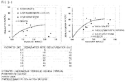
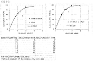
FIG. 2 shows graphs and tables showing relationships between desalination and desulfurization agents and desalination and desulfurization performance. -
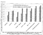
FIG. 3-1 is a graph showing relationships between various types of desalination and desulfurization agents and desalination and desulfurization performance (temperature: 550°C). -
FIG. 3-2 is a graph showing relationships between various types of desalination and desulfurization agents and desalination and desulfurization performance (temperature: 600°C) . -
FIG. 3-3 is a graph showing relationships between various types of desalination and desulfurization agents and desalination and desulfurization performance (temperature: 650°C) . - An embodiment of the present invention will be shown with reference to the accompanying drawings. However, this does not limit the present invention.
- First, a gasification power generation system will be described according to
FIG. 1 . - The gasification power generation system includes a
gasification furnace 1 that performs partial combustion gasification of a gasification material, abag filter 3 that is placed downstream of thegasification furnace 1 and removes dust from the gasified gas coming out of the furnace, a CO2 absorption and reforming furnace 4 that is placed downstream of thebag filter 3 and performs a reforming treatment of the gas having been subjected to dust removal, and apower generation facility 5 that is placed downstream of the CO2 absorption and reforming furnace 4 and performs power generation by utilizing a reformed gas coming out of the furnace. - In a flow path from the
gasification furnace 1 to thebag filter 3, acyclone 2 is placed, and to a flow path upstream of thecyclone 2, a cyclone upstreamadditive supply line 6 for supplying an additive having desalination and desulfurization functions and preferably further having a CO2 removal function from anadditive container 8 is connected. Further, a cyclone downstream additive supply line 7 for supplying an additive having desalination and desulfurization functions and preferably further having a CO2 removal function from anadditive tank 10 to a flow path from thecyclone 2 to thebag filter 3 is provided. - To each of the starting end portions of the cyclone upstream
additive supply line 6 and the cyclone downstream additive supply line 7, a carrier gas line 9 is connected from thepower generation facility 5 via a low-temperature boiler 13, adehumidifier 14, apressure increasing machine 15, and atank 16. - To immediately upstream of a CO2 absorbent-filled layer of the CO2 absorption and reforming furnace 4, an oxygen or
air supply line 19 for switching the flow of oxygen or air for increasing the temperature of a reforming furnace to the CO2 absorbent-filled layer when the amount of absorbed CO2 has reached saturation is connected. Thisline 19 generally supplies oxygen or air for increasing the temperature immediately upstream of a catalyst-filled layer of the CO2 absorption and reforming furnace 4. - Next, a method for removing acid components at high temperature in a gasification power generation method according to the present invention will be specifically described for each step with reference to the flow diagram of
FIG. 1 . - A gasification material such as waste, RDF, or a wood chip is subjected to partial combustion gasification in the
gasification furnace 1. To thegasification furnace 1, oxygen and water vapor are supplied from the bottom of the furnace. - The gasified gas coming out of the top of the
gasification furnace 1 is sent to thecyclone 2, and particles in the gasified gas are separated into a coarse powder having an average particle diameter of 100 µm or more and a fine powder having an average particle diameter less than 100 µm. The temperature of the gas coming into thecyclone 2 is 700°C or lower, preferably 550 to 650°C, and the temperature of the gas coming out of thecyclone 2 is 550 to 650°C. - An additive having desalination and desulfurization functions is blown into the flow path upstream of the
cyclone 2 from the cyclone upstreamadditive supply line 6. This additive preferably also has CO2 absorption and removal functions in addition to the desalination and desulfurization functions. This is a material that can be converted into a chloride or a sulfate at 700°C or lower, and is preferably selected from the group consisting of burnt dolomite, hydrated lime, sodium aluminate, and sodium bicarbonate. The average particle diameter of the additive is preferably from 100 to 1000 µm, more preferably from 300 to 600 µm. Burnt dolomite is preferred from the viewpoint of cost, and sodium aluminate is preferred from the viewpoint of desalination and desulfurization rates. In this embodiment, burnt dolomite having an average particle diameter of several hundreds of micrometers was supplied upstream of the cyclone from theadditive container 8 through theline 6. - By blowing the additive having desalination and desulfurization functions preferably also having CO2 absorption and removal functions into the flow path upstream of the
cyclone 2, the gasified gas is subjected to a desalination and desulfurization treatment and preferably can be subjected to a decarbonation treatment, and also a self-cleaning action of dust or tar adhered to the inside of thecyclone 2 can be performed, and the pressure loss in the bag filter downstream is suppressed, and the operation thereof can be carried out without any troubles. By the cyclone, all or part of the coarse powder additive having an average particle diameter of 100 to 1000 µm, dust, and tar are recovered in a bottom portion, and this recovered material is supplied to thegasification furnace 1 together with the gasification material. By doing this, reforming of tar in the CO2 absorption and reforming furnace 4 downstream can be complemented. - Subsequently, the gasified gas having been subjected to coarse powder removal coming out of the
cyclone 2 is sent to thebag filter 3 that performs a dust removal treatment of the gas. The gasified gas having been subjected to coarse powder removal contains particles having an average particle diameter less than 100 µm. - An additive having desalination and desulfurization functions is blown into the flow path to the
bag filter 3 from thecyclone 2 through the cyclone downstream additive supply line 7. This additive preferably also has CO2 absorption and removal functions in addition to the desalination and desulfurization functions. This additive is a material that can be converted into a chloride or a sulfate at 700°C or lower, and is preferably selected from the group consisting of burnt dolomite, hydrated lime, sodium aluminate, and sodium bicarbonate. The average particle diameter of the additive is preferably 20 µm or less, more preferably 15 µm or less. Burnt dolomite is preferred from the viewpoint of cost, and sodium aluminate is preferred from the viewpoint of desalination and desulfurization rates. The cyclone downstream additive and the cyclone upstream additive may be of the same type or different type. In this embodiment, burnt dolomite having an average particle diameter of 20 µm or less was supplied downstream of the cyclone from theadditive tank 10 through the cyclone downstream additive supply line 7. - By blowing the additive having desalination and desulfurization functions preferably also having CO2 absorption and removal functions into the flow path downstream of the
cyclone 2, the gasified gas having been subjected to coarse powder removal is subjected to a desalination and desulfurization treatment and preferably can be subjected to a decarbonation treatment. In particular, by the desalination and desulfurization treatment, the service life of a Ni-based reforming catalyst that is commonly used in the CO2 absorption and reforming furnace 4 downstream can be extended. - The average particle diameter of the additive is preferably 20 µm or less so as to enhance the effect of desalination and desulfurization. A known filter aid can also be used in combination with the cyclone downstream additive.
- The average particle diameter of particles is a value measured by a laser diffraction particle size distribution analyzer.
- In this embodiment, as the
bag filter 3, a precoat bag filter is used for preventing adhesion of dust containing a tar component to a filter cloth and enhancing the peelability of a cake layer on the surface of the filter cloth. The temperature of the gas coming into the precoat bag filter is 550 to 650°C, and the temperature of the gas coming out of the bag filter is decreased to about 540 to 640°C due to heat dissipation or the like. When the pressure loss in the precoat bag filter is increased, the cake layer on the surface of the filter cloth is wiped off by a pulse jet system, and thereafter, the cyclone downstream additive or a material using a filter aid in combination with the additive is precoated on the surface of the filter cloth in a short time. The pressure loss during precoating is targeted at 0.5 to 0.6 kPa. The wiping off of the cake layer on the surface of the filter cloth is performed when the pressure loss is preferably within a range of 1.5 to 1.8 kPa (153.0 to 183.5 mmH2O). - As for the amount of the precoat, an amount of 3 equivalents to the amount of HCl+SO2 in the gas is blown into for about 20 minutes. As a guide, one cycle is determined to be about 3.5 hours which is the sum of a time required for precoating and a steady operation time. The wiping off by the pulse jet is preferably performed by control of the pressure loss of the bag.
- The gasified gas is sent to the CO2 absorption and reforming furnace 4 after being subjected to dust removal by the
bag filter 3. A CO2 absorbent is filled in an upper portion of the CO2 absorption and reforming furnace 4, and a reforming catalyst is filled in a lower portion thereof. As the CO2 absorbent, a compound which is carbonated by CO2 absorption in a temperature range of 450 to 700°C, preferably 540 to 640°C and causes decarbonation, that is, CO2 separation in a temperature range of 800 to 950°C, preferably 850 to 900°C is used. Examples of the CO2 absorbent include CaO, Ca(OH)2, and burnt dolomite (CaO·MgO), and in this embodiment, CaO was used as the CO2 absorbent. - The CO2 separation from the CO2 absorbent by switching of the flow path of the oxygen or
air supply line 19 will be described. - 1) The temperature range of the gasified gas during normal CO2 absorption operation is 450 to 700°C, preferably 540 to 640°C, and the temperature of the CO2 absorbent is also maintained in this temperature range. When CaO is used as the CO2 absorbent, CO2 is absorbed or removed by the absorbent according to the following reaction.
CaO + CO2 → CaCO3
In this manner, by removing CO2 in the gasified gas, the following shift reaction is likely to proceed to the right-hand side.
CO + H2O → CO2 + H2
In this state, oxygen or air for increasing the temperature is supplied immediately upstream of the reforming catalyst layer by the normal flow path of the oxygen orair supply line 19. - 2) When the amount of absorbed CO2 has reached saturation, oxygen or air used for increasing the temperature of the catalyst-filled layer during normal operation is supplied immediately upstream of the CO2 absorbent-filled layer by switching the flow path of the oxygen or
air supply line 19, and the temperature of the absorbent is increased within a temperature range of 800 to 950°C, preferably 850 to 900°C. In this temperature range, a carbonated material of the CO2 absorbent is thermally decomposed and CO2 is separated from the absorbent. - An increase in temperature due to injection of oxygen or air in the CO2 absorption and reforming furnace 4 is caused by oxidation reaction heat of a tar component, H2, CO, or CH4.
- When the amount of absorbed CO2 of the CO2 absorbent has reached saturation, the value of a downstream CO2 analyzer 18 which is provided downstream of a high-
temperature boiler 11 and shows a CO2 concentration in the gasified gas starts to increase, and therefore, as described above, oxygen or air used for increasing the temperature is supplied immediately upstream of the CO2 absorbent-filled layer. When the temperature of the absorbent is increased within a temperature range of 800 to 950°C, preferably 850 to 900°C, CaCO3 starts to be decomposed, and generated CO2 flows downstream. At that time, the concentration of CO2 in the gasified gas is temporarily increased, and therefore, the shift reaction is not accelerated. When the CO2 concentrations shown by each of an upstream CO2 analyzer 17 which is provided upstream of the CO2 absorption and reforming furnace 4 and shows a CO2 concentration in the gasified gas and the downstream CO2 analyzer 18 come close to each other, the flow of oxygen or air for increasing the temperature is returned immediately upstream of the reforming catalyst layer, and the temperature of the catalyst-filled layer is decreased to a range of 450 to 700°C, preferably 540 to 640°C. - Thereafter, the operations of 1) and 2) described above are repeated.
- By removing CO2 with the CO2 absorbent-filled layer, the following shift reaction in the reforming catalyst-filled layer can be accelerated.
- When assuming toluene as a representative example of tar, main reactions occurring in the CO2 absorption and reforming furnace 4 are as follows.
- i)
C7H8 + 9 O2 → 7 CO2 + 4 H2O
oxidation reaction - ii)
C7H8 + 7 H2O → 7 CO + 11 H2
reforming reaction - iii)
CO + H2O → CO2 + H2
shift reaction - iv) Other than these, when oxygen is present excessively, an oxidation reaction of H2, CO, CH4, or the like also occurs.
- A high temperature gas at 850 to 900°C coming out of a bottom portion of the CO2 absorption and reforming furnace 4 is sent to the high-
temperature boiler 11 and subjected to a heat recovery treatment there, and thereafter sent to acooling tower 12 at a temperature of 170 to 180°C. In thecooling tower 12, an aqueous NaOH solution is circulated, and by this, CO2 in the gasified gas is absorbed and a generated Na2CO3 salt is recovered and removed. Accordingly, a greenhouse gas is not discharged. - A low temperature gas at a temperature of 55 to 60°C coming out of the
cooling tower 12 is sent to thepower generation facility 5 provided with a gas turbine or a gas engine and utilized for power generation there. - The gas discharged from the
power generation facility 5 at a temperature of 400°C is subjected to a heat recovery treatment by the low-temperature boiler 13, and thereafter partially released to the atmosphere at 170 to 180°C and the remainder is sent to each of the starting end portions of the cyclone upstreamadditive supply line 6 and the cyclone downstream additive supply line 7 via thedehumidifier 14, thepressure increasing machine 15, and thetank 16 through the carrier gas line 9, and utilized as a carrier gas (gas temperature of 50°C) for the cyclone upstream additive and the cyclone downstream additive. The oxygen concentration in this gas is about 1 to 2 vol%, and the injection ratio of the carrier gas to an outlet gas of the gasification furnace is 1/15 to 1/30, and therefore, a decrease in lower heating value (LHV) due to combustion of a combustible gas is not caused. - Next, experimental examples of the present invention will be shown.
- Experiments were performed by changing respective conditions in the system shown in
FIG. 1 that performs power generation utilizing a combustible gas obtained by gasification and reforming of waste. One example of a composition of the outlet gas of thegasification furnace 1 is shown in Table 1, the temperatures of thegasification furnace 1 and the CO2 absorption and reforming furnace 4 and the air ratio to each outlet gas are shown in Table 2, relationships between desalination and desulfurization agents and desalination and desulfurization performance are shown inFIG. 2 , the air ratio to the outlet gas of thepower generation facility 5 is shown in Table 3, relationships between various kinds of desalination and desulfurization agents and desalination and desulfurization performance are shown in Table 4 andFIG. 3 , and results of thermodynamic equilibrium calculation for generation and decomposition of calcium carbonate (CaO + CO2 ↔ CaCO3) are shown in Table 5. - According to Table 5, in the CO2 absorption tower, 96.98% CO2 is absorbed and removed at 600°C with inlet CO2 at 8.1% according to the equilibrium calculation (at 650°C, 89.37%). Further, when the temperature of the absorption tower is increased to 850°C, decomposition occurs until the outlet CO2 concentration becomes 38.59% (at 900°C, decomposition occurs until the outlet CO2 concentration becomes 79.48%).
[Table 1] Composition of exhaust gas from outlet of gasification furnace (one example) N2 vol%-wet 39.8 O2 vol%-wet 1 H2 vol%-wet 0.8 H2O vol%-wet 44.5 CO2 vol%-wet 8.1 CO vol%-wet 2.8 CH4 vol%-wet 0.5 Other H.C vol%-wet 0.9 HCl ppm-wet 3.4 SO2 ppm-wet 13.5 H2S ppm-wet 0.1 Total vol%-wet 98.40 
[Table 3] GE outlet gas vs. GE air ratio GE air ratio 1.1 1.2 1.3 1.4 Nm3/h vol% Nm3/h vol% Nm3/h vol% Nm3/h vol% CO2 17565 13.96 17565 13.48 17565 13.04 17565 12.64 O2 1135 0.90 2064 1.58 2994 2.22 3924 2.82 N2 81106 64.44 84604 64.94 88103 65.40 91601 65.83 H2O 26054 20.70 26054 20.00 26054 19.34 26054 18.72 Total gas 125860 100 130288 100 134717 100 139145 100 [Table 4] Desalination and desulfurization agent Desalination and desulfurization performance (reaction equivalent ratio = 2.0) Name Chemical formula 550°C 600°C 650°C Desalination rate (%) Desulfurization rate (%) Desalination rate (%) Desulfurization rate (%) Desalination rate (%) Desulfurization rate (%) sodium bicarbonate NaHCO3 80 61 69 63 62 69 hydrated lime Ca(OH)2 - - - - 37 57 lime CaCO3 - - - - 27 56 dolomite CaCO3·MgCO3 - - - - 47 77 light burnt dolomite CaCO3·MgO - - - - 47 77 sodium aluminate NaAlO2 - - - - 64 78 3.2-8.5 NaAlO2-supporting γ-alumina 3.2-8.5 NaAlO2/γ-Al2O3 - - - - 79 92 40% NaAlO2-supporting γ- alumina 40% NaAlO2/γ-Al2O3 - - - - 89 93 
Claims (10)
- A method for removing acid components at high temperature in a gasification power generation method characterized in that in a gasification power generation system including a gasification step of performing partial combustion gasification of a gasification material, a cyclone treatment step of performing a coarse powder collection treatment of a gasified gas coming out of the gasification step, a bag filter treatment step of performing a dust removal treatment of the gasified gas having been subjected to coarse powder removal coming out of the cyclone treatment step, a CO2 absorption and reforming step of performing a CO2 absorption and reforming treatment of the gasified gas having been subjected to dust removal coming out of the bag filter treatment step, and a power generation step of performing power generation by utilizing a reformed gas coming out of the CO2 absorption and reforming step,
after the gasification step but before the cyclone treatment step, a cyclone upstream additive having desalination and desulfurization functions is supplied to the gasified gas using a gas coming out of the power generation step after recovering heat as an additive carrier gas, and
a CO2 absorbent used in the CO2 absorption and reforming step is allowed to absorb CO2 in a gas temperature range of 450 to 700°C, and when the amount of absorbed CO2 has reached saturation, the flow of oxygen or air for increasing the temperature of a reforming catalyst layer is switched immediately upstream of a CO2 absorbent-filled layer, and the temperature of the absorbent-filled layer is increased within a temperature range of 800 to 950°C to separate CO2 from the absorbent. - The method for removing acid components at high temperature in a gasification power generation method according to claim 1, wherein the cyclone upstream additive also has CO2 absorption and removal functions.
- The method for removing acid components at high temperature in a gasification power generation method according to claim 1 or 2, characterized in that the cyclone upstream additive has an average particle diameter of 100 to 1000 µm.
- The method for removing acid components at high temperature in a gasification power generation method according to any one of claims 1 to 3, characterized in that the cyclone upstream additive is selected from the group consisting of burnt dolomite, hydrated lime, sodium aluminate, and sodium bicarbonate.
- The method for removing acid components at high temperature in a gasification power generation method according to any one of claims 1 to 4, characterized in that after the cyclone treatment step but before the bag filter treatment step, an additive which is a cyclone downstream additive that has desalination and desulfurization functions and may be the same as or different from the cyclone upstream additive and is selected from the group consisting of burnt dolomite, hydrated lime, sodium aluminate, and sodium bicarbonate is supplied to the gasified gas having been subjected to coarse powder removal using a gas coming out of the power generation step after recovering heat as an additive carrier gas.
- The method for removing acid components at high temperature in a gasification power generation method according to any one of claims 1 to 5, characterized in that in the cyclone treatment step, a coarse powder containing the additive is collected, and the collected coarse powder is supplied to the gasification step together with the gasification material.
- The method for removing acid components at high temperature in a gasification power generation method according to any one of claims 1 to 6, characterized in that the CO2 absorbent used in the CO2 absorption and reforming step is selected from the group consisting of CaO, Ca(OH)2, and burnt dolomite.
- The method for removing acid components at high temperature in a gasification power generation method according to any one of claims 1 to 7, characterized in that after the heat recovery treatment, the reformed gas is subjected to a CO2 absorption treatment using an aqueous NaOH solution, and generated Na2CO3 is recovered and removed.
- A device for removing acid components at high temperature in a gasification power generation system, characterized in that in a gasification power generation system including a gasification furnace that performs partial combustion gasification of a gasification material, a cyclone that is placed downstream of the gasification furnace and performs a coarse powder collection treatment of a gasified gas coming out of the furnace, a bag filter that is placed downstream of the cyclone and performs a dust removal treatment of the gasified gas having been subjected to coarse powder removal coming out of the cyclone, a CO2 absorption and reforming furnace that is placed downstream of the bag filter and performs a CO2 absorption and reforming treatment of the gasified gas having been subjected to dust removal coming out of the bag filter, and a power generation facility that is placed downstream of the CO2 absorption and reforming furnace and performs power generation by utilizing a reformed gas coming out of the furnace,
a cyclone upstream additive supply line for supplying an additive having desalination and desulfurization functions to a flow path to the cyclone from the gasification furnace is provided, a carrier gas line coming from the power generation facility is connected to the supply line, and an oxygen or air supply line for switching oxygen or air for increasing the temperature of the reforming furnace to a CO2 absorbent-filled layer when the amount of absorbed CO2 has reached saturation is connected immediately upstream of the CO2 absorbent-filled layer of the CO2 absorption and reforming furnace. - The device for removing acid components at high temperature in a gasification power generation system according to claim 9, characterized in that
a cyclone downstream additive supply line for supplying an additive having desalination and desulfurization functions to a flow path to the bag filter from the cyclone is provided, and a carrier gas line coming from the power generation facility is connected to the supply line.
Applications Claiming Priority (2)
| Application Number | Priority Date | Filing Date | Title |
|---|---|---|---|
| JP2016224971A JP6681316B2 (en) | 2016-11-18 | 2016-11-18 | Method and apparatus for removing acid component at high temperature in gasification power generation system |
| PCT/JP2017/032202 WO2018092391A1 (en) | 2016-11-18 | 2017-09-07 | Method for removing acid components at high temperature in gasification power generation system, and device therefor |
Publications (2)
| Publication Number | Publication Date |
|---|---|
| EP3543318A1 true EP3543318A1 (en) | 2019-09-25 |
| EP3543318A4 EP3543318A4 (en) | 2020-06-03 |
Family
ID=62146420
Family Applications (1)
| Application Number | Title | Priority Date | Filing Date |
|---|---|---|---|
| EP17872759.0A Withdrawn EP3543318A4 (en) | 2016-11-18 | 2017-09-07 | METHOD FOR HIGH TEMPERATURE REMOVAL OF ACID COMPONENTS IN A GASIFICATION ENERGY GENERATION SYSTEM, AND ASSOCIATED DEVICE |
Country Status (5)
| Country | Link |
|---|---|
| EP (1) | EP3543318A4 (en) |
| JP (1) | JP6681316B2 (en) |
| CN (1) | CN109983102A (en) |
| PH (1) | PH12019501091A1 (en) |
| WO (1) | WO2018092391A1 (en) |
Families Citing this family (4)
| Publication number | Priority date | Publication date | Assignee | Title |
|---|---|---|---|---|
| CN110938472B (en) * | 2019-12-04 | 2021-09-24 | 新奥科技发展有限公司 | Gasification furnace and coal gasification method |
| CN112391210B (en) * | 2020-11-17 | 2021-06-18 | 滨州中科催化技术有限公司 | Coke oven gas purification system |
| CN114921268B (en) * | 2022-05-23 | 2025-04-01 | 西安西矿环保科技有限公司 | A device and method for purifying high-temperature dusty oil and gas from pulverized coal pyrolysis and recovering semi-coke |
| CN120059808B (en) * | 2025-04-28 | 2025-08-12 | 陕西陕煤新型能源双碳科技有限公司 | Coke oven gas pretreatment method and system |
Family Cites Families (15)
| Publication number | Priority date | Publication date | Assignee | Title |
|---|---|---|---|---|
| JPS553761A (en) | 1978-06-21 | 1980-01-11 | Yamazaki Koki Kk | Manufacturing of shaped fish paste |
| JPH086101B2 (en) * | 1986-11-27 | 1996-01-24 | バブコツク日立株式会社 | Coal gasification desulfurization method |
| RU2270849C2 (en) * | 1998-11-05 | 2006-02-27 | Ибара Корпорейшн | System producing electric power with the help of gasification of combustibles |
| JP2002130628A (en) | 2000-10-27 | 2002-05-09 | Takuma Co Ltd | Pyrolysis gas purification equipment for pyrolysis melting and combustion equipment |
| JP2006037012A (en) | 2004-07-29 | 2006-02-09 | Takuma Co Ltd | Gasification power generation system and gasification power generation method |
| US20100301273A1 (en) * | 2008-01-14 | 2010-12-02 | Wlodzimierz Blasiak | Biomass gasification method and apparatus for production of syngas with a rich hydrogen content |
| CN101525118B (en) * | 2008-03-07 | 2010-12-22 | 周开根 | Gasification process for producing synthesis gas from garbage and biomass raw materials |
| JP2009242714A (en) * | 2008-03-31 | 2009-10-22 | Mitsui Eng & Shipbuild Co Ltd | Waste gasification disposal system |
| JP2011202119A (en) * | 2010-03-26 | 2011-10-13 | Mitsui Eng & Shipbuild Co Ltd | Gasification system |
| CN103249816B (en) * | 2010-12-24 | 2016-05-18 | 株式会社Ihi | Generate reforming method and the device of gas |
| JP2013241923A (en) * | 2012-05-23 | 2013-12-05 | Babcock Hitachi Kk | Gasification power generation system of carbon-based fuel |
| CA2876023C (en) * | 2012-07-19 | 2020-07-28 | Research Triangle Institute | Regenerable sorbent for carbon dioxide removal |
| KR101398191B1 (en) * | 2013-02-27 | 2014-05-27 | (주)대우건설 | High temperature purification system for simultaneously removing desulphurization and desalination in synthetic gas using fixed bed single reactor |
| CN103242922A (en) * | 2013-05-31 | 2013-08-14 | 青岛新奥胶城燃气有限公司 | Method for preparing fuel gas by burning biomass |
| CN103820183B (en) * | 2014-02-26 | 2016-08-31 | 山西华兆煤化工有限责任公司 | A kind of oven gas directly mends the method for carbon dioxide synthetic natural gas |
-
2016
- 2016-11-18 JP JP2016224971A patent/JP6681316B2/en active Active
-
2017
- 2017-09-07 EP EP17872759.0A patent/EP3543318A4/en not_active Withdrawn
- 2017-09-07 WO PCT/JP2017/032202 patent/WO2018092391A1/en not_active Ceased
- 2017-09-07 CN CN201780070958.XA patent/CN109983102A/en active Pending
-
2019
- 2019-05-16 PH PH12019501091A patent/PH12019501091A1/en unknown
Also Published As
| Publication number | Publication date |
|---|---|
| JP6681316B2 (en) | 2020-04-15 |
| WO2018092391A1 (en) | 2018-05-24 |
| EP3543318A4 (en) | 2020-06-03 |
| CN109983102A (en) | 2019-07-05 |
| JP2018080299A (en) | 2018-05-24 |
| PH12019501091A1 (en) | 2019-12-11 |
Similar Documents
| Publication | Publication Date | Title |
|---|---|---|
| AU2009308404B2 (en) | Process for decontaminating syngas | |
| TWI491726B (en) | The method of gas purification, coal gasification plant and shift catalyst | |
| AU2008286391A1 (en) | Cooled NaOH flue gas scrubbing prior to CO2 removal | |
| US20070092427A1 (en) | Pre-treatment of lime-based sorbents using hydration | |
| CA2543984C (en) | Reactivation of lime-based sorbents by co2 shocking | |
| JP6681316B2 (en) | Method and apparatus for removing acid component at high temperature in gasification power generation system | |
| KR100278949B1 (en) | Systems and methods for removing sulfur species from hot gases from coal | |
| US9238208B2 (en) | CO shift reaction apparatus and gasification gas refining system | |
| US9901876B1 (en) | Reclaiming useful products from exhaust gas clean-up system | |
| TW533265B (en) | Using shifted syngas to regenerate SCR type catalyst | |
| JP4775858B2 (en) | Method for regenerating copper-based absorbent and method for removing mercury from source gas | |
| JPH11210489A (en) | Gasification power generation method and gasification power generation facility | |
| JP2003534897A (en) | Method and apparatus for regenerating spent absorbent generated in heat generator flue gas treatment | |
| JP4594239B2 (en) | Gas purification system and gas purification method | |
| KR101322369B1 (en) | Hot gas clean-up system and method for removing pollutants in synthesis gas | |
| JPH1119468A (en) | Gas purification | |
| CN104507572A (en) | Co shift catalyst, co shift reactor, and method for purifying gasification gas | |
| JP2008045017A (en) | Gas purification apparatus and method, gasification system, gasification power generation system | |
| EP0375048B1 (en) | Method and device for desulphurising gas | |
| JP2009242714A (en) | Waste gasification disposal system | |
| JPH01199622A (en) | Dry desulfurization method for coal gas | |
| JP2009056415A (en) | Halide remover | |
| JPH0841467A (en) | Coal gasification plant product gas purification method | |
| JP4098425B2 (en) | Gas purification method and apparatus for black liquor gasification power generation system | |
| JP2006241229A (en) | Gasification system |
Legal Events
| Date | Code | Title | Description |
|---|---|---|---|
| STAA | Information on the status of an ep patent application or granted ep patent |
Free format text: STATUS: THE INTERNATIONAL PUBLICATION HAS BEEN MADE |
|
| PUAI | Public reference made under article 153(3) epc to a published international application that has entered the european phase |
Free format text: ORIGINAL CODE: 0009012 |
|
| STAA | Information on the status of an ep patent application or granted ep patent |
Free format text: STATUS: REQUEST FOR EXAMINATION WAS MADE |
|
| 17P | Request for examination filed |
Effective date: 20190614 |
|
| AK | Designated contracting states |
Kind code of ref document: A1 Designated state(s): AL AT BE BG CH CY CZ DE DK EE ES FI FR GB GR HR HU IE IS IT LI LT LU LV MC MK MT NL NO PL PT RO RS SE SI SK SM TR |
|
| AX | Request for extension of the european patent |
Extension state: BA ME |
|
| DAV | Request for validation of the european patent (deleted) | ||
| DAX | Request for extension of the european patent (deleted) | ||
| A4 | Supplementary search report drawn up and despatched |
Effective date: 20200504 |
|
| RIC1 | Information provided on ipc code assigned before grant |
Ipc: C10K 1/12 20060101ALI20200424BHEP Ipc: C10K 1/26 20060101ALI20200424BHEP Ipc: C10K 1/20 20060101AFI20200424BHEP Ipc: C10J 3/46 20060101ALI20200424BHEP Ipc: C10K 1/02 20060101ALI20200424BHEP Ipc: C10K 1/28 20060101ALI20200424BHEP Ipc: C10K 3/02 20060101ALI20200424BHEP |
|
| STAA | Information on the status of an ep patent application or granted ep patent |
Free format text: STATUS: THE APPLICATION IS DEEMED TO BE WITHDRAWN |
|
| 18D | Application deemed to be withdrawn |
Effective date: 20220401 |