EP3543136B1 - Synthetisiertes niederdruck-zapfluftschema für ein flugzeugzapfluftnetzwerk - Google Patents
Synthetisiertes niederdruck-zapfluftschema für ein flugzeugzapfluftnetzwerk Download PDFInfo
- Publication number
- EP3543136B1 EP3543136B1 EP19164358.4A EP19164358A EP3543136B1 EP 3543136 B1 EP3543136 B1 EP 3543136B1 EP 19164358 A EP19164358 A EP 19164358A EP 3543136 B1 EP3543136 B1 EP 3543136B1
- Authority
- EP
- European Patent Office
- Prior art keywords
- pressure
- bleed air
- low
- ecs
- pressure bleed
- Prior art date
- Legal status (The legal status is an assumption and is not a legal conclusion. Google has not performed a legal analysis and makes no representation as to the accuracy of the status listed.)
- Active
Links
Images


Classifications
-
- B—PERFORMING OPERATIONS; TRANSPORTING
- B64—AIRCRAFT; AVIATION; COSMONAUTICS
- B64D—EQUIPMENT FOR FITTING IN OR TO AIRCRAFT; FLIGHT SUITS; PARACHUTES; ARRANGEMENT OR MOUNTING OF POWER PLANTS OR PROPULSION TRANSMISSIONS IN AIRCRAFT
- B64D13/00—Arrangements or adaptations of air-treatment apparatus for aircraft crew or passengers, or freight space
- B64D13/02—Arrangements or adaptations of air-treatment apparatus for aircraft crew or passengers, or freight space the air being pressurised
-
- B—PERFORMING OPERATIONS; TRANSPORTING
- B64—AIRCRAFT; AVIATION; COSMONAUTICS
- B64D—EQUIPMENT FOR FITTING IN OR TO AIRCRAFT; FLIGHT SUITS; PARACHUTES; ARRANGEMENT OR MOUNTING OF POWER PLANTS OR PROPULSION TRANSMISSIONS IN AIRCRAFT
- B64D13/00—Arrangements or adaptations of air-treatment apparatus for aircraft crew or passengers, or freight space
- B64D13/06—Arrangements or adaptations of air-treatment apparatus for aircraft crew or passengers, or freight space the air being conditioned
-
- B—PERFORMING OPERATIONS; TRANSPORTING
- B64—AIRCRAFT; AVIATION; COSMONAUTICS
- B64D—EQUIPMENT FOR FITTING IN OR TO AIRCRAFT; FLIGHT SUITS; PARACHUTES; ARRANGEMENT OR MOUNTING OF POWER PLANTS OR PROPULSION TRANSMISSIONS IN AIRCRAFT
- B64D13/00—Arrangements or adaptations of air-treatment apparatus for aircraft crew or passengers, or freight space
- B64D13/06—Arrangements or adaptations of air-treatment apparatus for aircraft crew or passengers, or freight space the air being conditioned
- B64D13/08—Arrangements or adaptations of air-treatment apparatus for aircraft crew or passengers, or freight space the air being conditioned the air being heated or cooled
-
- F—MECHANICAL ENGINEERING; LIGHTING; HEATING; WEAPONS; BLASTING
- F02—COMBUSTION ENGINES; HOT-GAS OR COMBUSTION-PRODUCT ENGINE PLANTS
- F02C—GAS-TURBINE PLANTS; AIR INTAKES FOR JET-PROPULSION PLANTS; CONTROLLING FUEL SUPPLY IN AIR-BREATHING JET-PROPULSION PLANTS
- F02C6/00—Plural gas-turbine plants; Combinations of gas-turbine plants with other apparatus; Adaptations of gas-turbine plants for special use
- F02C6/04—Gas-turbine plants providing heated or pressurised working fluid for other apparatus, e.g. without mechanical power output
- F02C6/06—Gas-turbine plants providing heated or pressurised working fluid for other apparatus, e.g. without mechanical power output providing compressed gas
- F02C6/08—Gas-turbine plants providing heated or pressurised working fluid for other apparatus, e.g. without mechanical power output providing compressed gas the gas being bled from the gas-turbine compressor
-
- F—MECHANICAL ENGINEERING; LIGHTING; HEATING; WEAPONS; BLASTING
- F02—COMBUSTION ENGINES; HOT-GAS OR COMBUSTION-PRODUCT ENGINE PLANTS
- F02C—GAS-TURBINE PLANTS; AIR INTAKES FOR JET-PROPULSION PLANTS; CONTROLLING FUEL SUPPLY IN AIR-BREATHING JET-PROPULSION PLANTS
- F02C7/00—Features, components parts, details or accessories, not provided for in, or of interest apart form groups F02C1/00 - F02C6/00; Air intakes for jet-propulsion plants
- F02C7/08—Heating air supply before combustion, e.g. by exhaust gases
-
- F—MECHANICAL ENGINEERING; LIGHTING; HEATING; WEAPONS; BLASTING
- F02—COMBUSTION ENGINES; HOT-GAS OR COMBUSTION-PRODUCT ENGINE PLANTS
- F02C—GAS-TURBINE PLANTS; AIR INTAKES FOR JET-PROPULSION PLANTS; CONTROLLING FUEL SUPPLY IN AIR-BREATHING JET-PROPULSION PLANTS
- F02C9/00—Controlling gas-turbine plants; Controlling fuel supply in air- breathing jet-propulsion plants
- F02C9/16—Control of working fluid flow
- F02C9/18—Control of working fluid flow by bleeding, bypassing or acting on variable working fluid interconnections between turbines or compressors or their stages
-
- B—PERFORMING OPERATIONS; TRANSPORTING
- B64—AIRCRAFT; AVIATION; COSMONAUTICS
- B64D—EQUIPMENT FOR FITTING IN OR TO AIRCRAFT; FLIGHT SUITS; PARACHUTES; ARRANGEMENT OR MOUNTING OF POWER PLANTS OR PROPULSION TRANSMISSIONS IN AIRCRAFT
- B64D13/00—Arrangements or adaptations of air-treatment apparatus for aircraft crew or passengers, or freight space
- B64D13/06—Arrangements or adaptations of air-treatment apparatus for aircraft crew or passengers, or freight space the air being conditioned
- B64D2013/0603—Environmental Control Systems
- B64D2013/0618—Environmental Control Systems with arrangements for reducing or managing bleed air, using another air source, e.g. ram air
-
- Y—GENERAL TAGGING OF NEW TECHNOLOGICAL DEVELOPMENTS; GENERAL TAGGING OF CROSS-SECTIONAL TECHNOLOGIES SPANNING OVER SEVERAL SECTIONS OF THE IPC; TECHNICAL SUBJECTS COVERED BY FORMER USPC CROSS-REFERENCE ART COLLECTIONS [XRACs] AND DIGESTS
- Y02—TECHNOLOGIES OR APPLICATIONS FOR MITIGATION OR ADAPTATION AGAINST CLIMATE CHANGE
- Y02T—CLIMATE CHANGE MITIGATION TECHNOLOGIES RELATED TO TRANSPORTATION
- Y02T50/00—Aeronautics or air transport
- Y02T50/50—On board measures aiming to increase energy efficiency
Definitions
- Exemplary embodiments pertain to the aircraft systems, and more specifically, to aircraft environmental control systems.
- An aircraft environmental control system typically utilizes bleed air from turbine engines to regulate various aircraft environments such as, for example, cooling and/or heating the aircraft flight decks, cabin, etc.
- Two types of bleed air sources available for use include a high-pressure bleed air source sometimes referred to High Pressure Port Bleed (HPPB), and low-pressure bleed air source sometimes referred to as Low Pressure Port Bleed (LPPB).
- HPPB High Pressure Port Bleed
- LPPB Low Pressure Port Bleed
- HPPB pressure may not reach required levels to maintain desired ECS operations when the engines operate at low power (e.g., during taxi operation, cruise operation or descent). Therefore, HPPB is typically used when the engines operate at low-power operating conditions.
- US 2018/057172 discloses, according to its abstract, a method and aircraft for providing bleed air to environmental control systems of an aircraft using a gas turbine engine, including determining a bleed air demand for the environmental control systems, selectively supplying low pressure and high pressure bleed air to the environmental control systems, wherein the selectively supplying is controlled such that the conditioned air stream satisfies the determined bleed air demand.
- an aircraft is provided as defined by claim 1.
- An aircraft ECS can operate using both LPPB provided from a low-pressure bleed port and HPPB provided from a high-pressure bleed port depending on the operating conditions of the engines.
- the aircraft ECS includes an airflow network having a low-pressure bleed port (sometimes simply referred to as a LPPB) for providing low-pressure bleed air during high-power engine operating conditions, and a high-pressure bleed port (sometimes simply referred to as a HPPB) for providing high-pressure bleed air during low-power engine operating conditions.
- Conventional airflow networks typically include a pressure sensor installed in the high-pressure bleed air duct so that an engine controller can control the engine power and acceleration.
- the HPPB pressure (also known the engine compressor pressure) signal can be transmitted to the ECS Controller via digital data buses for controlling the ECS.
- LPPB pressure (also known as P2.7 pressure) sensors are traditionally not relied upon for engine control and hence they are not utilized in the engine control system.
- the engine controller can be constructed as a Full Authority Digital Engine Control (FADEC).
- FADEC Full Authority Digital Engine Control
- LPPB pressure sensors could be justified for the ECS control system, they may not be installed for cost and reliability reasons. Without the pressure sensors installed in the LPPB duct, conventional airflow networks may not effectively determine the presence of operating conditions that allow for reestablishing the low-pressure bleed air duct after activating the high-pressure bleed air duct.
- an LPPB pressure sensor would not indicate what the LPPB pressure would be while still operating from the HPPB.
- One or more non-limiting embodiments described herein provide an aircraft environmental control system that executes a synthesized low-pressure bleed air pressure scheme.
- the synthesized low-pressure bleed air scheme synthesizes or calculates an accurate pressure value associated with the low-pressure bleed air duct had the engine been providing bleed air from the LPPB instead of the HPPB.
- the aircraft environmental control system can switch to the low-pressure bleed air duct when pressure sensor associated with the high-pressure bleed air indicates that the engine power has reached levels where the low-pressure bleed air can properly operate the ECS.
- the design philosophy is that the ECS controller selects the LPPB whenever possible. When the LPPB pressure is not adequate to meet the ECS flow requirements, then the ECS controller selects the HPPB. However, it is desirable to return to LPPB at the first opportunity to save on engine fuel costs and reduce engine wear.
- the ECS 50 includes an airflow network 100 and an ECS controller 150 configured to control the airflow network 100.
- the ECS 50 aims to perform air conditioning, while also assisting in cabin pressurization.
- the ECS 50 includes two airflow network Bleed Air Systems (BASs) 100, 160 and two packs 114, 130.
- BASs Air Systems
- the right BAS 160 is the mirror image of the left airflow network BAS 100.
- the aircraft 10 can also include a cross-bleed valve 18, which controls the bleed air source delivered within the ECS 50.
- the ECS 50 includes a left pack 114, and a right pack 130, and a cross-bleed valve 18.
- the cross-bleed valve opens a duct between the left engine and left pack, 12 and114, respectively, and the right engine and right pack, 12 and 130, respectively.
- the cross-bleed valve can be adjusted at any time (e.g., a controller) to control the bleed air delivered to the ECS 50, thereby allowing the ECS 50 to operating according to different modes as described in greater detail below.
- the ECS controller 150 adjusts the position of cross-bleed 18 to allow various ECS configurations such as
- the high-pressure bleed air network 102 ducting further includes a high-pressure bleed air shutoff valve 110.
- the high-pressure bleed air shutoff valve 110 selectively controls the output of the high-pressure bleed air network 102 ducting and the output of the low-pressure bleed air network 104 ducting.
- the high-pressure bleed air shutoff valve 110 can be opened such that the high-pressure bleed air 101 is delivered through the airflow network 100.
- a check valve 111 installed in the low-pressure bleed air network 104 ducting is forced closed, thereby blocking the low-pressure bleed air 103 from flowing through the airflow network 100.
- the pre-cooled air 109 passes through pressure regulating shutoff valve 116 and is output to bleed manifold 170 and is then delivered to an air conditioning unit 114, sometimes referred to as a pneumatic air cycle kit (pack)
- the airflow network 100 can also include a bleed manifold pressure sensor 118 and a bleed manifold temperature sensor 120 to provide temperature measurements and pressure measurements, respectively, associated with the bleed manifold 170. These feedback signals allow the ECS controller 150 to regulate the pressure of bleed manifold 170 using the pressure regulating valve 116 and the temperature of the bleed manifold 170 using ram air control valve 117.
- the bleed manifold pressure sensor 118 and/or bleed manifold temperature sensor 120 can be located at different locations than illustrated in FIG. 2 without departing from the scope of the invention.
- an electronic air data computer (ADC) 152 can be installed on the aircraft 10, and can operate to determine (e.g., calculate) ambient pressure (P amb ) and/or ambient temperature (T amb ) values.
- the pack 114 utilizes an air cycle machine which converts the pre-cooled air 109 into temperature-regulated air. Air output from the pack 114 is delivered to a mixing and distribution unit 131 which serves to mix air output from the pack 114 with cabin air. The mixed air can also be delivered to different zones of the aircraft 10. Although the airflow system 100 is illustrated with respect to a single left pack 114 and a single engine 12, it should be appreciated that airflow system can operate to control one or more additional packs 114 corresponding to one or more additional engines 12 of the aircraft 10.
- the ECS controller 150 can generate a control signal that adjusts a position of the high-pressure bleed air shutoff valve 110, thereby selectively controlling delivery of the high-pressure bleed air 101 and low-pressure bleed air 103 to the pack 114.
- the check valve 111 is automatically opened. Accordingly, high-pressure bleed air 101 is blocked from entering the output duct 106 while the low-pressure bleed air 103 is delivered to the output duct 106 and is ultimately used to provide bleed air to pack 114.
- the check valve 111 is automatically closed.
- the low-pressure bleed air 103 is blocked from entering the output duct 106 while the high-pressure bleed air 101 is delivered to the output duct 106 and is ultimately used to provide bleed air to the pack 114.
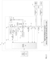
- the ECS controller 150 included in the ECS 50 executes a synthesized low-pressure bleed air scheme which effectively determines when to adjust (e.g., close) the high-pressure bleed air shutoff valve 110 after selecting the high-pressure bleed air 101 to be used to provide bleed air to the pack 114.
- the ECS controller 150 normally determines when to invoke the bleed selection transition from LPPB to HPPB. The ECS controller 150 determines the transition based on a comparison between the ECS minimum pressure required 204 (described below) and the actual pressure of the bleed manifold 170 measured by sensor 118. In at least one embodiment, the ECS minimum pressure required 204 corresponds to the pressure at the bleed manifold 170 which is at the PRSOV 116 Outlet. When the pressure is too low, the ECS controller 150 outputs a logic "1"/True signal from the high pressure bleed air selection evaluator 218, which commands the high-pressure bleed air shutoff valve 110 into the open position.
- the ECS controller 150 includes an ECS minimum pressure requirement and flow requirement schedule 200, an engine maker defined minimum Wcore flow schedule 207, an engine maker defined max P3/P2.7 ratio schedule 206, a low-pressure bleed air evaluator 212, and a percentage core flow evaluator 210.
- the ECS minimum pressure required 204 corresponds to the bleed manifold 170 pressure located at the outlet of the PRSOV 116.
- the engine maker defined max P3/P2.7 ratio schedule 206 generates an output of maximum P3/P2.7 209 based on an input minimum percent core flow 222 and the ratio of engine compressor absolute pressure (P3) reading 156 to an ambient pressure (P amb ) 158.
- the minimum percent core flow is the value of ECS required flow (Wdot 202) divided by W1min 208.
- the minimum Wcore flow schedule 207 and max P3/P2.7 ratio schedule 206 schedules are generated as follows. First, while using the HPPB as the source of bleed air, ECS bleed flow, power lever angle setting, ambient pressure and ambient temperature are input into a computer simulation of the engine. Then using the same input conditions except that the source of bleed air is LPPB, the computer simulation is run again. The process is repeated through hundreds of operating conditions.
- the low-pressure bleed air selection evaluator 212 generates an output that is "True” or "logic 1", for example, when the inputs are such that P2.7Synthesized (also known as a synthesized low-pressure pressure value) 220 is greater than a pressure threshold value, i.e., LP Threshold 231.
- LP Threshold 231 a pressure threshold value
- the LP threshold value is equal to the ECS minimum pressure required at a bleed manifold plus a correction for both the ducting and the second valve being full open, plus a hysteresis value.
Landscapes
- Engineering & Computer Science (AREA)
- Combustion & Propulsion (AREA)
- Chemical & Material Sciences (AREA)
- Pulmonology (AREA)
- General Health & Medical Sciences (AREA)
- Aviation & Aerospace Engineering (AREA)
- Health & Medical Sciences (AREA)
- General Engineering & Computer Science (AREA)
- Mechanical Engineering (AREA)
- Physics & Mathematics (AREA)
- Fluid Mechanics (AREA)
- Feedback Control In General (AREA)
- Fluid-Pressure Circuits (AREA)
- Combined Controls Of Internal Combustion Engines (AREA)
- Control Of Fluid Pressure (AREA)
Claims (6)
- Flugzeug, umfassend:mindestens ein Triebwerk (12), das so konfiguriert ist, dass es Hochdruckzapfluft und Niederdruckzapfluft erzeugt;ein Luftfahrzeug-Umgebungskontrollsystem, ECS, (50), das in Fluidverbindung mit dem mindestens einen Triebwerk steht, um die Hochdruckzapfluft und die Niederdruckzapfluft zu empfangen, wobei das ECS so konfiguriert ist, dass es einen vorhergesagten synthetisierten Niederdruckwert berechnet, der mit einem Niederdruckzapfluftkanal (104) verbunden ist, während es die Strömung der Niederdruckzapfluft durch den Niederdruckzapfluftkanal blockiert, aber immer noch Zapfluft aus dem ECS unter Verwendung der Hochdruckzapfluft ausgibt, und von der Ausgabe der Hochdruckzapfluft auf die Ausgabe der Niederdruckzapfluft durch das ECS umzuschalten, während die Strömung der Hochdruckzapfluft durch das ECS basierend auf dem vorhergesagten synthetisierten Niederdruckwert blockiert wird;ein Luftstromnetz (100), das einen Hochdruckzapfluftkanal (102) zur Aufnahme der Hochdruckzapfluft und einen Niederdruckzapfluftkanal (104) zur Aufnahme der Niederdruckzapfluft beinhaltet;mindestens ein Ventil (110), das die Hochdruckzapfluft empfängt und in einer ersten Stellung arbeitet, um den Fluss der Hochdruckzapfluft durch den Hochdruckzapfluftkanal zu steuern, und in einer zweiten Stellung, um den Fluss der Niederdruckzapfluft durch den Niederdruckzapfluftkanal zu steuern; undeinen Drucksensor, der so konfiguriert ist, dass er den Druck der Hochdruckzapfluft misst;eine elektronische ECS-Steuerung, die in Signalkommunikation mit dem Flugzeugnetzwerk (100) steht und so konfiguriert ist, dass sie einen vorbestimmten Plan von Zapfluftdruckverhältniswerten (P3/P2.7) zwischen simuliertem Triebwerkskompressordruck (P3), der einem Hochdruckzapfluftanschluss (HPPB) entspricht, und simulierter Niederdruckzapfluft (P2.7), die einem Niederdruckzapfanschluss (LPPB) entspricht, um einen synthetisierten Niederdruckwert (220) zu berechnen, der mit der Niederdruckzapfluft verbunden ist, während immer noch Zapfluft unter Verwendung der Hochdruckzapfluft bereitgestellt wird, und um das mindestens eine Ventil so zu steuern, dass es von der ersten Position in die zweite Position übergeht, um von der Lieferung der Hochdruckzapfluft auf die Niederdruckzapfluft durch das ECS umzuschalten, während die Strömung der Hochdruckzapfluft durch das ECS basierend auf dem synthetisierten Niederdruckwert (220) blockiert wird; undeinen Niederdruckzapfluft-Auswahlbewerter (212), der eine Ausgabe erzeugt, die "Wahr" ist, wenn die Eingaben so sind, dass der synthetisierte Niederdruckdruckwert größer als ein Druckschwellenwert ist,wobei der synthetisierte Niederdruckwert als der Druck der Hochdruckzapfluft geteilt durch einen Maximalwert der Zapfluftdruckverhältniswerte berechnet wird, undwobei ein maximaler Zapfluftdruckverhältniswert (P3/P2.7) basierend auf einem eingegebenen minimalen prozentualen Kerndurchfluss und einem Verhältnis des absoluten Drucks des Motorkompressors (P3) zu einem Umgebungsdruck (Pamb) bestimmt wird, wobei der minimale prozentuale Kerndurchfluss ein Wert des erforderlichen ECS-Durchflusses geteilt durch einen ausgegebenen minimalen Motorkernluftdurchfluss (W1 min) ist, der als ein minimaler Wcore-Durchflussplan definiert ist, der auf dem Umgebungsdruck (Pamb) und einem Verhältnis des absoluten Drucks des Motorkompressors (P3) zu dem Umgebungsdruck (Pamb) basiert.
- Flugzeug nach Anspruch 1, wobei die ECS-Steuerung den vorhergesagten synthetisierten Niederdruckwert mit einem Niederdruck (LP)-Schwellenwert vergleicht und das mindestens eine Ventil in die zweite Position anpasst, um die Niederdruckzapfluft auszugeben, wenn der vorhergesagte synthetisierte Niederdruckwert größer als der LP-Schwellenwert ist.
- Flugzeug nach Anspruch 2, wobei die ECS-Steuerung den vorhergesagten synthetisierten Niederdruckwert basierend auf einer erforderlichen Menge an Niederdruckzapfluft-Fähigkeit durch das mindestens eine Triebwerk, der Umgebungstemperatur, dem Umgebungsdruck, dem ECS-Betriebsmodus und einem gemessenen Druck einer Hochdruckzapfluft berechnet, während sie an einer Hochdruckzapföffnung (HPPB) arbeitet.
- Flugzeug nach einem der vorhergehenden Ansprüche, wobei das Flugzeug eine Vielzahl von Triebwerken beinhaltet und wobei das ECS so konfiguriert ist, dass es in einer Vielzahl von verschiedenen Betriebsmodi arbeitet, wobei ein erster Modus aus der Vielzahl von Betriebsmodi so konfiguriert ist, dass die Hochdruckzapfluft und die Niederdruckzapfluft von mindestens zwei Triebwerken aus der Vielzahl von Triebwerken erzeugt wird, und ein zweiter Betriebsmodus aus der Vielzahl von Betriebsmodi so konfiguriert ist, dass die Hochdruckzapfluft und die Niederdruckzapfluft von einem einzigen Triebwerk aus der Vielzahl von Triebwerken erzeugt wird.
- Flugzeug nach einem der vorhergehenden Ansprüche, wobei die Steuerung des ECS aktiv den erforderlichen ECS-Mindestdruckwert am Zapfverteiler und den LP-Schwellenwert an einer Niederdruckzapfanschluss (LPPB) basierend auf einem aktuellen Betriebsmodus des ECS bestimmt, während es über den Hochdruckzapfkanal arbeitet.
- Flugzeug nach Anspruch 5, wobei die ECS-Steuerung das mindestens eine Ventil in die erste Position anpasst, um die Hochdruckzapfluft als Reaktion darauf auszugeben, dass der erforderliche ECS-Mindestdruck am Zapfverteiler größer als ein Zapfverteilerdruck ist, und nach dem Aufrufen der ersten Position des Ventils das mindestens eine Ventil in die zweite Position zurückstellt, um die Niederdruckzapfluft als Reaktion darauf auszugeben, dass der vorhergesagte synthetisierte Niederdruckwert größer als der LP-Schwellenwert ist.
Applications Claiming Priority (1)
| Application Number | Priority Date | Filing Date | Title |
|---|---|---|---|
| US15/927,653 US11180259B2 (en) | 2018-03-21 | 2018-03-21 | Synthesized low-pressure bleed air scheme for aircraft bleed air network |
Publications (2)
| Publication Number | Publication Date |
|---|---|
| EP3543136A1 EP3543136A1 (de) | 2019-09-25 |
| EP3543136B1 true EP3543136B1 (de) | 2024-07-24 |
Family
ID=65904189
Family Applications (1)
| Application Number | Title | Priority Date | Filing Date |
|---|---|---|---|
| EP19164358.4A Active EP3543136B1 (de) | 2018-03-21 | 2019-03-21 | Synthetisiertes niederdruck-zapfluftschema für ein flugzeugzapfluftnetzwerk |
Country Status (3)
| Country | Link |
|---|---|
| US (1) | US11180259B2 (de) |
| EP (1) | EP3543136B1 (de) |
| CN (1) | CN110294131B (de) |
Families Citing this family (4)
| Publication number | Priority date | Publication date | Assignee | Title |
|---|---|---|---|---|
| FR3105300B1 (fr) * | 2019-12-24 | 2022-06-17 | Safran Aircraft Engines | Procédé de commande d’une vanne haute pression d’un système de prélèvement d’air d’un turboréacteur d’aéronef |
| CN111994286B (zh) * | 2020-08-26 | 2022-04-01 | 中国商用飞机有限责任公司 | 飞机环控系统混合腔温度控制方法和装置 |
| CN114060118B (zh) * | 2021-10-20 | 2022-09-23 | 中国航发四川燃气涡轮研究院 | 一种引气转换装置 |
| US20250223982A1 (en) * | 2024-01-08 | 2025-07-10 | The Boeing Company | Pneumatic System Flow Balancing Architecture and Method |
Family Cites Families (20)
| Publication number | Priority date | Publication date | Assignee | Title |
|---|---|---|---|---|
| US5590852A (en) * | 1993-08-31 | 1997-01-07 | Alliedsignal Inc. | Apparatus for controlling the partial pressure of oxygen in an aircraft cabin |
| US8220245B1 (en) * | 2005-08-03 | 2012-07-17 | Candent Technologies, Inc. | Multi spool gas turbine system |
| DE502008002475D1 (de) * | 2008-05-26 | 2011-03-10 | Siemens Ag | Verfahren zum Betreiben einer Gasturbine |
| US8016232B2 (en) | 2008-05-29 | 2011-09-13 | Honeywell International Inc. | Aircraft cabin pressure descent detection and control system and method |
| DE102010021890A1 (de) * | 2010-05-28 | 2011-12-01 | Airbus Operations Gmbh | Klimatisierungssystem für ein Flugzeug mit Hybrid-Betrieb |
| US8612063B2 (en) * | 2011-05-02 | 2013-12-17 | Honeywell International, Inc. | Temperature control setpoint offset for ram air minimization |
| US9957051B2 (en) | 2013-09-03 | 2018-05-01 | Hamilton Sundstrand Corporation | Method of operating a multi-pack environmental control system |
| US9382841B2 (en) | 2013-09-03 | 2016-07-05 | Hamilton Sundstrand Corporation | Aircraft environmental control system selectively powered by three bleed ports |
| GB201318572D0 (en) | 2013-10-21 | 2013-12-04 | Rolls Royce Plc | Pneumatic system for an aircraft |
| US9950798B2 (en) | 2014-03-03 | 2018-04-24 | The Boeing Company | Air conditioning system and methods of assembling the same |
| US9580180B2 (en) | 2014-03-07 | 2017-02-28 | Honeywell International Inc. | Low-pressure bleed air aircraft environmental control system |
| EP2937287B1 (de) * | 2014-04-24 | 2018-02-21 | Louis J. Bruno | Klimaregelungssystem mit shoestring-kreislauf zur maximierung der effizienz |
| US10583927B2 (en) * | 2014-10-09 | 2020-03-10 | The Boeing Company | Systems and methods for monitoring an air treatment assembly of a vehicle |
| US10011361B2 (en) | 2015-11-16 | 2018-07-03 | Textron Innovations Inc. | Aircraft environmental control system providing improved performance and backup temperature control |
| US20170233081A1 (en) * | 2016-02-13 | 2017-08-17 | Ge Aviation Systems Llc | Method and aircraft for providing bleed air to an environmental control system |
| US11377216B2 (en) * | 2016-08-23 | 2022-07-05 | Ge Aviation Systems Llc | Advanced method and aircraft for pre-cooling an environmental control system using a dual compressor four wheel turbo-machine |
| US10358221B2 (en) * | 2016-08-23 | 2019-07-23 | Ge Aviation Systems Llc | Hybrid method and aircraft for pre-cooling an environmental control system using a power generator four wheel turbo-machine |
| US20180057171A1 (en) * | 2016-08-23 | 2018-03-01 | Ge Aviation Systems, Llc | Advanced method and aircraft for pre-cooling an environmental control system using a three wheel turbo-machine |
| US20180057170A1 (en) * | 2016-08-23 | 2018-03-01 | Ge Aviation Systems, Llc | Enhanced method and aircraft for pre-cooling an environmental control system using a two wheel turbo-machine with supplemental heat exchanger |
| US10414505B2 (en) * | 2016-09-02 | 2019-09-17 | Embraer S.A. | Aircraft air conditioning system airflow regulation |
-
2018
- 2018-03-21 US US15/927,653 patent/US11180259B2/en active Active
-
2019
- 2019-03-20 CN CN201910211675.3A patent/CN110294131B/zh active Active
- 2019-03-21 EP EP19164358.4A patent/EP3543136B1/de active Active
Also Published As
| Publication number | Publication date |
|---|---|
| US11180259B2 (en) | 2021-11-23 |
| US20190291876A1 (en) | 2019-09-26 |
| CN110294131A (zh) | 2019-10-01 |
| CN110294131B (zh) | 2024-07-19 |
| EP3543136A1 (de) | 2019-09-25 |
Similar Documents
| Publication | Publication Date | Title |
|---|---|---|
| EP3543136B1 (de) | Synthetisiertes niederdruck-zapfluftschema für ein flugzeugzapfluftnetzwerk | |
| US6202403B1 (en) | Core compartment valve cooling valve scheduling | |
| US7959109B2 (en) | Dual valve apparatus for aircraft engine ice protection and related methods | |
| EP0607265B1 (de) | Kraftstoffsteuerungssystem mit geschlossenem regelkreis | |
| US5440490A (en) | Aircraft engine emergency control system | |
| US8016232B2 (en) | Aircraft cabin pressure descent detection and control system and method | |
| US7168254B2 (en) | Control logic for fuel controls on APUs | |
| US12305519B2 (en) | Turbine engine operational testing | |
| US4344141A (en) | Gas-turbine engine control | |
| CA1161527A (en) | Temperature trim/synchronizer system | |
| EP2489855B1 (de) | Regelungssystem für Zapfluft sowie Verfahren | |
| UA84280C2 (ru) | Способ управления потоком воздуха в газовой турбине и система для осуществления данного способа | |
| EP1880940A1 (de) | System und Verfahren zur Steuerung eines Verdichterstroms | |
| US6481210B1 (en) | Smart surge bleed valve system and method | |
| EP3712414B1 (de) | Druckluftsystem | |
| US8463496B2 (en) | Decoupling control architecture for pressure and flow controls in series | |
| EP3543148B1 (de) | Flugzeugklimaanlagensteuerungssystem mit ventildiagnose ohne positionsrückkopplung | |
| US20130039781A1 (en) | Anticipation logic for a surge control valve utilized with load compressor | |
| JPS63150435A (ja) | ガスタービンエンジンの制御装置及び方法 | |
| US10926883B2 (en) | Environmental control system including shared air source with balanced airflow output | |
| US20240280059A1 (en) | System and Method to Prevent Bleed Air Over-Extraction in Aircraft | |
| Lehle | Airbus A 330/340 environmental control system | |
| Patrick et al. | Air Supply System Approach for the Boeing Model 767 Airplane |
Legal Events
| Date | Code | Title | Description |
|---|---|---|---|
| PUAI | Public reference made under article 153(3) epc to a published international application that has entered the european phase |
Free format text: ORIGINAL CODE: 0009012 |
|
| STAA | Information on the status of an ep patent application or granted ep patent |
Free format text: STATUS: THE APPLICATION HAS BEEN PUBLISHED |
|
| AK | Designated contracting states |
Kind code of ref document: A1 Designated state(s): AL AT BE BG CH CY CZ DE DK EE ES FI FR GB GR HR HU IE IS IT LI LT LU LV MC MK MT NL NO PL PT RO RS SE SI SK SM TR |
|
| AX | Request for extension of the european patent |
Extension state: BA ME |
|
| STAA | Information on the status of an ep patent application or granted ep patent |
Free format text: STATUS: REQUEST FOR EXAMINATION WAS MADE |
|
| 17P | Request for examination filed |
Effective date: 20191216 |
|
| RBV | Designated contracting states (corrected) |
Designated state(s): AL AT BE BG CH CY CZ DE DK EE ES FI FR GB GR HR HU IE IS IT LI LT LU LV MC MK MT NL NO PL PT RO RS SE SI SK SM TR |
|
| STAA | Information on the status of an ep patent application or granted ep patent |
Free format text: STATUS: EXAMINATION IS IN PROGRESS |
|
| 17Q | First examination report despatched |
Effective date: 20201112 |
|
| GRAP | Despatch of communication of intention to grant a patent |
Free format text: ORIGINAL CODE: EPIDOSNIGR1 |
|
| STAA | Information on the status of an ep patent application or granted ep patent |
Free format text: STATUS: GRANT OF PATENT IS INTENDED |
|
| RIC1 | Information provided on ipc code assigned before grant |
Ipc: F02C 9/18 20060101ALI20240212BHEP Ipc: F02C 6/08 20060101ALI20240212BHEP Ipc: B64D 13/06 20060101AFI20240212BHEP |
|
| INTG | Intention to grant announced |
Effective date: 20240226 |
|
| GRAS | Grant fee paid |
Free format text: ORIGINAL CODE: EPIDOSNIGR3 |
|
| GRAA | (expected) grant |
Free format text: ORIGINAL CODE: 0009210 |
|
| STAA | Information on the status of an ep patent application or granted ep patent |
Free format text: STATUS: THE PATENT HAS BEEN GRANTED |
|
| AK | Designated contracting states |
Kind code of ref document: B1 Designated state(s): AL AT BE BG CH CY CZ DE DK EE ES FI FR GB GR HR HU IE IS IT LI LT LU LV MC MK MT NL NO PL PT RO RS SE SI SK SM TR |
|
| REG | Reference to a national code |
Ref country code: GB Ref legal event code: FG4D |
|
| REG | Reference to a national code |
Ref country code: CH Ref legal event code: EP |
|
| REG | Reference to a national code |
Ref country code: DE Ref legal event code: R096 Ref document number: 602019055599 Country of ref document: DE |
|
| REG | Reference to a national code |
Ref country code: IE Ref legal event code: FG4D |
|
| REG | Reference to a national code |
Ref country code: LT Ref legal event code: MG9D |
|
| REG | Reference to a national code |
Ref country code: NL Ref legal event code: MP Effective date: 20240724 |
|
| PG25 | Lapsed in a contracting state [announced via postgrant information from national office to epo] |
Ref country code: PT Free format text: LAPSE BECAUSE OF FAILURE TO SUBMIT A TRANSLATION OF THE DESCRIPTION OR TO PAY THE FEE WITHIN THE PRESCRIBED TIME-LIMIT Effective date: 20241125 |
|
| REG | Reference to a national code |
Ref country code: AT Ref legal event code: MK05 Ref document number: 1706097 Country of ref document: AT Kind code of ref document: T Effective date: 20240724 |
|
| PG25 | Lapsed in a contracting state [announced via postgrant information from national office to epo] |
Ref country code: NL Free format text: LAPSE BECAUSE OF FAILURE TO SUBMIT A TRANSLATION OF THE DESCRIPTION OR TO PAY THE FEE WITHIN THE PRESCRIBED TIME-LIMIT Effective date: 20240724 |
|
| PG25 | Lapsed in a contracting state [announced via postgrant information from national office to epo] |
Ref country code: PT Free format text: LAPSE BECAUSE OF FAILURE TO SUBMIT A TRANSLATION OF THE DESCRIPTION OR TO PAY THE FEE WITHIN THE PRESCRIBED TIME-LIMIT Effective date: 20241125 Ref country code: NL Free format text: LAPSE BECAUSE OF FAILURE TO SUBMIT A TRANSLATION OF THE DESCRIPTION OR TO PAY THE FEE WITHIN THE PRESCRIBED TIME-LIMIT Effective date: 20240724 |
|
| PG25 | Lapsed in a contracting state [announced via postgrant information from national office to epo] |
Ref country code: NO Free format text: LAPSE BECAUSE OF FAILURE TO SUBMIT A TRANSLATION OF THE DESCRIPTION OR TO PAY THE FEE WITHIN THE PRESCRIBED TIME-LIMIT Effective date: 20241024 |
|
| PG25 | Lapsed in a contracting state [announced via postgrant information from national office to epo] |
Ref country code: PL Free format text: LAPSE BECAUSE OF FAILURE TO SUBMIT A TRANSLATION OF THE DESCRIPTION OR TO PAY THE FEE WITHIN THE PRESCRIBED TIME-LIMIT Effective date: 20240724 Ref country code: FI Free format text: LAPSE BECAUSE OF FAILURE TO SUBMIT A TRANSLATION OF THE DESCRIPTION OR TO PAY THE FEE WITHIN THE PRESCRIBED TIME-LIMIT Effective date: 20240724 Ref country code: GR Free format text: LAPSE BECAUSE OF FAILURE TO SUBMIT A TRANSLATION OF THE DESCRIPTION OR TO PAY THE FEE WITHIN THE PRESCRIBED TIME-LIMIT Effective date: 20241025 |
|
| PG25 | Lapsed in a contracting state [announced via postgrant information from national office to epo] |
Ref country code: BG Free format text: LAPSE BECAUSE OF FAILURE TO SUBMIT A TRANSLATION OF THE DESCRIPTION OR TO PAY THE FEE WITHIN THE PRESCRIBED TIME-LIMIT Effective date: 20240724 |
|
| PG25 | Lapsed in a contracting state [announced via postgrant information from national office to epo] |
Ref country code: LV Free format text: LAPSE BECAUSE OF FAILURE TO SUBMIT A TRANSLATION OF THE DESCRIPTION OR TO PAY THE FEE WITHIN THE PRESCRIBED TIME-LIMIT Effective date: 20240724 |
|
| PG25 | Lapsed in a contracting state [announced via postgrant information from national office to epo] |
Ref country code: AT Free format text: LAPSE BECAUSE OF FAILURE TO SUBMIT A TRANSLATION OF THE DESCRIPTION OR TO PAY THE FEE WITHIN THE PRESCRIBED TIME-LIMIT Effective date: 20240724 Ref country code: IS Free format text: LAPSE BECAUSE OF FAILURE TO SUBMIT A TRANSLATION OF THE DESCRIPTION OR TO PAY THE FEE WITHIN THE PRESCRIBED TIME-LIMIT Effective date: 20241124 |
|
| PG25 | Lapsed in a contracting state [announced via postgrant information from national office to epo] |
Ref country code: HR Free format text: LAPSE BECAUSE OF FAILURE TO SUBMIT A TRANSLATION OF THE DESCRIPTION OR TO PAY THE FEE WITHIN THE PRESCRIBED TIME-LIMIT Effective date: 20240724 |
|
| PG25 | Lapsed in a contracting state [announced via postgrant information from national office to epo] |
Ref country code: RS Free format text: LAPSE BECAUSE OF FAILURE TO SUBMIT A TRANSLATION OF THE DESCRIPTION OR TO PAY THE FEE WITHIN THE PRESCRIBED TIME-LIMIT Effective date: 20241024 Ref country code: ES Free format text: LAPSE BECAUSE OF FAILURE TO SUBMIT A TRANSLATION OF THE DESCRIPTION OR TO PAY THE FEE WITHIN THE PRESCRIBED TIME-LIMIT Effective date: 20240724 |
|
| PG25 | Lapsed in a contracting state [announced via postgrant information from national office to epo] |
Ref country code: RS Free format text: LAPSE BECAUSE OF FAILURE TO SUBMIT A TRANSLATION OF THE DESCRIPTION OR TO PAY THE FEE WITHIN THE PRESCRIBED TIME-LIMIT Effective date: 20241024 Ref country code: PL Free format text: LAPSE BECAUSE OF FAILURE TO SUBMIT A TRANSLATION OF THE DESCRIPTION OR TO PAY THE FEE WITHIN THE PRESCRIBED TIME-LIMIT Effective date: 20240724 Ref country code: NO Free format text: LAPSE BECAUSE OF FAILURE TO SUBMIT A TRANSLATION OF THE DESCRIPTION OR TO PAY THE FEE WITHIN THE PRESCRIBED TIME-LIMIT Effective date: 20241024 Ref country code: LV Free format text: LAPSE BECAUSE OF FAILURE TO SUBMIT A TRANSLATION OF THE DESCRIPTION OR TO PAY THE FEE WITHIN THE PRESCRIBED TIME-LIMIT Effective date: 20240724 Ref country code: IS Free format text: LAPSE BECAUSE OF FAILURE TO SUBMIT A TRANSLATION OF THE DESCRIPTION OR TO PAY THE FEE WITHIN THE PRESCRIBED TIME-LIMIT Effective date: 20241124 Ref country code: HR Free format text: LAPSE BECAUSE OF FAILURE TO SUBMIT A TRANSLATION OF THE DESCRIPTION OR TO PAY THE FEE WITHIN THE PRESCRIBED TIME-LIMIT Effective date: 20240724 Ref country code: GR Free format text: LAPSE BECAUSE OF FAILURE TO SUBMIT A TRANSLATION OF THE DESCRIPTION OR TO PAY THE FEE WITHIN THE PRESCRIBED TIME-LIMIT Effective date: 20241025 Ref country code: FI Free format text: LAPSE BECAUSE OF FAILURE TO SUBMIT A TRANSLATION OF THE DESCRIPTION OR TO PAY THE FEE WITHIN THE PRESCRIBED TIME-LIMIT Effective date: 20240724 Ref country code: ES Free format text: LAPSE BECAUSE OF FAILURE TO SUBMIT A TRANSLATION OF THE DESCRIPTION OR TO PAY THE FEE WITHIN THE PRESCRIBED TIME-LIMIT Effective date: 20240724 Ref country code: BG Free format text: LAPSE BECAUSE OF FAILURE TO SUBMIT A TRANSLATION OF THE DESCRIPTION OR TO PAY THE FEE WITHIN THE PRESCRIBED TIME-LIMIT Effective date: 20240724 Ref country code: AT Free format text: LAPSE BECAUSE OF FAILURE TO SUBMIT A TRANSLATION OF THE DESCRIPTION OR TO PAY THE FEE WITHIN THE PRESCRIBED TIME-LIMIT Effective date: 20240724 |
|
| PG25 | Lapsed in a contracting state [announced via postgrant information from national office to epo] |
Ref country code: DK Free format text: LAPSE BECAUSE OF FAILURE TO SUBMIT A TRANSLATION OF THE DESCRIPTION OR TO PAY THE FEE WITHIN THE PRESCRIBED TIME-LIMIT Effective date: 20240724 Ref country code: SM Free format text: LAPSE BECAUSE OF FAILURE TO SUBMIT A TRANSLATION OF THE DESCRIPTION OR TO PAY THE FEE WITHIN THE PRESCRIBED TIME-LIMIT Effective date: 20240724 Ref country code: RO Free format text: LAPSE BECAUSE OF FAILURE TO SUBMIT A TRANSLATION OF THE DESCRIPTION OR TO PAY THE FEE WITHIN THE PRESCRIBED TIME-LIMIT Effective date: 20240724 |
|
| PG25 | Lapsed in a contracting state [announced via postgrant information from national office to epo] |
Ref country code: EE Free format text: LAPSE BECAUSE OF FAILURE TO SUBMIT A TRANSLATION OF THE DESCRIPTION OR TO PAY THE FEE WITHIN THE PRESCRIBED TIME-LIMIT Effective date: 20240724 |
|
| PG25 | Lapsed in a contracting state [announced via postgrant information from national office to epo] |
Ref country code: CZ Free format text: LAPSE BECAUSE OF FAILURE TO SUBMIT A TRANSLATION OF THE DESCRIPTION OR TO PAY THE FEE WITHIN THE PRESCRIBED TIME-LIMIT Effective date: 20240724 |
|
| REG | Reference to a national code |
Ref country code: DE Ref legal event code: R097 Ref document number: 602019055599 Country of ref document: DE |
|
| PG25 | Lapsed in a contracting state [announced via postgrant information from national office to epo] |
Ref country code: IT Free format text: LAPSE BECAUSE OF FAILURE TO SUBMIT A TRANSLATION OF THE DESCRIPTION OR TO PAY THE FEE WITHIN THE PRESCRIBED TIME-LIMIT Effective date: 20240724 Ref country code: SK Free format text: LAPSE BECAUSE OF FAILURE TO SUBMIT A TRANSLATION OF THE DESCRIPTION OR TO PAY THE FEE WITHIN THE PRESCRIBED TIME-LIMIT Effective date: 20240724 |
|
| PLBE | No opposition filed within time limit |
Free format text: ORIGINAL CODE: 0009261 |
|
| STAA | Information on the status of an ep patent application or granted ep patent |
Free format text: STATUS: NO OPPOSITION FILED WITHIN TIME LIMIT |
|
| 26N | No opposition filed |
Effective date: 20250425 |
|
| PG25 | Lapsed in a contracting state [announced via postgrant information from national office to epo] |
Ref country code: SE Free format text: LAPSE BECAUSE OF FAILURE TO SUBMIT A TRANSLATION OF THE DESCRIPTION OR TO PAY THE FEE WITHIN THE PRESCRIBED TIME-LIMIT Effective date: 20240724 |
|
| PG25 | Lapsed in a contracting state [announced via postgrant information from national office to epo] |
Ref country code: MC Free format text: LAPSE BECAUSE OF FAILURE TO SUBMIT A TRANSLATION OF THE DESCRIPTION OR TO PAY THE FEE WITHIN THE PRESCRIBED TIME-LIMIT Effective date: 20240724 |
|
| REG | Reference to a national code |
Ref country code: CH Ref legal event code: H13 Free format text: ST27 STATUS EVENT CODE: U-0-0-H10-H13 (AS PROVIDED BY THE NATIONAL OFFICE) Effective date: 20251023 |
|
| PG25 | Lapsed in a contracting state [announced via postgrant information from national office to epo] |
Ref country code: LU Free format text: LAPSE BECAUSE OF NON-PAYMENT OF DUE FEES Effective date: 20250321 |
|
| REG | Reference to a national code |
Ref country code: BE Ref legal event code: MM Effective date: 20250331 |
|
| PG25 | Lapsed in a contracting state [announced via postgrant information from national office to epo] |
Ref country code: BE Free format text: LAPSE BECAUSE OF NON-PAYMENT OF DUE FEES Effective date: 20250331 |
|
| PG25 | Lapsed in a contracting state [announced via postgrant information from national office to epo] |
Ref country code: CH Free format text: LAPSE BECAUSE OF NON-PAYMENT OF DUE FEES Effective date: 20250331 |
|
| PG25 | Lapsed in a contracting state [announced via postgrant information from national office to epo] |
Ref country code: IE Free format text: LAPSE BECAUSE OF NON-PAYMENT OF DUE FEES Effective date: 20250321 |
|
| PGFP | Annual fee paid to national office [announced via postgrant information from national office to epo] |
Ref country code: GB Payment date: 20260220 Year of fee payment: 8 |
|
| PGFP | Annual fee paid to national office [announced via postgrant information from national office to epo] |
Ref country code: DE Payment date: 20260219 Year of fee payment: 8 |
|
| PGFP | Annual fee paid to national office [announced via postgrant information from national office to epo] |
Ref country code: FR Payment date: 20260220 Year of fee payment: 8 |