EP3543116B1 - Schnell lösender verrieglungsmechanismus für den scheitelpunkt einer drehmomentverbindung - Google Patents
Schnell lösender verrieglungsmechanismus für den scheitelpunkt einer drehmomentverbindung Download PDFInfo
- Publication number
- EP3543116B1 EP3543116B1 EP19164222.2A EP19164222A EP3543116B1 EP 3543116 B1 EP3543116 B1 EP 3543116B1 EP 19164222 A EP19164222 A EP 19164222A EP 3543116 B1 EP3543116 B1 EP 3543116B1
- Authority
- EP
- European Patent Office
- Prior art keywords
- locking pin
- link
- torque link
- assembly
- pin member
- Prior art date
- Legal status (The legal status is an assumption and is not a legal conclusion. Google has not performed a legal analysis and makes no representation as to the accuracy of the status listed.)
- Active
Links
Images





Classifications
-
- B—PERFORMING OPERATIONS; TRANSPORTING
- B64—AIRCRAFT; AVIATION; COSMONAUTICS
- B64C—AEROPLANES; HELICOPTERS
- B64C25/00—Alighting gear
- B64C25/001—Devices not provided for in the groups B64C25/02 - B64C25/68
-
- B—PERFORMING OPERATIONS; TRANSPORTING
- B64—AIRCRAFT; AVIATION; COSMONAUTICS
- B64C—AEROPLANES; HELICOPTERS
- B64C25/00—Alighting gear
- B64C25/32—Alighting gear characterised by elements which contact the ground or similar surface
- B64C25/50—Steerable undercarriages; Shimmy-damping
-
- B—PERFORMING OPERATIONS; TRANSPORTING
- B64—AIRCRAFT; AVIATION; COSMONAUTICS
- B64C—AEROPLANES; HELICOPTERS
- B64C25/00—Alighting gear
- B64C25/02—Undercarriages
- B64C25/08—Undercarriages non-fixed, e.g. jettisonable
- B64C25/10—Undercarriages non-fixed, e.g. jettisonable retractable, foldable, or the like
- B64C25/14—Undercarriages non-fixed, e.g. jettisonable retractable, foldable, or the like fore-and-aft
-
- B—PERFORMING OPERATIONS; TRANSPORTING
- B64—AIRCRAFT; AVIATION; COSMONAUTICS
- B64C—AEROPLANES; HELICOPTERS
- B64C25/00—Alighting gear
- B64C25/02—Undercarriages
- B64C25/08—Undercarriages non-fixed, e.g. jettisonable
- B64C25/10—Undercarriages non-fixed, e.g. jettisonable retractable, foldable, or the like
- B64C25/18—Operating mechanisms
- B64C25/26—Control or locking systems therefor
-
- F—MECHANICAL ENGINEERING; LIGHTING; HEATING; WEAPONS; BLASTING
- F16—ENGINEERING ELEMENTS AND UNITS; GENERAL MEASURES FOR PRODUCING AND MAINTAINING EFFECTIVE FUNCTIONING OF MACHINES OR INSTALLATIONS; THERMAL INSULATION IN GENERAL
- F16B—DEVICES FOR FASTENING OR SECURING CONSTRUCTIONAL ELEMENTS OR MACHINE PARTS TOGETHER, e.g. NAILS, BOLTS, CIRCLIPS, CLAMPS, CLIPS OR WEDGES; JOINTS OR JOINTING
- F16B21/00—Means for preventing relative axial movement of a pin, spigot, shaft or the like and a member surrounding it; Stud-and-socket releasable fastenings
-
- F—MECHANICAL ENGINEERING; LIGHTING; HEATING; WEAPONS; BLASTING
- F16—ENGINEERING ELEMENTS AND UNITS; GENERAL MEASURES FOR PRODUCING AND MAINTAINING EFFECTIVE FUNCTIONING OF MACHINES OR INSTALLATIONS; THERMAL INSULATION IN GENERAL
- F16B—DEVICES FOR FASTENING OR SECURING CONSTRUCTIONAL ELEMENTS OR MACHINE PARTS TOGETHER, e.g. NAILS, BOLTS, CIRCLIPS, CLAMPS, CLIPS OR WEDGES; JOINTS OR JOINTING
- F16B21/00—Means for preventing relative axial movement of a pin, spigot, shaft or the like and a member surrounding it; Stud-and-socket releasable fastenings
- F16B21/10—Means for preventing relative axial movement of a pin, spigot, shaft or the like and a member surrounding it; Stud-and-socket releasable fastenings by separate parts
- F16B21/12—Means for preventing relative axial movement of a pin, spigot, shaft or the like and a member surrounding it; Stud-and-socket releasable fastenings by separate parts with locking-pins or split-pins thrust into holes
-
- F—MECHANICAL ENGINEERING; LIGHTING; HEATING; WEAPONS; BLASTING
- F16—ENGINEERING ELEMENTS AND UNITS; GENERAL MEASURES FOR PRODUCING AND MAINTAINING EFFECTIVE FUNCTIONING OF MACHINES OR INSTALLATIONS; THERMAL INSULATION IN GENERAL
- F16C—SHAFTS; FLEXIBLE SHAFTS; ELEMENTS OR CRANKSHAFT MECHANISMS; ROTARY BODIES OTHER THAN GEARING ELEMENTS; BEARINGS
- F16C11/00—Pivots; Pivotal connections
- F16C11/02—Trunnions; Crank-pins
-
- B—PERFORMING OPERATIONS; TRANSPORTING
- B64—AIRCRAFT; AVIATION; COSMONAUTICS
- B64C—AEROPLANES; HELICOPTERS
- B64C25/00—Alighting gear
- B64C25/001—Devices not provided for in the groups B64C25/02 - B64C25/68
- B64C2025/006—Landing gear legs comprising torque arms
-
- B—PERFORMING OPERATIONS; TRANSPORTING
- B64—AIRCRAFT; AVIATION; COSMONAUTICS
- B64C—AEROPLANES; HELICOPTERS
- B64C25/00—Alighting gear
- B64C25/32—Alighting gear characterised by elements which contact the ground or similar surface
- B64C25/58—Arrangements or adaptations of shock-absorbers or springs
- B64C25/60—Oleo legs
-
- F—MECHANICAL ENGINEERING; LIGHTING; HEATING; WEAPONS; BLASTING
- F16—ENGINEERING ELEMENTS AND UNITS; GENERAL MEASURES FOR PRODUCING AND MAINTAINING EFFECTIVE FUNCTIONING OF MACHINES OR INSTALLATIONS; THERMAL INSULATION IN GENERAL
- F16C—SHAFTS; FLEXIBLE SHAFTS; ELEMENTS OR CRANKSHAFT MECHANISMS; ROTARY BODIES OTHER THAN GEARING ELEMENTS; BEARINGS
- F16C11/00—Pivots; Pivotal connections
- F16C11/04—Pivotal connections
- F16C11/045—Pivotal connections with at least a pair of arms pivoting relatively to at least one other arm, all arms being mounted on one pin
-
- F—MECHANICAL ENGINEERING; LIGHTING; HEATING; WEAPONS; BLASTING
- F16—ENGINEERING ELEMENTS AND UNITS; GENERAL MEASURES FOR PRODUCING AND MAINTAINING EFFECTIVE FUNCTIONING OF MACHINES OR INSTALLATIONS; THERMAL INSULATION IN GENERAL
- F16C—SHAFTS; FLEXIBLE SHAFTS; ELEMENTS OR CRANKSHAFT MECHANISMS; ROTARY BODIES OTHER THAN GEARING ELEMENTS; BEARINGS
- F16C2326/00—Articles relating to transporting
- F16C2326/43—Aeroplanes; Helicopters
-
- Y—GENERAL TAGGING OF NEW TECHNOLOGICAL DEVELOPMENTS; GENERAL TAGGING OF CROSS-SECTIONAL TECHNOLOGIES SPANNING OVER SEVERAL SECTIONS OF THE IPC; TECHNICAL SUBJECTS COVERED BY FORMER USPC CROSS-REFERENCE ART COLLECTIONS [XRACs] AND DIGESTS
- Y10—TECHNICAL SUBJECTS COVERED BY FORMER USPC
- Y10T—TECHNICAL SUBJECTS COVERED BY FORMER US CLASSIFICATION
- Y10T403/00—Joints and connections
- Y10T403/32—Articulated members
- Y10T403/32606—Pivoted
- Y10T403/32861—T-pivot, e.g., wrist pin, etc.
- Y10T403/32918—T-pivot, e.g., wrist pin, etc. fork and tongue
-
- Y—GENERAL TAGGING OF NEW TECHNOLOGICAL DEVELOPMENTS; GENERAL TAGGING OF CROSS-SECTIONAL TECHNOLOGIES SPANNING OVER SEVERAL SECTIONS OF THE IPC; TECHNICAL SUBJECTS COVERED BY FORMER USPC CROSS-REFERENCE ART COLLECTIONS [XRACs] AND DIGESTS
- Y10—TECHNICAL SUBJECTS COVERED BY FORMER USPC
- Y10T—TECHNICAL SUBJECTS COVERED BY FORMER US CLASSIFICATION
- Y10T403/00—Joints and connections
- Y10T403/59—Manually releaseable latch type
- Y10T403/599—Spring biased manipulator
Definitions
- Aircraft operating on the ground typically do not move under their own power, but rather may be towed or pushed from one location to another with a towing tractor.
- a towing tractor may use a tow bar that is configured to attach to the axle of the nose wheel assembly, or a towing platform or adaptor without a tow bar.
- Ground movement may include moving the aircraft between gates, pulling the aircraft into or out of a particular gate, or moving the aircraft to a servicing location.
- Deployable shock-absorbing struts convert the kinetic energy to cushion landing impacts or bump perturbations and dampen repeat oscillations as well as the tendency for an aircraft to rebound or "bounce."
- An oleo strut may be mixed or separated, and single-stage or multiple-stage, for example.
- Other types of shock struts exist, but are not commonly used in the current state of the art.
- An exemplary strut for landing gear is disclosed in U.S. Patent No. 2,279,447 to Cowey .
- the landing gear 100 includes a main shock absorbing strut or shock absorber 110 having a lower end 101 attached to an axle 102 mounting two wheels 93, and configured to be retractably attached to an airframe (not shown).
- the shock absorber 110 may have a hybrid pneumatic and hydraulic function, sometimes referred to as an oleo strut (or oleo pneumatic strut).
- the oleo strut includes a piston 104 operatively coupled to the axle 102 and a cylinder 106 that slidably receives the piston 104 and is operatively coupled to the airframe.
- the piston 104 and cylinder 106 are connected with a conventional scissors or torque link assembly 94 having an upper torque link 91 that is typically attached to the shock cylinder 106 and a lower torque link 92 that is typically attached to the shock piston 104, and wherein the ends of the upper and lower torque links 91, 92 are pivotably connected to accommodate the motion of the shock absorber 110.
- torque assemblies 94 disconnecting the torque links 91, 92 require pulling apart or separating two oppositely-disposed apex pins (not shown) that connect the upper torque link 91 to the lower torque link 92.
- the apex pins are biased to the engaged position with a spring. Two hands are therefore required to separate the apex pins. A third hand is required to then separate the upper and lower torque links 91, 92.
- two hands are required to hold the pins in the disengaged position, and one (or two) additional hands are then required to align the torque links 91, 92 for re-insertion of the apex pins.
- WO 2012/054360 A2 discloses a locking pin assembly according to the preamble of claim 1 which is suitable for a torque link assembly for an aircraft landing gear.
- the present invention relates to a locking pin assembly for a torque link assembly having a lower torque link having a first end configured to pivotably engage a landing gear and a second end having a first link portion and an upper torque link having a first end configured to pivotably engage the landing gear and a second end having a second link portion
- the locking pin assembly includes a housing, a locking pin member, and a biasing element.
- the housing is configured to be attached to one of the lower torque link and the upper torque link.
- the locking pin member includes a rod portion extending through the housing and a pin portion configured to be inserted into an aperture in the first link portion and through an aperture in the second link portion to hingedly connect the lower torque link with the upper torque link.
- the biasing element biases the locking pin member towards the second link portion.
- the locking pin member is slidable between an engaged position wherein the pin portion hingedly connects the lower torque link to the upper torque link, and a disengaged position wherein the pin portion does not connect the lower torque link to the upper torque link.
- One of the housing and the locking pin member further comprises a continuous channel comprising a longitudinal portion and a circumferential portion, and the other of the housing and the locking pin member further comprises a guide pin that engages the channel such that the locking pin member is movable between the engaged position and the disengaged position when the guide pin is in the longitudinal portion of the channel and is retained in the disengaged position when the guide pin is in the circumferential portion of the channel.
- locking pin member comprises the channel and the housing comprises the guide pin.
- housing comprises the channel and the locking pin member comprises the guide pin.
- the housing comprises a housing body and an end receiver, wherein the housing body slidably engages the rod portion of the locking pin member and the end receiver that receives an end of the housing body.
- first and second locking pin assemblies each further comprise a handle the is connected to a distal end of the rod portion of the locking pin member.
- the handle may be a T-shaped handle connected to a distal end of the rod portion of the locking pin member.
- first bearing sleeve that extends through the aperture in the first link member and a second bearing sleeve that extends through an aperture in the second link member, and wherein the pin portion of the locking pin member is configured to be inserted through the first and second bearing sleeves.
- first and second bearing sleeves each comprising a tubular portion and a flange.
- the present invention further relates to a torque link assembly for an aircraft landing gear, for example a nose gear, includes a toque link assembly having a lower torque link and an upper torque link.
- the first end of the lower torque link may pivotably engage a landing gear and a second end defines a first link portion.
- the upper torque link may have a first end configured to pivotably engage the landing gear and a second end defining a second link portion.
- First and second locking pin assemblies as described above releasably and hingedly connect the first link portion of the upper torque link to the second link portion of the lower torque link.
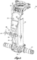
- FIGURE 2 A perspective view showing portions of a shock strut 150 with a torque link assembly 200 in accordance with the present invention is shown in FIGURE 2 .
- the torque link assembly 200 in this embodiment includes a lower torque link 202 having a first end 204 with a hinged connection to an axle assembly 152.
- the axle assembly 152 is attached to a piston 154 of a shock absorber.
- the torque link assembly 200 further includes an upper torque link 222 having a first end 224 with a hinged connection to a cylinder (not shown) of the shock absorber.
- a second end 206 of the lower torque link 202 is hingedly connected to a second end 226 of the upper torque link 222 with a locking quick release pin assembly 230, as described in more detail below.
- the upper torque link 222 and/or the lower torque link 202 may include one or more biasing members 205 that urge the torque links 202, 222 away from the piston 154.
- the torque links 202, 222 may be spring loaded such that the second ends 206, 226 are biased away from each other when the quick release pin assembly 230 is moved to a disengaged position, and remain apart until they are manually reengaged.
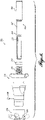
- FIGURE 3 is a front view of a portion of the torque link assembly 150 (with internal components indicated in phantom line), showing the quick release pin assembly 230 in the engaged position.
- the quick release pin assembly 230 includes a pin assembly 232 including a locking pin member 234 (shown in phantom) on one side of the quick release pin assembly 230 and a second pin assembly 232 including a locking pin member 234 on an opposite side of the quick release pin assembly 230.
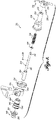
- FIGURE 4 which shows the pin assembly 232 in exploded view.
- the pin assembly 232 includes a handle 236, for example a T-handle that is connected to the locking pin member 234. Although a T-handle is shown in the currently preferred embodiment shown in the FIGURES, other handle shapes may be used and are contemplated by the present inventing, including knobs or the like.
- the locking pin member 234 has a rod portion 242 that is connected at one end to the handle 236, and a pin portion 244 that engages the upper and lower torque links 202, 222.
- the handle 236 is connected to the locking pin member 234 with a through connector 238 that extends through corresponding apertures 231, 241 in the handle 236 and rod portion 242 respectively.
- a guide pin 240 is fixed to, and extends outwardly from, the rod portion 242.
- a housing 250 comprising a housing body 252 and an end receiver 254, defines a center aperture 251 extending from the handle 236 and slidably receives the rod portion 242 of the locking pin member 234.
- An annular stop 258 slidably engages the rod portion 242 and abuts the pin portion 244 of the locking pin member 234.
- a biasing member 256 for example a coil spring, is disposed in the housing body 252 and abuts the annular stop 258. The biasing member 256 biases the locking pin member 234 inwardly toward an engaged position wherein the locking pin member 234 hingedly connects the lower and upper torque links, engaging corresponding apertures in both the lower torque link 202 and the upper torque link 222.
- the housing body 252 includes the center aperture 251 that is sized and configured to slidably receive the rod portion 242 of the locking pin member 234.
- the housing body 252 includes a guide channel having a longitudinal portion 253 and a circumferential portion 255.
- the longitudinal channel 253 extends along a portion of the the center aperture 251, and is sized and positioned to slidably receive the guide pin 240 extending from the rod portion 242.
- the longitudinal channel 253 intersects the circumferential channel 255, which is also sized and positioned to slidably receive the guide pin 240.
- the circumferential channel 255 in the present embodiment extends three hundred sixty degrees around the center aperture 251, in an alternative embodiment the circumferential channel extends only partially around the center aperture 251.
- the housing body 252 also defines an annular abutment 257 that is positioned to engage one end of the biasing member 256.
- a flanged end 259 of the housing body 252 is configured to be received into the annular end receiver 254 of the housing 250.
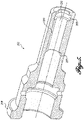
- FIGURE 6 showing a sectional view of the pin assembly 232 in the engaged position.
- the pin portion 244 of the locking pin member 234 slidably engages a bearing assembly comprising a first sleeve fitting 260 and a second sleeve fitting 265.
- the first sleeve fitting 260 has a tubular portion 262 that extends through an aperture 223 in the upper torque link 222, and a flange portion 264 that abuts the upper torque link 222.
- the second sleeve fitting 265 has a tubular portion 266 that extends through an aperture 203 in the lower torque link 202 and a flange portion 268 that abuts the flange portion 264 of the first sleeve fitting 260 and the lower torque link 202.
- the tubular portion 262 of the first sleeve fitting 260 slidably and closely engages the aperture 223 in the upper torque link 222 such that the flange portion 264 abuts the upper link 222, and the tubular portion 262 is configured to engage the housing body 252 in an interference fit.
- the housing body 252 may be heated prior to receiving or being pressed on to the tubular portion 262 such that upon cooling the housing body 252 is firmly secured to the first sleeve fitting 260.
- An end of the housing body 252 is received into the end receiver 254.
- the housing body 252 may threadably engage the tubular portion 262 of the first sleeve fitting 260.
- the locking pin member 234 of the assembly 232 is biased by the biasing member 256 towards the engaged position shown in FIGURE 6 , wherein the pin portion 244 engages both the lower torque link 202 and the upper torque link 222 through the first and second sleeve fittings 260, 265.
- the upper and lower links 202, 222 are thereby engaged to hinge about the pin portions 244.
- a user pulls the corresponding handle 236 outwardly away from the torque links (arrows 80) against the biasing force of the corresponding spring 256 to a disengaged position.
- the corresponding pin portion 244 of the locking pin member 234 exits the second sleeve fitting 265, disengaging from the lower torque link 202.
- the user turns the handle 236 (arrows 82) such that the guide pin 240 is offset from the longitudinal channel 253, retaining the locking pin member 234 in the disengaged position.
- one person can readily disengage the torque link assembly 230 by pulling one of the handles 236 outwardly to disengage one pin assembly 232 and rotating the handle 236 to retain the assembly 232 in the disengaged position, and simultaneously or sequentially disengaging the other pin assembly 232. If the torque links 202, 222 are biased to separate, for example with one or more biasing members 205 ( FIGURE 2 ), the torque links 202, 222 may move apart without further assistance. If needed, the user may manually separate the torque links 202, 222.
- the user To reassemble the torque links 202, 222 in the engaged position, the user aligns the torque links 202, 222 and may manually hold them in position while rotating the handle 236 for the pin assembly 232 on one side to align the guide pin 240 with the corresponding longitudinal channel 253.
- the biasing member 256 then urges the locking pin member 234 inwardly to insert the pin portion 244 into the second sleeve fitting 265.
- the opposite handle 236 may then be similarly rotated and moved to the engaged position.
- FIGURE 8 An alternative embodiment of a locking pin assembly 332 is illustrated in partially exploded view in FIGURE 8 . This embodiment is similar to the pin assembly 232 described above, except as discussed below. Aspects of the locking pin assembly 332 that are the same or similar to the pin assembly 232 shown in FIGURE 4 will not be repeated, for brevity and clarity.
- a guide pin 340 is fixed to, and extends inwardly into, the central aperture 351 of the housing body 352 (see, FIGURE 9 ).
- a locking pin member 334 having a rod portion 342 and a pin portion 344 is slidably received into the housing body 352.
- the pin portion 344 is configured to hingedly link the lower torque link 202 to the upper torque links 222, as discussed above.
- the rod portion 342 of the locking pin member 334 includes a guide channel comprising a longitudinal channel 353 and an intersecting circumferential channel 355.
- the guide pin 340 extending into the housing body 352 is positioned to slidably engage the longitudinal channel 353 when the locking pin assembly 332 is in the engaged position. While the guide pin 340 engages the longitudinal channel 353, the assembly including the handle 236 and locking pin member 334 is prevented from rotating about its axis.
- the circumferential channel 355 is sized and positioned to slidably receive the guide pin 340.
- the user pulls the handle 236 outwardly (as illustrated by arrows 80 in FIGURE 7 ) until the guide pin 340 enters and abuts the circumferential channel 355, and turns the handles 236 (as illustrated by arrows 82 in FIGURE 7 ) to lock the pin assemblies 332 in the disengaged position.
- the user aligns the torque links 202, 220 to align the corresponding pin apertures, and turns the handles 236 such that the guide pin 340 aligns with the longitudinal slot 353.
- the biasing member 256 is configured to urge the locking pin member 334 into the engaged position.
Landscapes
- Engineering & Computer Science (AREA)
- Mechanical Engineering (AREA)
- General Engineering & Computer Science (AREA)
- Aviation & Aerospace Engineering (AREA)
- Pivots And Pivotal Connections (AREA)
- Mutual Connection Of Rods And Tubes (AREA)
- Snaps, Bayonet Connections, Set Pins, And Snap Rings (AREA)
Claims (8)
- Verriegelungsstiftanordnung (232) für eine Drehmomentverbindungsanordnung (200) mit einer unteren Drehmomentverbindung (202), die ein erstes Ende (204) aufweist, das dazu ausgelegt ist, schwenkbar in ein Fahrwerk (100) einzugreifen, und ein zweites Ende (206), das einen ersten Verbindungsabschnitt aufweist, und einer oberen Drehmomentverbindung (222), die ein erstes Ende (224) aufweist, das dazu ausgelegt ist, schwenkbar in das Fahrwerk (100) einzugreifen, und ein zweites Ende (226), das einen zweiten Verbindungsabschnitt aufweist, wobei die Verriegelungsstiftanordnung (232) umfasst:ein Gehäuse (250), das dazu ausgelegt ist, an einer von der unteren Drehmomentverbindung (202) und der oberen Drehmomentverbindung (222) befestigt zu werden;ein Verriegelungsstiftorgan (234), das einen Stababschnitt (242) umfasst, der sich durch das Gehäuse (250) erstreckt, und einen Stiftabschnitt (244), der dazu ausgelegt ist, in eine Öffnung (203) im ersten Verbindungsabschnitt und durch eine Öffnung (223) im zweiten Verbindungsabschnitt eingesetzt zu werden, um die untere Drehmomentverbindung (202) mit der oberen Drehmomentverbindung (222) gelenkig zu verbinden; undein Vorspannelement (256), das dazu ausgelegt ist, das Verriegelungsstiftorgan (234) in Richtung zum zweiten Verbindungsabschnitt vorzuspannen,wobei das Verriegelungsstiftorgan (234) zwischen einer eingegriffenen Position, bei der der Stiftabschnitt (244) die untere Drehmomentverbindung (202) mit der oberen Drehmomentverbindung (222) gelenkig verbindet, und einer nicht eingegriffenen Position, bei der der Stiftabschnitt (244) die untere Drehmomentverbindung (202) nicht mit der oberen Drehmomentverbindung (222) verbindet, verschiebbar ist,dadurch gekennzeichnet, dass eines von dem Gehäuse (250) und dem Verriegelungsstiftorgan (234) weiter einen durchgehenden Kanal umfasst, der einen Längsabschnitt (253) und einen Umfangsabschnitt (255) umfasst, und das andere von dem Gehäuse (250) und dem Verriegelungsstiftorgan (234) weiter einen Führungsstift (240) umfasst, der derart in den Kanal eingreift, dass das Verriegelungsstiftorgan (234) zwischen der eingegriffenen Position und der nicht eingegriffenen Position bewegbar ist, wenn sich der Führungsstift (240) im Längsabschnitt (253) des Kanals befindet, und in der nicht eingegriffenen Position gehalten wird, wenn sich der Führungsstift (240) im Umfangsabschnitt (255) des Kanals befindet.
- Verriegelungsstiftanordnung (232) nach Anspruch 1, wobei das Verriegelungsstiftorgan (234) den Kanal umfasst und das Gehäuse (250) den Führungsstift (240) umfasst.
- Verriegelungsstiftanordnung (232) nach Anspruch 1, wobei das Gehäuse (250) den Kanal umfasst und das Verrieglungsstiftorgan (234) den Führungsstift (240) umfasst.
- Verriegelungsstiftanordnung (232) nach Anspruch 1, wobei das Gehäuse (250) einen Gehäusekörper (252) und eine Endaufnahme (254) umfasst, wobei der Gehäusekörper (252) verschiebbar in den Stababschnitt (242) des Verriegelungsstiftorgans (234) und den Endempfänger (254), der ein Ende des Gehäusekörpers (252) aufnimmt, eingreift.
- Verriegelungsstiftanordnung (232) nach Anspruch 1, wobei die Verriegelungsstiftanordnung (232) weiter einen Griff (236) umfasst, der mit einem distalen Ende des Stababschnitts (242) des Verriegelungsstiftorgans (234) verbunden ist.
- Verriegelungsstiftanordnung (232) nach Anspruch 5, wobei der Griff (236) ein T-förmiger Griff ist, der mit einem distalen Ende des Stababschnitts (242) des Verriegelungsstiftorgans (234) verbunden ist.
- Verriegelungsstiftanordnung (232) nach Anspruch 1, weiter umfassend eine erste Lagerhülse (265), die sich durch die Öffnung (203) im ersten Verbindungabschnitt erstreckt, und eine zweite Lagerhülse (260), die sich durch eine Öffnung (223) im zweiten Verbindungsabschnitt erstreckt, und wobei der Stiftabschnitt (244) des Verriegelungsstiftorgans (234) dazu ausgelegt ist, durch die erste und die zweite Lagerhülse (265, 260) eingesetzt zu werden.
- Drehmomentverbindungsanordnung (200), umfassend:eine untere Drehmomentverbindung (202), die ein erstes Ende (204) aufweist, das dazu ausgelegt ist, schwenkbar in ein Fahrwerk (100) einzugreifen, und ein zweites Ende (206), das einen ersten Verbindungsabschnitt aufweist;eine obere Drehmomentverbindung (222), die ein erstes Ende (224) aufweist, das dazu ausgelegt ist, schwenkbar in das Fahrwerk (100) einzugreifen, und ein zweites Ende (226), das einen zweiten Verbindungsabschnitt aufweist;erste und zweite Verriegelungsstiftanordnungen (232), wobei jede Verriegelungsstiftanordnung die Verbindungsstiftanordnung nach Anspruch 1 umfasst.
Applications Claiming Priority (1)
| Application Number | Priority Date | Filing Date | Title |
|---|---|---|---|
| US15/934,502 US11377206B2 (en) | 2018-03-23 | 2018-03-23 | Torque link apex quick release locking mechanism |
Publications (2)
| Publication Number | Publication Date |
|---|---|
| EP3543116A1 EP3543116A1 (de) | 2019-09-25 |
| EP3543116B1 true EP3543116B1 (de) | 2022-05-25 |
Family
ID=65904147
Family Applications (1)
| Application Number | Title | Priority Date | Filing Date |
|---|---|---|---|
| EP19164222.2A Active EP3543116B1 (de) | 2018-03-23 | 2019-03-21 | Schnell lösender verrieglungsmechanismus für den scheitelpunkt einer drehmomentverbindung |
Country Status (4)
| Country | Link |
|---|---|
| US (1) | US11377206B2 (de) |
| EP (1) | EP3543116B1 (de) |
| CN (1) | CN110294110B (de) |
| CA (1) | CA3036951A1 (de) |
Cited By (1)
| Publication number | Priority date | Publication date | Assignee | Title |
|---|---|---|---|---|
| RU2842110C1 (ru) * | 2024-12-06 | 2025-06-20 | Федеральное государственное казенное военное образовательное учреждение высшего образования "Военный учебно-научный центр Военно-воздушных сил "Военно-воздушная академия имени профессора Н.Е. Жуковского и Ю.А. Гагарина" (г. Воронеж) Министерства обороны Российской Федерации | Шлиц-шарнир опоры шасси самолета |
Families Citing this family (3)
| Publication number | Priority date | Publication date | Assignee | Title |
|---|---|---|---|---|
| GB2605160B (en) * | 2021-03-24 | 2023-05-31 | Safran Landing Systems Uk Ltd | Aircraft landing gear torque link assembly |
| CN113148118A (zh) * | 2021-05-10 | 2021-07-23 | 四川凌峰航空液压机械有限公司 | 任意锁定起落架需要位置的液压收放系统 |
| US12454979B2 (en) | 2022-09-23 | 2025-10-28 | Safran Landing Systems | Self-lubricating pin |
Family Cites Families (21)
| Publication number | Priority date | Publication date | Assignee | Title |
|---|---|---|---|---|
| GB356845A (en) | 1930-06-25 | 1931-09-17 | James William Punter | Improved means for preventing the displacement of engaged mechanical elements |
| US2279447A (en) | 1939-09-22 | 1942-04-14 | Cowey Leonard Eugene | Shock absorber strut or oleo leg for aircraft |
| US2499619A (en) | 1947-03-21 | 1950-03-07 | Menasco Mfg Company | Torque arm quick disconnect assembly |
| US2487329A (en) | 1947-03-21 | 1949-11-08 | Menasco Mfg Company | Torque arm quick disconnect assembly |
| US3397000A (en) * | 1964-12-27 | 1968-08-13 | Nakanishi Yoshitaka | One-touch plug-in lock |
| US3348869A (en) * | 1965-07-08 | 1967-10-24 | Warren B Zern | Slide fastener actuating devices |
| US4132376A (en) | 1977-09-12 | 1979-01-02 | Lockheed Corporation | Aircraft landing gear torque scissors with universal joint and quick disconnect |
| US4184783A (en) * | 1978-04-26 | 1980-01-22 | General Electric Company | Readily disengagable clevis |
| US4661009A (en) * | 1986-03-12 | 1987-04-28 | Grentek, Inc. | Quick change coupling for machine tool arbors and the like |
| US5807007A (en) | 1996-12-19 | 1998-09-15 | The United States Of America As Represented By The Administrator Of The National Aeronautics And Space Administration | Misalignment accommodating connector assembly |
| US6299223B1 (en) * | 1998-06-29 | 2001-10-09 | Southco, Inc. | Plunger latch |
| US6379076B1 (en) * | 2000-08-24 | 2002-04-30 | Tektronix, Inc. | Stackable, recessed, locking, insulated thumbscrew |
| DE102008048499B4 (de) * | 2008-09-23 | 2014-08-21 | Airbus Operations Gmbh | Snap and Click Staukasten-Haltesystem |
| US8667663B2 (en) * | 2008-12-05 | 2014-03-11 | Sikorsky Aircraft Corporation | Eccentric fitting assembly |
| FR2960215B1 (fr) * | 2010-05-18 | 2012-06-08 | Messier Dowty Sa | Dispositif de deverrouillage d'un atterrisseur dans une position deployee et atterrisseur equipe d'un tel dispositif |
| FR2961480B1 (fr) * | 2010-06-16 | 2012-08-10 | Messier Dowty Sa | Atterrisseur principal d'aeronef a deux balanciers articules sur la structure de l'aeronef. |
| JP5530298B2 (ja) * | 2010-08-06 | 2014-06-25 | 住友精密工業株式会社 | 降着装置 |
| MX341498B (es) * | 2010-10-18 | 2016-08-22 | Honda Patents & Tech North America Llc | Unidad de desenganche rápido para tren de aterrizaje de aeronave. |
| US8690180B1 (en) | 2013-03-08 | 2014-04-08 | HG Aircraft Products LLC | Towing adapter |
| FR3053311B1 (fr) * | 2016-07-01 | 2018-08-17 | Safran Landing Systems | Atterrisseur d’aeronef a actionneur de manœuvre rotatif |
| EP3287365B1 (de) * | 2016-08-25 | 2023-10-04 | Safran Landing Systems UK Ltd | Flugzeugfahrwerkstossdämpferanordnung |
-
2018
- 2018-03-23 US US15/934,502 patent/US11377206B2/en active Active
-
2019
- 2019-03-18 CA CA3036951A patent/CA3036951A1/en active Pending
- 2019-03-21 EP EP19164222.2A patent/EP3543116B1/de active Active
- 2019-03-25 CN CN201910229587.6A patent/CN110294110B/zh active Active
Cited By (1)
| Publication number | Priority date | Publication date | Assignee | Title |
|---|---|---|---|---|
| RU2842110C1 (ru) * | 2024-12-06 | 2025-06-20 | Федеральное государственное казенное военное образовательное учреждение высшего образования "Военный учебно-научный центр Военно-воздушных сил "Военно-воздушная академия имени профессора Н.Е. Жуковского и Ю.А. Гагарина" (г. Воронеж) Министерства обороны Российской Федерации | Шлиц-шарнир опоры шасси самолета |
Also Published As
| Publication number | Publication date |
|---|---|
| US11377206B2 (en) | 2022-07-05 |
| CN110294110B (zh) | 2024-08-30 |
| US20190291854A1 (en) | 2019-09-26 |
| CN110294110A (zh) | 2019-10-01 |
| EP3543116A1 (de) | 2019-09-25 |
| CA3036951A1 (en) | 2019-09-23 |
Similar Documents
| Publication | Publication Date | Title |
|---|---|---|
| EP2630036B1 (de) | Schnellkupplungsanordnung für ein flugzeug-fahrwerk | |
| EP3543116A1 (de) | Schnell lösender verrieglungsmechanismus für den scheitelpunkt einer drehmomentverbindung | |
| EP3437990B1 (de) | Zentraler verriegelungsmechanismus mit oberer drehmomentverbindung | |
| DE847235C (de) | Kupplungseinrichtung fuer Fluessigkeitsleitungen | |
| CN114269627B (zh) | 可转换手柄 | |
| WO2012027795A1 (en) | Folding stroller improvements | |
| DE102017205465A1 (de) | Radzusatzgewicht für ein landwirtschaftliches Nutzfahrzeug | |
| AU2013235771A1 (en) | Automatic lock system for vehicle hitch assembly | |
| US8925955B2 (en) | Hitch apparatus for vehicles | |
| US2863685A (en) | High-strength light-weight quick-disconnect coupling for a linkage system | |
| US5421599A (en) | Shock absorbing apparatus for tow couplers | |
| CA2749899C (en) | Fastening system for hanging mountable overhead containers | |
| US2487329A (en) | Torque arm quick disconnect assembly | |
| EP4335737A1 (de) | Anschlussvorrichtung zum kuppeln eines fahrradrahmens mit einem fahrradvorderteil, sowie ein set zum umwandeln eines fahrrads in ein lastenfahrrad | |
| US5887497A (en) | Release tool for telescoping towing arms | |
| US20120292885A1 (en) | Collapsible tow bar for light aircraft | |
| CN221394049U (zh) | 一种牵引装置 | |
| US20110101645A1 (en) | Teleswivel Hitch Apparatus | |
| US7464974B2 (en) | Quick-fold compact tow-bar | |
| TR2024012490Y (tr) | Hava aracı çekme aparatı. |
Legal Events
| Date | Code | Title | Description |
|---|---|---|---|
| PUAI | Public reference made under article 153(3) epc to a published international application that has entered the european phase |
Free format text: ORIGINAL CODE: 0009012 |
|
| STAA | Information on the status of an ep patent application or granted ep patent |
Free format text: STATUS: THE APPLICATION HAS BEEN PUBLISHED |
|
| AK | Designated contracting states |
Kind code of ref document: A1 Designated state(s): AL AT BE BG CH CY CZ DE DK EE ES FI FR GB GR HR HU IE IS IT LI LT LU LV MC MK MT NL NO PL PT RO RS SE SI SK SM TR |
|
| AX | Request for extension of the european patent |
Extension state: BA ME |
|
| STAA | Information on the status of an ep patent application or granted ep patent |
Free format text: STATUS: REQUEST FOR EXAMINATION WAS MADE |
|
| 17P | Request for examination filed |
Effective date: 20200323 |
|
| RBV | Designated contracting states (corrected) |
Designated state(s): AL AT BE BG CH CY CZ DE DK EE ES FI FR GB GR HR HU IE IS IT LI LT LU LV MC MK MT NL NO PL PT RO RS SE SI SK SM TR |
|
| RIC1 | Information provided on ipc code assigned before grant |
Ipc: F16C 11/04 20060101ALI20210924BHEP Ipc: F16B 21/12 20060101ALI20210924BHEP Ipc: B64C 25/50 20060101ALI20210924BHEP Ipc: F16C 11/02 20060101ALI20210924BHEP Ipc: B64C 25/60 20060101ALI20210924BHEP Ipc: F16B 21/00 20060101ALI20210924BHEP Ipc: B64C 25/00 20060101AFI20210924BHEP |
|
| GRAP | Despatch of communication of intention to grant a patent |
Free format text: ORIGINAL CODE: EPIDOSNIGR1 |
|
| STAA | Information on the status of an ep patent application or granted ep patent |
Free format text: STATUS: GRANT OF PATENT IS INTENDED |
|
| INTG | Intention to grant announced |
Effective date: 20211108 |
|
| GRAJ | Information related to disapproval of communication of intention to grant by the applicant or resumption of examination proceedings by the epo deleted |
Free format text: ORIGINAL CODE: EPIDOSDIGR1 |
|
| STAA | Information on the status of an ep patent application or granted ep patent |
Free format text: STATUS: REQUEST FOR EXAMINATION WAS MADE |
|
| INTC | Intention to grant announced (deleted) | ||
| GRAP | Despatch of communication of intention to grant a patent |
Free format text: ORIGINAL CODE: EPIDOSNIGR1 |
|
| STAA | Information on the status of an ep patent application or granted ep patent |
Free format text: STATUS: GRANT OF PATENT IS INTENDED |
|
| GRAS | Grant fee paid |
Free format text: ORIGINAL CODE: EPIDOSNIGR3 |
|
| GRAA | (expected) grant |
Free format text: ORIGINAL CODE: 0009210 |
|
| STAA | Information on the status of an ep patent application or granted ep patent |
Free format text: STATUS: THE PATENT HAS BEEN GRANTED |
|
| INTG | Intention to grant announced |
Effective date: 20220408 |
|
| AK | Designated contracting states |
Kind code of ref document: B1 Designated state(s): AL AT BE BG CH CY CZ DE DK EE ES FI FR GB GR HR HU IE IS IT LI LT LU LV MC MK MT NL NO PL PT RO RS SE SI SK SM TR |
|
| REG | Reference to a national code |
Ref country code: GB Ref legal event code: FG4D |
|
| REG | Reference to a national code |
Ref country code: CH Ref legal event code: EP |
|
| REG | Reference to a national code |
Ref country code: DE Ref legal event code: R096 Ref document number: 602019015172 Country of ref document: DE |
|
| REG | Reference to a national code |
Ref country code: AT Ref legal event code: REF Ref document number: 1494161 Country of ref document: AT Kind code of ref document: T Effective date: 20220615 |
|
| REG | Reference to a national code |
Ref country code: IE Ref legal event code: FG4D |
|
| REG | Reference to a national code |
Ref country code: LT Ref legal event code: MG9D |
|
| REG | Reference to a national code |
Ref country code: NL Ref legal event code: MP Effective date: 20220525 |
|
| REG | Reference to a national code |
Ref country code: AT Ref legal event code: MK05 Ref document number: 1494161 Country of ref document: AT Kind code of ref document: T Effective date: 20220525 |
|
| PG25 | Lapsed in a contracting state [announced via postgrant information from national office to epo] |
Ref country code: SE Free format text: LAPSE BECAUSE OF FAILURE TO SUBMIT A TRANSLATION OF THE DESCRIPTION OR TO PAY THE FEE WITHIN THE PRESCRIBED TIME-LIMIT Effective date: 20220525 Ref country code: PT Free format text: LAPSE BECAUSE OF FAILURE TO SUBMIT A TRANSLATION OF THE DESCRIPTION OR TO PAY THE FEE WITHIN THE PRESCRIBED TIME-LIMIT Effective date: 20220926 Ref country code: NO Free format text: LAPSE BECAUSE OF FAILURE TO SUBMIT A TRANSLATION OF THE DESCRIPTION OR TO PAY THE FEE WITHIN THE PRESCRIBED TIME-LIMIT Effective date: 20220825 Ref country code: NL Free format text: LAPSE BECAUSE OF FAILURE TO SUBMIT A TRANSLATION OF THE DESCRIPTION OR TO PAY THE FEE WITHIN THE PRESCRIBED TIME-LIMIT Effective date: 20220525 Ref country code: LT Free format text: LAPSE BECAUSE OF FAILURE TO SUBMIT A TRANSLATION OF THE DESCRIPTION OR TO PAY THE FEE WITHIN THE PRESCRIBED TIME-LIMIT Effective date: 20220525 Ref country code: HR Free format text: LAPSE BECAUSE OF FAILURE TO SUBMIT A TRANSLATION OF THE DESCRIPTION OR TO PAY THE FEE WITHIN THE PRESCRIBED TIME-LIMIT Effective date: 20220525 Ref country code: GR Free format text: LAPSE BECAUSE OF FAILURE TO SUBMIT A TRANSLATION OF THE DESCRIPTION OR TO PAY THE FEE WITHIN THE PRESCRIBED TIME-LIMIT Effective date: 20220826 Ref country code: FI Free format text: LAPSE BECAUSE OF FAILURE TO SUBMIT A TRANSLATION OF THE DESCRIPTION OR TO PAY THE FEE WITHIN THE PRESCRIBED TIME-LIMIT Effective date: 20220525 Ref country code: ES Free format text: LAPSE BECAUSE OF FAILURE TO SUBMIT A TRANSLATION OF THE DESCRIPTION OR TO PAY THE FEE WITHIN THE PRESCRIBED TIME-LIMIT Effective date: 20220525 Ref country code: BG Free format text: LAPSE BECAUSE OF FAILURE TO SUBMIT A TRANSLATION OF THE DESCRIPTION OR TO PAY THE FEE WITHIN THE PRESCRIBED TIME-LIMIT Effective date: 20220825 Ref country code: AT Free format text: LAPSE BECAUSE OF FAILURE TO SUBMIT A TRANSLATION OF THE DESCRIPTION OR TO PAY THE FEE WITHIN THE PRESCRIBED TIME-LIMIT Effective date: 20220525 |
|
| PG25 | Lapsed in a contracting state [announced via postgrant information from national office to epo] |
Ref country code: RS Free format text: LAPSE BECAUSE OF FAILURE TO SUBMIT A TRANSLATION OF THE DESCRIPTION OR TO PAY THE FEE WITHIN THE PRESCRIBED TIME-LIMIT Effective date: 20220525 Ref country code: PL Free format text: LAPSE BECAUSE OF FAILURE TO SUBMIT A TRANSLATION OF THE DESCRIPTION OR TO PAY THE FEE WITHIN THE PRESCRIBED TIME-LIMIT Effective date: 20220525 Ref country code: LV Free format text: LAPSE BECAUSE OF FAILURE TO SUBMIT A TRANSLATION OF THE DESCRIPTION OR TO PAY THE FEE WITHIN THE PRESCRIBED TIME-LIMIT Effective date: 20220525 Ref country code: IS Free format text: LAPSE BECAUSE OF FAILURE TO SUBMIT A TRANSLATION OF THE DESCRIPTION OR TO PAY THE FEE WITHIN THE PRESCRIBED TIME-LIMIT Effective date: 20220925 |
|
| PG25 | Lapsed in a contracting state [announced via postgrant information from national office to epo] |
Ref country code: SM Free format text: LAPSE BECAUSE OF FAILURE TO SUBMIT A TRANSLATION OF THE DESCRIPTION OR TO PAY THE FEE WITHIN THE PRESCRIBED TIME-LIMIT Effective date: 20220525 Ref country code: SK Free format text: LAPSE BECAUSE OF FAILURE TO SUBMIT A TRANSLATION OF THE DESCRIPTION OR TO PAY THE FEE WITHIN THE PRESCRIBED TIME-LIMIT Effective date: 20220525 Ref country code: RO Free format text: LAPSE BECAUSE OF FAILURE TO SUBMIT A TRANSLATION OF THE DESCRIPTION OR TO PAY THE FEE WITHIN THE PRESCRIBED TIME-LIMIT Effective date: 20220525 Ref country code: EE Free format text: LAPSE BECAUSE OF FAILURE TO SUBMIT A TRANSLATION OF THE DESCRIPTION OR TO PAY THE FEE WITHIN THE PRESCRIBED TIME-LIMIT Effective date: 20220525 Ref country code: DK Free format text: LAPSE BECAUSE OF FAILURE TO SUBMIT A TRANSLATION OF THE DESCRIPTION OR TO PAY THE FEE WITHIN THE PRESCRIBED TIME-LIMIT Effective date: 20220525 Ref country code: CZ Free format text: LAPSE BECAUSE OF FAILURE TO SUBMIT A TRANSLATION OF THE DESCRIPTION OR TO PAY THE FEE WITHIN THE PRESCRIBED TIME-LIMIT Effective date: 20220525 |
|
| REG | Reference to a national code |
Ref country code: DE Ref legal event code: R097 Ref document number: 602019015172 Country of ref document: DE |
|
| PG25 | Lapsed in a contracting state [announced via postgrant information from national office to epo] |
Ref country code: AL Free format text: LAPSE BECAUSE OF FAILURE TO SUBMIT A TRANSLATION OF THE DESCRIPTION OR TO PAY THE FEE WITHIN THE PRESCRIBED TIME-LIMIT Effective date: 20220525 |
|
| PLBE | No opposition filed within time limit |
Free format text: ORIGINAL CODE: 0009261 |
|
| STAA | Information on the status of an ep patent application or granted ep patent |
Free format text: STATUS: NO OPPOSITION FILED WITHIN TIME LIMIT |
|
| 26N | No opposition filed |
Effective date: 20230228 |
|
| PG25 | Lapsed in a contracting state [announced via postgrant information from national office to epo] |
Ref country code: SI Free format text: LAPSE BECAUSE OF FAILURE TO SUBMIT A TRANSLATION OF THE DESCRIPTION OR TO PAY THE FEE WITHIN THE PRESCRIBED TIME-LIMIT Effective date: 20220525 |
|
| PG25 | Lapsed in a contracting state [announced via postgrant information from national office to epo] |
Ref country code: MC Free format text: LAPSE BECAUSE OF FAILURE TO SUBMIT A TRANSLATION OF THE DESCRIPTION OR TO PAY THE FEE WITHIN THE PRESCRIBED TIME-LIMIT Effective date: 20220525 |
|
| REG | Reference to a national code |
Ref country code: CH Ref legal event code: PL |
|
| REG | Reference to a national code |
Ref country code: BE Ref legal event code: MM Effective date: 20230331 |
|
| PG25 | Lapsed in a contracting state [announced via postgrant information from national office to epo] |
Ref country code: LU Free format text: LAPSE BECAUSE OF NON-PAYMENT OF DUE FEES Effective date: 20230321 |
|
| REG | Reference to a national code |
Ref country code: IE Ref legal event code: MM4A |
|
| PG25 | Lapsed in a contracting state [announced via postgrant information from national office to epo] |
Ref country code: LI Free format text: LAPSE BECAUSE OF NON-PAYMENT OF DUE FEES Effective date: 20230331 Ref country code: IT Free format text: LAPSE BECAUSE OF FAILURE TO SUBMIT A TRANSLATION OF THE DESCRIPTION OR TO PAY THE FEE WITHIN THE PRESCRIBED TIME-LIMIT Effective date: 20220525 Ref country code: IE Free format text: LAPSE BECAUSE OF NON-PAYMENT OF DUE FEES Effective date: 20230321 Ref country code: CH Free format text: LAPSE BECAUSE OF NON-PAYMENT OF DUE FEES Effective date: 20230331 |
|
| PG25 | Lapsed in a contracting state [announced via postgrant information from national office to epo] |
Ref country code: BE Free format text: LAPSE BECAUSE OF NON-PAYMENT OF DUE FEES Effective date: 20230331 |
|
| PG25 | Lapsed in a contracting state [announced via postgrant information from national office to epo] |
Ref country code: BG Free format text: LAPSE BECAUSE OF FAILURE TO SUBMIT A TRANSLATION OF THE DESCRIPTION OR TO PAY THE FEE WITHIN THE PRESCRIBED TIME-LIMIT Effective date: 20220525 |
|
| PG25 | Lapsed in a contracting state [announced via postgrant information from national office to epo] |
Ref country code: BG Free format text: LAPSE BECAUSE OF FAILURE TO SUBMIT A TRANSLATION OF THE DESCRIPTION OR TO PAY THE FEE WITHIN THE PRESCRIBED TIME-LIMIT Effective date: 20220525 |
|
| PG25 | Lapsed in a contracting state [announced via postgrant information from national office to epo] |
Ref country code: CY Free format text: LAPSE BECAUSE OF FAILURE TO SUBMIT A TRANSLATION OF THE DESCRIPTION OR TO PAY THE FEE WITHIN THE PRESCRIBED TIME-LIMIT; INVALID AB INITIO Effective date: 20190321 |
|
| PG25 | Lapsed in a contracting state [announced via postgrant information from national office to epo] |
Ref country code: HU Free format text: LAPSE BECAUSE OF FAILURE TO SUBMIT A TRANSLATION OF THE DESCRIPTION OR TO PAY THE FEE WITHIN THE PRESCRIBED TIME-LIMIT; INVALID AB INITIO Effective date: 20190321 |
|
| PG25 | Lapsed in a contracting state [announced via postgrant information from national office to epo] |
Ref country code: TR Free format text: LAPSE BECAUSE OF FAILURE TO SUBMIT A TRANSLATION OF THE DESCRIPTION OR TO PAY THE FEE WITHIN THE PRESCRIBED TIME-LIMIT Effective date: 20220525 |
|
| PGFP | Annual fee paid to national office [announced via postgrant information from national office to epo] |
Ref country code: GB Payment date: 20260324 Year of fee payment: 8 |
|
| PGFP | Annual fee paid to national office [announced via postgrant information from national office to epo] |
Ref country code: DE Payment date: 20260320 Year of fee payment: 8 |
|
| PGFP | Annual fee paid to national office [announced via postgrant information from national office to epo] |
Ref country code: FR Payment date: 20260324 Year of fee payment: 8 |