EP3543089A1 - Device for reinforcing, sealing or damping a structural element - Google Patents
Device for reinforcing, sealing or damping a structural element Download PDFInfo
- Publication number
- EP3543089A1 EP3543089A1 EP18163716.6A EP18163716A EP3543089A1 EP 3543089 A1 EP3543089 A1 EP 3543089A1 EP 18163716 A EP18163716 A EP 18163716A EP 3543089 A1 EP3543089 A1 EP 3543089A1
- Authority
- EP
- European Patent Office
- Prior art keywords
- clip
- carrier
- structural element
- insertion element
- structural
- Prior art date
- Legal status (The legal status is an assumption and is not a legal conclusion. Google has not performed a legal analysis and makes no representation as to the accuracy of the status listed.)
- Granted
Links
- 238000007789 sealing Methods 0.000 title claims abstract description 10
- 230000003014 reinforcing effect Effects 0.000 title claims abstract description 7
- 238000013016 damping Methods 0.000 title 1
- 238000003780 insertion Methods 0.000 claims abstract description 80
- 230000037431 insertion Effects 0.000 claims abstract description 80
- 239000000853 adhesive Substances 0.000 claims abstract description 28
- 230000001070 adhesive effect Effects 0.000 claims abstract description 28
- 230000033001 locomotion Effects 0.000 claims abstract description 10
- 239000000463 material Substances 0.000 claims description 21
- 238000001746 injection moulding Methods 0.000 description 5
- 239000004952 Polyamide Substances 0.000 description 3
- 238000009413 insulation Methods 0.000 description 3
- 229920002647 polyamide Polymers 0.000 description 3
- 230000002787 reinforcement Effects 0.000 description 3
- 238000004873 anchoring Methods 0.000 description 2
- 239000011248 coating agent Substances 0.000 description 2
- 238000000576 coating method Methods 0.000 description 2
- 238000005260 corrosion Methods 0.000 description 2
- 230000007797 corrosion Effects 0.000 description 2
- 238000006073 displacement reaction Methods 0.000 description 2
- 239000013013 elastic material Substances 0.000 description 2
- 239000004033 plastic Substances 0.000 description 2
- 229920003023 plastic Polymers 0.000 description 2
- OMIHGPLIXGGMJB-UHFFFAOYSA-N 7-oxabicyclo[4.1.0]hepta-1,3,5-triene Chemical compound C1=CC=C2OC2=C1 OMIHGPLIXGGMJB-UHFFFAOYSA-N 0.000 description 1
- 229920000049 Carbon (fiber) Polymers 0.000 description 1
- 229920000571 Nylon 11 Polymers 0.000 description 1
- 229920000299 Nylon 12 Polymers 0.000 description 1
- 229920002292 Nylon 6 Polymers 0.000 description 1
- 229920002302 Nylon 6,6 Polymers 0.000 description 1
- 239000004917 carbon fiber Substances 0.000 description 1
- 238000010276 construction Methods 0.000 description 1
- 239000000356 contaminant Substances 0.000 description 1
- 239000000835 fiber Substances 0.000 description 1
- 239000003365 glass fiber Substances 0.000 description 1
- 238000007654 immersion Methods 0.000 description 1
- 238000002347 injection Methods 0.000 description 1
- 239000007924 injection Substances 0.000 description 1
- 230000001788 irregular Effects 0.000 description 1
- 239000000203 mixture Substances 0.000 description 1
- 229920002492 poly(sulfone) Polymers 0.000 description 1
- 229920000728 polyester Polymers 0.000 description 1
- 229920006393 polyether sulfone Polymers 0.000 description 1
- 229920000642 polymer Polymers 0.000 description 1
- 229920000098 polyolefin Polymers 0.000 description 1
- 229920002635 polyurethane Polymers 0.000 description 1
- 239000004814 polyurethane Substances 0.000 description 1
- 239000007787 solid Substances 0.000 description 1
- 239000000243 solution Substances 0.000 description 1
- XLYOFNOQVPJJNP-UHFFFAOYSA-N water Substances O XLYOFNOQVPJJNP-UHFFFAOYSA-N 0.000 description 1
- 238000003466 welding Methods 0.000 description 1
Images


Classifications
-
- B—PERFORMING OPERATIONS; TRANSPORTING
- B29—WORKING OF PLASTICS; WORKING OF SUBSTANCES IN A PLASTIC STATE IN GENERAL
- B29C—SHAPING OR JOINING OF PLASTICS; SHAPING OF MATERIAL IN A PLASTIC STATE, NOT OTHERWISE PROVIDED FOR; AFTER-TREATMENT OF THE SHAPED PRODUCTS, e.g. REPAIRING
- B29C44/00—Shaping by internal pressure generated in the material, e.g. swelling or foaming ; Producing porous or cellular expanded plastics articles
- B29C44/02—Shaping by internal pressure generated in the material, e.g. swelling or foaming ; Producing porous or cellular expanded plastics articles for articles of definite length, i.e. discrete articles
- B29C44/12—Incorporating or moulding on preformed parts, e.g. inserts or reinforcements
-
- B—PERFORMING OPERATIONS; TRANSPORTING
- B29—WORKING OF PLASTICS; WORKING OF SUBSTANCES IN A PLASTIC STATE IN GENERAL
- B29C—SHAPING OR JOINING OF PLASTICS; SHAPING OF MATERIAL IN A PLASTIC STATE, NOT OTHERWISE PROVIDED FOR; AFTER-TREATMENT OF THE SHAPED PRODUCTS, e.g. REPAIRING
- B29C65/00—Joining or sealing of preformed parts, e.g. welding of plastics materials; Apparatus therefor
- B29C65/48—Joining or sealing of preformed parts, e.g. welding of plastics materials; Apparatus therefor using adhesives, i.e. using supplementary joining material; solvent bonding
- B29C65/4865—Joining or sealing of preformed parts, e.g. welding of plastics materials; Apparatus therefor using adhesives, i.e. using supplementary joining material; solvent bonding containing additives
-
- B—PERFORMING OPERATIONS; TRANSPORTING
- B29—WORKING OF PLASTICS; WORKING OF SUBSTANCES IN A PLASTIC STATE IN GENERAL
- B29C—SHAPING OR JOINING OF PLASTICS; SHAPING OF MATERIAL IN A PLASTIC STATE, NOT OTHERWISE PROVIDED FOR; AFTER-TREATMENT OF THE SHAPED PRODUCTS, e.g. REPAIRING
- B29C65/00—Joining or sealing of preformed parts, e.g. welding of plastics materials; Apparatus therefor
- B29C65/48—Joining or sealing of preformed parts, e.g. welding of plastics materials; Apparatus therefor using adhesives, i.e. using supplementary joining material; solvent bonding
- B29C65/52—Joining or sealing of preformed parts, e.g. welding of plastics materials; Apparatus therefor using adhesives, i.e. using supplementary joining material; solvent bonding characterised by the way of applying the adhesive
- B29C65/54—Joining or sealing of preformed parts, e.g. welding of plastics materials; Apparatus therefor using adhesives, i.e. using supplementary joining material; solvent bonding characterised by the way of applying the adhesive between pre-assembled parts
- B29C65/542—Joining or sealing of preformed parts, e.g. welding of plastics materials; Apparatus therefor using adhesives, i.e. using supplementary joining material; solvent bonding characterised by the way of applying the adhesive between pre-assembled parts by injection
-
- B—PERFORMING OPERATIONS; TRANSPORTING
- B29—WORKING OF PLASTICS; WORKING OF SUBSTANCES IN A PLASTIC STATE IN GENERAL
- B29C—SHAPING OR JOINING OF PLASTICS; SHAPING OF MATERIAL IN A PLASTIC STATE, NOT OTHERWISE PROVIDED FOR; AFTER-TREATMENT OF THE SHAPED PRODUCTS, e.g. REPAIRING
- B29C66/00—General aspects of processes or apparatus for joining preformed parts
- B29C66/01—General aspects dealing with the joint area or with the area to be joined
- B29C66/05—Particular design of joint configurations
- B29C66/10—Particular design of joint configurations particular design of the joint cross-sections
- B29C66/11—Joint cross-sections comprising a single joint-segment, i.e. one of the parts to be joined comprising a single joint-segment in the joint cross-section
- B29C66/112—Single lapped joints
- B29C66/1122—Single lap to lap joints, i.e. overlap joints
-
- B—PERFORMING OPERATIONS; TRANSPORTING
- B29—WORKING OF PLASTICS; WORKING OF SUBSTANCES IN A PLASTIC STATE IN GENERAL
- B29C—SHAPING OR JOINING OF PLASTICS; SHAPING OF MATERIAL IN A PLASTIC STATE, NOT OTHERWISE PROVIDED FOR; AFTER-TREATMENT OF THE SHAPED PRODUCTS, e.g. REPAIRING
- B29C66/00—General aspects of processes or apparatus for joining preformed parts
- B29C66/01—General aspects dealing with the joint area or with the area to be joined
- B29C66/05—Particular design of joint configurations
- B29C66/10—Particular design of joint configurations particular design of the joint cross-sections
- B29C66/13—Single flanged joints; Fin-type joints; Single hem joints; Edge joints; Interpenetrating fingered joints; Other specific particular designs of joint cross-sections not provided for in groups B29C66/11 - B29C66/12
- B29C66/131—Single flanged joints, i.e. one of the parts to be joined being rigid and flanged in the joint area
- B29C66/1312—Single flange to flange joints, the parts to be joined being rigid
-
- B—PERFORMING OPERATIONS; TRANSPORTING
- B60—VEHICLES IN GENERAL
- B60R—VEHICLES, VEHICLE FITTINGS, OR VEHICLE PARTS, NOT OTHERWISE PROVIDED FOR
- B60R13/00—Elements for body-finishing, identifying, or decorating; Arrangements or adaptations for advertising purposes
- B60R13/08—Insulating elements, e.g. for sound insulation
- B60R13/0861—Insulating elements, e.g. for sound insulation for covering undersurfaces of vehicles, e.g. wheel houses
-
- B—PERFORMING OPERATIONS; TRANSPORTING
- B62—LAND VEHICLES FOR TRAVELLING OTHERWISE THAN ON RAILS
- B62D—MOTOR VEHICLES; TRAILERS
- B62D25/00—Superstructure or monocoque structure sub-units; Parts or details thereof not otherwise provided for
-
- B—PERFORMING OPERATIONS; TRANSPORTING
- B62—LAND VEHICLES FOR TRAVELLING OTHERWISE THAN ON RAILS
- B62D—MOTOR VEHICLES; TRAILERS
- B62D29/00—Superstructures, understructures, or sub-units thereof, characterised by the material thereof
- B62D29/001—Superstructures, understructures, or sub-units thereof, characterised by the material thereof characterised by combining metal and synthetic material
- B62D29/002—Superstructures, understructures, or sub-units thereof, characterised by the material thereof characterised by combining metal and synthetic material a foamable synthetic material or metal being added in situ
-
- C—CHEMISTRY; METALLURGY
- C09—DYES; PAINTS; POLISHES; NATURAL RESINS; ADHESIVES; COMPOSITIONS NOT OTHERWISE PROVIDED FOR; APPLICATIONS OF MATERIALS NOT OTHERWISE PROVIDED FOR
- C09K—MATERIALS FOR MISCELLANEOUS APPLICATIONS, NOT PROVIDED FOR ELSEWHERE
- C09K3/00—Materials not provided for elsewhere
- C09K3/10—Materials in mouldable or extrudable form for sealing or packing joints or covers
- C09K3/1006—Materials in mouldable or extrudable form for sealing or packing joints or covers characterised by the chemical nature of one of its constituents
- C09K3/1021—Polyurethanes or derivatives thereof
-
- F—MECHANICAL ENGINEERING; LIGHTING; HEATING; WEAPONS; BLASTING
- F16—ENGINEERING ELEMENTS AND UNITS; GENERAL MEASURES FOR PRODUCING AND MAINTAINING EFFECTIVE FUNCTIONING OF MACHINES OR INSTALLATIONS; THERMAL INSULATION IN GENERAL
- F16B—DEVICES FOR FASTENING OR SECURING CONSTRUCTIONAL ELEMENTS OR MACHINE PARTS TOGETHER, e.g. NAILS, BOLTS, CIRCLIPS, CLAMPS, CLIPS OR WEDGES; JOINTS OR JOINTING
- F16B19/00—Bolts without screw-thread; Pins, including deformable elements; Rivets
- F16B19/04—Rivets; Spigots or the like fastened by riveting
- F16B19/08—Hollow rivets; Multi-part rivets
- F16B19/10—Hollow rivets; Multi-part rivets fastened by expanding mechanically
- F16B19/1027—Multi-part rivets
- F16B19/1036—Blind rivets
- F16B19/1081—Blind rivets fastened by a drive-pin
-
- B—PERFORMING OPERATIONS; TRANSPORTING
- B29—WORKING OF PLASTICS; WORKING OF SUBSTANCES IN A PLASTIC STATE IN GENERAL
- B29C—SHAPING OR JOINING OF PLASTICS; SHAPING OF MATERIAL IN A PLASTIC STATE, NOT OTHERWISE PROVIDED FOR; AFTER-TREATMENT OF THE SHAPED PRODUCTS, e.g. REPAIRING
- B29C66/00—General aspects of processes or apparatus for joining preformed parts
- B29C66/70—General aspects of processes or apparatus for joining preformed parts characterised by the composition, physical properties or the structure of the material of the parts to be joined; Joining with non-plastics material
- B29C66/72—General aspects of processes or apparatus for joining preformed parts characterised by the composition, physical properties or the structure of the material of the parts to be joined; Joining with non-plastics material characterised by the structure of the material of the parts to be joined
- B29C66/727—General aspects of processes or apparatus for joining preformed parts characterised by the composition, physical properties or the structure of the material of the parts to be joined; Joining with non-plastics material characterised by the structure of the material of the parts to be joined being porous, e.g. foam
-
- B—PERFORMING OPERATIONS; TRANSPORTING
- B29—WORKING OF PLASTICS; WORKING OF SUBSTANCES IN A PLASTIC STATE IN GENERAL
- B29C—SHAPING OR JOINING OF PLASTICS; SHAPING OF MATERIAL IN A PLASTIC STATE, NOT OTHERWISE PROVIDED FOR; AFTER-TREATMENT OF THE SHAPED PRODUCTS, e.g. REPAIRING
- B29C66/00—General aspects of processes or apparatus for joining preformed parts
- B29C66/70—General aspects of processes or apparatus for joining preformed parts characterised by the composition, physical properties or the structure of the material of the parts to be joined; Joining with non-plastics material
- B29C66/74—Joining plastics material to non-plastics material
- B29C66/742—Joining plastics material to non-plastics material to metals or their alloys
-
- B—PERFORMING OPERATIONS; TRANSPORTING
- B29—WORKING OF PLASTICS; WORKING OF SUBSTANCES IN A PLASTIC STATE IN GENERAL
- B29K—INDEXING SCHEME ASSOCIATED WITH SUBCLASSES B29B, B29C OR B29D, RELATING TO MOULDING MATERIALS OR TO MATERIALS FOR MOULDS, REINFORCEMENTS, FILLERS OR PREFORMED PARTS, e.g. INSERTS
- B29K2063/00—Use of EP, i.e. epoxy resins or derivatives thereof, as moulding material
-
- B—PERFORMING OPERATIONS; TRANSPORTING
- B29—WORKING OF PLASTICS; WORKING OF SUBSTANCES IN A PLASTIC STATE IN GENERAL
- B29K—INDEXING SCHEME ASSOCIATED WITH SUBCLASSES B29B, B29C OR B29D, RELATING TO MOULDING MATERIALS OR TO MATERIALS FOR MOULDS, REINFORCEMENTS, FILLERS OR PREFORMED PARTS, e.g. INSERTS
- B29K2075/00—Use of PU, i.e. polyureas or polyurethanes or derivatives thereof, as moulding material
-
- B—PERFORMING OPERATIONS; TRANSPORTING
- B29—WORKING OF PLASTICS; WORKING OF SUBSTANCES IN A PLASTIC STATE IN GENERAL
- B29K—INDEXING SCHEME ASSOCIATED WITH SUBCLASSES B29B, B29C OR B29D, RELATING TO MOULDING MATERIALS OR TO MATERIALS FOR MOULDS, REINFORCEMENTS, FILLERS OR PREFORMED PARTS, e.g. INSERTS
- B29K2077/00—Use of PA, i.e. polyamides, e.g. polyesteramides or derivatives thereof, as moulding material
-
- B—PERFORMING OPERATIONS; TRANSPORTING
- B29—WORKING OF PLASTICS; WORKING OF SUBSTANCES IN A PLASTIC STATE IN GENERAL
- B29K—INDEXING SCHEME ASSOCIATED WITH SUBCLASSES B29B, B29C OR B29D, RELATING TO MOULDING MATERIALS OR TO MATERIALS FOR MOULDS, REINFORCEMENTS, FILLERS OR PREFORMED PARTS, e.g. INSERTS
- B29K2105/00—Condition, form or state of moulded material or of the material to be shaped
- B29K2105/04—Condition, form or state of moulded material or of the material to be shaped cellular or porous
- B29K2105/048—Expandable particles, beads or granules
-
- B—PERFORMING OPERATIONS; TRANSPORTING
- B29—WORKING OF PLASTICS; WORKING OF SUBSTANCES IN A PLASTIC STATE IN GENERAL
- B29K—INDEXING SCHEME ASSOCIATED WITH SUBCLASSES B29B, B29C OR B29D, RELATING TO MOULDING MATERIALS OR TO MATERIALS FOR MOULDS, REINFORCEMENTS, FILLERS OR PREFORMED PARTS, e.g. INSERTS
- B29K2305/00—Use of metals, their alloys or their compounds, as reinforcement
-
- B—PERFORMING OPERATIONS; TRANSPORTING
- B29—WORKING OF PLASTICS; WORKING OF SUBSTANCES IN A PLASTIC STATE IN GENERAL
- B29L—INDEXING SCHEME ASSOCIATED WITH SUBCLASS B29C, RELATING TO PARTICULAR ARTICLES
- B29L2031/00—Other particular articles
- B29L2031/30—Vehicles, e.g. ships or aircraft, or body parts thereof
-
- B—PERFORMING OPERATIONS; TRANSPORTING
- B60—VEHICLES IN GENERAL
- B60R—VEHICLES, VEHICLE FITTINGS, OR VEHICLE PARTS, NOT OTHERWISE PROVIDED FOR
- B60R13/00—Elements for body-finishing, identifying, or decorating; Arrangements or adaptations for advertising purposes
- B60R13/08—Insulating elements, e.g. for sound insulation
- B60R2013/0807—Arrangements of fasteners or clips specially adapted therefore
-
- F—MECHANICAL ENGINEERING; LIGHTING; HEATING; WEAPONS; BLASTING
- F16—ENGINEERING ELEMENTS AND UNITS; GENERAL MEASURES FOR PRODUCING AND MAINTAINING EFFECTIVE FUNCTIONING OF MACHINES OR INSTALLATIONS; THERMAL INSULATION IN GENERAL
- F16B—DEVICES FOR FASTENING OR SECURING CONSTRUCTIONAL ELEMENTS OR MACHINE PARTS TOGETHER, e.g. NAILS, BOLTS, CIRCLIPS, CLAMPS, CLIPS OR WEDGES; JOINTS OR JOINTING
- F16B11/00—Connecting constructional elements or machine parts by sticking or pressing them together, e.g. cold pressure welding
- F16B11/006—Connecting constructional elements or machine parts by sticking or pressing them together, e.g. cold pressure welding by gluing
-
- F—MECHANICAL ENGINEERING; LIGHTING; HEATING; WEAPONS; BLASTING
- F16—ENGINEERING ELEMENTS AND UNITS; GENERAL MEASURES FOR PRODUCING AND MAINTAINING EFFECTIVE FUNCTIONING OF MACHINES OR INSTALLATIONS; THERMAL INSULATION IN GENERAL
- F16B—DEVICES FOR FASTENING OR SECURING CONSTRUCTIONAL ELEMENTS OR MACHINE PARTS TOGETHER, e.g. NAILS, BOLTS, CIRCLIPS, CLAMPS, CLIPS OR WEDGES; JOINTS OR JOINTING
- F16B5/00—Joining sheets or plates, e.g. panels, to one another or to strips or bars parallel to them
- F16B5/06—Joining sheets or plates, e.g. panels, to one another or to strips or bars parallel to them by means of clamps or clips
- F16B5/0607—Joining sheets or plates, e.g. panels, to one another or to strips or bars parallel to them by means of clamps or clips joining sheets or plates to each other
- F16B5/0621—Joining sheets or plates, e.g. panels, to one another or to strips or bars parallel to them by means of clamps or clips joining sheets or plates to each other in parallel relationship
- F16B5/0664—Joining sheets or plates, e.g. panels, to one another or to strips or bars parallel to them by means of clamps or clips joining sheets or plates to each other in parallel relationship at least one of the sheets or plates having integrally formed or integrally connected snap-in-features
Definitions
- the invention relates to a device for reinforcement, sealing or insulation of a structural element with a carrier and an adhesive. It further relates to a system having a structural element and a device arranged therein for reinforcement, sealing or insulation of the structural element.
- components such as bodies and / or frames of transport and locomotion, especially of vehicles by water or land or aircraft, have structures with cavities to allow lightweight constructions.
- cavities cause a variety of problems.
- it must be sealed to prevent the ingress of moisture and contaminants which can lead to corrosion of the components.
- it is also desirable to substantially strengthen the cavities and thus the device, but to maintain the low weight.
- it is also necessary to stabilize the cavities and thus the components to reduce noise that would otherwise be transmitted through or through the cavity.
- Many of these voids are irregular in shape or narrow in size, making it difficult to properly seal, reinforce, and insulate them.
- sealing elements (English: baffle) are used to seal cavities and / or acoustically isolate, or reinforcing elements (English: reinforcer) used to reinforce cavities.
- a body of an automobile is shown schematically.
- the body 10 in this case has various structures with cavities, such as columns 14 and beams or struts 12.
- Such structural elements 12, 14 with cavities are usually sealed or reinforced with sealing and / or reinforcing elements 16.
- Fig. 2a and 2b schematically show a known concept for sealing and / or reinforcing closure of openings or cavities in a motor vehicle. It shows the Fig. 2a a device 16 prior to expansion of an expandable material 13. Fig. 2b shows the same device 16 as part of the system 1, but after an expansion of the expandable material 13, ie with the expanded material 13 '.
- the device 16 is located in a cavity of a body structure, as for example in Fig. 1 is shown. A portion of such a structural element 12, 14 of a body is in the Fig. 2a and 2b shown schematically.
- the device 16 comprises a carrier 11, which has an edge region 21.
- the expandable material 13 is arranged substantially on this edge region 21 of the carrier 11.
- the expandable material 13 Prior to expansion of the expandable material 13, there is a gap between the device 16 and the structural member 12, 14. This gap makes it possible to coat the structural element 12, 14 in order to achieve corrosion protection of the structural element 12, 14. After this coating, the expandable material 13 is usually expanded by a heat action, whereby the expanded material 13 'thereby closes the gap between the device 16 and the structural element 12, 14. In addition, a fixation of the device 16 'in the structural element 12, 14 is achieved by the expansion of the expandable material 13 at the same time. A device 16 'fastened in the structural element 12, 14 on the one hand reinforces the structural element 12, 14 and on the other hand closes the cavity in the structural element 12, 14.
- Devices 16 shown are usually prefixed by clips on the structural elements 12, 14. This pre-fixing serves to hold the device 16 at the desired location in the body 10 before the carrier 11 of the device 16 is finally secured with adhesive 13 in the structural member 12, 14.
- Such pre-fixing by means of clips also makes it possible to coat the structural element 12, 14 with an immersion coating, without the prefixed device 16 being washed away.
- a typical embodiment of such prefixing is shown.
- 16 clips 5 are used for pre-fixing the device, which can be hooked into corresponding openings in the structural elements 12, 14.
- FIG. 3a Such a clip 5 is shown schematically in a spatial representation.
- the clip 5 has a base 7, and two arranged on this base 7 elastic wings 6.1, 6.2. These wings 6.1, 6.2 have hook-shaped elements which are intended to latch on the corresponding edges of the openings in the structural elements 12, 14.
- Fig. 3b a section of a prefixed device 16 on a structural element 12, 14 is shown.
- the device 16 is shown from below.
- the wings 6.1, 6.2 are hooked to the corresponding edges of the structural element 12, 14.
- the invention is therefore based on the object, an improved device for reinforcement, sealing or insulation of a structural element available provide, which does not have the disadvantages mentioned above.
- the device should be improved in terms of prefixing in the structural element, so that it can be ensured that the device is prefixed to the desired position in the structural element until an adhesive finally connects the carrier with the structural element.
- a device for reinforcing, sealing or insulating a structural element in a motor vehicle comprising: a carrier with a clip for prefixing the device in the structural element, the clip comprising a base and two elastic wings arranged on the base; an adhesive for bonding the carrier in the structural element; and a male member which is insertable into a space between the base and the wings of the clip in such a way when the device is pre-fixed by the clip on the structural member, that the elastic wings are limited in their range of motion.
- This solution has the advantage that can be significantly stabilized and improved by a simple, inexpensive element, namely the insertion element, a pre-fixing in a simple and cost-effective manner.
- a simple, inexpensive element namely the insertion element
- a pre-fixing in a simple and cost-effective manner.
- a core idea of the present invention is that by restricting a movement clearance of the elastic wings of the clip, twisting, displacement or release of the clip on the structural element can be effectively prevented. It is particularly advantageous that no further adjustments to existing systems must be made. It is sufficient to provide a simple and cost-effective additional element, namely the insertion element, in order to substantially improve the prefixing of the device in the structural element.
- the insertion element is connected by a flexible web to the carrier.
- the insertion element is arranged by the flexible web in an area of the clip on the carrier.
- Such an arrangement offers the advantage that the insertion element is present at the intended location, namely in the vicinity of the clip. Thus, handling of the entire system is simplified.
- the insertion element and the carrier are integrally formed.
- the male member and the carrier are formed of the same material.
- the flexible web is longer than a height of the male member.
- the male member and the carrier are formed as separate elements.
- the carrier and the insertion element are not formed of the same material.
- Such a separate arrangement of the insertion element and the carrier has the advantage that on the one hand a simple injection mold for producing these parts can be used, and that on the other different materials can be used, which can be optimized with respect to a function of the respective elements.
- the carrier and the clip formed thereon can be formed of a more elastic material, and the insertion element can be made of a less elastic material.
- the carrier has a pocket-shaped depression in a region of the clip, the insertion element having a base which engages in this pocket-shaped depression when the insertion element is introduced into the clip.
- the base is designed such that it essentially fills the depression when the insertion element is introduced into the clip.
- the insertion element can be connected by positive engagement with the carrier and / or the structural element.
- the insertion element has one or more hooks, which can be latched to the carrier and / or the structural element.
- Such a connection between the insertion element and the carrier or structural element by positive locking offers the advantage that in this way a secure mechanical connection is created, which protects the insertion element against falling out.
- this has the advantage that the user can determine during a manipulation, for example by a clicking sound, whether the insertion element is inserted in the intended position in the clip or not.
- the insertion element can be connected by adhesion to the carrier and / or the structural element.
- the insertion element and the clip are designed so that they engage in a wedge-like manner when the insertion element is introduced into the clip.
- Such a connection between the insertion element and the carrier or structural element by means of frictional connection has the advantage that the corresponding elements can be manufactured with greater tolerances than is the case with positive locking. As a result, more cost-effective insertion elements can be used in particular.
- the insertion element has connecting elements, which are operatively connected to the structural element and / or with the carrier when the insertion element is inserted in the clip.
- the insertion element has connecting elements, which are only operatively connected to the structural element when the insertion element is introduced in the clip.
- the connecting elements may be formed, for example, as hooks or wedge-shaped sections.
- Such an operative connection between the insertion element and the structural element has the advantage that not only the carrier but also the insertion element is prefixed directly to the structural element. Thus, a better protection against falling of the device can be achieved by the structural element.
- the insertion element has connecting elements, which are only operatively connected to the carrier when the insertion element is inserted in the clip.
- the connecting elements may be configured, for example, as hooks, wedge-shaped element sections or other types of elements.
- Such an operative connection between the insertion element and the carrier has the advantage that the insertion element can thereby be formed independently of the configuration of the structural element. This means that, for example, a single insertion element can be used for different thickness structural elements.
- the carrier has only one clip for prefixing the device in the structural element.
- the adhesive is disposed on the carrier.
- carrier and adhesive are pre-fixed together by the clip on the structural element.
- the adhesive is arranged on the carrier by an injection molding process.
- a two component injection molding process can be used to make the backing and adhesive.
- the backing is prefixed to the structural member without adhesive, and the adhesive is separately introduced into the structural member.
- the adhesive is applied to the structural element or to the carrier.
- the adhesive can be extruded onto the carrier or the structural element.
- the adhesive is formed as a non-expandable adhesive.
- non-expandable refers to an adhesive which, when cured, enlarges or reduces by at most 5% of its original volume.
- the adhesive is formed as an expandable adhesive.
- the expandable adhesive forms a single continuous element. In an alternative embodiment, several non-contiguous expandable adhesives form multiple non-contiguous elements.
- the expandable adhesive has an expansion rate of 300 to 3000%. In an exemplary embodiment, the expandable adhesive has an expansion rate of 1000 and 2700% and between 1500 and 2500%.
- An exemplary material with such an expansion rate is available under the trade name SikaBaffle® 450.
- the expandable adhesive has an expansion rate of 50 to 500%. In an exemplary embodiment, the expandable adhesive has an expansion rate of 70 and 400% and between 100 and 300%.
- An exemplary material having such an expansion rate is available under the trade name SikaReinforcer® 911.
- the carrier can be made of different materials.
- Preferred materials are plastics, in particular polyurethanes, polyamides, polyesters and polyolefins, preferably high-temperature resistant polymers such as poly (phenylene ether), polysulfones or polyethersulfones.
- Particular preference is given to using polyamide, in particular polyamide 6, polyamide 6,6, polyamide 11, polyamide 12 or a mixture thereof.
- fibers such as glass fibers or carbon fibers, are possible.
- the carrier may have any structure and any structure. It may, for example, be solid, hollow, or foamed or have a lattice-like structure.
- the surface of the carrier may typically be smooth, rough or textured.
- the carrier is made by an injection molding process.
- the carrier comprises a plastic, in particular polyamide.
- a system of a reinforced, sealed or insulated structural element in a motor vehicle comprising: a structural element; and a device according to the above Description, wherein the device is fixed by the clip to the structural member, and wherein the insertion element is at least partially disposed in the space between the base and the wings of the clip, so that the elastic wings are limited in their range of motion.
- the adhesive is formed as an expandable material.
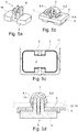
- a first variant of an exemplary prefixing of a device is shown in a structural element. It shows the Fig. 4a an exemplary insertion element 3 in a spatial representation.
- the Fig. 4b shows the exemplary insertion element 3, as it is arranged in the clip 5 of the carrier 11, also in a spatial representation.
- the Fig. 4c shows a bottom view of the prefix according to Fig. 4b.
- Fig. 4d shows a cross section of the schematic prefixing along the cutting plane AA in Fig. 4b
- the Fig. 4e shows a cross section along a sectional plane BB in the prefix according to Fig. 4b ,
- the insertion element 3 according Fig. 4a has four arm-like extensions, which each form a hook 4 at one end.
- the arm-like extensions are designed as wedge-shaped elements 18.
- the four extensions are connected to each other via a common base.
- Fig. 4b is the insertion element 3 off Fig. 4a inserted in a clip 5. It can be seen that the arms of the insertion element 3 fill the intermediate region between the base 7 and the elastic wings 6.1, 6.2 of the clip 5 such that a range of motion of these elastic wings 6.1, 6.2 is limited.
- the hooks 4 of the insertion element 3 are provided to enter into a state of use a positive connection with the structural element 12, 14. This is from the cross section according to Fig. 4e along the section line BB visible.
- Fig. 4c is the spatial representation according to Fig. 4b shown in a view from below.
- Fig. 4d is a cross section along the line AA from the Fig. 4b shown. It can be seen how the arm-like extensions of the insertion element 3 with its wedge-shaped elements 18 a range of motion of the elastic wings 6.1, 6.2 Restrict the clip 5 by the extensions of the insertion element 3 intermediate areas between the base 7 and the elastic wings 6.1, 6.2 of the clip 5 fill.
- a second variant of a prefixing of the device to a structural element is shown by way of example and schematically. It shows the Fig. 5a a second variant of a male element 3, the Fig. 5b shows such an insertion element 3 inserted in a clip 5, the Fig. 5c shows a bottom view of the prefix according to Fig. 5b , and the Fig. 5d shows a cross section of the prefix according to Fig. 5b along the cutting plane AA.
- the insertion element 3 in this embodiment in turn has four arm-like extensions which each form a hook 4 at one end, and which in turn form a wedge-shaped section 18.
- This socket 2 is dimensioned such that it engages in a corresponding pocket-like recess 9 of the carrier 11 when the insertion element 3 is inserted in the clip 5.
- FIG. 6a and 6b two different variants of the anchoring of the insertion element 3 are shown.
- Fig. 6a the insertion element 3 is anchored directly to the structural element 12, 14.
- the hooks 4 engage at the corresponding edges of the structural element 12, 14 when the insertion element 3 is fully inserted into the clip 5.
- Fig. 6b In contrast, the insertion element 3 is anchored to the carrier 11.
- the hooks 4 are arranged on the insertion element 3 deeper on the arm-like extensions, so that these engage at the provided edges of the carrier 11 when the insertion element 3 is fully inserted into the clip 5.
- Fig. 7 a section of an exemplary device is shown, wherein the insertion element 3 is connected via a web 8 with the carrier 11.
- the elastic web 8 is arranged in a region of the clip 5 on the carrier 11.
- an adhesive 13 is disposed on the carrier 11.
Abstract
Eine Vorrichtung (16) zur Verstärkung, Abdichtung oder Dämmung eines Strukturelementes (12, 14) in einem Kraftfahrzeug umfasst einen Träger (11) mit einem Clip (5) zur Vorfixierung der Vorrichtung im Strukturelement. Der Clip umfasst eine Basis (7) und zwei an der Basis angeordnete elastische Flügel (6.1, 6,2). Die Vorrichtung umfasst weiterhin einen Klebstoff (13) zur Verklebung des Trägers im Strukturelement. Weiterhin umfasst die Vorrichtung ein Einschubelement (3), welches in einen Zwischenraum zwischen der Basis (7) und den Flügeln (6.1, 6,2) des Clips derart einschiebbar ist, wenn die Vorrichtung durch den Clip am Strukturelement vorfixiert ist, dass die elastischen Flügel (6.1, 6,2) in ihrem Bewegungsspielraum eingeschränkt sind.A device (16) for reinforcing, sealing or insulating a structural element (12, 14) in a motor vehicle comprises a carrier (11) with a clip (5) for prefixing the device in the structural element. The clip comprises a base (7) and two elastic wings (6.1, 6.2) arranged at the base. The device further comprises an adhesive (13) for bonding the carrier in the structural element. Furthermore, the device comprises an insertion element (3), which in such a way inserted in a space between the base (7) and the wings (6.1, 6.2) of the clip, when the device is prefixed by the clip on the structural element that the elastic Wings (6.1, 6.2) are limited in their range of motion.
Description
Die Erfindung betrifft eine Vorrichtung zur Verstärkung, Abdichtung oder Dämmung eines Strukturelementes mit einem Träger und einem Klebstoff. Sie betrifft des Weiteren ein System mit einem Strukturelement und einer darin angeordneten Vorrichtung zur Verstärkung, Abdichtung oder Dämmung des Strukturelementes.The invention relates to a device for reinforcement, sealing or insulation of a structural element with a carrier and an adhesive. It further relates to a system having a structural element and a device arranged therein for reinforcement, sealing or insulation of the structural element.
Vielfach weisen Bauelemente, wie beispielsweise Karosserien und/oder Rahmen von Transport- und Fortbewegungsmitteln, insbesondere von Fahrzeugen zu Wasser oder zu Land oder von Luftfahrzeugen, Strukturen mit Hohlräumen auf, um leichtgewichtige Konstruktionen zu ermöglichen. Diese Hohlräume verursachen jedoch verschiedenste Probleme. Je nach Art des Hohlraumes muss dieser zum Verhindern des Eindringens von Feuchtigkeit und Verschmutzungen, die zur Korrosion der Bauelemente führen können, abgedichtet werden. Oft ist es auch wünschenswert, die Hohlräume und somit das Bauelement wesentlich zu verstärken, jedoch das geringe Gewicht beizubehalten. Oft ist es auch notwendig, die Hohlräume und somit die Bauelemente zu stabilisieren, um Geräusche, die sonst den Hohlraum entlang oder durch diesen hindurch übertragen werden würden, zu reduzieren. Viele dieser Hohlräume weisen eine unregelmässige Form oder ein enges Ausmass auf, wodurch es erschwert wird, sie richtig abzudichten, zu verstärken und zu dämmen.In many cases, components, such as bodies and / or frames of transport and locomotion, especially of vehicles by water or land or aircraft, have structures with cavities to allow lightweight constructions. However, these cavities cause a variety of problems. Depending on the nature of the cavity, it must be sealed to prevent the ingress of moisture and contaminants which can lead to corrosion of the components. Often it is also desirable to substantially strengthen the cavities and thus the device, but to maintain the low weight. Often, it is also necessary to stabilize the cavities and thus the components to reduce noise that would otherwise be transmitted through or through the cavity. Many of these voids are irregular in shape or narrow in size, making it difficult to properly seal, reinforce, and insulate them.
Insbesondere im Automobilbau, aber auch im Flugzeug- und Bootsbau, werden deshalb Abdichtungselemente (Englisch: baffle) verwendet, um Hohlräume abzudichten und/ oder akustisch abzuschotten, oder Verstärkungselemente (Englisch: reinforcer) verwendet, um Hohlräume zu verstärken.In particular, in the automotive industry, but also in aircraft and boat building, therefore, sealing elements (English: baffle) are used to seal cavities and / or acoustically isolate, or reinforcing elements (English: reinforcer) used to reinforce cavities.
In
Die Vorrichtung 16 befindet sich in einem Hohlraum einer Karosseriestruktur, wie sie beispielsweise in
Vor der Expansion des expandierbaren Materials 13 besteht zwischen der Vorrichtung 16 und dem Strukturelement 12, 14 ein Spalt. Dieser Spalt erlaubt es, das Strukturelement 12, 14 zu beschichten, um einen Korrosionsschutz des Strukturelementes 12, 14 zu erreichen. Nach dieser Beschichtung wird das expandierbare Material 13 üblicherweise durch eine Wärmeeinwirkung expandiert, wobei das expandierte Material 13' dadurch den Spalt zwischen der Vorrichtung 16 und dem Strukturelement 12, 14 schliesst. Zudem wird durch die Expansion des expandierbaren Materials 13 auch zugleich eine Fixierung der Vorrichtung 16' im Strukturelement 12, 14 erreicht. Eine derart im Strukturelement 12, 14 befestigte Vorrichtung 16' verstärkt einerseits das Strukturelement 12, 14 und verschliesst andererseits den Hohlraum im Strukturelement 12, 14.Prior to expansion of the
Solche in den
In den
In
In
Bei gewissen Vorrichtungen 16 sind solche Clips 5 zur Vorfixierung jedoch problematisch, insbesondere dann, wenn während der Vorfixierung der Vorrichtung 16 im Strukturelement 12, 14 eine grössere Kraft auf den Clip 5 einwirkt. Beispielsweise gibt es Situationen, in welchen die Vorfixierung des Clips 5 am Strukturelement 12, 14 einer Rotationskraft ausgesetzt ist. Sie tritt vor allem dann auf, wenn die Vorrichtung 16 mit lediglich einem Clip am Strukturelement 12, 14 vorfixiert wird, und wenn die Vorrichtung tendenziell gross und schwer ausgebildet ist. Dies kann dazu führen, dass die Vorrichtung 16 nicht an der gewünschten Position gehalten bzw. vorfixiert werden kann und im Extremfall kann es zu einem Lösen der Vorfixierung zwischen Vorrichtung 16 und Strukturelement 12, 14 kommen. In
Der Erfindung liegt daher die Aufgabe zugrunde, eine verbesserte Vorrichtung zur Verstärkung, Abdichtung oder Dämmung eines Strukturelementes zur Verfügung zu stellen, welche die oben genannten Nachteile nicht aufweist. Insbesondere soll die Vorrichtung hinsichtlich der Vorfixierung im Strukturelement verbessert werden, so dass sichergestellt werden kann, dass die Vorrichtung an der gewünschten Position im Strukturelement vorfixiert ist, bis ein Klebstoff den Träger endgültig mit dem Strukturelement verbindet.The invention is therefore based on the object, an improved device for reinforcement, sealing or insulation of a structural element available provide, which does not have the disadvantages mentioned above. In particular, the device should be improved in terms of prefixing in the structural element, so that it can be ensured that the device is prefixed to the desired position in the structural element until an adhesive finally connects the carrier with the structural element.
Diese Aufgabe wird gelöst durch eine Vorrichtung zur Verstärkung, Abdichtung oder Dämmung eines Strukturelementes in einem Kraftfahrzeug, umfassend: einen Träger mit einem Clip zur Vorfixierung der Vorrichtung im Strukturelement, wobei der Clip eine Basis und zwei an der Basis angeordnete, elastische Flügel umfasst; einen Klebstoff zur Verklebung des Trägers im Strukturelement; und ein Einschubelement, welches in einen Zwischenraum zwischen der Basis und den Flügeln des Clips derart einschiebbar ist, wenn die Vorrichtung durch den Clip am Strukturelement vorfixiert ist, dass die elastischen Flügel in ihrem Bewegungsspielraum eingeschränkt sind.This object is achieved by a device for reinforcing, sealing or insulating a structural element in a motor vehicle, comprising: a carrier with a clip for prefixing the device in the structural element, the clip comprising a base and two elastic wings arranged on the base; an adhesive for bonding the carrier in the structural element; and a male member which is insertable into a space between the base and the wings of the clip in such a way when the device is pre-fixed by the clip on the structural member, that the elastic wings are limited in their range of motion.
Diese Lösung hat den Vorteil, dass durch ein einfaches, kostengünstiges Element, nämlich das Einschubelement, eine Vorfixierung auf einfache und kostengünstige Art und Weise wesentlich stabilisiert und verbessert werden kann. Durch das Vorsehen eines solchen Einschubelementes wird es möglich, auf Vorrichtungen, welche lediglich über einen Clip mit dem Strukturelement vorfixiert werden müssen, zuverlässig im Strukturelement zu fixieren. Somit ist es nicht in jedem Fall zwingend, Vorfixierungselemente, wie beispielsweise weitere Clips oder Schweisslaschen oder Ähnliches, an den Vorrichtungen vorzusehen.This solution has the advantage that can be significantly stabilized and improved by a simple, inexpensive element, namely the insertion element, a pre-fixing in a simple and cost-effective manner. By providing such a push-in element, it becomes possible to reliably fix in the structural element on devices which only have to be prefixed to the structural element via a clip. Thus, it is not always necessary to provide pre-fixing elements, such as other clips or welding tabs or the like, on the devices.
Ein Kerngedanke der vorliegenden Erfindung ist es, dass durch eine Einschränkung eines Bewegungsspielraumes der elastischen Flügel des Clips ein Verdrehen, Verschieben bzw. Lösen des Clips am Strukturelement wirksam verhindert werden kann. Dabei ist insbesondere vorteilhaft, dass keine weiteren Anpassungen an bestehenden Systemen vorgenommen werden müssen. Es reicht aus, ein einfaches und kostengünstiges zusätzliches Element, nämlich das Einschubelement, vorzusehen, um die Vorfixierung der Vorrichtung im Strukturelement wesentlich zu verbessern.A core idea of the present invention is that by restricting a movement clearance of the elastic wings of the clip, twisting, displacement or release of the clip on the structural element can be effectively prevented. It is particularly advantageous that no further adjustments to existing systems must be made. It is sufficient to provide a simple and cost-effective additional element, namely the insertion element, in order to substantially improve the prefixing of the device in the structural element.
In einer beispielhaften Ausführungsform ist das Einschubelement durch einen flexiblen Steg mit dem Träger verbunden.In an exemplary embodiment, the insertion element is connected by a flexible web to the carrier.
Dies hat den Vorteil, dass dadurch der Träger und das Einschubelement jeweils beisammen sind. Somit wird eine Logistik bzw. Handhabung des gesamten Systems vereinfacht, und Fehlmanipulationen (beispielsweise eine Verwendung von nicht zusammenpassenden Einschubelementen und Trägern) werden wirksam verhindert.This has the advantage that thereby the carrier and the insertion element are each together. Thus, logistics of the whole system is simplified, and mis-manipulation (for example, use of mismatched drawer units and girders) is effectively prevented.
In einer beispielhaften Weiterbildung ist das Einschubelement durch den flexiblen Steg in einem Bereich des Clips am Träger angeordnet.In an exemplary development, the insertion element is arranged by the flexible web in an area of the clip on the carrier.
Eine solche Anordnung bietet den Vorteil, dass das Einschubelement gerade an der vorgesehenen Stelle, nämlich in der Nähe des Clips, vorliegt. Somit wird eine Handhabung des gesamten Systems vereinfacht.Such an arrangement offers the advantage that the insertion element is present at the intended location, namely in the vicinity of the clip. Thus, handling of the entire system is simplified.
In einer beispielhaften Ausführungsform sind das Einschubelement und der Träger einstückig ausgebildet.In an exemplary embodiment, the insertion element and the carrier are integrally formed.
Dies hat den Vorteil, dass der Träger und das Einschubelement in einem Arbeitsschritt gemeinsam hergestellt werden können, beispielsweise in einem Spritzgussverfahren.This has the advantage that the carrier and the insertion element can be manufactured together in one step, for example in an injection molding process.
In einer beispielhaften Ausführungsform sind das Einschubelement und der Träger aus demselben Material ausgebildet.In an exemplary embodiment, the male member and the carrier are formed of the same material.
Dies hat wiederum den Vorteil, dass das Einschubelement und der Träger in einem Arbeitsvorgang gemeinsam hergestellt werden können, beispielsweise durch ein Spritzgussverfahren.This in turn has the advantage that the insertion element and the carrier can be produced together in one operation, for example by an injection molding process.
In einer beispielhaften Ausführungsform ist der flexible Steg länger als eine Höhe des Einschubelementes.In an exemplary embodiment, the flexible web is longer than a height of the male member.
Dies hat den Vorteil, dass dadurch eine Manipulation des Einschubelementes vereinfacht wird, indem der flexible Steg genügend Spielraum lässt, das Einschubelement entsprechend in den Clip einzuführen.This has the advantage that thereby a manipulation of the insertion element is simplified by the flexible web leaves enough room to insert the insertion element according to the clip.
In einem alternativen Ausführungsbeispiel sind das Einschubelement und der Träger als separate Elemente ausgebildet.In an alternative embodiment, the male member and the carrier are formed as separate elements.
In einer beispielhaften Weiterbildung sind der Träger und das Einschubelement nicht aus demselben Material ausgebildet.In an exemplary embodiment, the carrier and the insertion element are not formed of the same material.
Eine solche separate Anordnung des Einschubelementes und des Trägers hat den Vorteil, dass dadurch zum einen eine einfache Spritzgussform zur Herstellung dieser Teile verwendet werden kann, und dass zum anderen unterschiedliche Materialien eingesetzt werden können, welche hinsichtlich einer Funktion der jeweiligen Elemente optimiert werden können. Beispielsweise kann dabei der Träger und der daran gebildete Clip aus einem elastischeren Material ausgebildet werden, und das Einschubelement kann aus einem weniger elastischen Material hergestellt werden.Such a separate arrangement of the insertion element and the carrier has the advantage that on the one hand a simple injection mold for producing these parts can be used, and that on the other different materials can be used, which can be optimized with respect to a function of the respective elements. For example, while the carrier and the clip formed thereon can be formed of a more elastic material, and the insertion element can be made of a less elastic material.
In einer beispielhaften Ausführungsform hat der Träger in einem Bereich des Clips eine taschenförmige Vertiefung, wobei das Einschubelement einen Sockel hat, welcher in diese taschenförmige Vertiefung eingreift, wenn das Einschubelement in den Clip eingebracht wird.In an exemplary embodiment, the carrier has a pocket-shaped depression in a region of the clip, the insertion element having a base which engages in this pocket-shaped depression when the insertion element is introduced into the clip.
Das Vorsehen einer solchen Vertiefung im Träger und eines solchen Sockels am Einschubelement, welche in einem Verwendungszustand ineinandergreifen, hat den Vorteil, dass dadurch ein Bewegungsspielraum der elastischen Flügel des Clips weiter eingeschränkt wird bzw. dass dadurch die Vorfixierung zwischen Vorrichtung und Strukturelement weiter stabilisiert und verbessert werden kann, weil dadurch das Einschubelement besser am Träger verankert werden kann. Somit ist das Einschubelement, und dadurch die gesamte Vorfixierung, besser gegen eine Verdrehung oder eine Verschiebung geschützt.The provision of such a recess in the carrier and such a socket on the insertion element, which engage in a use state, has the advantage that thereby a range of motion of the elastic wings of the clip is further restricted or thereby further stabilizes and improves the prefixing between the device and structural element can be because the insertion element can be better anchored to the carrier. Thus, the male member, and thereby the entire prefix, is better protected against twisting or displacement.
In einer beispielhaften Weiterbildung ist der Sockel derart ausgebildet, dass er die Vertiefung im Wesentlichen ausfüllt, wenn das Einschubelement in den Clip eingebracht wird.In an exemplary development, the base is designed such that it essentially fills the depression when the insertion element is introduced into the clip.
Dies hat den Vorteil, dass dadurch eine besonders stabile Verankerung des Einschubelementes am Träger erreicht werden kann.This has the advantage that in this way a particularly stable anchoring of the insertion element on the carrier can be achieved.
In einer beispielhaften Ausführungsform ist das Einschubelement durch Formschluss mit dem Träger und/oder dem Strukturelement verbindbar.In an exemplary embodiment, the insertion element can be connected by positive engagement with the carrier and / or the structural element.
In einer beispielhaften Weiterbildung hat das Einschubelement einen oder mehrere Haken, welche am Träger und/oder am Strukturelement einrastbar sind.In an exemplary development, the insertion element has one or more hooks, which can be latched to the carrier and / or the structural element.
Eine solche Verbindung zwischen Einschubelement und Träger bzw. Strukturelement durch Formschluss bietet den Vorteil, dass dadurch eine sichere mechanische Verbindung geschaffen wird, welche das Einschubelement gegen ein Herausfallen schützt. Zudem hat dies den Vorteil, dass der Anwender bei einer Manipulation beispielsweise durch ein Klickgeräusch feststellen kann, ob das Einschubelement in der vorgesehenen Position im Clip eingeschoben ist oder nicht.Such a connection between the insertion element and the carrier or structural element by positive locking offers the advantage that in this way a secure mechanical connection is created, which protects the insertion element against falling out. In addition, this has the advantage that the user can determine during a manipulation, for example by a clicking sound, whether the insertion element is inserted in the intended position in the clip or not.
In einer alternativen Ausführungsform ist das Einschubelement durch Kraftschluss mit dem Träger und/oder dem Strukturelement verbindbar.In an alternative embodiment, the insertion element can be connected by adhesion to the carrier and / or the structural element.
In einer beispielhaften Weiterbildung sind dabei das Einschubelement und der Clip so ausgebildet, dass sie keilartig ineinandergreifen, wenn das Einschubelement in dem Clip eingebracht wird.In an exemplary development, the insertion element and the clip are designed so that they engage in a wedge-like manner when the insertion element is introduced into the clip.
Eine solche Verbindung zwischen Einschubelement und Träger bzw. Strukturelement mittels Kraftschluss hat den Vorteil, dass die entsprechenden Elemente mit grösseren Toleranzen hergestellt werden können, als dies bei Formschluss der Fall ist. Dadurch können insbesondere kostengünstigere Einschubelemente verwendet werden.Such a connection between the insertion element and the carrier or structural element by means of frictional connection has the advantage that the corresponding elements can be manufactured with greater tolerances than is the case with positive locking. As a result, more cost-effective insertion elements can be used in particular.
In einer beispielhaften Ausführungsform hat das Einschubelement Verbindungselemente, welche mit dem Strukturelement und/oder mit dem Träger wirkverbunden sind, wenn das Einschubelement im Clip eingebracht ist.In an exemplary embodiment, the insertion element has connecting elements, which are operatively connected to the structural element and / or with the carrier when the insertion element is inserted in the clip.
In einer ersten beispielhaften Weiterbildung hat das Einschubelement Verbindungselemente, welche nur mit dem Strukturelement wirkverbunden sind, wenn das Einschubelement im Clip eingebracht ist. Dabei können die Verbindungselemente beispielsweise als Haken oder keilförmige Abschnitte ausgebildet sein.In a first exemplary embodiment, the insertion element has connecting elements, which are only operatively connected to the structural element when the insertion element is introduced in the clip. In this case, the connecting elements may be formed, for example, as hooks or wedge-shaped sections.
Eine solche Wirkverbindung zwischen Einschubelement und Strukturelement hat den Vorteil, dass dadurch nicht nur der Träger, sondern auch das Einschubelement direkt am Strukturelement vorfixiert ist. Somit kann ein besserer Schutz gegen Abfallen der Vorrichtung vom Strukturelement erreicht werden.Such an operative connection between the insertion element and the structural element has the advantage that not only the carrier but also the insertion element is prefixed directly to the structural element. Thus, a better protection against falling of the device can be achieved by the structural element.
In einer zweiten alternativen Weiterbildung hat das Einschubelement Verbindungselemente, welche nur mit dem Träger wirkverbunden sind, wenn das Einschubelement im Clip eingebracht ist. Wiederum können die Verbindungselemente beispielsweise als Haken, keilförmige Elementabschnitte oder andersartige Elemente ausgestaltet sein.In a second alternative development, the insertion element has connecting elements, which are only operatively connected to the carrier when the insertion element is inserted in the clip. Again, the connecting elements may be configured, for example, as hooks, wedge-shaped element sections or other types of elements.
Eine solche Wirkverbindung zwischen Einschubelement und Träger hat den Vorteil, dass dadurch das Einschubelement unabhängig von der Ausgestaltung des Strukturelementes ausgebildet werden kann. Das heisst, dass beispielsweise ein einziges Einschubelement für unterschiedlich dicke Strukturelemente verwendet werden kann.Such an operative connection between the insertion element and the carrier has the advantage that the insertion element can thereby be formed independently of the configuration of the structural element. This means that, for example, a single insertion element can be used for different thickness structural elements.
In einer beispielhaften Ausführungsform hat der Träger nur einen Clip zur Vorfixierung der Vorrichtung im Strukturelement.In an exemplary embodiment, the carrier has only one clip for prefixing the device in the structural element.
In einer beispielhaften Ausführungsform ist der Klebstoff auf dem Träger angeordnet. Dabei werden Träger und Klebstoff gemeinsam durch den Clip am Strukturelement vorfixiert.In an exemplary embodiment, the adhesive is disposed on the carrier. In this case, carrier and adhesive are pre-fixed together by the clip on the structural element.
In einer beispielhaften Weiterbildung ist der Klebstoff durch ein Spritzgussverfahren auf dem Träger angeordnet. Insbesondere kann ein zwei-Komponenten-Spritzgussverfahren verwendet werden, um den Träger und den Klebstoff herzustellen.In an exemplary development, the adhesive is arranged on the carrier by an injection molding process. In particular, a two component injection molding process can be used to make the backing and adhesive.
In einem alternativen Ausführungsbeispiel wird der Träger ohne Klebstoff am Strukturelement vorfixiert, und der Klebstoff wird separat in das Strukturelement eingeführt.In an alternative embodiment, the backing is prefixed to the structural member without adhesive, and the adhesive is separately introduced into the structural member.
In einer weiteren alternativen Ausführungsform wird der Klebstoff auf das Strukturelement oder auf den Träger appliziert. Beispielsweise kann dabei der Klebstoff auf den Träger oder das Strukturelement extrudiert werden.In a further alternative embodiment, the adhesive is applied to the structural element or to the carrier. For example, the adhesive can be extruded onto the carrier or the structural element.
In einer beispielhaften Ausführungsform ist der Klebstoff als nicht expandierbarer Klebstoff ausgebildet.In an exemplary embodiment, the adhesive is formed as a non-expandable adhesive.
Als nicht expandierbar wird im Zusammenhang dieser Erfindung ein Klebstoff bezeichnet, welcher sich bei einer Aushärtung um höchstens 5% seines ursprünglichen Volumens vergrössert oder verkleinert.In the context of this invention, the term "non-expandable" refers to an adhesive which, when cured, enlarges or reduces by at most 5% of its original volume.
In einer alternativen Ausführungsform ist der Klebstoff als expandierbarer Klebstoff ausgebildet.In an alternative embodiment, the adhesive is formed as an expandable adhesive.
In einer beispielhaften Ausführungsform bildet der expandierbare Klebstoff ein einziges zusammenhängendes Element. In einer alternativen Ausführungsform bilden mehrere nicht zusammenhängende expandierbare Klebstoffe mehrere nicht zusammenhängende Elemente.In an exemplary embodiment, the expandable adhesive forms a single continuous element. In an alternative embodiment, several non-contiguous expandable adhesives form multiple non-contiguous elements.
In einer beispielhaften Ausführungsform hat der expandierbare Klebstoff eine Expansionsrate von 300 bis 3000%. In einer beispielhaften Weiterbildung hat der expandierbare Klebstoff eine Expansionsrate von 1000 und 2700% bzw. zwischen 1500 und 2500%.In an exemplary embodiment, the expandable adhesive has an expansion rate of 300 to 3000%. In an exemplary embodiment, the expandable adhesive has an expansion rate of 1000 and 2700% and between 1500 and 2500%.
Ein beispielhaftes Material mit einer solchen Expansionsrate ist unter dem Handelsnamen SikaBaffle® 450 erhältlich.An exemplary material with such an expansion rate is available under the trade name SikaBaffle® 450.
In einer alternativen Ausführungsform hat der expandierbare Klebstoff eine Expansionsrate von 50 bis 500%. In einer beispielhaften Weiterbildung hat der expandierbare Klebstoff eine Expansionsrate von 70 und 400% bzw. zwischen 100 und 300%.In an alternative embodiment, the expandable adhesive has an expansion rate of 50 to 500%. In an exemplary embodiment, the expandable adhesive has an expansion rate of 70 and 400% and between 100 and 300%.
Ein beispielhaftes Material mit einer solchen Expansionsrate ist unter dem Handelsnamen SikaReinforcer® 911 erhältlich.An exemplary material having such an expansion rate is available under the trade name SikaReinforcer® 911.
Der Träger kann aus verschiedenen Materialien bestehen. Bevorzugte Materialien sind Kunststoffe, insbesondere Polyurethane, Polyamide, Polyester und Polyolefine, bevorzugt hochtemperaturbeständige Polymere wie Poly(phenylenether), Polysulfone oder Polyethersulfone. Besonders bevorzugt wird Polyamid, insbesondere Polyamid 6, Polyamid 6,6, Polyamid 11, Polyamid 12 oder ein Gemisch davon verwendet. Auch Kombinationen mit Fasern, wie beispielsweise Glasfasern oder Karbonfasern, sind möglich.The carrier can be made of different materials. Preferred materials are plastics, in particular polyurethanes, polyamides, polyesters and polyolefins, preferably high-temperature resistant polymers such as poly (phenylene ether), polysulfones or polyethersulfones. Particular preference is given to using polyamide, in
Weiterhin kann der Träger einen beliebigen Aufbau und eine beliebige Struktur aufweisen. Er kann beispielsweise massiv, hohl, oder geschäumt sein oder eine gitterartige Struktur aufweisen. Die Oberfläche des Trägers kann typischerweise glatt, rau oder strukturiert sein.Furthermore, the carrier may have any structure and any structure. It may, for example, be solid, hollow, or foamed or have a lattice-like structure. The surface of the carrier may typically be smooth, rough or textured.
In einer beispielhaften Ausführungsform ist der Träger durch ein Spritzgussverfahren hergestellt.In an exemplary embodiment, the carrier is made by an injection molding process.
In einer beispielhaften Ausführungsform umfasst der Träger einen Kunststoff, insbesondere Polyamid.In an exemplary embodiment, the carrier comprises a plastic, in particular polyamide.
Die eingangs gestellte Ausgabe wird weiterhin gelöst durch ein System eines verstärkten, abgedichteten oder gedämmten Strukturelementes in einem Kraftfahrzeug, das System umfassend: ein Strukturelement; und eine Vorrichtung gemäss obiger Beschreibung, wobei die Vorrichtung durch den Clip am Strukturelement befestigt ist, und wobei das Einschubelement zumindest teilweise im Zwischenraum zwischen der Basis und den Flügeln des Clips angeordnet ist, so dass die elastischen Flügel in ihrem Bewegungsspielraum eingeschränkt sind.The initially stated disclosure is further achieved by a system of a reinforced, sealed or insulated structural element in a motor vehicle, the system comprising: a structural element; and a device according to the above Description, wherein the device is fixed by the clip to the structural member, and wherein the insertion element is at least partially disposed in the space between the base and the wings of the clip, so that the elastic wings are limited in their range of motion.
In einer beispielhaften Ausführungsform ist dabei der Klebstoff als expandierbares Material ausgebildet.In an exemplary embodiment, the adhesive is formed as an expandable material.
Einzelheiten und Vorteile der Erfindung werden im Folgenden anhand von Ausführungsbeispielen und mit Bezug auf schematische Zeichnungen beschrieben. Es zeigen:
- Fig. 1
- eine beispielhafte Darstellung einer Karosserie gemäss Stand der Technik;
- Fig. 2a und 2b
- schematische Darstellung einer beispielhaften Vorrichtung gemäss Stand der Technik;
- Fig. 3b bis 3b
- schematische Darstellung einer beispielhaften Vorfixierung einer Vorrichtung in einem Strukturelement gemäss Stand der Technik;
- Fig. 4a bis 4e
- schematische Darstellung einer beispielhaften Vorfixierung einer Vorrichtung in einem Strukturelement;
- Fig. 5a bis 5d
- schematische Darstellung einer beispielhaften Vorfixierung einer Vorrichtung in einem Strukturelement;
- Fig. 6a und 6b
- schematische Darstellung einer beispielhaften Vorfixierung einer Vorrichtung in einem Strukturelement; und
- Fig. 7
- schematische räumliche Darstellung eines beispielhaften Trägers mit einem Einschubelement.
- Fig. 1
- an exemplary representation of a body according to the prior art;
- Fig. 2a and 2b
- schematic representation of an exemplary device according to the prior art;
- Fig. 3b to 3b
- schematic representation of an exemplary prefixing of a device in a structural element according to the prior art;
- Fig. 4a to 4e
- schematic representation of an exemplary prefixing of a device in a structural element;
- Fig. 5a to 5d
- schematic representation of an exemplary prefixing of a device in a structural element;
- Fig. 6a and 6b
- schematic representation of an exemplary prefixing of a device in a structural element; and
- Fig. 7
- schematic spatial representation of an exemplary carrier with a slide-in element.
In den
Das Einschubelement 3 gemäss
In
In
In
In den
Das Einschubelement 3 in diesem Ausführungsbeispiel hat wiederum vier armartige Fortsätze, welche jeweils an einem Ende einen Haken 4 bilden, und welche wiederum einen keilförmigen Abschnitt 18 ausbilden. Im Unterschied zur Ausführungsform gemäss
Dieses Ineinandergreifen von Sockel 2 und taschenförmiger Vertiefung 9 des Trägers 11 ist insbesondere aus der Querschnittsdarstellung gemäss
In den
In
In
In
- 11
- Systemsystem
- 22
- Sockelbase
- 33
- Einschubelementmale member
- 44
- Hakenhook
- 55
- Clipclip
- 6.16.1
- erster Flügelfirst wing
- 6.26.2
- zweiter Flügelsecond wing
- 77
- BasisBase
- 88th
- Stegweb
- 99
- Vertiefungdeepening
- 1010
- Karosseriebody
- 1111
- Trägercarrier
- 1212
- Strukturelementstructural element
- 1313
- expandierbares Materialexpandable material
- 13'13 '
- expandiertes Materialexpanded material
- 1414
- Strukturelementstructural element
- 1616
- Vorrichtungcontraption
- 1818
- keilförmiges Elementwedge-shaped element
- 2121
- Randbereichborder area
Claims (15)
Priority Applications (2)
| Application Number | Priority Date | Filing Date | Title |
|---|---|---|---|
| EP18163716.6A EP3543089B1 (en) | 2018-03-23 | 2018-03-23 | Device for reinforcing, sealing or damping a structural element |
| US16/290,423 US10919197B2 (en) | 2018-03-23 | 2019-03-01 | Device for reinforcing, sealing or insulating a structural element |
Applications Claiming Priority (1)
| Application Number | Priority Date | Filing Date | Title |
|---|---|---|---|
| EP18163716.6A EP3543089B1 (en) | 2018-03-23 | 2018-03-23 | Device for reinforcing, sealing or damping a structural element |
Publications (2)
| Publication Number | Publication Date |
|---|---|
| EP3543089A1 true EP3543089A1 (en) | 2019-09-25 |
| EP3543089B1 EP3543089B1 (en) | 2021-03-10 |
Family
ID=61768106
Family Applications (1)
| Application Number | Title | Priority Date | Filing Date |
|---|---|---|---|
| EP18163716.6A Active EP3543089B1 (en) | 2018-03-23 | 2018-03-23 | Device for reinforcing, sealing or damping a structural element |
Country Status (2)
| Country | Link |
|---|---|
| US (1) | US10919197B2 (en) |
| EP (1) | EP3543089B1 (en) |
Families Citing this family (3)
| Publication number | Priority date | Publication date | Assignee | Title |
|---|---|---|---|---|
| US11276382B2 (en) * | 2018-12-07 | 2022-03-15 | GM Global Technology Operations LLC | Sound absorber fixing point and mounting system |
| CN111780287B (en) * | 2020-07-15 | 2023-09-08 | 杜小曦 | Ventilation protection filter assembly of central air conditioning system |
| US20230326444A1 (en) * | 2022-04-12 | 2023-10-12 | GM Global Technology Operations LLC | Cast cover with integrated noise mitigation method |
Citations (4)
| Publication number | Priority date | Publication date | Assignee | Title |
|---|---|---|---|---|
| DE2736012A1 (en) * | 1976-08-16 | 1978-02-23 | Nifco Inc | Fastener for connecting trim to panel - has plug on trim engaging and spreading socket mounted on panel |
| WO2001083206A1 (en) * | 2000-05-01 | 2001-11-08 | Sika Corporation | Baffle and reinforcement assembly |
| JP2002370247A (en) * | 2001-06-13 | 2002-12-24 | Neoex Lab Inc | Filling instrument of hollow panel |
| CN101469729A (en) * | 2007-12-24 | 2009-07-01 | 百乐仕株式会社 | Clamping fixture |
Family Cites Families (2)
| Publication number | Priority date | Publication date | Assignee | Title |
|---|---|---|---|---|
| ITTO20090398A1 (en) * | 2009-05-26 | 2010-11-27 | Illinois Tool Works | CLIP WITH A SELF-LOCKING FIXING DEVICE TO A VEHICLE BODYWORK ELEMENT |
| CN102549275B (en) * | 2009-09-16 | 2014-01-29 | 伊利诺斯工具制品有限公司 | Multi-piece snap clip fastener |
-
2018
- 2018-03-23 EP EP18163716.6A patent/EP3543089B1/en active Active
-
2019
- 2019-03-01 US US16/290,423 patent/US10919197B2/en active Active
Patent Citations (4)
| Publication number | Priority date | Publication date | Assignee | Title |
|---|---|---|---|---|
| DE2736012A1 (en) * | 1976-08-16 | 1978-02-23 | Nifco Inc | Fastener for connecting trim to panel - has plug on trim engaging and spreading socket mounted on panel |
| WO2001083206A1 (en) * | 2000-05-01 | 2001-11-08 | Sika Corporation | Baffle and reinforcement assembly |
| JP2002370247A (en) * | 2001-06-13 | 2002-12-24 | Neoex Lab Inc | Filling instrument of hollow panel |
| CN101469729A (en) * | 2007-12-24 | 2009-07-01 | 百乐仕株式会社 | Clamping fixture |
Also Published As
| Publication number | Publication date |
|---|---|
| EP3543089B1 (en) | 2021-03-10 |
| US10919197B2 (en) | 2021-02-16 |
| US20190291312A1 (en) | 2019-09-26 |
Similar Documents
| Publication | Publication Date | Title |
|---|---|---|
| EP3612436B1 (en) | Reinforcing element | |
| EP3543089B1 (en) | Device for reinforcing, sealing or damping a structural element | |
| DE10228370A1 (en) | Pendulum support made from an extruded profile | |
| EP3421331B1 (en) | System of a reinforced structural element of a motor vehicle | |
| WO2005037632A1 (en) | Composite part, especially cross member | |
| DE102012016728A1 (en) | Carrier structure i.e. integral carrier, for motor car, has two longitudinal beams connected together by cross beam, which comprises fiber reinforced plastic, where longitudinal beams comprise metal or metal alloy | |
| DE102011106951A1 (en) | Automotive body | |
| DE102013200689A1 (en) | Dowel-like fastening device i.e. two-component device, for fastening e.g. door at bodywork part of motor vehicle, has supporting part formed in through-hole, and sealing material connected to supporting part for forming sealing portion | |
| DE102012018947A1 (en) | Fastening element, in particular cage nut | |
| DE102013223358B4 (en) | Device for attaching a decorative strip to a vehicle outer skin element, trim strip and vehicle outer skin element | |
| EP3710339B1 (en) | Device for reinforcing, sealing or damping of a structural element | |
| DE3514765C2 (en) | ||
| DE102007021341A1 (en) | Sealing element for sealing hole in cover plate of lightweight building board, has automatically closing valve, by which hardening mass is placed in lightweight building board | |
| EP3611081B1 (en) | Device for reinforcing, sealing or damping of a structural element | |
| EP1769970B1 (en) | Attachment system | |
| DE102018107861B4 (en) | Fastenerless anti-peel adhesive joint | |
| EP3844051B1 (en) | System for insulation of a structural element | |
| WO2017158143A1 (en) | Insulating element | |
| EP2564077B1 (en) | Component for a motor vehicle | |
| EP3844053B1 (en) | Device for reinforcing, sealing or damping of a structural element | |
| DE3307008C2 (en) | ||
| DE102009026727A1 (en) | Fastening device for releasable connection of body trim e.g. decorative strip, with base support i.e. door, of motor vehicle, has latching element arranged at body trim, and locking element for supporting connection of trim and base support | |
| WO2020043740A1 (en) | System for insulating a structural element | |
| DE10008565A1 (en) | Clip to fasten e.g. acoustic materials to engine bonnets consists of fastener plate and two elastic lip legs, with one leg fastened to plate | |
| DE102019107203A1 (en) | Elastic connecting block, connecting pin therefor and a connection between two components via the elastic connecting block |
Legal Events
| Date | Code | Title | Description |
|---|---|---|---|
| PUAI | Public reference made under article 153(3) epc to a published international application that has entered the european phase |
Free format text: ORIGINAL CODE: 0009012 |
|
| STAA | Information on the status of an ep patent application or granted ep patent |
Free format text: STATUS: THE APPLICATION HAS BEEN PUBLISHED |
|
| AK | Designated contracting states |
Kind code of ref document: A1 Designated state(s): AL AT BE BG CH CY CZ DE DK EE ES FI FR GB GR HR HU IE IS IT LI LT LU LV MC MK MT NL NO PL PT RO RS SE SI SK SM TR |
|
| AX | Request for extension of the european patent |
Extension state: BA ME |
|
| STAA | Information on the status of an ep patent application or granted ep patent |
Free format text: STATUS: REQUEST FOR EXAMINATION WAS MADE |
|
| 17P | Request for examination filed |
Effective date: 20200325 |
|
| RBV | Designated contracting states (corrected) |
Designated state(s): AL AT BE BG CH CY CZ DE DK EE ES FI FR GB GR HR HU IE IS IT LI LT LU LV MC MK MT NL NO PL PT RO RS SE SI SK SM TR |
|
| GRAP | Despatch of communication of intention to grant a patent |
Free format text: ORIGINAL CODE: EPIDOSNIGR1 |
|
| STAA | Information on the status of an ep patent application or granted ep patent |
Free format text: STATUS: GRANT OF PATENT IS INTENDED |
|
| INTG | Intention to grant announced |
Effective date: 20201009 |
|
| GRAS | Grant fee paid |
Free format text: ORIGINAL CODE: EPIDOSNIGR3 |
|
| STAA | Information on the status of an ep patent application or granted ep patent |
Free format text: STATUS: GRANT OF PATENT IS INTENDED |
|
| GRAA | (expected) grant |
Free format text: ORIGINAL CODE: 0009210 |
|
| STAA | Information on the status of an ep patent application or granted ep patent |
Free format text: STATUS: THE PATENT HAS BEEN GRANTED |
|
| AK | Designated contracting states |
Kind code of ref document: B1 Designated state(s): AL AT BE BG CH CY CZ DE DK EE ES FI FR GB GR HR HU IE IS IT LI LT LU LV MC MK MT NL NO PL PT RO RS SE SI SK SM TR |
|
| REG | Reference to a national code |
Ref country code: GB Ref legal event code: FG4D Free format text: NOT ENGLISH |
|
| REG | Reference to a national code |
Ref country code: AT Ref legal event code: REF Ref document number: 1369540 Country of ref document: AT Kind code of ref document: T Effective date: 20210315 Ref country code: CH Ref legal event code: EP |
|
| REG | Reference to a national code |
Ref country code: IE Ref legal event code: FG4D Free format text: LANGUAGE OF EP DOCUMENT: GERMAN |
|
| REG | Reference to a national code |
Ref country code: DE Ref legal event code: R096 Ref document number: 502018004199 Country of ref document: DE |
|
| REG | Reference to a national code |
Ref country code: LT Ref legal event code: MG9D |
|
| PG25 | Lapsed in a contracting state [announced via postgrant information from national office to epo] |
Ref country code: NO Free format text: LAPSE BECAUSE OF FAILURE TO SUBMIT A TRANSLATION OF THE DESCRIPTION OR TO PAY THE FEE WITHIN THE PRESCRIBED TIME-LIMIT Effective date: 20210610 Ref country code: LT Free format text: LAPSE BECAUSE OF FAILURE TO SUBMIT A TRANSLATION OF THE DESCRIPTION OR TO PAY THE FEE WITHIN THE PRESCRIBED TIME-LIMIT Effective date: 20210310 Ref country code: GR Free format text: LAPSE BECAUSE OF FAILURE TO SUBMIT A TRANSLATION OF THE DESCRIPTION OR TO PAY THE FEE WITHIN THE PRESCRIBED TIME-LIMIT Effective date: 20210611 Ref country code: HR Free format text: LAPSE BECAUSE OF FAILURE TO SUBMIT A TRANSLATION OF THE DESCRIPTION OR TO PAY THE FEE WITHIN THE PRESCRIBED TIME-LIMIT Effective date: 20210310 Ref country code: FI Free format text: LAPSE BECAUSE OF FAILURE TO SUBMIT A TRANSLATION OF THE DESCRIPTION OR TO PAY THE FEE WITHIN THE PRESCRIBED TIME-LIMIT Effective date: 20210310 Ref country code: BG Free format text: LAPSE BECAUSE OF FAILURE TO SUBMIT A TRANSLATION OF THE DESCRIPTION OR TO PAY THE FEE WITHIN THE PRESCRIBED TIME-LIMIT Effective date: 20210610 |
|
| REG | Reference to a national code |
Ref country code: NL Ref legal event code: MP Effective date: 20210310 |
|
| PG25 | Lapsed in a contracting state [announced via postgrant information from national office to epo] |
Ref country code: SE Free format text: LAPSE BECAUSE OF FAILURE TO SUBMIT A TRANSLATION OF THE DESCRIPTION OR TO PAY THE FEE WITHIN THE PRESCRIBED TIME-LIMIT Effective date: 20210310 Ref country code: LV Free format text: LAPSE BECAUSE OF FAILURE TO SUBMIT A TRANSLATION OF THE DESCRIPTION OR TO PAY THE FEE WITHIN THE PRESCRIBED TIME-LIMIT Effective date: 20210310 Ref country code: RS Free format text: LAPSE BECAUSE OF FAILURE TO SUBMIT A TRANSLATION OF THE DESCRIPTION OR TO PAY THE FEE WITHIN THE PRESCRIBED TIME-LIMIT Effective date: 20210310 |
|
| PG25 | Lapsed in a contracting state [announced via postgrant information from national office to epo] |
Ref country code: NL Free format text: LAPSE BECAUSE OF FAILURE TO SUBMIT A TRANSLATION OF THE DESCRIPTION OR TO PAY THE FEE WITHIN THE PRESCRIBED TIME-LIMIT Effective date: 20210310 |
|
| PG25 | Lapsed in a contracting state [announced via postgrant information from national office to epo] |
Ref country code: EE Free format text: LAPSE BECAUSE OF FAILURE TO SUBMIT A TRANSLATION OF THE DESCRIPTION OR TO PAY THE FEE WITHIN THE PRESCRIBED TIME-LIMIT Effective date: 20210310 Ref country code: CZ Free format text: LAPSE BECAUSE OF FAILURE TO SUBMIT A TRANSLATION OF THE DESCRIPTION OR TO PAY THE FEE WITHIN THE PRESCRIBED TIME-LIMIT Effective date: 20210310 Ref country code: SM Free format text: LAPSE BECAUSE OF FAILURE TO SUBMIT A TRANSLATION OF THE DESCRIPTION OR TO PAY THE FEE WITHIN THE PRESCRIBED TIME-LIMIT Effective date: 20210310 |
|
| REG | Reference to a national code |
Ref country code: CH Ref legal event code: PL |
|
| PG25 | Lapsed in a contracting state [announced via postgrant information from national office to epo] |
Ref country code: SK Free format text: LAPSE BECAUSE OF FAILURE TO SUBMIT A TRANSLATION OF THE DESCRIPTION OR TO PAY THE FEE WITHIN THE PRESCRIBED TIME-LIMIT Effective date: 20210310 Ref country code: RO Free format text: LAPSE BECAUSE OF FAILURE TO SUBMIT A TRANSLATION OF THE DESCRIPTION OR TO PAY THE FEE WITHIN THE PRESCRIBED TIME-LIMIT Effective date: 20210310 Ref country code: PT Free format text: LAPSE BECAUSE OF FAILURE TO SUBMIT A TRANSLATION OF THE DESCRIPTION OR TO PAY THE FEE WITHIN THE PRESCRIBED TIME-LIMIT Effective date: 20210712 Ref country code: PL Free format text: LAPSE BECAUSE OF FAILURE TO SUBMIT A TRANSLATION OF THE DESCRIPTION OR TO PAY THE FEE WITHIN THE PRESCRIBED TIME-LIMIT Effective date: 20210310 Ref country code: IS Free format text: LAPSE BECAUSE OF FAILURE TO SUBMIT A TRANSLATION OF THE DESCRIPTION OR TO PAY THE FEE WITHIN THE PRESCRIBED TIME-LIMIT Effective date: 20210710 |
|
| REG | Reference to a national code |
Ref country code: DE Ref legal event code: R097 Ref document number: 502018004199 Country of ref document: DE |
|
| REG | Reference to a national code |
Ref country code: BE Ref legal event code: MM Effective date: 20210331 |
|
| PLBE | No opposition filed within time limit |
Free format text: ORIGINAL CODE: 0009261 |
|
| STAA | Information on the status of an ep patent application or granted ep patent |
Free format text: STATUS: NO OPPOSITION FILED WITHIN TIME LIMIT |
|
| PG25 | Lapsed in a contracting state [announced via postgrant information from national office to epo] |
Ref country code: IE Free format text: LAPSE BECAUSE OF NON-PAYMENT OF DUE FEES Effective date: 20210323 Ref country code: LI Free format text: LAPSE BECAUSE OF NON-PAYMENT OF DUE FEES Effective date: 20210331 Ref country code: LU Free format text: LAPSE BECAUSE OF NON-PAYMENT OF DUE FEES Effective date: 20210323 Ref country code: MC Free format text: LAPSE BECAUSE OF FAILURE TO SUBMIT A TRANSLATION OF THE DESCRIPTION OR TO PAY THE FEE WITHIN THE PRESCRIBED TIME-LIMIT Effective date: 20210310 Ref country code: CH Free format text: LAPSE BECAUSE OF NON-PAYMENT OF DUE FEES Effective date: 20210331 Ref country code: DK Free format text: LAPSE BECAUSE OF FAILURE TO SUBMIT A TRANSLATION OF THE DESCRIPTION OR TO PAY THE FEE WITHIN THE PRESCRIBED TIME-LIMIT Effective date: 20210310 Ref country code: AL Free format text: LAPSE BECAUSE OF FAILURE TO SUBMIT A TRANSLATION OF THE DESCRIPTION OR TO PAY THE FEE WITHIN THE PRESCRIBED TIME-LIMIT Effective date: 20210310 Ref country code: ES Free format text: LAPSE BECAUSE OF FAILURE TO SUBMIT A TRANSLATION OF THE DESCRIPTION OR TO PAY THE FEE WITHIN THE PRESCRIBED TIME-LIMIT Effective date: 20210310 |
|
| 26N | No opposition filed |
Effective date: 20211213 |
|
| PG25 | Lapsed in a contracting state [announced via postgrant information from national office to epo] |
Ref country code: SI Free format text: LAPSE BECAUSE OF FAILURE TO SUBMIT A TRANSLATION OF THE DESCRIPTION OR TO PAY THE FEE WITHIN THE PRESCRIBED TIME-LIMIT Effective date: 20210310 |
|
| PG25 | Lapsed in a contracting state [announced via postgrant information from national office to epo] |
Ref country code: IT Free format text: LAPSE BECAUSE OF FAILURE TO SUBMIT A TRANSLATION OF THE DESCRIPTION OR TO PAY THE FEE WITHIN THE PRESCRIBED TIME-LIMIT Effective date: 20210310 |
|
| PG25 | Lapsed in a contracting state [announced via postgrant information from national office to epo] |
Ref country code: IS Free format text: LAPSE BECAUSE OF FAILURE TO SUBMIT A TRANSLATION OF THE DESCRIPTION OR TO PAY THE FEE WITHIN THE PRESCRIBED TIME-LIMIT Effective date: 20210710 Ref country code: FR Free format text: LAPSE BECAUSE OF NON-PAYMENT OF DUE FEES Effective date: 20210510 |
|
| PG25 | Lapsed in a contracting state [announced via postgrant information from national office to epo] |
Ref country code: BE Free format text: LAPSE BECAUSE OF NON-PAYMENT OF DUE FEES Effective date: 20210331 |
|
| GBPC | Gb: european patent ceased through non-payment of renewal fee |
Effective date: 20220323 |
|
| PG25 | Lapsed in a contracting state [announced via postgrant information from national office to epo] |
Ref country code: GB Free format text: LAPSE BECAUSE OF NON-PAYMENT OF DUE FEES Effective date: 20220323 |
|
| PGFP | Annual fee paid to national office [announced via postgrant information from national office to epo] |
Ref country code: DE Payment date: 20230221 Year of fee payment: 6 |
|
| PG25 | Lapsed in a contracting state [announced via postgrant information from national office to epo] |
Ref country code: CY Free format text: LAPSE BECAUSE OF FAILURE TO SUBMIT A TRANSLATION OF THE DESCRIPTION OR TO PAY THE FEE WITHIN THE PRESCRIBED TIME-LIMIT Effective date: 20210310 |
|
| PG25 | Lapsed in a contracting state [announced via postgrant information from national office to epo] |
Ref country code: HU Free format text: LAPSE BECAUSE OF FAILURE TO SUBMIT A TRANSLATION OF THE DESCRIPTION OR TO PAY THE FEE WITHIN THE PRESCRIBED TIME-LIMIT; INVALID AB INITIO Effective date: 20180323 |