EP3542918A1 - Systems and methods for improving backward flow forming of shafts - Google Patents
Systems and methods for improving backward flow forming of shafts Download PDFInfo
- Publication number
- EP3542918A1 EP3542918A1 EP19164061.4A EP19164061A EP3542918A1 EP 3542918 A1 EP3542918 A1 EP 3542918A1 EP 19164061 A EP19164061 A EP 19164061A EP 3542918 A1 EP3542918 A1 EP 3542918A1
- Authority
- EP
- European Patent Office
- Prior art keywords
- mandrel
- work piece
- catcher
- rollers
- plastic deformation
- Prior art date
- Legal status (The legal status is an assumption and is not a legal conclusion. Google has not performed a legal analysis and makes no representation as to the accuracy of the status listed.)
- Granted
Links
Images




Classifications
-
- B—PERFORMING OPERATIONS; TRANSPORTING
- B21—MECHANICAL METAL-WORKING WITHOUT ESSENTIALLY REMOVING MATERIAL; PUNCHING METAL
- B21D—WORKING OR PROCESSING OF SHEET METAL OR METAL TUBES, RODS OR PROFILES WITHOUT ESSENTIALLY REMOVING MATERIAL; PUNCHING METAL
- B21D22/00—Shaping without cutting, by stamping, spinning, or deep-drawing
- B21D22/14—Spinning
- B21D22/16—Spinning over shaping mandrels or formers
-
- B—PERFORMING OPERATIONS; TRANSPORTING
- B21—MECHANICAL METAL-WORKING WITHOUT ESSENTIALLY REMOVING MATERIAL; PUNCHING METAL
- B21D—WORKING OR PROCESSING OF SHEET METAL OR METAL TUBES, RODS OR PROFILES WITHOUT ESSENTIALLY REMOVING MATERIAL; PUNCHING METAL
- B21D51/00—Making hollow objects
- B21D51/02—Making hollow objects characterised by the structure of the objects
- B21D51/10—Making hollow objects characterised by the structure of the objects conically or cylindrically shaped objects
-
- B—PERFORMING OPERATIONS; TRANSPORTING
- B21—MECHANICAL METAL-WORKING WITHOUT ESSENTIALLY REMOVING MATERIAL; PUNCHING METAL
- B21D—WORKING OR PROCESSING OF SHEET METAL OR METAL TUBES, RODS OR PROFILES WITHOUT ESSENTIALLY REMOVING MATERIAL; PUNCHING METAL
- B21D51/00—Making hollow objects
- B21D51/16—Making hollow objects characterised by the use of the objects
-
- C—CHEMISTRY; METALLURGY
- C21—METALLURGY OF IRON
- C21D—MODIFYING THE PHYSICAL STRUCTURE OF FERROUS METALS; GENERAL DEVICES FOR HEAT TREATMENT OF FERROUS OR NON-FERROUS METALS OR ALLOYS; MAKING METAL MALLEABLE, e.g. BY DECARBURISATION OR TEMPERING
- C21D1/00—General methods or devices for heat treatment, e.g. annealing, hardening, quenching or tempering
- C21D1/18—Hardening; Quenching with or without subsequent tempering
-
- C—CHEMISTRY; METALLURGY
- C21—METALLURGY OF IRON
- C21D—MODIFYING THE PHYSICAL STRUCTURE OF FERROUS METALS; GENERAL DEVICES FOR HEAT TREATMENT OF FERROUS OR NON-FERROUS METALS OR ALLOYS; MAKING METAL MALLEABLE, e.g. BY DECARBURISATION OR TEMPERING
- C21D9/00—Heat treatment, e.g. annealing, hardening, quenching or tempering, adapted for particular articles; Furnaces therefor
- C21D9/28—Heat treatment, e.g. annealing, hardening, quenching or tempering, adapted for particular articles; Furnaces therefor for plain shafts
Definitions
- the present disclosure relates to flow forming of hollow shafts and more particularly to backward flow forming of hollow shafts.
- Flow forming technology is a metal forming technique whereby a hollow metal blank or preform is mounted on a rotating mandrel and the material of the preform may be made to flow (plastic deformation) axially, with respect to the mandrel, under pressure of one or more rollers.
- the interior diameter of the work piece remains constant with respect to the diameter of the mandrel and the outer diameter of the work piece may be reduced.
- an apparatus for backward flow forming a material may comprise a mandrel having a headstock at a proximate end of the mandrel, the mandrel configured to rotate about an axis, a plurality of rollers disposed radially outward of the mandrel configured to exert force on the material to form a work piece at a plastic deformation zone, wherein the work piece flows from the plastic deformation zone between the plurality of rollers and the mandrel toward a distal end of the mandrel, and a catcher, coaxial to the mandrel, and removably coupled to the work piece at a traveling end of the work piece.
- the traveling end further comprises a coupling feature.
- the plurality of rollers are configured to travel from the distal end of the mandrel toward the headstock.
- the catcher is configured to travel with the traveling end of the work piece.
- the catcher exerts a tension in the work piece.
- the catcher is configured to deflect the traveling end of the work piece with respect to the axis of the mandrel by oscillating with respect to the axis of the mandrel.
- the deflection of the traveling end with respect to the axis of the mandrel is 5° to 15°.
- shear banding is formed within the material at the plastic deformation zone in response to the deflection of the traveling end.
- the catcher comprises one of a grab or a clamp.
- the mandrel comprises a complex geometry having curves, multi-radial curves, or steps.
- shear banding is formed within the material at the plastic deformation zone in response to the deflection of the roller.
- the deflection of the roller with respect to the axis of the mandrel is 5° to 15°.
- a method for improving backward flow forming of a material may comprise mounting the material in an apparatus for backward flow forming and applying a load to a plurality of rollers forming a plastic deformation zone in the material between the plurality of rollers and a mandrel, advancing the plurality of rollers toward a headstock at a proximate end of the mandrel, wherein a work piece flows from the plastic deformation zone between the plurality of rollers and the mandrel toward a distal end of the mandrel, and coupling the work piece to a catcher at a traveling end of the work piece.
- the method may also comprise machining a coupling feature in the work piece proximate the traveling end of the work piece.
- the method may also comprise applying a tension, defined between the catcher and the plastic deformation zone, at the traveling end of the work piece.
- the coupling comprises clamping the work piece to the catcher.
- the method may also comprise deflecting the traveling end of the work piece with respect to an axis of the mandrel. In various embodiments, the deflection with respect to the axis of the mandrel is 5° to 15°.
- the method may also comprise forming shear banding within the material at the plastic deformation zone in response to the deflection.
- a control system for backward flow forming of shafts may comprise a first sensor in electronic communication with a controller, the first sensor configured to measure at least one of a tension parameter, a deflection parameter, a catcher parameter, or an apparatus parameter, a catcher drive system in electronic communication with the controller, and a tangible, non-transitory memory configured to communicate with the controller, the tangible, non-transitory memory having instructions stored thereon that, in response to execution by the controller, cause the controller to perform operations comprising receiving, by the controller, an external command and the first catcher parameter, and controlling, by the controller, the catcher drive system in response to the first catcher parameter and the external command.
- the operations further comprise receiving, by the controller, the tension parameter and controlling, by the controller, the catcher drive system to maintain the tension parameter at a constant.
- any of the method or process descriptions may be executed in any order and are not necessarily limited to the order presented.
- any reference to singular includes plural embodiments, and any reference to more than one component or step may include a singular embodiment or step.
- any reference to attached, fixed, coupled, connected or the like may include permanent, removable, temporary, partial, full and/or any other possible attachment option.
- any reference to without contact (or similar phrases) may also include reduced contact or minimal contact. Surface shading lines may be used throughout the figures to denote different parts but not necessarily to denote the same or different materials.
- Flow forming is a metal forming process whereby a hollow metal blank is mounted on a rotating mandrel and the metal is displaced axially along the mandrel by one or more rollers which traverse the length of the mandrel.
- the metal blank may be a preform shape such as, for example, one of a sleeve or a cup.
- Flow forming may be performed either as backward flow forming or forward flow forming in accordance with the direction of axial flow during the flow forming process. In the forward flow forming technique, a blank is held between the mandrel and a tailstock while the rollers traverse from the tailstock along the mandrel tending thereby to displace material in the same direction as the traveling rollers.
- forward flow forming tends to include a blank having a base or an internal flange or other such feature suitable for mounting in the tailstock.
- backward flow forming technique a blank is held is held against a headstock and, as the rollers advance forward toward the headstock, the work piece is extruded backward between the roller and the mandrel.
- Backward flow forming tends to be suited for blank materials having low ductility, tending thereby to allow rollers to apply high force to plasticize the blank material under the contact point.
- the flow of material under the rollers comprises two components an axial flow component along the axis of the mandrel and a circumferential flow component.
- backward flow forming may be prone to non-uniform dimensioning across the length of the work piece which may result from the high forces used to plasticize materials having low ductility.
- a backward flow forming work piece may tend to sag or deform under its own weight and/or lose concentricity as the work piece travels away from the mandrel.
- a lack of plasticity may tend to cause distortions like bell mouthing at a free end of the work piece or a preform.
- a lack of plasticity may require a multiple-pass flow forming with or without annealing step in between.
- a lack of plasticity in the blank material and the work piece i.e. low ductility
- an apparatus 100 for backward flow forming comprising a mandrel 104 and a headstock 106 at a proximate end of mandrel 104.
- a preform 102 is mounted on mandrel 104 and rotates with mandrel 104 about axis A-A.
- One or more rollers 108 apply a compressive force F to preform 102 and roll circumferentially along the surface of preform 102 in response to the rotation of mandrel 104.
- a mandrel such as mandrel 104 may have a generally cylindrical geometry or may comprise a complex geometry having a curves, multi-radial curves, or steps and, in this regard, the circumference of a mandrel such as mandrel 104 may vary with respect to a position along axis A-A.
- plastic deformation zones 112 are formed in the preform 102 between the rollers 108 and the mandrel 104. Plastic deformation zones 112 advance along the preform 102 in response to rollers 108 advancing toward headstock 106 as shown by arrows 110.
- a work piece 114 flows axially (along the positive x-axis) behind the rollers 108 along the surface 120 of mandrel 104 toward a distal end of mandrel 104.
- work piece 114 continues to flow along and away from mandrel 104 as shown by arrows 116.
- coupling features 118 such as, for example, flats, a flange or holes bored through the work piece, may be formed proximate traveling end 122 of work piece 114.
- coupling features 118 may be formed in response to traveling end 122 departing the mandrel 104.
- a preform such as preform 102 may comprise pre-machined coupling features (i.e. coupling features machined prior to flow forming) which may be excised and discarded from the traveling end of the work piece subsequent to the backward flow forming of the preform.
- pre-machined coupling features i.e. coupling features machined prior to flow forming
- apparatus 100 for backward flow forming is illustrated with catcher 124 removably coupled at coupling features 118 to work piece 114 by locking pins 126.
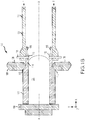
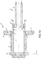
- catcher 124 comprise and be coupled by clamps 127 as shown in FIG. 1C , grabbers 130 having a grabbing surface 132 as shown in FIG. 1D , or other such suitable coupling mechanism.
- clamps 127 and grabbers 130 may be mechanically, electro-mechanically, or hydraulically actuated tending thereby to apply a coupling force between clamps 127 or grabbers 130 and traveling end 122.
- grabbing surface 132 may comprise hardened metallic grip enhancing features such as points, cones, pyramids, ridges, teeth, or other suitable feature tending to bite into the material of traveling end 122 and, in that regard, tending to enhance the coupling between catcher 124 and work piece 114.
- catcher 124 When coupled to work piece 114, catcher 124 is coaxial to mandrel 104 and rotates synchronously with work piece 114 and mandrel 104 about axis A-A. In various embodiments, catcher 124 travels (along x-axis) with flow 116 of work piece 114 and tends to support work piece 114 as traveling end 122 moves away from mandrel 104.
- apparatus 100 may comprise sensors 128 which may be configured to transmit measured characteristics of apparatus 100 to a controller 202 ( FIG. 2 described below), thereby providing sensor feedback about apparatus 100.
- the measured characteristics may comprise one of a tension parameter, a deflection parameter, a catcher parameter, or an apparatus parameter.
- the sensor feedback may be, for example position feedback, temperature feedback, pressure feedback, shaft speed, or other data.
- controller 202 may determine a tension T between the work piece 114 and the catcher 124.
- the tension T may be a function of a total required deformation ratio and a material property of the material.
- catcher 124 may be configured to oscillate rotationally with respect to the rotational axis and tending thereby to cause traveling end 122 of work piece 114 to deflect relative to axis A-A.
- work piece 114 tends to have a higher strength than the material at plastic deformation zones 112 and tends to transfer the oscillations into the plastic deformation zones 112.
- the oscillation of catcher 124 may tend to trigger a plastic deformation in a localized zone of shear bands tending thereby to reduce material stresses in the plastic deformation zones and, in response, tending to improve material formability, tending to increase material microstructure homogeneity through the material thickness, and tending to reduce material susceptibility to cracking.
- compressive force F at rollers 108 may tend to be reduced in proportion to the improvement in material formability tending thereby to increase an operational life of rollers 108.
- the oscillations may be about 10° off axis A-A (i.e. a deflection as an absolute value) where the term "about” in this context means ⁇ 5°.
- mandrel 104 may be heated.
- preform 102 may be pre-heated prior to backward flow forming.
- a schematic diagram of a control system 200 for backward flow forming of shafts may comprise components of apparatus 100.
- Control system 200 may comprise controller 202 in communication with sensors 128 and catcher drive system 204.
- controller 202 may be in communication with roller drive system 214, mandrel drive system 216, and heating system 218.
- Systems in communication with controller 202 may receive commands 208 or signals from controller 202 such as to begin an oscillation, to adjust a tension, to alter an oscillation angle, to heat a component, or to alter a speed.
- controller 202 may comprise a processor.
- controller 202 may be implemented in a single processor or one or more processors configured to implement various logical operations in response to execution of instructions, for example, instructions stored on a non-transitory, tangible, computer-readable medium such as, for example, memory 210 which may store data used, for example, for trending and analysis/prognosis purposes.
- the one or more processors can be a general purpose processor, a microprocessor, a microcontroller, a digital signal processor (DSP), an application specific integrated circuit (ASIC), a field programmable gate array (FPGA) or other programmable logic device, discrete gate or transistor logic, discrete hardware components, or any combination thereof.
- controller 202 may receive and interpret off board data 212 which may comprise configuration data, prerecorded data, external commands, or any other data. In various embodiments, controller 202 may receive and interpret data from one or more sensors 128 located throughout apparatus 100. In various embodiments, controller 202 may receive and interpret sensor data to determine the tension T between the work piece 114 and the catcher 124 and, in response, command catcher drive system 204 to adjust a catcher position tending thereby to alter tension T. In various embodiments, controller 202 may dynamically adjust the catcher position to maintain a constant tension.
- off board data 212 may comprise an external command of the form "start flow forming" or "stop flow forming” and controller 202 may command one of the catcher drive system 204, the roller drive system 214, or the mandrel drive system 216 in response to the external command.
- Method 300 includes mounting the material in an apparatus for backward flow forming (step 302).
- method 300 may include heating a mandrel (step 304).
- Method 300 includes applying a load to a plurality of rollers and forming a plastic deformation zone in the material between the plurality of rollers and the mandrel (step 306).
- Method 300 includes advancing the plurality of rollers toward a headstock at a proximate end of the mandrel (step 306), wherein a work piece flows from the plastic deformation zone between the plurality of rollers and the mandrel toward a distal end of the mandrel.
- Method 300 includes coupling the work piece to a catcher at a traveling end of the work piece (step 308).
- step 308 may further comprise machining a coupling feature in the work piece proximate the traveling end of the work piece.
- Method 300 includes applying a tension defined between the catcher and the plastic deformation zone at the traveling end of the work piece (step 310).
- Method 300 includes deflecting the traveling end of the work piece with respect to an axis of the mandrel (step 312).
- Method 300 includes forming shear banding within the material at the plastic deformation zone in response to the deflection (step 314).
- references to "various embodiments,” “one embodiment,” “an embodiment,” “an example embodiment,” etc. indicate that the embodiment described may include a particular feature, structure, or characteristic, but every embodiment may not necessarily include the particular feature, structure, or characteristic. Moreover, such phrases are not necessarily referring to the same embodiment. Further, when a particular feature, structure, or characteristic is described in connection with an embodiment, it is submitted that it is within the knowledge of one skilled in the art to affect such feature, structure, or characteristic in connection with other embodiments whether or not explicitly described. After reading the description, it will be apparent to one skilled in the relevant art(s) how to implement the disclosure in alternative embodiments.
Landscapes
- Engineering & Computer Science (AREA)
- Mechanical Engineering (AREA)
- Shaping Metal By Deep-Drawing, Or The Like (AREA)
Abstract
Description
- The present disclosure relates to flow forming of hollow shafts and more particularly to backward flow forming of hollow shafts.
- Flow forming technology is a metal forming technique whereby a hollow metal blank or preform is mounted on a rotating mandrel and the material of the preform may be made to flow (plastic deformation) axially, with respect to the mandrel, under pressure of one or more rollers. In this regard, the interior diameter of the work piece remains constant with respect to the diameter of the mandrel and the outer diameter of the work piece may be reduced.
- In various embodiments, an apparatus for backward flow forming a material is provided. The apparatus may comprise a mandrel having a headstock at a proximate end of the mandrel, the mandrel configured to rotate about an axis, a plurality of rollers disposed radially outward of the mandrel configured to exert force on the material to form a work piece at a plastic deformation zone, wherein the work piece flows from the plastic deformation zone between the plurality of rollers and the mandrel toward a distal end of the mandrel, and a catcher, coaxial to the mandrel, and removably coupled to the work piece at a traveling end of the work piece.
- In various embodiments, the traveling end further comprises a coupling feature. In various embodiments, the plurality of rollers are configured to travel from the distal end of the mandrel toward the headstock. In various embodiments, the catcher is configured to travel with the traveling end of the work piece. In various embodiments, the catcher exerts a tension in the work piece. In various embodiments, the catcher is configured to deflect the traveling end of the work piece with respect to the axis of the mandrel by oscillating with respect to the axis of the mandrel. In various embodiments, the deflection of the traveling end with respect to the axis of the mandrel is 5° to 15°. In various embodiments, shear banding is formed within the material at the plastic deformation zone in response to the deflection of the traveling end. In various embodiments, the catcher comprises one of a grab or a clamp. In various embodiments, the mandrel comprises a complex geometry having curves, multi-radial curves, or steps. In various embodiments, shear banding is formed within the material at the plastic deformation zone in response to the deflection of the roller. In various embodiments, the deflection of the roller with respect to the axis of the mandrel is 5° to 15°.
- In various embodiments, a method for improving backward flow forming of a material is provided. The method may comprise mounting the material in an apparatus for backward flow forming and applying a load to a plurality of rollers forming a plastic deformation zone in the material between the plurality of rollers and a mandrel, advancing the plurality of rollers toward a headstock at a proximate end of the mandrel, wherein a work piece flows from the plastic deformation zone between the plurality of rollers and the mandrel toward a distal end of the mandrel, and coupling the work piece to a catcher at a traveling end of the work piece.
- In various embodiments, the method may also comprise machining a coupling feature in the work piece proximate the traveling end of the work piece. In various embodiments, the method may also comprise applying a tension, defined between the catcher and the plastic deformation zone, at the traveling end of the work piece. In various embodiments, the coupling comprises clamping the work piece to the catcher. In various embodiments, the method may also comprise deflecting the traveling end of the work piece with respect to an axis of the mandrel. In various embodiments, the deflection with respect to the axis of the mandrel is 5° to 15°. In various embodiments, the method may also comprise forming shear banding within the material at the plastic deformation zone in response to the deflection.
- In various embodiments a control system for backward flow forming of shafts is provided. The system may comprise a first sensor in electronic communication with a controller, the first sensor configured to measure at least one of a tension parameter, a deflection parameter, a catcher parameter, or an apparatus parameter, a catcher drive system in electronic communication with the controller, and a tangible, non-transitory memory configured to communicate with the controller, the tangible, non-transitory memory having instructions stored thereon that, in response to execution by the controller, cause the controller to perform operations comprising receiving, by the controller, an external command and the first catcher parameter, and controlling, by the controller, the catcher drive system in response to the first catcher parameter and the external command.
- In various embodiments, the operations further comprise receiving, by the controller, the tension parameter and controlling, by the controller, the catcher drive system to maintain the tension parameter at a constant.
- The foregoing features and elements may be combined in various combinations without exclusivity, unless expressly indicated otherwise. These features and elements as well as the operation thereof will become more apparent in light of the following description and the accompanying drawings. It should be understood, however, the following description and drawings are intended to be exemplary in nature and non-limiting.
- The subject matter of the present disclosure is particularly pointed out and distinctly claimed in the concluding portion of the specification. A more complete understanding of the present disclosure, however, may best be obtained by referring to the detailed description and claims when considered in connection with the figures, wherein like numerals denote like elements.
-
FIG. 1A illustrates an apparatus for backward flow forming, in accordance with various embodiments; -
FIG. 1B illustrates an apparatus for backward flow forming, in accordance with various embodiments; -
FIG. 1C illustrates an apparatus for backward flow forming, in accordance with various embodiments; -
FIG. 1D illustrates an apparatus for backward flow forming, in accordance with various embodiments; -
FIG. 2 illustrates a control system for backward flow forming of shafts, in accordance with various embodiments; and -
FIG. 3 illustrates method for improving backward flow forming of a material, in accordance with various embodiments. - All ranges and ratio limits disclosed herein may be combined. It is to be understood that unless specifically stated otherwise, references to "a," "an," and/or "the" may include one or more than one and that reference to an item in the singular may also include the item in the plural.
- The detailed description of exemplary embodiments herein makes reference to the accompanying drawings, which show exemplary embodiments by way of illustration. While these exemplary embodiments are described in sufficient detail to enable those skilled in the art to practice the exemplary embodiments of the disclosure, it should be understood that other embodiments may be realized and that logical changes and adaptations in design and construction may be made in accordance with this disclosure and the teachings herein. Thus, the detailed description herein is presented for purposes of illustration only and not limitation.
- The scope of the disclosure is defined by the appended claims and their legal equivalents rather than by merely the examples described. For example, the steps recited in any of the method or process descriptions may be executed in any order and are not necessarily limited to the order presented. Furthermore, any reference to singular includes plural embodiments, and any reference to more than one component or step may include a singular embodiment or step. Also, any reference to attached, fixed, coupled, connected or the like may include permanent, removable, temporary, partial, full and/or any other possible attachment option. Additionally, any reference to without contact (or similar phrases) may also include reduced contact or minimal contact. Surface shading lines may be used throughout the figures to denote different parts but not necessarily to denote the same or different materials.
- Flow forming is a metal forming process whereby a hollow metal blank is mounted on a rotating mandrel and the metal is displaced axially along the mandrel by one or more rollers which traverse the length of the mandrel. In various embodiments, the metal blank may be a preform shape such as, for example, one of a sleeve or a cup. Flow forming may be performed either as backward flow forming or forward flow forming in accordance with the direction of axial flow during the flow forming process. In the forward flow forming technique, a blank is held between the mandrel and a tailstock while the rollers traverse from the tailstock along the mandrel tending thereby to displace material in the same direction as the traveling rollers. In various embodiments, forward flow forming tends to include a blank having a base or an internal flange or other such feature suitable for mounting in the tailstock. In the backward flow forming technique, a blank is held is held against a headstock and, as the rollers advance forward toward the headstock, the work piece is extruded backward between the roller and the mandrel.
- Backward flow forming tends to be suited for blank materials having low ductility, tending thereby to allow rollers to apply high force to plasticize the blank material under the contact point. In various embodiments, the flow of material under the rollers comprises two components an axial flow component along the axis of the mandrel and a circumferential flow component. In various embodiments, backward flow forming may be prone to non-uniform dimensioning across the length of the work piece which may result from the high forces used to plasticize materials having low ductility. In various embodiments, a backward flow forming work piece may tend to sag or deform under its own weight and/or lose concentricity as the work piece travels away from the mandrel. In various embodiments, a lack of plasticity may tend to cause distortions like bell mouthing at a free end of the work piece or a preform. In various embodiments, a lack of plasticity may require a multiple-pass flow forming with or without annealing step in between. In various embodiments, a lack of plasticity in the blank material and the work piece (i.e. low ductility) may tend to increase friction against the mandrel and may tend to induce bulging and cracking of the work piece and/or the blank material.
- In various embodiments and with reference to
FIG. 1A , anapparatus 100 for backward flow forming is illustrated comprising amandrel 104 and aheadstock 106 at a proximate end ofmandrel 104. Apreform 102 is mounted onmandrel 104 and rotates withmandrel 104 about axis A-A. One ormore rollers 108 apply a compressive force F to preform 102 and roll circumferentially along the surface ofpreform 102 in response to the rotation ofmandrel 104. In various embodiments, a mandrel such asmandrel 104 may have a generally cylindrical geometry or may comprise a complex geometry having a curves, multi-radial curves, or steps and, in this regard, the circumference of a mandrel such asmandrel 104 may vary with respect to a position along axis A-A. In response to the compressive force and rolling,plastic deformation zones 112 are formed in thepreform 102 between therollers 108 and themandrel 104.Plastic deformation zones 112 advance along thepreform 102 in response torollers 108 advancing towardheadstock 106 as shown byarrows 110. Asrollers 108 advance (arrows 110) awork piece 114 flows axially (along the positive x-axis) behind therollers 108 along thesurface 120 ofmandrel 104 toward a distal end ofmandrel 104. Asrollers 108shape preform 102 to the desired diameter,work piece 114 continues to flow along and away frommandrel 104 as shown byarrows 116. In various embodiments, coupling features 118 such as, for example, flats, a flange or holes bored through the work piece, may be formed proximate travelingend 122 ofwork piece 114. In various embodiments, coupling features 118 may be formed in response to travelingend 122 departing themandrel 104. In various embodiments, a preform such aspreform 102 may comprise pre-machined coupling features (i.e. coupling features machined prior to flow forming) which may be excised and discarded from the traveling end of the work piece subsequent to the backward flow forming of the preform. - With additional reference to
FIG. 1B through FIG. ID,apparatus 100 for backward flow forming is illustrated withcatcher 124 removably coupled at coupling features 118 to workpiece 114 by lockingpins 126. In various embodiments,catcher 124 comprise and be coupled byclamps 127 as shown inFIG. 1C ,grabbers 130 having a grabbingsurface 132 as shown inFIG. 1D , or other such suitable coupling mechanism. In various embodiments, clamps 127 andgrabbers 130 may be mechanically, electro-mechanically, or hydraulically actuated tending thereby to apply a coupling force betweenclamps 127 orgrabbers 130 and travelingend 122. In various embodiments, grabbingsurface 132 may comprise hardened metallic grip enhancing features such as points, cones, pyramids, ridges, teeth, or other suitable feature tending to bite into the material of travelingend 122 and, in that regard, tending to enhance the coupling betweencatcher 124 andwork piece 114.. When coupled towork piece 114,catcher 124 is coaxial to mandrel 104 and rotates synchronously withwork piece 114 andmandrel 104 about axis A-A. In various embodiments,catcher 124 travels (along x-axis) withflow 116 ofwork piece 114 and tends to supportwork piece 114 as travelingend 122 moves away frommandrel 104. In this regard,catcher 124 tends to reduce sag or deformation ofwork piece 114 under its own weight and tends to reduce loss of concentricity inwork piece 114. In various embodiments,catcher 124 may apply a tension T to thework piece 114 while traveling with theflow 116 of material. In various embodiments,apparatus 100 may comprisesensors 128 which may be configured to transmit measured characteristics ofapparatus 100 to a controller 202 (FIG. 2 described below), thereby providing sensor feedback aboutapparatus 100. In various embodiments, the measured characteristics may comprise one of a tension parameter, a deflection parameter, a catcher parameter, or an apparatus parameter. The sensor feedback may be, for example position feedback, temperature feedback, pressure feedback, shaft speed, or other data. In this regard,controller 202 may determine a tension T between thework piece 114 and thecatcher 124. In various embodiments, the tension T may be a function of a total required deformation ratio and a material property of the material. - In various embodiments,
catcher 124 may be configured to oscillate rotationally with respect to the rotational axis and tending thereby to cause travelingend 122 ofwork piece 114 to deflect relative to axis A-A. In various embodiments,work piece 114 tends to have a higher strength than the material atplastic deformation zones 112 and tends to transfer the oscillations into theplastic deformation zones 112. In this regard, the oscillation ofcatcher 124 may tend to trigger a plastic deformation in a localized zone of shear bands tending thereby to reduce material stresses in the plastic deformation zones and, in response, tending to improve material formability, tending to increase material microstructure homogeneity through the material thickness, and tending to reduce material susceptibility to cracking. In this regard, compressive force F atrollers 108 may tend to be reduced in proportion to the improvement in material formability tending thereby to increase an operational life ofrollers 108. In various embodiments, the oscillations may be about 10° off axis A-A (i.e. a deflection as an absolute value) where the term "about" in this context means ± 5°. Stated another way, aswork piece 114 continues to flow along and away frommandrel 104 the oscillations may tend to cause travelingend 122 ofwork piece 114 to trace a sinusoidal path with axis A-A defining a relative zero position of the wave form traced by travelingend 122. In various embodiments,mandrel 104 may be heated. In various embodiments, preform 102 may be pre-heated prior to backward flow forming. - In various embodiments and with reference to
FIG. 2 , a schematic diagram of acontrol system 200 for backward flow forming of shafts may comprise components ofapparatus 100.Control system 200 may comprisecontroller 202 in communication withsensors 128 andcatcher drive system 204. In various embodiments,controller 202 may be in communication withroller drive system 214,mandrel drive system 216, andheating system 218. Systems in communication withcontroller 202 may receivecommands 208 or signals fromcontroller 202 such as to begin an oscillation, to adjust a tension, to alter an oscillation angle, to heat a component, or to alter a speed. In various embodiments,controller 202 may comprise a processor. In various embodiments,controller 202 may be implemented in a single processor or one or more processors configured to implement various logical operations in response to execution of instructions, for example, instructions stored on a non-transitory, tangible, computer-readable medium such as, for example,memory 210 which may store data used, for example, for trending and analysis/prognosis purposes. The one or more processors can be a general purpose processor, a microprocessor, a microcontroller, a digital signal processor (DSP), an application specific integrated circuit (ASIC), a field programmable gate array (FPGA) or other programmable logic device, discrete gate or transistor logic, discrete hardware components, or any combination thereof. In various embodiments,controller 202 may receive and interpret offboard data 212 which may comprise configuration data, prerecorded data, external commands, or any other data. In various embodiments,controller 202 may receive and interpret data from one ormore sensors 128 located throughoutapparatus 100. In various embodiments,controller 202 may receive and interpret sensor data to determine the tension T between thework piece 114 and thecatcher 124 and, in response, commandcatcher drive system 204 to adjust a catcher position tending thereby to alter tension T. In various embodiments,controller 202 may dynamically adjust the catcher position to maintain a constant tension. In various embodiments, offboard data 212 may comprise an external command of the form "start flow forming" or "stop flow forming" andcontroller 202 may command one of thecatcher drive system 204, theroller drive system 214, or themandrel drive system 216 in response to the external command. - With reference to
FIG. 3 , amethod 300 for improving backward flow forming of a material is illustrated in accordance with various embodiments.Method 300 includes mounting the material in an apparatus for backward flow forming (step 302). In various embodiments,method 300 may include heating a mandrel (step 304).Method 300 includes applying a load to a plurality of rollers and forming a plastic deformation zone in the material between the plurality of rollers and the mandrel (step 306).Method 300 includes advancing the plurality of rollers toward a headstock at a proximate end of the mandrel (step 306), wherein a work piece flows from the plastic deformation zone between the plurality of rollers and the mandrel toward a distal end of the mandrel.Method 300 includes coupling the work piece to a catcher at a traveling end of the work piece (step 308). In various embodiments,step 308 may further comprise machining a coupling feature in the work piece proximate the traveling end of the work piece.Method 300 includes applying a tension defined between the catcher and the plastic deformation zone at the traveling end of the work piece (step 310).Method 300 includes deflecting the traveling end of the work piece with respect to an axis of the mandrel (step 312).Method 300 includes forming shear banding within the material at the plastic deformation zone in response to the deflection (step 314). - Benefits and other advantages have been described herein with regard to specific embodiments. Furthermore, the connecting lines shown in the various figures contained herein are intended to represent exemplary functional relationships and/or physical couplings between the various elements. It should be noted that many alternative or additional functional relationships or physical connections may be present in a practical system. However, the benefits, advantages, and any elements that may cause any benefit or advantage to occur or become more pronounced are not to be construed as critical, required, or essential features or elements of the disclosure. The scope of the disclosure is accordingly to be limited by nothing other than the appended claims, in which reference to an element in the singular is not intended to mean "one and only one" unless explicitly so stated, but rather "one or more." Moreover, where a phrase similar to "at least one of A, B, or C" is used in the claims, it is intended that the phrase be interpreted to mean that A alone may be present in an embodiment, B alone may be present in an embodiment, C alone may be present in an embodiment, or that any combination of the elements A, B and C may be present in a single embodiment; for example, A and B, A and C, B and C, or A and B and C.
- Systems, methods and apparatus are provided herein. In the detailed description herein, references to "various embodiments," "one embodiment," "an embodiment," "an example embodiment," etc., indicate that the embodiment described may include a particular feature, structure, or characteristic, but every embodiment may not necessarily include the particular feature, structure, or characteristic. Moreover, such phrases are not necessarily referring to the same embodiment. Further, when a particular feature, structure, or characteristic is described in connection with an embodiment, it is submitted that it is within the knowledge of one skilled in the art to affect such feature, structure, or characteristic in connection with other embodiments whether or not explicitly described. After reading the description, it will be apparent to one skilled in the relevant art(s) how to implement the disclosure in alternative embodiments.
- Furthermore, no element, component, or method step in the present disclosure is intended to be dedicated to the public regardless of whether the element, component, or method step is explicitly recited in the claims. No claim element herein is invoke 35 U.S.C. 112(f) unless the element is expressly recited using the phrase "means for." As used herein, the terms "comprises," "comprising," or any other variation thereof, are intended to cover a non-exclusive inclusion, such that a process, method, article, or apparatus that comprises a list of elements does not include only those elements but may include other elements not expressly listed or inherent to such process, method, article, or apparatus.
Claims (15)
- An apparatus for backward flow forming a material comprising:a mandrel having a headstock at a proximate end of the mandrel, the mandrel configured to rotate about an axis;a plurality of rollers disposed radially outward of the mandrel configured to exert force on the material to form a work piece at a plastic deformation zone, wherein the work piece flows from the plastic deformation zone between the plurality of rollers and the mandrel toward a distal end of the mandrel; anda catcher, coaxial to the mandrel, and removably coupled to the work piece at a traveling end of the work piece.
- The apparatus of claim 1, wherein the traveling end further comprises a coupling feature.
- The apparatus of claim 1 or 2, wherein the plurality of rollers are configured to travel from the distal end of the mandrel toward the headstock.
- The apparatus of claim 1, 2 or 3, wherein the catcher is configured to travel with the traveling end of the work piece.
- The apparatus of claim 4, wherein the catcher exerts a tension in the work piece.
- The apparatus of claim 5, wherein the catcher is configured to deflect the traveling end of the work piece with respect to the axis of the mandrel by oscillating with respect to the axis of the mandrel.
- The apparatus of claim 6, wherein the deflection of the traveling end with respect to the axis of the mandrel is 5° to 15°.
- The apparatus of claim 7, wherein shear banding is formed within the material at the plastic deformation zone in response to the deflection of the traveling end.
- The apparatus of any of claims 5 to 8 wherein the catcher comprises one of a grab or a clamp.
- The apparatus of any of claims 5 to 9, wherein the mandrel comprises a complex geometry having curves, multi-radial curves, or steps,
wherein, optionally, shear banding is formed within the material at the plastic deformation zone in response to the deflection of at least one of the plurality of rollers,
wherein, optionally, the deflection of the at least one of the plurality of rollers with respect to the axis of the mandrel is 5° to 15°. - A method for improving backward flow forming of a material, comprising:mounting the material in an apparatus for backward flow forming and applying a load to a plurality of rollers forming a plastic deformation zone in the material between the plurality of rollers and a mandrel;advancing the plurality of rollers toward a headstock at a proximate end of the mandrel forming a work piece, wherein the work piece flows from the plastic deformation zone between the plurality of rollers and the mandrel toward a distal end of the mandrel; andcoupling the work piece to a catcher at a traveling end of the work piece.
- The method of claim 11, further comprising machining a coupling feature in the work piece proximate the traveling end of the work piece.
- The method of claim 11 or 12, further comprising applying a tension, defined between the catcher and the plastic deformation zone, at the traveling end of the work piece,
wherein, optionally, the coupling comprises clamping the work piece to the catcher. - The method of claim 13, further comprising deflecting one of the traveling end of the work piece with respect to an axis of the mandrel,
wherein, optionally, the deflection with respect to the axis of the mandrel is 5° to 15°, and/or
optionally further comprising forming shear banding within the material at the plastic deformation zone in response to the deflection. - A control system for backward flow forming of shafts comprising:a first sensor in electronic communication with a controller, the first sensor configured to measure at least one of a tension parameter, a deflection parameter, a catcher parameter, or an apparatus parameter;a catcher drive system in electronic communication with the controller; anda tangible, non-transitory memory configured to communicate with the controller, the tangible, non-transitory memory having instructions stored thereon that, in response to execution by the controller, cause the controller to perform operations comprising:receiving, by the controller, an external command and the catcher parameter; andcontrolling, by the controller, the catcher drive system in response to the catcher parameter and the external command.
Applications Claiming Priority (1)
| Application Number | Priority Date | Filing Date | Title |
|---|---|---|---|
| US15/934,500 US11185905B2 (en) | 2018-03-23 | 2018-03-23 | Systems and methods for improving backward flow forming of shafts |
Publications (2)
| Publication Number | Publication Date |
|---|---|
| EP3542918A1 true EP3542918A1 (en) | 2019-09-25 |
| EP3542918B1 EP3542918B1 (en) | 2021-08-25 |
Family
ID=65904107
Family Applications (1)
| Application Number | Title | Priority Date | Filing Date |
|---|---|---|---|
| EP19164061.4A Active EP3542918B1 (en) | 2018-03-23 | 2019-03-20 | Apparatus and method for improving backward flow forming of shafts |
Country Status (2)
| Country | Link |
|---|---|
| US (3) | US11185905B2 (en) |
| EP (1) | EP3542918B1 (en) |
Cited By (2)
| Publication number | Priority date | Publication date | Assignee | Title |
|---|---|---|---|---|
| CN112536404A (en) * | 2019-10-29 | 2021-03-23 | 北京机电研究所有限公司 | Method for roll forging and forming hollow train axle |
| IT202200004430A1 (en) * | 2022-03-09 | 2023-09-09 | Univ Degli Studi Padova | EQUIPMENT FOR THE FLUO-FORMING OF PRODUCTS, TO BE INSTALLED IN A MACHINE PARTICULARLY OF THE TYPE EQUIPPED WITH MEANS WITH WHICH TO ROTATE AN PRODUCT TO BE PROCESSED AND PROCEDURE FOR THE FLUO-FORMING OF PRODUCTS |
Families Citing this family (2)
| Publication number | Priority date | Publication date | Assignee | Title |
|---|---|---|---|---|
| US11185905B2 (en) * | 2018-03-23 | 2021-11-30 | Raytheon Technologies Corporation | Systems and methods for improving backward flow forming of shafts |
| CN113118285A (en) * | 2021-04-08 | 2021-07-16 | 内蒙古航天红岗机械有限公司 | Engine housing derotation blank positioning tool |
Citations (5)
| Publication number | Priority date | Publication date | Assignee | Title |
|---|---|---|---|---|
| FR2190243A5 (en) * | 1972-06-22 | 1974-01-25 | Leifeld & Co | |
| NL7302082A (en) * | 1972-10-24 | 1974-04-26 | ||
| US20070059460A1 (en) * | 2005-09-09 | 2007-03-15 | Applied Materials, Inc. | Flow-formed chamber component having a textured surface |
| US20160033059A1 (en) * | 2014-06-27 | 2016-02-04 | Ati Properties, Inc. | Flowforming corrosion resistant alloy tubes |
| DE102015109433A1 (en) * | 2015-06-12 | 2016-12-15 | WF Maschinenbau und Blechformtechnik GmbH & Co. KG | Method and device for wall deformation of a tubular workpiece |
Family Cites Families (6)
| Publication number | Priority date | Publication date | Assignee | Title |
|---|---|---|---|---|
| US2942337A (en) * | 1954-05-28 | 1960-06-28 | Buderus Eisenwerk | Process for the treatment of thickwalled metallic hollow bodies |
| DE102006001064B4 (en) * | 2006-01-07 | 2010-12-16 | Sms Meer Gmbh | Process for making a seamless pipe |
| US20100236122A1 (en) | 2006-07-26 | 2010-09-23 | Fonte Matthew V | Flowforming Gun Barrels and Similar Tubular Devices |
| US9291057B2 (en) | 2012-07-18 | 2016-03-22 | United Technologies Corporation | Tie shaft for gas turbine engine and flow forming method for manufacturing same |
| GB201316829D0 (en) | 2013-09-23 | 2013-11-06 | Rolls Royce Plc | Flow Forming method |
| US11185905B2 (en) * | 2018-03-23 | 2021-11-30 | Raytheon Technologies Corporation | Systems and methods for improving backward flow forming of shafts |
-
2018
- 2018-03-23 US US15/934,500 patent/US11185905B2/en active Active
-
2019
- 2019-03-20 EP EP19164061.4A patent/EP3542918B1/en active Active
-
2021
- 2021-10-28 US US17/513,720 patent/US12194522B2/en active Active
-
2024
- 2024-12-12 US US18/979,214 patent/US20250108425A1/en active Pending
Patent Citations (5)
| Publication number | Priority date | Publication date | Assignee | Title |
|---|---|---|---|---|
| FR2190243A5 (en) * | 1972-06-22 | 1974-01-25 | Leifeld & Co | |
| NL7302082A (en) * | 1972-10-24 | 1974-04-26 | ||
| US20070059460A1 (en) * | 2005-09-09 | 2007-03-15 | Applied Materials, Inc. | Flow-formed chamber component having a textured surface |
| US20160033059A1 (en) * | 2014-06-27 | 2016-02-04 | Ati Properties, Inc. | Flowforming corrosion resistant alloy tubes |
| DE102015109433A1 (en) * | 2015-06-12 | 2016-12-15 | WF Maschinenbau und Blechformtechnik GmbH & Co. KG | Method and device for wall deformation of a tubular workpiece |
Cited By (2)
| Publication number | Priority date | Publication date | Assignee | Title |
|---|---|---|---|---|
| CN112536404A (en) * | 2019-10-29 | 2021-03-23 | 北京机电研究所有限公司 | Method for roll forging and forming hollow train axle |
| IT202200004430A1 (en) * | 2022-03-09 | 2023-09-09 | Univ Degli Studi Padova | EQUIPMENT FOR THE FLUO-FORMING OF PRODUCTS, TO BE INSTALLED IN A MACHINE PARTICULARLY OF THE TYPE EQUIPPED WITH MEANS WITH WHICH TO ROTATE AN PRODUCT TO BE PROCESSED AND PROCEDURE FOR THE FLUO-FORMING OF PRODUCTS |
Also Published As
| Publication number | Publication date |
|---|---|
| EP3542918B1 (en) | 2021-08-25 |
| US20220048089A1 (en) | 2022-02-17 |
| US11185905B2 (en) | 2021-11-30 |
| US20250108425A1 (en) | 2025-04-03 |
| US20190291167A1 (en) | 2019-09-26 |
| US12194522B2 (en) | 2025-01-14 |
Similar Documents
| Publication | Publication Date | Title |
|---|---|---|
| US12194522B2 (en) | Systems and methods for improving backward flow forming of shafts | |
| AU2016214838B2 (en) | Apparatus and method for mobile friction stir welding of two tubular structures | |
| KR101753445B1 (en) | Manufacturing method of aluminum alloy propeller shaft using friction welding process | |
| CN104487185B (en) | Spinforming apparatus and forming method | |
| EP3096933B1 (en) | Method and device for manufacturing pipe shells and pipe shell manufactured therewith | |
| CN205834846U (en) | A kind of for precise thin-wall tubular member clamp for machining | |
| JP2011005570A (en) | Apparatus and method of cutting and burnishing | |
| US20100199740A1 (en) | Method of and apparatus for making pipe from a tubular workpiece | |
| JP2014173603A (en) | Device for positioning at least one functional component | |
| US9656365B1 (en) | Honing tool and method | |
| EP1946861B1 (en) | Closing device and closing method | |
| CN106061644A (en) | Method for manufacturing preform and axially-symmetric component | |
| US20260061473A1 (en) | Near-isothermal hot spin forming method and heat complementing method for metal workpiece | |
| JP6722946B2 (en) | Spinning machine | |
| JP2014188522A (en) | Method for molding cylindrical material | |
| JP2615034B2 (en) | Automatic grinding method and equipment | |
| JP5988301B2 (en) | Upsetting method for materials having pipe-shaped parts | |
| CN203437942U (en) | Adjustable self-centering inner supporting device for machining thin walled tube part | |
| JP3624017B2 (en) | Hot bending method for metal pipe | |
| CN109354393B (en) | Forming and processing device for contraction and expansion type glass micro-spraying pipe | |
| US20210220901A1 (en) | Method for manufacturing steering shaft of steering device | |
| JPH0647432A (en) | Manufacture of metal tube having thin part and apparatus therefor | |
| JP6509348B2 (en) | Method and apparatus for processing tubular member | |
| JP2507749B2 (en) | Thin wall pipe thickening equipment | |
| JP6446968B2 (en) | Method and apparatus for forming cylindrical member |
Legal Events
| Date | Code | Title | Description |
|---|---|---|---|
| PUAI | Public reference made under article 153(3) epc to a published international application that has entered the european phase |
Free format text: ORIGINAL CODE: 0009012 |
|
| STAA | Information on the status of an ep patent application or granted ep patent |
Free format text: STATUS: THE APPLICATION HAS BEEN PUBLISHED |
|
| AK | Designated contracting states |
Kind code of ref document: A1 Designated state(s): AL AT BE BG CH CY CZ DE DK EE ES FI FR GB GR HR HU IE IS IT LI LT LU LV MC MK MT NL NO PL PT RO RS SE SI SK SM TR |
|
| AX | Request for extension of the european patent |
Extension state: BA ME |
|
| STAA | Information on the status of an ep patent application or granted ep patent |
Free format text: STATUS: REQUEST FOR EXAMINATION WAS MADE |
|
| 17P | Request for examination filed |
Effective date: 20200325 |
|
| RBV | Designated contracting states (corrected) |
Designated state(s): AL AT BE BG CH CY CZ DE DK EE ES FI FR GB GR HR HU IE IS IT LI LT LU LV MC MK MT NL NO PL PT RO RS SE SI SK SM TR |
|
| STAA | Information on the status of an ep patent application or granted ep patent |
Free format text: STATUS: EXAMINATION IS IN PROGRESS |
|
| 17Q | First examination report despatched |
Effective date: 20200622 |
|
| GRAP | Despatch of communication of intention to grant a patent |
Free format text: ORIGINAL CODE: EPIDOSNIGR1 |
|
| STAA | Information on the status of an ep patent application or granted ep patent |
Free format text: STATUS: GRANT OF PATENT IS INTENDED |
|
| RAP1 | Party data changed (applicant data changed or rights of an application transferred) |
Owner name: RAYTHEON TECHNOLOGIES CORPORATION |
|
| INTG | Intention to grant announced |
Effective date: 20210310 |
|
| GRAS | Grant fee paid |
Free format text: ORIGINAL CODE: EPIDOSNIGR3 |
|
| GRAA | (expected) grant |
Free format text: ORIGINAL CODE: 0009210 |
|
| STAA | Information on the status of an ep patent application or granted ep patent |
Free format text: STATUS: THE PATENT HAS BEEN GRANTED |
|
| AK | Designated contracting states |
Kind code of ref document: B1 Designated state(s): AL AT BE BG CH CY CZ DE DK EE ES FI FR GB GR HR HU IE IS IT LI LT LU LV MC MK MT NL NO PL PT RO RS SE SI SK SM TR |
|
| REG | Reference to a national code |
Ref country code: CH Ref legal event code: EP |
|
| REG | Reference to a national code |
Ref country code: IE Ref legal event code: FG4D Ref country code: AT Ref legal event code: REF Ref document number: 1423263 Country of ref document: AT Kind code of ref document: T Effective date: 20210915 |
|
| REG | Reference to a national code |
Ref country code: DE Ref legal event code: R096 Ref document number: 602019007057 Country of ref document: DE |
|
| REG | Reference to a national code |
Ref country code: LT Ref legal event code: MG9D |
|
| REG | Reference to a national code |
Ref country code: NL Ref legal event code: MP Effective date: 20210825 |
|
| REG | Reference to a national code |
Ref country code: AT Ref legal event code: MK05 Ref document number: 1423263 Country of ref document: AT Kind code of ref document: T Effective date: 20210825 |
|
| PG25 | Lapsed in a contracting state [announced via postgrant information from national office to epo] |
Ref country code: ES Free format text: LAPSE BECAUSE OF FAILURE TO SUBMIT A TRANSLATION OF THE DESCRIPTION OR TO PAY THE FEE WITHIN THE PRESCRIBED TIME-LIMIT Effective date: 20210825 Ref country code: FI Free format text: LAPSE BECAUSE OF FAILURE TO SUBMIT A TRANSLATION OF THE DESCRIPTION OR TO PAY THE FEE WITHIN THE PRESCRIBED TIME-LIMIT Effective date: 20210825 Ref country code: SE Free format text: LAPSE BECAUSE OF FAILURE TO SUBMIT A TRANSLATION OF THE DESCRIPTION OR TO PAY THE FEE WITHIN THE PRESCRIBED TIME-LIMIT Effective date: 20210825 Ref country code: RS Free format text: LAPSE BECAUSE OF FAILURE TO SUBMIT A TRANSLATION OF THE DESCRIPTION OR TO PAY THE FEE WITHIN THE PRESCRIBED TIME-LIMIT Effective date: 20210825 Ref country code: HR Free format text: LAPSE BECAUSE OF FAILURE TO SUBMIT A TRANSLATION OF THE DESCRIPTION OR TO PAY THE FEE WITHIN THE PRESCRIBED TIME-LIMIT Effective date: 20210825 Ref country code: PT Free format text: LAPSE BECAUSE OF FAILURE TO SUBMIT A TRANSLATION OF THE DESCRIPTION OR TO PAY THE FEE WITHIN THE PRESCRIBED TIME-LIMIT Effective date: 20211227 Ref country code: NO Free format text: LAPSE BECAUSE OF FAILURE TO SUBMIT A TRANSLATION OF THE DESCRIPTION OR TO PAY THE FEE WITHIN THE PRESCRIBED TIME-LIMIT Effective date: 20211125 Ref country code: LT Free format text: LAPSE BECAUSE OF FAILURE TO SUBMIT A TRANSLATION OF THE DESCRIPTION OR TO PAY THE FEE WITHIN THE PRESCRIBED TIME-LIMIT Effective date: 20210825 Ref country code: AT Free format text: LAPSE BECAUSE OF FAILURE TO SUBMIT A TRANSLATION OF THE DESCRIPTION OR TO PAY THE FEE WITHIN THE PRESCRIBED TIME-LIMIT Effective date: 20210825 Ref country code: BG Free format text: LAPSE BECAUSE OF FAILURE TO SUBMIT A TRANSLATION OF THE DESCRIPTION OR TO PAY THE FEE WITHIN THE PRESCRIBED TIME-LIMIT Effective date: 20211125 |
|
| PG25 | Lapsed in a contracting state [announced via postgrant information from national office to epo] |
Ref country code: PL Free format text: LAPSE BECAUSE OF FAILURE TO SUBMIT A TRANSLATION OF THE DESCRIPTION OR TO PAY THE FEE WITHIN THE PRESCRIBED TIME-LIMIT Effective date: 20210825 Ref country code: LV Free format text: LAPSE BECAUSE OF FAILURE TO SUBMIT A TRANSLATION OF THE DESCRIPTION OR TO PAY THE FEE WITHIN THE PRESCRIBED TIME-LIMIT Effective date: 20210825 Ref country code: GR Free format text: LAPSE BECAUSE OF FAILURE TO SUBMIT A TRANSLATION OF THE DESCRIPTION OR TO PAY THE FEE WITHIN THE PRESCRIBED TIME-LIMIT Effective date: 20211126 |
|
| PG25 | Lapsed in a contracting state [announced via postgrant information from national office to epo] |
Ref country code: NL Free format text: LAPSE BECAUSE OF FAILURE TO SUBMIT A TRANSLATION OF THE DESCRIPTION OR TO PAY THE FEE WITHIN THE PRESCRIBED TIME-LIMIT Effective date: 20210825 |
|
| PG25 | Lapsed in a contracting state [announced via postgrant information from national office to epo] |
Ref country code: DK Free format text: LAPSE BECAUSE OF FAILURE TO SUBMIT A TRANSLATION OF THE DESCRIPTION OR TO PAY THE FEE WITHIN THE PRESCRIBED TIME-LIMIT Effective date: 20210825 |
|
| REG | Reference to a national code |
Ref country code: DE Ref legal event code: R097 Ref document number: 602019007057 Country of ref document: DE |
|
| PG25 | Lapsed in a contracting state [announced via postgrant information from national office to epo] |
Ref country code: SM Free format text: LAPSE BECAUSE OF FAILURE TO SUBMIT A TRANSLATION OF THE DESCRIPTION OR TO PAY THE FEE WITHIN THE PRESCRIBED TIME-LIMIT Effective date: 20210825 Ref country code: SK Free format text: LAPSE BECAUSE OF FAILURE TO SUBMIT A TRANSLATION OF THE DESCRIPTION OR TO PAY THE FEE WITHIN THE PRESCRIBED TIME-LIMIT Effective date: 20210825 Ref country code: RO Free format text: LAPSE BECAUSE OF FAILURE TO SUBMIT A TRANSLATION OF THE DESCRIPTION OR TO PAY THE FEE WITHIN THE PRESCRIBED TIME-LIMIT Effective date: 20210825 Ref country code: EE Free format text: LAPSE BECAUSE OF FAILURE TO SUBMIT A TRANSLATION OF THE DESCRIPTION OR TO PAY THE FEE WITHIN THE PRESCRIBED TIME-LIMIT Effective date: 20210825 Ref country code: CZ Free format text: LAPSE BECAUSE OF FAILURE TO SUBMIT A TRANSLATION OF THE DESCRIPTION OR TO PAY THE FEE WITHIN THE PRESCRIBED TIME-LIMIT Effective date: 20210825 Ref country code: AL Free format text: LAPSE BECAUSE OF FAILURE TO SUBMIT A TRANSLATION OF THE DESCRIPTION OR TO PAY THE FEE WITHIN THE PRESCRIBED TIME-LIMIT Effective date: 20210825 |
|
| PLBE | No opposition filed within time limit |
Free format text: ORIGINAL CODE: 0009261 |
|
| STAA | Information on the status of an ep patent application or granted ep patent |
Free format text: STATUS: NO OPPOSITION FILED WITHIN TIME LIMIT |
|
| PG25 | Lapsed in a contracting state [announced via postgrant information from national office to epo] |
Ref country code: IT Free format text: LAPSE BECAUSE OF FAILURE TO SUBMIT A TRANSLATION OF THE DESCRIPTION OR TO PAY THE FEE WITHIN THE PRESCRIBED TIME-LIMIT Effective date: 20210825 |
|
| 26N | No opposition filed |
Effective date: 20220527 |
|
| PG25 | Lapsed in a contracting state [announced via postgrant information from national office to epo] |
Ref country code: SI Free format text: LAPSE BECAUSE OF FAILURE TO SUBMIT A TRANSLATION OF THE DESCRIPTION OR TO PAY THE FEE WITHIN THE PRESCRIBED TIME-LIMIT Effective date: 20210825 |
|
| PG25 | Lapsed in a contracting state [announced via postgrant information from national office to epo] |
Ref country code: MC Free format text: LAPSE BECAUSE OF FAILURE TO SUBMIT A TRANSLATION OF THE DESCRIPTION OR TO PAY THE FEE WITHIN THE PRESCRIBED TIME-LIMIT Effective date: 20210825 |
|
| REG | Reference to a national code |
Ref country code: CH Ref legal event code: PL |
|
| REG | Reference to a national code |
Ref country code: BE Ref legal event code: MM Effective date: 20220331 |
|
| PG25 | Lapsed in a contracting state [announced via postgrant information from national office to epo] |
Ref country code: LU Free format text: LAPSE BECAUSE OF NON-PAYMENT OF DUE FEES Effective date: 20220320 Ref country code: LI Free format text: LAPSE BECAUSE OF NON-PAYMENT OF DUE FEES Effective date: 20220331 Ref country code: IE Free format text: LAPSE BECAUSE OF NON-PAYMENT OF DUE FEES Effective date: 20220320 Ref country code: CH Free format text: LAPSE BECAUSE OF NON-PAYMENT OF DUE FEES Effective date: 20220331 |
|
| PG25 | Lapsed in a contracting state [announced via postgrant information from national office to epo] |
Ref country code: BE Free format text: LAPSE BECAUSE OF NON-PAYMENT OF DUE FEES Effective date: 20220331 |
|
| P01 | Opt-out of the competence of the unified patent court (upc) registered |
Effective date: 20230521 |
|
| PG25 | Lapsed in a contracting state [announced via postgrant information from national office to epo] |
Ref country code: MK Free format text: LAPSE BECAUSE OF FAILURE TO SUBMIT A TRANSLATION OF THE DESCRIPTION OR TO PAY THE FEE WITHIN THE PRESCRIBED TIME-LIMIT Effective date: 20210825 Ref country code: CY Free format text: LAPSE BECAUSE OF FAILURE TO SUBMIT A TRANSLATION OF THE DESCRIPTION OR TO PAY THE FEE WITHIN THE PRESCRIBED TIME-LIMIT Effective date: 20210825 |
|
| PG25 | Lapsed in a contracting state [announced via postgrant information from national office to epo] |
Ref country code: HU Free format text: LAPSE BECAUSE OF FAILURE TO SUBMIT A TRANSLATION OF THE DESCRIPTION OR TO PAY THE FEE WITHIN THE PRESCRIBED TIME-LIMIT; INVALID AB INITIO Effective date: 20190320 |
|
| PG25 | Lapsed in a contracting state [announced via postgrant information from national office to epo] |
Ref country code: MT Free format text: LAPSE BECAUSE OF FAILURE TO SUBMIT A TRANSLATION OF THE DESCRIPTION OR TO PAY THE FEE WITHIN THE PRESCRIBED TIME-LIMIT Effective date: 20210825 |
|
| REG | Reference to a national code |
Ref country code: DE Ref legal event code: R081 Ref document number: 602019007057 Country of ref document: DE Owner name: RTX CORPORATION (N.D.GES.D. STAATES DELAWARE),, US Free format text: FORMER OWNER: RAYTHEON TECHNOLOGIES CORP., FARMINGTON, CT, US |
|
| PG25 | Lapsed in a contracting state [announced via postgrant information from national office to epo] |
Ref country code: TR Free format text: LAPSE BECAUSE OF FAILURE TO SUBMIT A TRANSLATION OF THE DESCRIPTION OR TO PAY THE FEE WITHIN THE PRESCRIBED TIME-LIMIT Effective date: 20210825 |
|
| PGFP | Annual fee paid to national office [announced via postgrant information from national office to epo] |
Ref country code: GB Payment date: 20260219 Year of fee payment: 8 |
|
| PGFP | Annual fee paid to national office [announced via postgrant information from national office to epo] |
Ref country code: DE Payment date: 20260219 Year of fee payment: 8 |
|
| PGFP | Annual fee paid to national office [announced via postgrant information from national office to epo] |
Ref country code: FR Payment date: 20260220 Year of fee payment: 8 |