EP3542689A1 - Accessoire batteur pour un appareil électroménager de préparation culinaire, equipé de fouet(s) facilement démontable(s) - Google Patents
Accessoire batteur pour un appareil électroménager de préparation culinaire, equipé de fouet(s) facilement démontable(s) Download PDFInfo
- Publication number
- EP3542689A1 EP3542689A1 EP19161735.6A EP19161735A EP3542689A1 EP 3542689 A1 EP3542689 A1 EP 3542689A1 EP 19161735 A EP19161735 A EP 19161735A EP 3542689 A1 EP3542689 A1 EP 3542689A1
- Authority
- EP
- European Patent Office
- Prior art keywords
- shaft
- whip
- rotation
- axis
- hub
- Prior art date
- Legal status (The legal status is an assumption and is not a legal conclusion. Google has not performed a legal analysis and makes no representation as to the accuracy of the status listed.)
- Granted
Links
Images

Classifications
-
- A—HUMAN NECESSITIES
- A47—FURNITURE; DOMESTIC ARTICLES OR APPLIANCES; COFFEE MILLS; SPICE MILLS; SUCTION CLEANERS IN GENERAL
- A47J—KITCHEN EQUIPMENT; COFFEE MILLS; SPICE MILLS; APPARATUS FOR MAKING BEVERAGES
- A47J43/00—Implements for preparing or holding food, not provided for in other groups of this subclass
- A47J43/04—Machines for domestic use not covered elsewhere, e.g. for grinding, mixing, stirring, kneading, emulsifying, whipping or beating foodstuffs, e.g. power-driven
- A47J43/046—Machines for domestic use not covered elsewhere, e.g. for grinding, mixing, stirring, kneading, emulsifying, whipping or beating foodstuffs, e.g. power-driven with tools driven from the bottom side
-
- A—HUMAN NECESSITIES
- A47—FURNITURE; DOMESTIC ARTICLES OR APPLIANCES; COFFEE MILLS; SPICE MILLS; SUCTION CLEANERS IN GENERAL
- A47J—KITCHEN EQUIPMENT; COFFEE MILLS; SPICE MILLS; APPARATUS FOR MAKING BEVERAGES
- A47J43/00—Implements for preparing or holding food, not provided for in other groups of this subclass
- A47J43/04—Machines for domestic use not covered elsewhere, e.g. for grinding, mixing, stirring, kneading, emulsifying, whipping or beating foodstuffs, e.g. power-driven
- A47J43/07—Parts or details, e.g. mixing tools, whipping tools
- A47J43/0716—Parts or details, e.g. mixing tools, whipping tools for machines with tools driven from the lower side
- A47J43/0722—Mixing, whipping or cutting tools
-
- A—HUMAN NECESSITIES
- A47—FURNITURE; DOMESTIC ARTICLES OR APPLIANCES; COFFEE MILLS; SPICE MILLS; SUCTION CLEANERS IN GENERAL
- A47J—KITCHEN EQUIPMENT; COFFEE MILLS; SPICE MILLS; APPARATUS FOR MAKING BEVERAGES
- A47J43/00—Implements for preparing or holding food, not provided for in other groups of this subclass
- A47J43/04—Machines for domestic use not covered elsewhere, e.g. for grinding, mixing, stirring, kneading, emulsifying, whipping or beating foodstuffs, e.g. power-driven
- A47J43/07—Parts or details, e.g. mixing tools, whipping tools
- A47J43/08—Driving mechanisms
- A47J43/085—Driving mechanisms for machines with tools driven from the lower side
Definitions
- the present invention relates to the field of household electrical appliances for culinary preparation and particularly relates to a drummer accessory used on such an apparatus to allow stirring and emulsification of the ingredients of the food preparation, said ingredients being poured into a container in which is arranged the drummer accessory.
- the invention aims to design a drummer accessory easily removable and cleanable.
- An electrical household appliance for culinary preparation traditionally comprises a body that receives a container, for example in the form of a bowl.
- a motor is arranged inside the body and rotates a drive shaft.
- This drive shaft is either lodge projecting in the bottom of the container positioned on the body, or mate with a transmission shaft disposed projecting in the bottom of the container.
- Such an appliance generally comprises several accessories each designed to fulfill a function and to be housed in the bottom of the container, engaged with the drive shaft or with the transmission shaft, the rotation of the latter allowing that of the accessory.
- one of them consists of an accessory drummer, designed to allow the mixing and emulsification of ingredients poured into the container to obtain a cooking preparation, for example a cake dough, a meringue, etc.
- the beater accessory comprises a driving part provided with a first axis of rotation and one or two whips mounted free to rotate on the driving part in one or two second axes of rotation eccentric with respect to the first axis of rotation, by means of rotation arranged between the driving part and the whip or whips.
- Each whip includes strands or blades.
- Offset of the secondary axis of the whip and friction of the strands with the ingredients during rotation of the driving part along the first axis of rotation allows said whip to rotate along the second axis of rotation, thereby creating an epicyclic trajectory of the strands.
- This trajectory implies a reduction of projections and a better incorporation of air during the brewing of the ingredients.
- the driving part comprises a body extending along the first axis of rotation, a lower cross member and an upper cross member, the cross members extending radially on either side of the body.
- Each whip is pivotally mounted between the lower rail and the upper rail.
- the lower cross member is non-removable from the body, while the upper cross member can be disengaged from the body by a translational movement along the first axis of rotation, said release of the upper cross member then making it possible to extract the whips.
- the present invention aims to implement a drummer accessory alternative facilitating the disassembly and reassembly or whips vis-à-vis the drive part.
- the invention relates to a mixer accessory for an electrical household appliance for culinary preparation, this beater accessory comprising a driving part provided with a first axis of rotation and a whip freely rotatably mounted on the driving part according to the invention. a second axis of rotation eccentric with respect to the first axis of rotation.
- This rotational free assembly is implemented by means of rotation arranged between the driving part and the whip.
- the driving part comprises a shaft extending along the second axis of rotation.
- the whip comprises a hub mounted free to rotate on the shaft. This assembly of the hub on the shaft allows the implementation of the means of rotation between the whip and the drive part.
- the beater accessory has a holding device configured to lock in translation, along the second axis of rotation, the hub mounted to rotate freely on the shaft, at least when the hub rotates in a first direction of rotation, and to allow the removal of the whip from the tree, and inversely the establishment of the whip on the shaft, when the whip is handled in a manner defined with respect to the tree.
- the holding device makes it possible to block the translation of the hub engaged on the shaft, only the rotation remaining possible.
- Mounting the whip on the drive part is achieved simply by engaging the hub on the shaft, the establishment of the holding device between the hub and the shaft sufficient to block the translation between these two elements.
- Disassembly of the whip of the drive part, and inversely the mounting of the whip on the drive part, is made possible by manipulating in a defined manner said whip relative to the shaft.
- the beater accessory may comprise a single whip and the drive part may comprise a single shaft arranged along a second axis of rotation, the hub of the whip being engaged on this shaft and blocked. in translation along the second axis thanks to the holding device.
- the beater accessory comprises another whip rotatably mounted on the drive part according to another second axis of rotation eccentric with respect to the first axis of rotation.
- the drive part comprises another shaft extending along the other second axis of rotation.
- the other whip includes another hub mounted on the other shaft.
- another holding device is configured to lock in translation, according to the other second axis of rotation, the other hub mounted free to rotate on the other shaft, at least when the other hub rotates in a first direction rotation, and to allow the withdrawal of the other whip from the other tree, and vice versa the introduction of the other whip on the other tree, when the other whip is handled in a manner defined in relation to to the other tree.
- the beater accessory comprises two whips (the whip and the other whip) each comprising a hub, the two whips being rotatably mounted on the drive part respectively according to two distinct second axes of rotation.
- the drive part comprises two fixed shafts respectively extending along the two second axes of rotation.
- the hubs of the whips are respectively mounted on the shafts and locked in translation along the second axes by means of two holding devices.
- the whip and the other whip are arranged symmetrically relative to each other, vis-à-vis the first axis of rotation.
- Another variant could be envisaged according to which two whips would be mounted on the driving part, each on one side with respect to the first axis of rotation, the two second axes of rotation not being equidistant from the first axis of rotation. rotation.
- We could also consider another variant according to which several whips would be mounted on the drive part at a distance and around the first axis of rotation.
- the drive part comprises a body arranged according to the first axis of rotation and an arm extending radially vis-à-vis the body, the shaft extending upwards. on the arm.
- the workpiece may include at least one other arm.
- the or another shaft then extends on the or each other arm.
- a single whip only one arm is provided.
- two arms are arranged radially opposite the body and in opposition with respect to one another, two shafts extending upwards respectively on the two arms.
- up to eight whips may be distributed around the first axis of rotation. Achievements with two or three whips, however, are preferred for issues of cost, operating efficiency, and ease of handling.
- the shaft is attached to the arm; if desired the or each other tree is attached to the or one of the other arms.
- the shaft, the body and the arm, if desired, the other shaft (s) and the other arm (s) are formed of a monobloc element.
- the arm includes a scraper.
- This scraper can take off the ingredients present in the bottom of the container.
- the or at least one of the other arm (s) may comprise a scraper.
- the body comprises a hollow bell shape extending upwardly along the first axis of rotation. This shape makes it easy to grasp the beater accessory positioned in the container.
- the body comprises coupling means.
- the coupling means may in particular be formed by teeth.
- the user can release the whip of the drive part by exerting traction in the direction of the second axis of rotation to the free end of the shaft, and set up the whip on the drive part with a movement in the opposite direction.
- the user can release the whip of the drive part by engaging the pad or pads in the or the helical grooves, according to the first direction of rotation; when the whip is rotated in the second direction of rotation opposite to the first direction of rotation the whip can not be released from the driving part.
- the latter comprises two helical grooves and two pads, the pads engaging respectively in the helical grooves to be housed in the groove.
- the whip comprises strands distributed around the hub.
- Alternative design is possible by replacing the strands on the whip blades or fins.
- the or at least one of the other whips may comprise strands distributed around the other hub.
- the hub comprises an at least partially annular base provided with mixing means moving above and below distance of the arm receiving said hub, during the rotation of said hub, to promote the mixing and emulsification of small amounts of food preparations.
- mixing means moving above and below distance of the arm receiving said hub, during the rotation of said hub, to promote the mixing and emulsification of small amounts of food preparations.
- small amounts of food preparations are meant quantities of food preparations that do not exceed one fifth of the whip height when the beater accessory is in position in the container.
- the other arm (s) and the other hub (s) may have a similar configuration.
- these consist of corrugations distributed around and / or below the base.
- the invention also relates to an electrical household appliance for culinary preparation, which comprises a container provided with a rotary drive device and a dredging attachment having one and / or the other of aforementioned features.
- the mixer accessory is adapted to be housed in the container and coupled with the rotary drive device, according to the first axis of rotation.
- the invention also relates to an electrical household appliance for culinary preparation comprising a rotary drive device, a working receptacle and a dredging accessory adapted to be rotated in the working receptacle by the rotary drive device, in that the beater accessory is in accordance with at least one of the aforementioned characteristics and the beater accessory is adapted to be rotated in the working container by the rotary drive device according to the first axis of rotation.
- appliance is used to designate an electrical household appliance for culinary preparation which is equipped with a drummer accessory according to the invention.
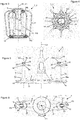
- the beater accessory 1 comprises a driving part 2 which comprises a body 3 more or less having a hollow bell shape, this body 3 being disposed along a first axis X1.
- the driving part is rotated along this first axis X1.
- the driving part 2 also comprises an arm 4 and another arm 5 which radially extend the body 3 in its lower part 3a, the arm 4 and the other arm 5 being arranged symmetrically with respect to each other, vis-à-vis the first axis X1.
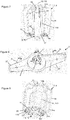
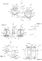
- the body 3 is hollow and comprises, in its internal part, coupling means formed by teeth 6, as illustrated by the two variants of the beater accessory 1 figures 2 and 11 . These teeth 6 are also illustrated on the figure 8 , for the first variant of the beater accessory 1.
- the beater accessory 1 is intended to be placed in a container of a device (not shown).
- the characteristics of such a device are well known to those skilled in the art, which is why they will not be detailed.
- the apparatus has traditionally comprises a body incorporating a rotation drive device, which comprises in particular a motor rotating a drive shaft, the drive shaft protruding from the upper part of the body.
- the apparatus also comprises a container, for example in the form of a bowl, which is adapted to be engaged on the upper part of the body, a position in which the drive shaft enters through the bottom of the container.
- This drive shaft comprises teeth complementary to the teeth 6 inside the body 3 of the beater accessory 1, so that the drive shaft meshes with the drive part 2 when the beater accessory 1 is placed in the container.
- the rotation of the motor then drives that of the driving part 2 along the first axis X1.
- a transmission shaft is arranged projecting in the bottom of the container, this transmission shaft being coupled to the drive shaft once the container in position on the body of the device.
- the transmission shaft comprises said teeth complementary to the teeth 6, inside the body 3 of the beater accessory 1.
- the beater accessory 1 also comprises a whip 7 and another whip 8, advantageously of identical design, which are mounted in rotation along two second axes X2, X3, respectively on the arm 4 and on the other arm 5.
- the second axes X2, X3 are parallel to the first axis X1 and arranged symmetrically with respect to each other along this first axis X1, as illustrated by FIGS. Figures 1, 2 , 10 and 11 .
- the driving part 2 comprises a shaft 9 and another shaft 10 which are respectively fixed on the arm 4 and on the other arm 5 and which extend upwards along the two second axes X 2, X 3, as shown in FIG. illustrate, for example, figures 5 and 13 for both variants of the beater accessory 1.
- the body 3, the arm 4 and the other arm 5 are formed of a one-piece element, while the shaft 9 and the other shaft 10 are attached to the arm 4 and the other arm 5. It is the same on the variant of Figures 10 to 14 . It is possible, however, to envisage variants for which the body 3, the arm 4 and the other arm 5 as well as the shaft 9 and the other shaft 10 are formed of a one-piece element.
- the whip 7 and the other whip 8 each comprise a hub 11, 110 which is rotatably mounted on the shaft 9 or on the other shaft 10 along the second axis X 2, X 3.
- the whip 7 and the other whip 8 also each comprise a base 12 and a head 13 respectively extending the lower ends 11a and 11b of the upper hub 11, 110.
- the base 12 is partially annular and is disposed above and away arm 4 or the other arm 5, as shown in particular by Figures 1 and 2 .
- Strands 14, for example eight in number, are uniformly distributed around the hub 11, 110, the lower ends 14a and 14b of these upper ends 14 being respectively assembled with the base 12 and with the head 13.
- the base 12 of the whip 7 or the other whip 8 comprises a cylindrical housing 17, a diameter slightly greater than that of the cylindrical studs 15, 16.
- each of the cylindrical studs 15, 16 forms a stop member arranged on the drive part 2 to block the translation of the hub 11 or the other hub 110 in a first direction along the second axis of rotation.
- the upper portions 9b, 10b of the shaft 9 and the other shaft 10 each comprise a groove 18 forming above it a head 19.
- Each head 19 comprises two helical grooves 20, 21 which open on the side lower 19a of said head 19, on the groove 18, and the upper side 19b of said head 19, on the upper end 9c, 10c of the shaft 9 or the other tree 10, as shown by the Figures 5 and 6 .
- the hub 11, 110 of the whip 7 or of the other whip 8 comprises on its inner cylindrical wall 22, at its upper end 11b, two studs 23, 24 arranged opposite each other, as shown by FIGS. Figures 3 and 4 .
- the whip 7 and the other whip 8 are held in position on the shaft 9 or the other shaft 10 by means of the aforementioned holding device (the studs 23, 24, the helical grooves 20, 21 on the head 19 and the groove 18), since only a determined manipulation consisting of pulling upwards and a slight rotation of the whip 7 or the other whip 8 until the studs 23, 24 correspond with the helical grooves 20, 21 on the lower side 19a of the head 19, allows to release the whip 7 or the other whip 8 of the shaft 9 or the other shaft 10.
- the drive part 2 rotates in the direction of the arrow F1, illustrated in figure 6 , which is the counterclockwise direction, which on the contrary tends to turn the whip 7 and the other whip 8 in the direction of the arrows F2, F3, illustrated in FIG.
- FIG. figure 6 which is clockwise, because of the effort exerted by the food preparation on the whip 7 or the other whip 8.
- the helical grooves 20, 21 on the heads 19 of the shaft 9 and the other shaft 10 each have a step to the right opposite the second axes X2, X3, as shown in FIG. figure 5 for the helical groove 20.
- the rotation of the whip 7 and the other whip 8, and therefore the pads 23, 24 on the hubs 11, 110 is made in such a way with respect to the right-hand grooves 20, 21, that said pads 23, 24 can not leave the grooves 18 on the shaft 9 and the other shaft 10, unless perform said determined manipulation above.
- the introduction of the whip 7 or the other whip 8 on the shaft 9 or on the other shaft 10 requires precise positioning of the studs 23, 24 opposite the helical grooves 20, 21, on the side upper 19b of the head 19, to allow the introduction of said pads 23, 24 in said helical grooves 20, 21 and their positioning in the groove 18 under the head 19.
- the upper portions 9b, 10b of the shaft 9 and the other shaft 10 each comprise a groove 18, as shown in FIG. figure 13 .
- This groove 18 receives an elastic washer 25, as illustrated by figure 12 .
- the hub 11, 110 of the whip 7 or the other whip 8 comprises on its inner cylindrical wall 22, at its upper end 11b, an internal groove 26.
- the spring washer 25 is compressed slightly, allowing its introduction and that of the shaft 9 or the other shaft 10 in the hub 11, 110.
- the spring washer 25 resumes its normal shape, which blocks the translation along the second axis X2, X3, whip 7 or the other whip 8 on the shaft 9 or on the Other shaft 10.
- the cylindrical studs 15, 16 are positioned in the cylindrical housings 17 of the bases 12 of the whips 7, 8.
- the whip 7 or the other whip 8 are held on the blank. 2.
- the holding device is configured to lock in translation, along the second axis X2 of rotation, the hub 11 mounted to rotate freely on the shaft 9, whatever the direction of rotation of the hub 11.
- the other holding device configured to block in translation, along the second axis X3 of rotation, the hub 110 mounted to rotate freely on the other shaft 10, whatever the direction of rotation of the hub 110.
- the arm 4 and the other arm 5 comprise scrapers 27, 28 each having a blade shape, the latter making it possible to scrape the bottom of the container during the rotation of the beater accessory 1.
- the scrapers 27, 28 are arranged upstream of the bases 12 of the whips 7, 8, with respect to the direction of rotation of the driving part 2 defined by the arrow F1 illustrated in FIG. figure 6 .
- the scrapers 27, 28 scrape the food preparation in the bottom of the container before said food preparation is mixed by the whip 7 and the other whip 8. This ensures that all the food preparation is properly stirred by the whip 7 and the other whip 8.
- the base 12 of the whip 7 and the other whip 8 comprises mixing means 120 comprising first corrugations 29 on the periphery of the base 12 and second undulations 30 on the lower face 12a of said base 12.
- These corrugations 29 On the partially annular base 12 are arranged above and at a distance from the arm 4 and the other arm 5.
- these corrugations 29, 30 ensure the mixing of the food preparation, including when a small amount of food preparation is disposed in the container of the apparatus, only the lower portion 14c of the strands 14 being immersed in the food preparation.
- These corrugations 29, 30 will be particularly effective when the height of the food preparation in the container does not exceed one fifth of the height of the whip 7 and the other whip 8.
- the preceding description of the two alternative embodiments of the beater accessory 1 according to the invention highlights the ease of assembly and disassembly of the whip 7 and the other whip 8 on the shaft 9 and the other shaft 10 of the invention.
- the drive part 2 the presence of a holding device ensuring the translation locking of the whip 7 and the other whip 8 on the shaft 9 and the other shaft 10 along the second axes X2, X3.
- the presence of the mixing means on the base 12 of the whisk 7 and the other whip 8 provides a brewing efficiency of small amounts of food preparations disposed in the container of the apparatus.
Landscapes
- Engineering & Computer Science (AREA)
- Mechanical Engineering (AREA)
- Food Science & Technology (AREA)
- Food-Manufacturing Devices (AREA)
Abstract
Description
- La présente invention concerne le domaine des appareils électroménagers de préparation culinaire et porte tout particulièrement sur un accessoire batteur utilisé sur un tel appareil pour permettre le brassage et l'émulsion des ingrédients composant la préparation culinaire, lesdits ingrédients étant versés dans un récipient dans lequel est disposé l'accessoire batteur.
- L'invention vise à concevoir un accessoire batteur facilement démontable et nettoyable.
- Un appareil électroménager de préparation culinaire comprend traditionnellement un corps qui réceptionne un récipient se présentant par exemple sous la forme d'un bol. Un moteur est agencé à l'intérieur du corps et entraîne en rotation un arbre d'entraînement. Cet arbre d'entraînement vient soit se loger en saillie dans le fond du récipient positionné sur ce corps, soit s'accoupler à un arbre de transmission disposé en saillie dans le fond du récipient.
- Un tel appareil électroménager comprend généralement plusieurs accessoires conçus chacun pour remplir une fonction et pour venir se loger dans le fond du récipient, en prise avec l'arbre d'entrainement ou avec l'arbre de transmission, la rotation de ce dernier permettant celle de l'accessoire.
- Parmi ces accessoires, l'un d'entre eux consiste en un accessoire batteur, conçu pour permettre le brassage et l'émulsion des ingrédients versés dans le récipient afin d'obtenir une préparation culinaire, par exemple une pâte à gâteau, une meringue, etc.
- Il est connu les titres suivants divulguant diverses mises en oeuvre d'un accessoire batteur présentant certaines caractéristiques comparables à celles objets de l'invention :
US2072691 ;GB667863 FR2282932A1 FR2773698B1 EP2326226B1 ;WO201180646A2 CN202277265U . L'accessoire batteur comprend une pièce d'entraînement munie d'un premier axe de rotation et un ou deux fouets montés libre en rotation sur la pièce d'entraînement selon un ou deux seconds axes de rotation excentrés par rapport au premier axe de rotation, grâce à des moyens de rotation agencés entre la pièce d'entraînement et le ou les fouets. Chaque fouet comprend des brins, voire des pales. L'excentration de l'axe secondaire du fouet et le frottement des brins avec les ingrédients durant la rotation de la pièce d'entraînement selon le premier axe de rotation permet audit fouet d'entrer en rotation selon le second axe de rotation, créant ainsi une trajectoire épicycloïdale des brins. Cette trajectoire implique une diminution des projections et une meilleure incorporation d'air durant le brassage des ingrédients. - Parmi ces titres précités, il est prévu dans la demande de brevet
WO201180646A2 WO201180646A2 - La présente invention a pour objectif de mettre en oeuvre une alternative d'accessoire batteur facilitant le démontage et le remontage du ou des fouets vis-à-vis de la pièce d'entraînement.
- A cet effet, l'invention concerne un accessoire batteur pour un appareil électroménager de préparation culinaire, cet accessoire batteur comprenant une pièce d'entraînement munie d'un premier axe de rotation et un fouet monté libre en rotation sur la pièce d'entraînement selon un second axe de rotation excentré par rapport au premier axe de rotation. Ce montage libre en rotation est mis en oeuvre grâce à des moyens de rotation agencés entre la pièce d'entraînement et le fouet.
- Selon l'invention, la pièce d'entraînement comprend un arbre s'étendant selon le second axe de rotation. En outre, le fouet comprend un moyeu monté libre en rotation sur l'arbre. Ce montage du moyeu sur l'arbre permet la mise en oeuvre des moyens de rotation entre le fouet et la pièce d'entraînement. En outre, l'accessoire batteur présente un dispositif de maintien configuré pour bloquer en translation, selon le second axe de rotation, le moyeu monté libre en rotation sur l'arbre, au moins lorsque le moyeu tourne selon un premier sens de rotation, et pour autoriser le retrait du fouet de l'arbre, et inversement la mise en place du fouet sur l'arbre, lorsque le fouet est manipulé d'une manière définie par rapport à l'arbre.
- Ainsi, au moins dans un premier sens de rotation le dispositif de maintien permet de bloquer la translation du moyeu engagé sur l'arbre, seule la rotation restant possible. Le montage du fouet sur la pièce d'entraînement est réalisé simplement en engageant le moyeu sur l'arbre, la mise en place du dispositif de maintien entre le moyeu et l'arbre suffisant à bloquer la translation entre ces deux éléments. Le démontage du fouet de la pièce d'entraînement, et inversement le montage du fouet sur la pièce d'entraînement, n'est rendu possible qu'en manipulant d'une manière définie ledit fouet par rapport à l'arbre. Ainsi, dans une première réalisation de l'invention, l'accessoire batteur peut comprendre un seul fouet et la pièce d'entraînement peut comprendre un seul arbre agencé selon un second axe de rotation, le moyeu du fouet étant engagé sur cet arbre et bloqué en translation selon le second axe grâce au dispositif de maintien.
- Selon une seconde réalisation, l'accessoire batteur comprend un autre fouet monté libre en rotation sur la pièce d'entraînement selon un autre second axe de rotation excentré par rapport au premier axe de rotation. En outre, la pièce d'entraînement comprend un autre arbre s'étendant selon l'autre second axe de rotation. L'autre fouet comprend un autre moyeu monté sur l'autre arbre. En outre, un autre dispositif de maintien est configuré pour bloquer en translation, selon l'autre second axe de rotation, l'autre moyeu monté libre en rotation sur l'autre arbre, au moins lorsque l'autre moyeu tourne selon un premier sens de rotation, et pour autoriser le retrait de l'autre fouet de l'autre arbre, et inversement la mise en place de l'autre fouet sur l'autre arbre, lorsque l'autre fouet est manipulé d'une manière définie par rapport à l'autre arbre.
- Ainsi, selon cette seconde réalisation, l'accessoire batteur comprend deux fouets (le fouet et l'autre fouet) comprenant chacun un moyeu, les deux fouets étant montés libres en rotation sur la pièce d'entraînement respectivement selon deux seconds axes de rotation distincts. En outre, la pièce d'entraînement comprend deux arbres fixes s'étendant respectivement selon les deux seconds axes de rotation. Les moyeux des fouets sont respectivement montés sur les arbres et bloqués en translation selon les seconds axes grâce à deux dispositifs de maintien.
- De préférence, selon cette seconde réalisation de l'accessoire batteur, le fouet et l'autre fouet sont disposés symétriquement l'un par rapport à l'autre, vis-à-vis du premier axe de rotation. On pourrait envisager une autre variante selon laquelle deux fouets seraient montés sur la pièce d'entraînement, chacun d'un côté vis-à-vis du premier axe de rotation, les deux seconds axes de rotation n'étant pas équidistants du premier axe de rotation. On pourrait aussi envisager une autre variante selon laquelle plusieurs fouets seraient montés sur la pièce d'entraînement, à distance et autour du premier axe de rotation. On pourrait aussi envisager une autre variante avec un seul fouet monté libre en rotation sur un seul bras de la pièce d'entraînement selon un second axe de rotation.
- Selon l'accessoire batteur objet de l'invention, la pièce d'entraînement comprend un corps agencé selon le premier axe de rotation et un bras s'étendant radialement vis-à-vis du corps, l'arbre s'étendant vers le haut sur le bras. Si désiré la pièce d'entraînement peut comprendre au moins un autre bras. Le ou un autre arbre s'étend alors sur le ou chaque autre bras. En la présence d'un seul fouet, un seul bras est prévu. En présence de deux fouets, deux bras sont disposés radialement vis-à-vis du corps et en opposition l'un par rapport à l'autre, deux arbres s'étendant vers le haut respectivement sur les deux bras. Selon la taille du récipient de travail utilisé, jusqu'à huit fouets pourraient être répartis autour du premier axe de rotation. Des réalisations comportant deux ou trois fouets sont toutefois préférées pour des questions de coût, d'efficacité de fonctionnement, et de simplicité de manipulation.
- Selon une première variante de conception de la pièce d'entraînement, l'arbre est rapporté sur le bras ; si désiré le ou chaque autre arbre est rapporté sur le ou l'un des autres bras. On peut toutefois envisager une seconde variante de conception de la pièce d'entraînement selon laquelle l'arbre, le corps et le bras, si désiré le ou les autre(s) arbre(s) et le ou les autre(s) bras sont formés d'un élément monobloc.
- Selon une conception de la pièce d'entraînement, le bras comprend un racloir. Ce racloir permet de décoller les ingrédients présents dans le fond du récipient. Si désiré le ou au moins l'un des autre(s) bras peut comprendre un racloir.
- Selon une conception de la pièce d'entraînement, le corps comprend une forme en cloche creuse s'étendant vers le haut selon le premier axe de rotation. Cette forme permet de saisir facilement l'accessoire batteur positionné dans le récipient.
- Selon une conception de la pièce d'entraînement, le corps comprend des moyens d'accouplement. Les moyens d'accouplement peuvent notamment être formés par des dents.
- Selon une première conception du dispositif de maintien, celui-ci comprend :
- un élément de butée agencé sur la pièce d'entraînement pour bloquer la translation du moyeu dans un premier sens selon le second axe de rotation,
- une gorge agencée sur l'arbre,
- une gorge interne agencée sur le moyeu,
- et une rondelle élastique s'engageant dans la gorge et formant un élément de blocage de la translation du moyeu dans un second sens selon ce second axe de rotation, une fois en position dans la gorge interne.
- Ainsi l'utilisateur peut dégager le fouet de la pièce d'entraînement en exerçant une traction selon la direction du second axe de rotation vers l'extrémité libre de l'arbre, et mettre en place le fouet sur la pièce d'entraînement avec un mouvement en sens inverse.
- Selon une seconde conception du dispositif de maintien, celui-ci comprend :
- une tête et une gorge agencées sur l'arbre, la gorge étant positionnée sous la tête, ladite tête comprenant au moins une rainure hélicoïdale débouchant d'un côté sur la gorge et de l'autre sur une extrémité supérieure de l'arbre,
- au moins un plot agencé à l'intérieur du moyeu et configuré pour pénétrer dans ladite au moins une rainure hélicoïdale et venir se loger dans la gorge lors de la mise en place du moyeu sur l'arbre.
- Ainsi l'utilisateur peut dégager le fouet de la pièce d'entraînement en engageant le ou les plots dans la ou les rainures hélicoïdales, selon le premier sens de rotation ; lorsque le fouet est tourné dans le second sens de rotation opposé au premier sens de rotation le fouet ne peut être dégagé de la pièce d'entraînement.
- De préférence, selon cette seconde conception du dispositif de maintien, celui-ci comprend deux rainures hélicoïdales et deux plots, les plots s'engageant respectivement dans les rainures hélicoïdales pour venir se loger dans la gorge.
- Ainsi, selon cette seconde conception du dispositif de maintien, seule une position particulière du moyeu vis-à-vis de l'arbre permet de monter ou de démonter le fouet de la pièce d'entraînement.
- Selon une conception de l'accessoire batteur, le fouet comprend des brins répartis autour du moyeu. Des variantes de conception sont envisageables en remplaçant les brins sur le fouet par des pales ou des ailettes. Si désiré le ou l'un au moins des autres fouets peut comprendre des brins répartis autour de l'autre moyeu.
- Selon une conception de l'accessoire batteur, dans une configuration selon laquelle la pièce d'entraînement comprend un corps et un bras, tel que précité, le moyeu comprend une base au moins partiellement annulaire munie de moyens de mélange évoluant au-dessus et à distance du bras recevant ledit moyeu, lors de la rotation dudit moyeu, pour favoriser le brassage et l'émulsion de faibles quantités de préparations alimentaires. Cela permet d'optimiser le travail du fouet avec des petites proportions de préparations alimentaires. On entend par faibles quantités de préparations alimentaires, des quantités de préparations alimentaires qui ne dépassent pas le cinquième de la hauteur du fouet lorsque l'accessoire batteur est en position dans le récipient. Si désiré, le ou les autres bras et le ou les autres moyeux peuvent présenter une configuration similaire.
- Selon une conception des moyens de mélange, ceux-ci sont constitués d'ondulations réparties autour et/ou en-dessous de la base.
- L'invention concerne également un appareil électroménager de préparation culinaire, lequel comprend un récipient muni d'un dispositif d'entraînement en rotation et un accessoire batteur présentant l'une et/ou l'autre des caractéristiques précitées. L'accessoire batteur est apte à être logé dans le récipient et accouplé avec le dispositif d'entraînement en rotation, selon le premier axe de rotation.
- L'invention concerne également un appareil électroménager de préparation culinaire comprenant un dispositif d'entraînement en rotation, un récipient de travail et un accessoire batteur apte à être entraîné en rotation dans le récipient de travail par le dispositif d'entraînement en rotation, du fait que l'accessoire batteur est conforme à l'une au moins des caractéristiques précitées et que l'accessoire batteur est apte à être entraîné en rotation dans le récipient de travail par le dispositif d'entraînement en rotation selon le premier axe de rotation.
- La description suivante met en évidence les caractéristiques et avantages de la présente invention. Cette description s'appuie sur des figures, parmi lesquelles :
- La
figure 1 illustre une vue d'ensemble d'un accessoire batteur selon un premier mode de conception ; - La
figure 2 illustre une vue de face, en coupe, de l'accessoire batteur de lafigure 1 ; - Les
figures 3 et 4 illustrent une conception du fouet selon ce premier mode de conception de l'accessoire batteur ; - Les
figures 5 et 6 illustrent une conception de la pièce d'entraînement selon ce premier mode de conception de l'accessoire batteur ; - La
figure 7 illustre en coupe le fouet positionné sur l'arbre de la pièce d'entraînement, selon ce premier mode de conception de l'accessoire batteur ; - La
figure 8 met en évidence des moyens d'accouplement sur la pièce d'entraînement ; - La
figure 9 met en évidence une base munie de moyens de mélange, sur le fouet ; - La
figure 10 illustre une vue d'ensemble d'un accessoire batteur selon un second mode de conception ; - La
figure 11 illustre une vue en coupe de face de l'accessoire batteur de lafigure 10 ; - La
figure 12 met en évidence la présence d'une rondelle élastique sur une gorge d'un arbre de la pièce d'entraînement selon le second mode de conception ; - La
figure 13 illustre la pièce d'entraînement selon ce second mode de conception de l'accessoire batteur ; - La
figure 14 illustre en coupe le fouet selon ce second mode de conception de l'accessoire batteur. - Dans la suite de la description, les mêmes références sont utilisées pour désigner les mêmes caractéristiques selon les diverses variantes de réalisation, sauf indication. En outre, le terme appareil est utilisé pour désigner un appareil électroménager de préparation culinaire qui est équipé d'un accessoire batteur selon l'invention.
- Sur les deux variantes illustrées en
figures 1 et10 , l'accessoire batteur 1 comprend une pièce d'entraînement 2 qui comporte un corps 3 présentant plus ou moins une forme de cloche creuse, ce corps 3 étant disposé selon un premier axe X1. La pièce d'entraînement est entraînée en rotation selon ce premier axe X1. La pièce d'entraînement 2 comporte également un bras 4 et un autre bras 5 qui prolongent radialement le corps 3 dans sa partie inférieure 3a, le bras 4 et l'autre bras 5 étant disposés symétriquement l'un par rapport à l'autre, vis-à-vis du premier axe X1. Le corps 3 est creux et comprend dans sa partie interne des moyens d'accouplement formés par des dents 6, comme l'illustrent les deux variantes de l'accessoire batteur 1 enfigures 2 et11 . Ces dents 6 sont également illustrées sur lafigure 8 , pour la première variante de l'accessoire batteur 1. - L'accessoire batteur 1 est destiné à être placé dans un récipient d'un appareil (non illustré). Les caractéristiques d'un tel appareil sont bien connues de l'homme du métier, raison pour laquelle elles ne seront pas détaillées. L'appareil comprend traditionnellement un corps qui incorpore un dispositif d'entraînement en rotation, lequel comporte notamment un moteur entraînant en rotation un arbre d'entraînement, cet arbre d'entraînement faisant saillie en partie supérieure du corps. L'appareil comprend également un récipient, par exemple sous la forme d'un bol, lequel est apte à être engagé sur la partie supérieure du corps, position dans laquelle l'arbre d'entraînement pénètre par le fond du récipient. Cet arbre d'entraînement comprend des dents complémentaires aux dents 6 à l'intérieur du corps 3 de l'accessoire batteur 1, de sorte que l'arbre d'entraînement engrène avec la pièce d'entraînement 2 lorsque l'accessoire batteur 1 est placé dans le récipient. La rotation du moteur entraîne alors celle de la pièce d'entraînement 2 selon le premier axe X1. On peut également envisager qu'un arbre de transmission soit agencé en saillie dans le fond du récipient, cet arbre de transmission étant accouplé à l'arbre d'entraînement une fois le récipient en position sur le corps de l'appareil. Dans ce cas, l'arbre de transmission comporte lesdites dents complémentaires aux dents 6, à l'intérieur du corps 3 de l'accessoire batteur 1.
- L'accessoire batteur 1 comprend également un fouet 7 et un autre fouet 8, avantageusement de conception identique, qui sont montés en rotation selon deux seconds axes X2, X3, respectivement sur le bras 4 et sur l'autre bras 5. Les seconds axes X2, X3 sont parallèles au premier axe X1 et disposés symétriquement l'un vis-à-vis de l'autre selon ce premier axe X1, comme l'illustrent les
figures 1, 2 ,10 et 11 . La pièce d'entraînement 2 comprend un arbre 9 et un autre arbre 10 qui sont fixés respectivement sur le bras 4 et sur l'autre bras 5 et qui s'étendent vers le haut, selon les deux seconds axes X2, X3, comme l'illustrent par exemple lesfigures 5 et13 pour les deux variantes de l'accessoire batteur 1. Sur la variante desfigures 1 à 9 , le corps 3, le bras 4 et l'autre bras 5 sont formés d'un élément monobloc, tandis que l'arbre 9 et l'autre arbre 10 sont rapportés sur le bras 4 et sur l'autre bras 5. Il en est de même sur la variante desfigures 10 à 14 . On peut toutefois envisager des variantes pour lesquelles le corps 3, le bras 4 et l'autre bras 5 ainsi que l'arbre 9 et l'autre arbre 10 sont formés d'un élément monobloc. - Comme l'illustrent par exemple les
figures 2 ,3 ,11 et 14 , le fouet 7 et l'autre fouet 8 comprennent chacun un moyeu 11, 110 qui est monté en rotation sur l'arbre 9 ou sur l'autre arbre 10 selon le second axe X2, X3. Le fouet 7 et l'autre fouet 8 comprennent chacun également une base 12 et une tête 13 prolongeant respectivement les extrémités inférieure 11a et supérieure 11b du moyeu 11, 110. La base 12 est partiellement annulaire et elle est disposée au-dessus et à distance du bras 4 ou de l'autre bras 5, comme le montrent notamment lesfigures 1 et 2 . Des brins 14, par exemple au nombre de huit, sont uniformément répartis autour du moyeu 11, 110, les extrémités inférieure 14a et supérieure 14b de ces brins 14 étant respectivement assemblées avec la base 12 et avec la tête 13. - Comme l'illustrent par exemple les
figures 5 et13 , deux plots cylindriques 15, 16 sont agencés respectivement sur le bras 4 ou sur l'autre bras 5, selon les seconds axes X2, X3, ces plots cylindriques 15, 16 constituant des épaulements aux extrémités inférieures 9a, 10a de l'arbre 9 et de l'autre arbre 10. Comme l'illustrent par exemple lesfigures 3 et14 , la base 12 du fouet 7 ou de l'autre fouet 8 comprend un logement cylindrique 17, d'un diamètre légèrement supérieur à celui des plots cylindriques 15, 16. Lorsque les moyeux 11, 110 du fouet 7 et de l'autre fouet 8 sont engagés respectivement sur l'arbre 9 et sur l'autre arbre 10, les logements cylindriques 17 réceptionnent les plots cylindriques 15, 16 et viennent en butée sur ceux-ci, ce qui limite la translation vers le bas, selon les seconds axes X2, X3, du fouet 7 et de l'autre fouet 8 vis-à-vis de la pièce d'entraînement 2. Ainsi chacun des plots cylindriques 15, 16 forme un élément de butée agencé sur la pièce d'entraînement 2 pour bloquer la translation du moyeu 11 ou de l'autre moyeu 110 dans un premier sens selon le second axe de rotation. - Sur la variante des
figures 1 à 9 , les parties supérieures 9b, 10b de l'arbre 9 et de l'autre arbre 10 comprennent chacune une gorge 18 formant au-dessus de celle-ci une tête 19. Chaque tête 19 comprend deux rainures hélicoïdales 20, 21 qui débouchent du côté inférieur 19a de ladite tête 19, sur la gorge 18, et du côté supérieur 19b de ladite tête 19, sur l'extrémité supérieure 9c, 10c de l'arbre 9 ou de l'autre arbre 10, comme le montrent lesfigures 5 et 6 . Le moyeux 11, 110 du fouet 7 ou de l'autre fouet 8 comprend sur sa paroi cylindrique interne 22, au niveau de son extrémité supérieure 11b, deux plots 23, 24 disposés en vis-à-vis, comme le montrent lesfigures 3 et 4 . Lors de la mise en place du fouet 7 ou de l'autre fouet 8 sur l'arbre 9 ou sur l'autre arbre 10, seule une position angulaire définie permet d'engager les plots 23, 24 respectivement dans les deux rainures hélicoïdales 20, 21, par le côté supérieur 19b de la tête 19. Une légère rotation du fouet 7 ou de l'autre fouet 8 permet ensuite aux plots 23, 24 de descendre dans les rainures hélicoïdales 20, 21 jusqu'à atteindre le côté inférieur 19a de la tête 19 et venir se loger dans la gorge 18, comme l'illustre lafigure 7 . Une fois la gorge 18 atteinte, le fouet 7 ou l'autre fouet 8 peut tourner librement autour de l'arbre 9 ou de l'autre arbre 10 selon le second axe X2, X3. - Le fouet 7 et l'autre fouet 8 sont maintenus en position sur l'arbre 9 ou l'autre arbre 10 grâce à ce dispositif de maintien précité (les plots 23, 24, les rainures hélicoïdales 20, 21 sur la tête 19 et la gorge 18), puisque seule une manipulation déterminée consistant à effectuer une traction vers le haut et une légère rotation du fouet 7 ou de l'autre fouet 8 jusqu'à ce que les plots 23, 24 correspondent avec les rainures hélicoïdales 20, 21 sur le côté inférieur 19a de la tête 19, permet de dégager le fouet 7 ou l'autre fouet 8 de l'arbre 9 ou de l'autre arbre 10. En effet, la pièce d'entraînement 2 tourne dans le sens de la flèche F1, illustrée en
figure 6 , qui est le sens antihoraire, ce qui tend au contraire à faire tourner le fouet 7 et l'autre fouet 8 dans les sens des flèches F2, F3, illustrées enfigure 6 , qui est le sens horaire, du fait de l'effort exercé par la préparation alimentaire sur le fouet 7 ou l'autre fouet 8. Les rainures hélicoïdales 20, 21 sur les têtes 19 de l'arbre 9 et de l'autre arbre 10 présentent chacune un pas à droite en regard des seconds axes X2, X3, comme le montre lafigure 5 pour la rainure hélicoïdale 20. Ainsi la rotation du fouet 7 et de l'autre fouet 8, et donc des plots 23, 24 sur les moyeux 11, 110, s'effectue d'une telle manière par rapport au pas à droite des rainures hélicoïdales 20, 21, que lesdits plots 23, 24 ne peuvent pas sortir des gorges 18 sur l'arbre 9 et l'autre arbre 10, à moins d'effectuer ladite manipulation déterminée précitée. On comprend, qu'inversement, la mise en place du fouet 7 ou de l'autre fouet 8 sur l'arbre 9 ou sur l'autre arbre 10 nécessite de positionner précisément les plots 23, 24 en regard des rainures hélicoïdales 20, 21, du côté supérieur 19b de la tête 19, afin de permettre l'introduction desdits plots 23, 24 dans lesdites rainures hélicoïdales 20, 21 et leur positionnement dans la gorge 18 sous la tête 19. - Sur la variante des
figures 10 à 14 , les parties supérieures 9b, 10b de l'arbre 9 et l'autre arbre 10 comprennent chacune une gorge 18, comme l'illustre lafigure 13 . Cette gorge 18 reçoit une rondelle élastique 25, comme l'illustre lafigure 12 . Le moyeu 11, 110 du fouet 7 ou de l'autre fouet 8 comprend sur sa paroi cylindrique interne 22, au niveau de son extrémité supérieure 11b, une gorge interne 26. Lorsque le fouet 7 ou l'autre fouet 8 est engagé sur l'arbre 9 ou l'autre arbre 10, la rondelle élastique 25 se comprime légèrement, ce qui permet son introduction et celle de l'arbre 9 ou de l'autre arbre 10 dans le moyeu 11, 110. Une fois que la rondelle élastique 25 atteint la position de la gorge interne 26, cette rondelle élastique 25 reprend sa forme normale, ce qui bloque la translation selon le second axe X2, X3, du fouet 7 ou de l'autre fouet 8 sur l'arbre 9 ou sur l'autre arbre 10. Dans cette position, les plots cylindriques 15, 16 sont positionnés dans les logements cylindriques 17 des bases 12 des fouets 7, 8. Dans cette position, le fouet 7 ou l'autre fouet 8 sont maintenus sur la pièce d'entrainement 2. Une traction vers le haut, selon la direction du second axe X2, X3 de rotation, permet de comprimer légèrement la rondelle élastique 25 pour dégager le moyeu 11, 110 de l'arbre 9 ou de l'autre arbre 10 et extraire le fouet 7 ou l'autre fouet 8. Ainsi, seule une manipulation déterminée consistant à tirer vers le haut le fouet 7, 8 permet de dégager le moyeu 11, 110 de l'arbre 9 ou de l'autre arbre 10. Inversement, une poussée vers le bas du fouet 7 ou de l'autre fouet 8 permet d'engager le moyeu 11, 110 sur l'arbre 9 ou sur l'autre arbre 10. Ainsi le dispositif de maintien est configuré pour bloquer en translation, selon le second axe X2 de rotation, le moyeu 11 monté libre en rotation sur l'arbre 9, quel que soit le sens de rotation du moyeu 11. Il en va de même pour l'autre dispositif de maintien configuré pour bloquer en translation, selon le second axe X3 de rotation, le moyeu 110 monté libre en rotation sur l'autre arbre 10, quel que soit le sens de rotation du moyeu 110. - Comme l'illustrent par exemple les
figures 5, 6 ,10 et 13 , le bras 4 et l'autre bras 5 comprennent des racloirs 27, 28 ayant chacun une forme de lame, ceux-ci permettant de racler le fond du récipient durant la rotation de l'accessoire batteur 1. Les racloirs 27, 28 sont disposés en amont des bases 12 des fouets 7, 8, par rapport au sens de rotation de la pièce d'entraînement 2 défini par la flèche F1 illustrée enfigure 6 . Ainsi, les racloirs 27, 28 raclent la préparation alimentaire dans le fond du récipient avant que ladite préparation alimentaire soit mélangée par le fouet 7 et l'autre fouet 8. On garantit ainsi que toute la préparation alimentaire est convenablement brassée par le fouet 7 et l'autre fouet 8. - Comme l'illustrent les
figures 4 et9 , la base 12 du fouet 7 et de l'autre fouet 8 comprend des moyens de mélange 120 comportant des premières ondulations 29 sur la périphérie de la base 12 et des secondes ondulations 30 sur la face inférieure 12a de ladite base 12. Ces ondulations 29, 30 sur la base 12 partiellement annulaire sont disposées au-dessus et à distance du bras 4 et de l'autre bras 5. Lors de la rotation du fouet 7 et de l'autre fouet 8, ces ondulations 29, 30 assurent le mélange de la préparation alimentaire, y compris lorsqu'une faible quantité de préparation alimentaire est disposée dans le récipient de l'appareil, seule la partie inférieure 14c des brins 14 étant plongée dans la préparation alimentaire. Ces ondulations 29, 30 seront tout particulièrement efficaces lorsque la hauteur de préparation alimentaire dans le récipient n'excède pas le cinquième de la hauteur du fouet 7 et de l'autre fouet 8. On peut envisager de telles ondulations sur la base 12 du fouet 7 et de l'autre fouet 8 de la variante desfigures 10 à 14 . On peut aussi remplacer ces ondulations 29, 30 sur la base 12 du fouet 7 et de l'autre fouet 8 par d'autres moyens de mélange 120, par exemple des pales ou des ailettes agencées autour et/ou en-dessous de ladite base 12. - La description précédente des deux variantes de réalisation de l'accessoire batteur 1 selon l'invention met en exergue la facilité de montage et de démontage du fouet 7 et de l'autre fouet 8 sur l'arbre 9 et l'autre arbre 10 de la pièce d'entraînement 2, la présence d'un dispositif de maintien assurant le blocage en translation du fouet 7 et de l'autre fouet 8 sur l'arbre 9 et l'autre arbre 10 selon les seconds axes X2, X3.
- La présence des moyens de mélange sur la base 12 du fouet 7 et de l'autre fouet 8 offre une efficacité de brassage de faibles quantités de préparations alimentaires disposées dans le récipient de l'appareil.
- Bien entendu, des variantes de réalisation restent envisageables sans sortir du cadre de l'invention. On peut notamment prévoir un seul fouet 7 sur l'accessoire batteur 1. On peut aussi prévoir le fouet 7 et l'autre fouet 8 sur l'accessoire batteur 1, mais en disposant les seconds axes X2, X3 à des distances différentes vis-à-vis du premier axe X1. On peut aussi prévoir au moins un fouet additionnel sur l'accessoire batteur 1 en complément du fouet 7 et de l'autre fouet 8, avantageusement monté libre en rotation sur la pièce d'entraînement 2 selon un axe de rotation additionnel distinct, si désiré sur un bras additionnel de la pièce d'entraînement 2. On peut aussi prévoir de remplacer les brins 14 sur le fouet 7 ou le ou l'un au moins des autres fouets 8 par des pales ou des ailettes.
Claims (16)
- Accessoire batteur (1) pour un appareil électroménager de préparation culinaire, ledit accessoire batteur (1) comprenant une pièce d'entraînement (2) munie d'un premier axe (X1) de rotation et un fouet (7) monté libre en rotation sur la pièce d'entraînement (2) selon un second axe (X2) de rotation excentré par rapport au premier axe (X1) de rotation, caractérisé en ce que la pièce d'entraînement (2) comprend un arbre (9) s'étendant selon le second axe (X2) de rotation, en ce que le fouet (7) comprend un moyeu (11) monté libre en rotation sur l'arbre (9), et en ce que l'accessoire batteur (1) présente un dispositif de maintien configuré pour bloquer en translation, selon le second axe (X2) de rotation, le moyeu (11) monté libre en rotation sur l'arbre (9), au moins lorsque le moyeu (11) tourne selon un premier sens de rotation, et pour autoriser le retrait du fouet (7) de l'arbre (9), et inversement la mise en place du fouet (7) sur l'arbre (9), lorsque le fouet (7) est manipulé d'une manière définie par rapport à l'arbre (9).
- Accessoire batteur (1) selon la revendication 1, caractérisé en ce qu'il comprend un autre fouet (8) monté libre en rotation sur la pièce d'entraînement (2) selon un autre second axe (X3) de rotation excentré par rapport au premier axe (X1) de rotation, la pièce d'entraînement (2) comprenant un autre arbre (10) s'étendant selon l'autre second axe (X3) de rotation, l'autre fouet (8) comprend un autre moyeu (110) monté sur l'autre arbre (10), et en ce qu'un autre dispositif de maintien est configuré pour bloquer en translation, selon l'autre second axe (X3) de rotation, l'autre moyeu (110) monté libre en rotation sur l'autre arbre (10), au moins lorsque l'autre moyeu (110) tourne selon un premier sens de rotation, et pour autoriser le retrait de l'autre fouet (8) de l'autre arbre (10), et inversement la mise en place de l'autre fouet (8) sur l'autre arbre (10), lorsque l'autre fouet (8) est manipulé d'une manière définie par rapport à l'autre arbre (10).
- Accessoire batteur (1) selon la revendication 2, caractérisé en ce que le fouet (7) et l'autre fouet (8) sont disposés symétriquement l'un par rapport à l'autre, vis-à-vis du premier axe (X1) de rotation.
- Accessoire batteur (1) selon l'une des revendications 1 à 3, caractérisé en ce que la pièce d'entraînement (2) comprend un corps (3) agencé selon le premier axe (X1) de rotation et un bras (4) s'étendant radialement vis-à-vis du corps (3), et en ce que l'arbre (9) s'étend vers le haut sur le bras (4).
- Accessoire batteur (1) selon la revendication 4, caractérisé en ce que l'arbre (9) est rapporté sur le bras (4).
- Accessoire batteur (1) selon la revendication 4, caractérisé en ce que l'arbre (9), le corps (3) et le bras (4) sont formés d'un élément monobloc.
- Accessoire batteur (1) selon l'une des revendications 4 à 6, caractérisé en ce que le bras (4) comprend un racloir (27).
- Accessoire batteur (1) selon l'une des revendications 4 à 7, caractérisé en ce que le corps (3) comprend une forme en cloche creuse s'étendant vers le haut selon le premier axe (X1) de rotation.
- Accessoire batteur (1) selon l'une des revendications 4 à 8, caractérisé en ce que le corps (3) comprend des moyens d'accouplement.
- Accessoire batteur (1) selon l'une des revendications 1 à 9, caractérisé en ce que le dispositif de maintien comprend :- un élément de butée agencé sur la pièce d'entraînement (2) pour bloquer la translation du moyeu (11) dans un premier sens selon le second axe (X2) de rotation,- une gorge (18) agencée sur l'arbre (9),- une gorge interne (26) agencée sur le moyeu (11),- et une rondelle élastique (25) s'engageant dans la gorge (18) et formant un élément de blocage de la translation du moyeu (11) dans un second sens selon ce second axe (X2) de rotation, une fois en position dans la gorge interne (26).
- Accessoire batteur (1) selon l'une des revendications 1 à 9, caractérisé en ce que le dispositif de maintien comprend :- une tête (19) et une gorge (18) agencées sur l'arbre (9), la gorge (18) étant positionnée sous la tête (19), ladite tête (19) comprenant au moins une rainure hélicoïdale (20) débouchant d'un côté sur la gorge (18) et de l'autre sur une extrémité supérieure (9c) de l'arbre (9),- au moins un plot (23) agencé à l'intérieur du moyeu (11) et configuré pour pénétrer dans ladite au moins une rainure hélicoïdale (20) et venir se loger dans la gorge (18) lors de la mise en place du moyeu (11) sur l'arbre (9).
- Accessoire batteur (1) selon la revendication 11, caractérisé en ce que le dispositif de maintien comprend deux rainures hélicoïdales (20, 21) et deux plots (23, 24), les plots (23, 24) s'engageant respectivement dans les rainures hélicoïdales (20, 21) pour venir se loger dans la gorge (18).
- Accessoire batteur (1) selon l'une des revendications 1 à 12, caractérisé en ce que le fouet (7) comprend des brins (14) répartis autour du moyeu (11).
- Accessoire batteur (1) selon l'une des revendications 4 à 13, rattachée à la revendication 4, caractérisé en ce que le moyeu (11) comprend une base (12) au moins partiellement annulaire munie de moyens de mélange (120) évoluant au-dessus et à distance du bras (4) recevant ledit moyeu (11), lors de la rotation dudit moyeu (11), pour favoriser le brassage et l'émulsion de faibles quantités de préparations alimentaires.
- Accessoire batteur (1) selon la revendication 14, caractérisé en ce que les moyens de mélange sont constitués d'ondulations (29, 30) réparties autour et/ou en-dessous de la base (12).
- Appareil électroménager de préparation culinaire comprenant un dispositif d'entraînement en rotation, un récipient de travail et un accessoire batteur (1) apte à être entraîné en rotation dans le récipient de travail par le dispositif d'entraînement en rotation, caractérisé en ce que l'accessoire batteur (1) est conforme à l'une au moins des revendications 1 à 4, 5 ou 6, 7 à 9, 10 ou 11, 12 à 15 et en ce que l'accessoire batteur (1) est apte à être entraîné en rotation dans le récipient de travail par le dispositif d'entraînement en rotation selon le premier axe (X1) de rotation.
Applications Claiming Priority (1)
| Application Number | Priority Date | Filing Date | Title |
|---|---|---|---|
| FR1852565A FR3079125B1 (fr) | 2018-03-23 | 2018-03-23 | Accessoire batteur pour un appareil electromenager de preparation culinaire, equipe de fouet(s) facilement demontable(s) |
Publications (2)
| Publication Number | Publication Date |
|---|---|
| EP3542689A1 true EP3542689A1 (fr) | 2019-09-25 |
| EP3542689B1 EP3542689B1 (fr) | 2026-05-13 |
Family
ID=62684882
Family Applications (1)
| Application Number | Title | Priority Date | Filing Date |
|---|---|---|---|
| EP19161735.6A Active EP3542689B1 (fr) | 2018-03-23 | 2019-03-08 | Accessoire batteur pour un appareil électroménager de préparation culinaire, equipé de fouet(s) facilement démontable(s) |
Country Status (3)
| Country | Link |
|---|---|
| EP (1) | EP3542689B1 (fr) |
| CN (2) | CN210330373U (fr) |
| FR (1) | FR3079125B1 (fr) |
Cited By (4)
| Publication number | Priority date | Publication date | Assignee | Title |
|---|---|---|---|---|
| CN110833087A (zh) * | 2019-10-31 | 2020-02-25 | 苏州法兰卡食品有限公司 | 一种马卡龙制作方法以及高效打蛋器 |
| CN112426050A (zh) * | 2020-10-30 | 2021-03-02 | 添可智能科技有限公司 | 用于厨房机器人的锅铲组件及厨房机器人 |
| CN114365941A (zh) * | 2020-10-15 | 2022-04-19 | 苏州西顿家用自动化有限公司 | 一种炒饭用锅铲及其驱动机构以及使用该锅铲的炒饭设备 |
| CN118320662A (zh) * | 2024-06-12 | 2024-07-12 | 杭州美科光电科技有限公司 | 一种led封装胶水的混合搅拌装置及其方法 |
Families Citing this family (2)
| Publication number | Priority date | Publication date | Assignee | Title |
|---|---|---|---|---|
| FR3079125B1 (fr) * | 2018-03-23 | 2023-01-20 | Seb Sa | Accessoire batteur pour un appareil electromenager de preparation culinaire, equipe de fouet(s) facilement demontable(s) |
| CN112274030A (zh) * | 2020-10-30 | 2021-01-29 | 添可智能科技有限公司 | 厨房机器人及其锅铲组件 |
Citations (11)
| Publication number | Priority date | Publication date | Assignee | Title |
|---|---|---|---|---|
| US2072691A (en) | 1933-12-26 | 1937-03-02 | Hobart Mfg Co | Aerating apparatus |
| GB667863A (en) | 1950-01-24 | 1952-03-12 | Knud Viktor Hansen Christiense | Kneading or mixing member for use in mixing machines |
| DE1196164B (de) * | 1963-07-20 | 1965-07-08 | Dierks & Soehne | Schlagmischer zur Herstellung schaumartiger Massen |
| FR2282932A1 (fr) | 1974-08-26 | 1976-03-26 | Kimmel Hans | Outil agitateur pour un melangeur ou un agitateur |
| WO1986003112A1 (fr) * | 1984-11-21 | 1986-06-05 | Göran Persson Maskin Ab | Dispositif pour battre et melanger liquides et pates lisses |
| FR2773698B1 (fr) | 1998-01-22 | 2000-05-12 | Ronic Ind | Dispositif a fouet pour appareil de preparation culinaire |
| DE202009006852U1 (de) * | 2008-05-30 | 2009-08-20 | Koninklijke Philips Electronics N.V. | Mixersystem mit einem Messergebilde |
| EP2326226A2 (fr) | 2008-07-02 | 2011-06-01 | BSH Bosch und Siemens Hausgeräte GmbH | Agitateur, en particulier pour appareil ménager |
| WO2011080646A2 (fr) | 2009-12-28 | 2011-07-07 | Koninklijke Philips Electronics N.V. | Ensemble de batteur et appareil de cuisine comprenant un ensemble de batteur |
| CN202277265U (zh) | 2011-09-16 | 2012-06-20 | 邓志明 | 三轴搅拌机 |
| GB2519805A (en) * | 2013-10-31 | 2015-05-06 | Kenwood Ltd | Food-processing tools and food-processing appliances incorporating same |
Family Cites Families (7)
| Publication number | Priority date | Publication date | Assignee | Title |
|---|---|---|---|---|
| CH612725A5 (en) * | 1977-08-02 | 1979-08-15 | Mekafor | Hammer drill |
| JP4233158B2 (ja) * | 1998-11-04 | 2009-03-04 | 本田技研工業株式会社 | 締付装置 |
| FR3009942B1 (fr) * | 2013-08-29 | 2015-09-25 | Seb Sa | Appareil electromenager de preparation culinaire comportant un outil de travail venant s'engager de maniere amovible sur un entraineur |
| CN106466575A (zh) * | 2015-08-17 | 2017-03-01 | 上海弗鲁克科技发展有限公司 | 搅拌系统及行星轮式搅拌器 |
| CN106669526A (zh) * | 2015-11-06 | 2017-05-17 | 尤世元 | 一种轮式搅拌器的制备 |
| GB2544967A (en) * | 2015-11-25 | 2017-06-07 | Kenwood Ltd | Stirring tool |
| FR3079125B1 (fr) * | 2018-03-23 | 2023-01-20 | Seb Sa | Accessoire batteur pour un appareil electromenager de preparation culinaire, equipe de fouet(s) facilement demontable(s) |
-
2018
- 2018-03-23 FR FR1852565A patent/FR3079125B1/fr active Active
-
2019
- 2019-03-08 EP EP19161735.6A patent/EP3542689B1/fr active Active
- 2019-03-22 CN CN201920372631.4U patent/CN210330373U/zh not_active Withdrawn - After Issue
- 2019-03-22 CN CN201910225023.5A patent/CN110292320B/zh active Active
Patent Citations (11)
| Publication number | Priority date | Publication date | Assignee | Title |
|---|---|---|---|---|
| US2072691A (en) | 1933-12-26 | 1937-03-02 | Hobart Mfg Co | Aerating apparatus |
| GB667863A (en) | 1950-01-24 | 1952-03-12 | Knud Viktor Hansen Christiense | Kneading or mixing member for use in mixing machines |
| DE1196164B (de) * | 1963-07-20 | 1965-07-08 | Dierks & Soehne | Schlagmischer zur Herstellung schaumartiger Massen |
| FR2282932A1 (fr) | 1974-08-26 | 1976-03-26 | Kimmel Hans | Outil agitateur pour un melangeur ou un agitateur |
| WO1986003112A1 (fr) * | 1984-11-21 | 1986-06-05 | Göran Persson Maskin Ab | Dispositif pour battre et melanger liquides et pates lisses |
| FR2773698B1 (fr) | 1998-01-22 | 2000-05-12 | Ronic Ind | Dispositif a fouet pour appareil de preparation culinaire |
| DE202009006852U1 (de) * | 2008-05-30 | 2009-08-20 | Koninklijke Philips Electronics N.V. | Mixersystem mit einem Messergebilde |
| EP2326226A2 (fr) | 2008-07-02 | 2011-06-01 | BSH Bosch und Siemens Hausgeräte GmbH | Agitateur, en particulier pour appareil ménager |
| WO2011080646A2 (fr) | 2009-12-28 | 2011-07-07 | Koninklijke Philips Electronics N.V. | Ensemble de batteur et appareil de cuisine comprenant un ensemble de batteur |
| CN202277265U (zh) | 2011-09-16 | 2012-06-20 | 邓志明 | 三轴搅拌机 |
| GB2519805A (en) * | 2013-10-31 | 2015-05-06 | Kenwood Ltd | Food-processing tools and food-processing appliances incorporating same |
Cited By (4)
| Publication number | Priority date | Publication date | Assignee | Title |
|---|---|---|---|---|
| CN110833087A (zh) * | 2019-10-31 | 2020-02-25 | 苏州法兰卡食品有限公司 | 一种马卡龙制作方法以及高效打蛋器 |
| CN114365941A (zh) * | 2020-10-15 | 2022-04-19 | 苏州西顿家用自动化有限公司 | 一种炒饭用锅铲及其驱动机构以及使用该锅铲的炒饭设备 |
| CN112426050A (zh) * | 2020-10-30 | 2021-03-02 | 添可智能科技有限公司 | 用于厨房机器人的锅铲组件及厨房机器人 |
| CN118320662A (zh) * | 2024-06-12 | 2024-07-12 | 杭州美科光电科技有限公司 | 一种led封装胶水的混合搅拌装置及其方法 |
Also Published As
| Publication number | Publication date |
|---|---|
| FR3079125B1 (fr) | 2023-01-20 |
| CN110292320A (zh) | 2019-10-01 |
| EP3542689B1 (fr) | 2026-05-13 |
| CN110292320B (zh) | 2024-09-10 |
| FR3079125A1 (fr) | 2019-09-27 |
| CN210330373U (zh) | 2020-04-17 |
Similar Documents
| Publication | Publication Date | Title |
|---|---|---|
| EP3542689B1 (fr) | Accessoire batteur pour un appareil électroménager de préparation culinaire, equipé de fouet(s) facilement démontable(s) | |
| EP3542688B1 (fr) | Accessoire batteur pour un appareil électroménager de préparation culinaire, adapté au melange de faibles quantités de préparation alimentaire | |
| EP3624657B1 (fr) | Appareil de mixage et de melange pour des preparations alimentaires liquides ou pateuses equipe d'un dispositif de verrouillage des couteaux sur le bol | |
| EP2159015B1 (fr) | Appareil électroménager de découpe d'aliments en continu avec montage d'outil simplifié | |
| FR2666214A1 (fr) | Ensemble de cuisson a micro-ondes. | |
| EP3219229B1 (fr) | Vis et appareil de pressage d'aliments de type fruits et/ou légumes équipé d'un système de balayage | |
| EP2892405B1 (fr) | Appareil de préparation culinaire comportant un crochet de petrissage entraîné selon un mouvement planétaire | |
| EP3188631B1 (fr) | Dispositif de préparation d'aliments adapté au travail des aliments cuits et/ou friables | |
| WO2015033055A1 (fr) | Dispositif de preparation d'aliments pour extraire des jus et/ou des coulis | |
| CA2864361C (fr) | Dispositif d'entrainement d'un outil rotatif pour appareil de traitement alimentaire, et appareil de traitement alimentaire pourvu d'un tel dispositif d'entrainement | |
| EP2026687B1 (fr) | Recipient de traitement thermique d'aliments | |
| EP1017302B1 (fr) | Appareil electromenager de preparation culinaire, du genre robot menager multi-usages, comportant un ensemble de travail rotatif associe a un moyen d'appui | |
| FR3010296A1 (fr) | Dispositif de preparation d’aliments pour extraire des jus et/ou des coulis et controler leur ecoulement | |
| EP3550988B1 (fr) | Dispositif pour la realisation de preparations alimentaires glacees et appareil equipe d'un tel dispositif | |
| FR3125404A3 (fr) | Dispositif de coupe pour un ustensile de cuisine | |
| CA3235532A1 (fr) | Appareil culinaire avec dispositif d'entrainement a corde a commande amovible | |
| EP3708044B1 (fr) | Kit d'éléments d'assemblage d'une cuve d'appareil de cuisson du type friteuse à air chaud | |
| EP3053499B1 (fr) | Batteur-melangeur comportant un outil crochet | |
| EP4285797B1 (fr) | Appareil de cuisson d'aliments comprenant une première cuve de cuisson amovible et une deuxième cuve de cuisson amovible | |
| FR3150411A3 (fr) | Organe de travail rotatif pour dispositif de preparation culinaire | |
| EP0925751A1 (fr) | Accessoire de tournebroche pour la cuisson des aliments | |
| WO2016009163A1 (fr) | Outil de travail rotatif réversible et dispositif de préparation d'aliments comportant un outil de travail rotatif réversible | |
| EP3939481A1 (fr) | Systeme de verrouillage d'un bol sur une base motorisee d'un robot culinaire |
Legal Events
| Date | Code | Title | Description |
|---|---|---|---|
| PUAI | Public reference made under article 153(3) epc to a published international application that has entered the european phase |
Free format text: ORIGINAL CODE: 0009012 |
|
| STAA | Information on the status of an ep patent application or granted ep patent |
Free format text: STATUS: THE APPLICATION HAS BEEN PUBLISHED |
|
| AK | Designated contracting states |
Kind code of ref document: A1 Designated state(s): AL AT BE BG CH CY CZ DE DK EE ES FI FR GB GR HR HU IE IS IT LI LT LU LV MC MK MT NL NO PL PT RO RS SE SI SK SM TR |
|
| AX | Request for extension of the european patent |
Extension state: BA ME |
|
| STAA | Information on the status of an ep patent application or granted ep patent |
Free format text: STATUS: REQUEST FOR EXAMINATION WAS MADE |
|
| 17P | Request for examination filed |
Effective date: 20200324 |
|
| RBV | Designated contracting states (corrected) |
Designated state(s): AL AT BE BG CH CY CZ DE DK EE ES FI FR GB GR HR HU IE IS IT LI LT LU LV MC MK MT NL NO PL PT RO RS SE SI SK SM TR |
|
| STAA | Information on the status of an ep patent application or granted ep patent |
Free format text: STATUS: EXAMINATION IS IN PROGRESS |
|
| 17Q | First examination report despatched |
Effective date: 20221020 |
|
| GRAP | Despatch of communication of intention to grant a patent |
Free format text: ORIGINAL CODE: EPIDOSNIGR1 |
|
| STAA | Information on the status of an ep patent application or granted ep patent |
Free format text: STATUS: GRANT OF PATENT IS INTENDED |
|
| RIC1 | Information provided on ipc code assigned before grant |
Ipc: A47J 43/07 20060101AFI20260120BHEP |
|
| INTG | Intention to grant announced |
Effective date: 20260202 |
|
| GRAS | Grant fee paid |
Free format text: ORIGINAL CODE: EPIDOSNIGR3 |
|
| GRAA | (expected) grant |
Free format text: ORIGINAL CODE: 0009210 |
|
| STAA | Information on the status of an ep patent application or granted ep patent |
Free format text: STATUS: THE PATENT HAS BEEN GRANTED |
|
| AK | Designated contracting states |
Kind code of ref document: B1 Designated state(s): AL AT BE BG CH CY CZ DE DK EE ES FI FR GB GR HR HU IE IS IT LI LT LU LV MC MK MT NL NO PL PT RO RS SE SI SK SM TR |
|
| REG | Reference to a national code |
Ref country code: CH Ref legal event code: F10 Free format text: ST27 STATUS EVENT CODE: U-0-0-F10-F00 (AS PROVIDED BY THE NATIONAL OFFICE) Effective date: 20260513 |