EP3542645A1 - Soup supply apparatus - Google Patents
Soup supply apparatus Download PDFInfo
- Publication number
- EP3542645A1 EP3542645A1 EP16921641.3A EP16921641A EP3542645A1 EP 3542645 A1 EP3542645 A1 EP 3542645A1 EP 16921641 A EP16921641 A EP 16921641A EP 3542645 A1 EP3542645 A1 EP 3542645A1
- Authority
- EP
- European Patent Office
- Prior art keywords
- hopper
- engaging
- rotation shaft
- cylindrical
- end portion
- Prior art date
- Legal status (The legal status is an assumption and is not a legal conclusion. Google has not performed a legal analysis and makes no representation as to the accuracy of the status listed.)
- Withdrawn
Links
- 235000014347 soups Nutrition 0.000 title claims abstract description 62
- 238000003756 stirring Methods 0.000 claims abstract description 52
- 238000003780 insertion Methods 0.000 claims abstract description 16
- 230000037431 insertion Effects 0.000 claims abstract description 16
- 238000004140 cleaning Methods 0.000 abstract description 4
- 238000001816 cooling Methods 0.000 description 32
- 238000010586 diagram Methods 0.000 description 29
- 238000010438 heat treatment Methods 0.000 description 19
- 239000004615 ingredient Substances 0.000 description 13
- 239000007787 solid Substances 0.000 description 13
- 230000006698 induction Effects 0.000 description 11
- 235000013305 food Nutrition 0.000 description 4
- 239000011347 resin Substances 0.000 description 4
- 229920005989 resin Polymers 0.000 description 4
- 229910001220 stainless steel Inorganic materials 0.000 description 4
- 238000004891 communication Methods 0.000 description 3
- 238000013461 design Methods 0.000 description 3
- 238000006243 chemical reaction Methods 0.000 description 2
- 230000001419 dependent effect Effects 0.000 description 2
- 230000000694 effects Effects 0.000 description 2
- 238000005516 engineering process Methods 0.000 description 2
- 239000007769 metal material Substances 0.000 description 2
- 238000007790 scraping Methods 0.000 description 2
- 235000015429 Mirabilis expansa Nutrition 0.000 description 1
- 244000294411 Mirabilis expansa Species 0.000 description 1
- 229910052782 aluminium Inorganic materials 0.000 description 1
- XAGFODPZIPBFFR-UHFFFAOYSA-N aluminium Chemical compound [Al] XAGFODPZIPBFFR-UHFFFAOYSA-N 0.000 description 1
- 235000013527 bean curd Nutrition 0.000 description 1
- 238000012790 confirmation Methods 0.000 description 1
- 239000000470 constituent Substances 0.000 description 1
- 238000001514 detection method Methods 0.000 description 1
- 238000007599 discharging Methods 0.000 description 1
- 239000004973 liquid crystal related substance Substances 0.000 description 1
- 235000015250 liver sausages Nutrition 0.000 description 1
- 238000000034 method Methods 0.000 description 1
- 235000013536 miso Nutrition 0.000 description 1
- 235000015277 pork Nutrition 0.000 description 1
- 238000003825 pressing Methods 0.000 description 1
- 238000012545 processing Methods 0.000 description 1
- 238000009751 slip forming Methods 0.000 description 1
- 239000010935 stainless steel Substances 0.000 description 1
- 239000000758 substrate Substances 0.000 description 1
- 235000013311 vegetables Nutrition 0.000 description 1
- 230000000007 visual effect Effects 0.000 description 1
Images







Classifications
-
- A—HUMAN NECESSITIES
- A47—FURNITURE; DOMESTIC ARTICLES OR APPLIANCES; COFFEE MILLS; SPICE MILLS; SUCTION CLEANERS IN GENERAL
- A47J—KITCHEN EQUIPMENT; COFFEE MILLS; SPICE MILLS; APPARATUS FOR MAKING BEVERAGES
- A47J47/00—Kitchen containers, stands or the like, not provided for in other groups of this subclass; Cutting-boards, e.g. for bread
- A47J47/01—Kitchen containers, stands or the like, not provided for in other groups of this subclass; Cutting-boards, e.g. for bread with dispensing devices
-
- B—PERFORMING OPERATIONS; TRANSPORTING
- B67—OPENING, CLOSING OR CLEANING BOTTLES, JARS OR SIMILAR CONTAINERS; LIQUID HANDLING
- B67D—DISPENSING, DELIVERING OR TRANSFERRING LIQUIDS, NOT OTHERWISE PROVIDED FOR
- B67D1/00—Apparatus or devices for dispensing beverages on draught
- B67D1/0003—Apparatus or devices for dispensing beverages on draught the beverage being a single liquid
- B67D1/0004—Apparatus or devices for dispensing beverages on draught the beverage being a single liquid the beverage being stored in a container, e.g. bottle, cartridge, bag-in-box, bowl
- B67D1/0005—Apparatus or devices for dispensing beverages on draught the beverage being a single liquid the beverage being stored in a container, e.g. bottle, cartridge, bag-in-box, bowl the apparatus comprising means for automatically controlling the amount to be dispensed
- B67D1/0007—Apparatus or devices for dispensing beverages on draught the beverage being a single liquid the beverage being stored in a container, e.g. bottle, cartridge, bag-in-box, bowl the apparatus comprising means for automatically controlling the amount to be dispensed based on volumetric dosing
-
- A—HUMAN NECESSITIES
- A23—FOODS OR FOODSTUFFS; TREATMENT THEREOF, NOT COVERED BY OTHER CLASSES
- A23L—FOODS, FOODSTUFFS OR NON-ALCOHOLIC BEVERAGES, NOT OTHERWISE PROVIDED FOR; PREPARATION OR TREATMENT THEREOF
- A23L23/00—Soups; Sauces; Preparation or treatment thereof
-
- A—HUMAN NECESSITIES
- A47—FURNITURE; DOMESTIC ARTICLES OR APPLIANCES; COFFEE MILLS; SPICE MILLS; SUCTION CLEANERS IN GENERAL
- A47J—KITCHEN EQUIPMENT; COFFEE MILLS; SPICE MILLS; APPARATUS FOR MAKING BEVERAGES
- A47J27/00—Cooking-vessels
- A47J27/14—Cooking-vessels for use in hotels, restaurants, or canteens
-
- A—HUMAN NECESSITIES
- A47—FURNITURE; DOMESTIC ARTICLES OR APPLIANCES; COFFEE MILLS; SPICE MILLS; SUCTION CLEANERS IN GENERAL
- A47J—KITCHEN EQUIPMENT; COFFEE MILLS; SPICE MILLS; APPARATUS FOR MAKING BEVERAGES
- A47J43/00—Implements for preparing or holding food, not provided for in other groups of this subclass
- A47J43/04—Machines for domestic use not covered elsewhere, e.g. for grinding, mixing, stirring, kneading, emulsifying, whipping or beating foodstuffs, e.g. power-driven
- A47J43/044—Machines for domestic use not covered elsewhere, e.g. for grinding, mixing, stirring, kneading, emulsifying, whipping or beating foodstuffs, e.g. power-driven with tools driven from the top side
-
- A—HUMAN NECESSITIES
- A47—FURNITURE; DOMESTIC ARTICLES OR APPLIANCES; COFFEE MILLS; SPICE MILLS; SUCTION CLEANERS IN GENERAL
- A47J—KITCHEN EQUIPMENT; COFFEE MILLS; SPICE MILLS; APPARATUS FOR MAKING BEVERAGES
- A47J43/00—Implements for preparing or holding food, not provided for in other groups of this subclass
- A47J43/04—Machines for domestic use not covered elsewhere, e.g. for grinding, mixing, stirring, kneading, emulsifying, whipping or beating foodstuffs, e.g. power-driven
- A47J43/07—Parts or details, e.g. mixing tools, whipping tools
- A47J43/0705—Parts or details, e.g. mixing tools, whipping tools for machines with tools driven from the upper side
-
- B—PERFORMING OPERATIONS; TRANSPORTING
- B67—OPENING, CLOSING OR CLEANING BOTTLES, JARS OR SIMILAR CONTAINERS; LIQUID HANDLING
- B67D—DISPENSING, DELIVERING OR TRANSFERRING LIQUIDS, NOT OTHERWISE PROVIDED FOR
- B67D1/00—Apparatus or devices for dispensing beverages on draught
- B67D1/08—Details
- B67D1/0857—Cooling arrangements
- B67D1/0869—Cooling arrangements using solid state elements, e.g. Peltier cells
-
- B—PERFORMING OPERATIONS; TRANSPORTING
- B67—OPENING, CLOSING OR CLEANING BOTTLES, JARS OR SIMILAR CONTAINERS; LIQUID HANDLING
- B67D—DISPENSING, DELIVERING OR TRANSFERRING LIQUIDS, NOT OTHERWISE PROVIDED FOR
- B67D1/00—Apparatus or devices for dispensing beverages on draught
- B67D1/08—Details
- B67D1/0878—Safety, warning or controlling devices
- B67D1/0882—Devices for controlling the dispensing conditions
- B67D1/0884—Means for controlling the parameters of the state of the liquid to be dispensed, e.g. temperature, pressure
-
- B—PERFORMING OPERATIONS; TRANSPORTING
- B67—OPENING, CLOSING OR CLEANING BOTTLES, JARS OR SIMILAR CONTAINERS; LIQUID HANDLING
- B67D—DISPENSING, DELIVERING OR TRANSFERRING LIQUIDS, NOT OTHERWISE PROVIDED FOR
- B67D1/00—Apparatus or devices for dispensing beverages on draught
- B67D1/08—Details
- B67D1/0895—Heating arrangements
-
- B—PERFORMING OPERATIONS; TRANSPORTING
- B67—OPENING, CLOSING OR CLEANING BOTTLES, JARS OR SIMILAR CONTAINERS; LIQUID HANDLING
- B67D—DISPENSING, DELIVERING OR TRANSFERRING LIQUIDS, NOT OTHERWISE PROVIDED FOR
- B67D1/00—Apparatus or devices for dispensing beverages on draught
- B67D1/08—Details
- B67D1/10—Pump mechanism
- B67D1/101—Pump mechanism of the piston-cylinder type
- B67D1/102—Pump mechanism of the piston-cylinder type for one liquid component only
-
- B—PERFORMING OPERATIONS; TRANSPORTING
- B67—OPENING, CLOSING OR CLEANING BOTTLES, JARS OR SIMILAR CONTAINERS; LIQUID HANDLING
- B67D—DISPENSING, DELIVERING OR TRANSFERRING LIQUIDS, NOT OTHERWISE PROVIDED FOR
- B67D1/00—Apparatus or devices for dispensing beverages on draught
- B67D1/08—Details
- B67D1/12—Flow or pressure control devices or systems, e.g. valves, gas pressure control, level control in storage containers
- B67D1/1202—Flow control, e.g. for controlling total amount or mixture ratio of liquids to be dispensed
- B67D1/1234—Flow control, e.g. for controlling total amount or mixture ratio of liquids to be dispensed to determine the total amount
-
- B—PERFORMING OPERATIONS; TRANSPORTING
- B67—OPENING, CLOSING OR CLEANING BOTTLES, JARS OR SIMILAR CONTAINERS; LIQUID HANDLING
- B67D—DISPENSING, DELIVERING OR TRANSFERRING LIQUIDS, NOT OTHERWISE PROVIDED FOR
- B67D3/00—Apparatus or devices for controlling flow of liquids under gravity from storage containers for dispensing purposes
- B67D3/0058—Details
-
- B—PERFORMING OPERATIONS; TRANSPORTING
- B67—OPENING, CLOSING OR CLEANING BOTTLES, JARS OR SIMILAR CONTAINERS; LIQUID HANDLING
- B67D—DISPENSING, DELIVERING OR TRANSFERRING LIQUIDS, NOT OTHERWISE PROVIDED FOR
- B67D2210/00—Indexing scheme relating to aspects and details of apparatus or devices for dispensing beverages on draught or for controlling flow of liquids under gravity from storage containers for dispensing purposes
- B67D2210/00028—Constructional details
- B67D2210/00099—Temperature control
-
- B—PERFORMING OPERATIONS; TRANSPORTING
- B67—OPENING, CLOSING OR CLEANING BOTTLES, JARS OR SIMILAR CONTAINERS; LIQUID HANDLING
- B67D—DISPENSING, DELIVERING OR TRANSFERRING LIQUIDS, NOT OTHERWISE PROVIDED FOR
- B67D2210/00—Indexing scheme relating to aspects and details of apparatus or devices for dispensing beverages on draught or for controlling flow of liquids under gravity from storage containers for dispensing purposes
- B67D2210/00028—Constructional details
- B67D2210/00099—Temperature control
- B67D2210/00118—Heating and cooling
-
- B—PERFORMING OPERATIONS; TRANSPORTING
- B67—OPENING, CLOSING OR CLEANING BOTTLES, JARS OR SIMILAR CONTAINERS; LIQUID HANDLING
- B67D—DISPENSING, DELIVERING OR TRANSFERRING LIQUIDS, NOT OTHERWISE PROVIDED FOR
- B67D2210/00—Indexing scheme relating to aspects and details of apparatus or devices for dispensing beverages on draught or for controlling flow of liquids under gravity from storage containers for dispensing purposes
- B67D2210/0016—Adapted for dispensing high viscosity products
- B67D2210/00163—Agitators
-
- B—PERFORMING OPERATIONS; TRANSPORTING
- B67—OPENING, CLOSING OR CLEANING BOTTLES, JARS OR SIMILAR CONTAINERS; LIQUID HANDLING
- B67D—DISPENSING, DELIVERING OR TRANSFERRING LIQUIDS, NOT OTHERWISE PROVIDED FOR
- B67D3/00—Apparatus or devices for controlling flow of liquids under gravity from storage containers for dispensing purposes
- B67D3/0012—Apparatus or devices for controlling flow of liquids under gravity from storage containers for dispensing purposes provided with mixing devices
-
- B—PERFORMING OPERATIONS; TRANSPORTING
- B67—OPENING, CLOSING OR CLEANING BOTTLES, JARS OR SIMILAR CONTAINERS; LIQUID HANDLING
- B67D—DISPENSING, DELIVERING OR TRANSFERRING LIQUIDS, NOT OTHERWISE PROVIDED FOR
- B67D3/00—Apparatus or devices for controlling flow of liquids under gravity from storage containers for dispensing purposes
- B67D3/0041—Apparatus or devices for controlling flow of liquids under gravity from storage containers for dispensing purposes with provisions for metering the liquid to be dispensed
Definitions
- the present invention relates a soup supply apparatus.
- the present invention relates to a soup supply apparatus that supplies, in prescribed quantities, soup containing solid ingredients.
- Patent Literature 1 to Patent Literature 4 each describe a soup supply apparatus that supplies soup in prescribed quantities.
- a characteristic matter of the supply apparatus in Patent Literature 1 is a "cooling apparatus.”
- the cooling apparatus includes: a machine body that is provided with a pump that supplies soup in fixed quantities and a pump driving source; a hopper that is detachably set in the pump; and an electronic cooling element body that includes a cooling plate that is in direct or indirect surface-contact with a portion in the periphery of the hopper.
- the cooling apparatus is configured by: an annular support body that is integrally provided in the machine body; and a control unit that is provided in either of the annular support body and the machine body, and supplies power to the cooling unit via wiring.
- a plurality of cooling units are provided at a required interval in a circumferential direction in an interior space of the annular support body.
- a dispensing apparatus X includes a first driving source 32 and a second driving source 34.
- Driving force of the first driving source 32 is transmitted to a rear end portion 11b of an inner cylindrical body 11 via a power transmitting means 33.
- the inner cylindrical body 11 is intermittently rotated by a predetermined amount by the driving force of the first driving source 32.
- the driving force of a second driving source 34 is transmitted to a rear end portion of a drive operation rod 30 via a power conversion mechanism 35 that includes a clutch.
- the drive operation rod 32 is moved back and forth to a predetermined position by the driving force of the second driving source 34.
- Patent Literature 3 describes the following. That is, the supply apparatus includes: a pump and a pump driving source that are provided on a lower end portion side of a machine body and in which the pump supplies soup in fixed quantities; an upper-portion housing box that is provided in an upper end portion of the machine body such as to freely rotate and in which a stirring driving source is provided therein; a rotation shaft that has a polygonal recessing portion or protruding portion that engages with an output shaft of a vertical shaft of the stirring driving source in an upper end portion that passes through a center portion of a hopper upper lid, and has a stirring blade that stirs the soup in a long rod-like lower end portion; the hopper upper lid that is provided in a portion of the rotation shaft near an upper end portion; a hopper onto which the hopper upper lid is fitted and that has a cone-shaped portion in a lower end portion; an annular support body that supports the cone-shaped portion of the hopper and includes a heating means; and a control unit and a power supply board
- Patent Literature 4 also describes a soup supply apparatus that supplies, in fixed quantities, soup that is housed in a hopper through rotation of an inner valve and back-and-forth movement of a plunger.
- the soup is stirred by rotation of a vertical rotation shaft that is connected to a lower end portion of an output shaft of a stirring motor that is fixed to an upper surface of a horizontal support plate that is provided in an upper end portion of a machine body, via an engaging means, and has a stirring blade in a long rod-like lower end portion.
- a soup supply apparatus that includes, in a machine body (1), each of: a pump (2) that includes an outer valve (21) that serves as a fixed member, an inner valve (26) that serves as a rotating member, and a plunger (30) that performs rectilinear motion; a driving source (32, 34) of the pump; an annular support body (5) that is integrally provided in the machine body such as to be positioned above the outer valve; a hopper (6) that is set in an inner wall of the annular support body such as to be freely fitted and detached, and in which a lower end portion is removably coupled with a pump head (22) of the outer valve via a fastening means 23; a hopper upper lid (8) that is fitted onto the hopper such as to be freely fitted and detached; a vertical rotation shaft (9) that passes through a center portion of an upper wall of the hopper upper lid (8) and has a stirring blade in a long rod-like lower end
- Patent Literature 1 to Patent Literature 4 the vertical rotation shaft that has the stirring blade, the hopper upper lid that supports the upper end portion of the vertical rotation shaft such as to freely rotate, and a component (an engaging body on the upper lid side) with a polygonal recessing portion or protruding portion on the upper lid side that connects the upper end portion of the vertical rotation shaft and the output shaft of the stirring motor cannot be easily disassembled. Therefore, when cleaning is performed, these components (such as the upper lid and the vertical rotation shaft) are cleaned as is without being disassembled. Consequently, a problem arises in that the hopper upper lid and the vertical rotation shaft cannot be easily and sufficiently cleaned.
- improvements such as enabling reliable connection between the output shaft of the stirring motor and the upper end portion of the vertical rotation shaft, reliable support such that the vertical rotation shaft does not sway in a radially outward direction, visual confirmation of the temperature state of the temperature of the hopper (the soup housed therein), and acquisition of information regarding the soup by a mobile terminal that is present in the periphery of the machine body, are desired.
- the main object of the present invention is to enable, when a hopper upper lid and a vertical rotation shaft that has a stirring blade are cleaned, at least these components (the hopper upper lid and the vertical rotation shaft) to be easily disassembled, and enable these components to be easily coupled after cleaning as well.
- a second object of the present invention is to enable a cylindrical first engaging body on an output shaft side and a cylindrical second engaging body on the vertical rotation shaft side to be easily and reliably engaged by a free end portion of an upper-portion housing box of a machine body being lowered in a downward direction.
- a third object of the present invention is to support the vertical rotation shaft to the hopper upper lid in a stable state.
- a soup supply apparatus of the present invention preferably includes, in a machine body 1, each of: a pump 2 that includes an outer valve 21, an inner valve 26, and a plunger that performs rectilinear motion; a pump driving source 3; an annular support body 5 that is integrally provided in the machine body such as to be positioned above the outer valve; a hopper 6 that is directly or indirectly set on a wall of the annular support body; a hopper upper lid 8 that is freely fitted onto the hopper; a vertical rotation shaft 9 that passes through a center portion of an upper wall of the hopper upper lid and has a stirring blade in a long rod-like lower end portion; a stirring motor 14 of which a lower end portion of an output shaft and an upper end portion of the vertical rotation shaft are connected by an engaging and detaching means; an upper-portion housing box 1d that includes the stirring motor therein and is pivotally supported to an upper-end edge portion of the machine body such as to freely rotate; and a control unit that controls driving of the pump drive source.
- the engaging and detaching means 61 is configured by: a cylindrical first engaging body 62 that is provided in a state such as to be fitted outside a lower end portion of an output 14a of the stirring motor and has an engaging portion; and a cylindrical second engaging body 63 that has an engaged portion that is engaged with and detached from the engaging portion and is provided in a state such as to be fitted outside an upper end portion of the vertical rotation shaft.
- a lateral-direction engagement hole 64 that communicates with an insertion hole 10 that is formed in the upper end portion of the vertical rotation shaft is formed in the cylindrical second engaging body.
- a rod-shaped inserting portion 65b of a lock bolt 65 is inserted into the engagement hole and the insertion hole.
- an urging means 66 that is wound around a stirring motor output shaft that passes through a bottom wall of the upper-portion housing box is provided between the bottom wall of the upper-portion housing box and an upper portion of the cylindrical first engaging body.
- the urging means urges the cylindrical first engaging body that is provided such as to freely slide in an axial direction of the stirring motor in a direction engaging with the cylindrical second engaging body at all times.
- a short cylindrical bearing member that supports the vertical rotation shaft is fixedly provided in a center portion of an upper wall of the hopper upper lid 8.
- a temperature sensor that detects a temperature of the hopper 6 is provided on an inner circumferential wall between an upper end opening and a lower end opening of the annular support body.
- the control unit displays the temperature of the hopper detected by the temperature sensor in a display unit that is provided in the machine body 1. Furthermore, the machine body 1 has a pair of left and right operating boxes 1c that protrude in a substantially horizontal state from a front wall of a vertical control box 1b in which the control unit and a power supply board are provided therein.
- the display unit that displays a temperature of the soup is provided on a front surface of at least either of the pair of left and right operating boxes.
- the control unit transmits at least a plurality of pieces of information related to soup that is stored in the storage unit to the periphery of the machine body 1 via an information transmitting means.
- FIG. 1 to FIG. 16 A preferred embodiment for carrying out the present invention, shown in FIG. 1 to FIG. 16 , will hereinafter be described.
- FIG. 1 and FIG. 2 (1) Environment for carrying out the invention: FIG. 1 and FIG. 2
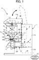
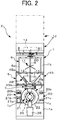
- FIG. 1 and FIG. 2 are overall explanatory diagrams showing an environment for carrying out the invention.
- reference number X denotes a soup supply apparatus.
- Reference number 1 denotes a machine body that includes a pump 2 that supplies, in fixed quantities, soup containing solid ingredients and a pump driving source 3.
- the pump 2 is provided on a front surface of the machine body 1 such as to protrude in a horizontal direction.
- Reference number 4 denotes a control unit that is provided inside the machine body 1.
- the control unit 4 performs various types of control.
- control unit 4 acquires a detection signal from a temperature sensor, and turns ON and OFF a supply power source (high-frequency power) for an induction heating coil; controls a heating temperature for a hopper such that a preset temperature set in a storage unit is maintained; performs control such that a temperature state of the hopper is displayed in a display unit; outputs information related to soup that is stored in the storage unit to an information transmitting means; and turns ON and OFF drive power supplies for the pump driving source 3 and a stirring blade driving source.
- a supply power source high-frequency power
- Reference number 5 denotes a hopper annular support body (hopper cradle) that is integrally provided in the machine body 1 such as to be positioned above the pump.
- Reference number 6 denotes a hopper that freely fits onto a cone-shaped annular wall of the annular support body 5.
- a cone-shaped portion a circular cylindrical portion that is tapered downward
- a short cylindrical lower end portion 6c of the hopper 6 protrudes from a lower surface of the annular support body 5.
- the short cylindrical lower end portion 6c is set in an upper opening of the pump 2 via a connecting means 7 such as to be freely attached and detached.
- Reference number 8 denotes a hopper upper lid (referred to, hereafter, as an "upper lid”).
- a vertical rotation shaft 9 hangs from the upper lid 8 such as freely rotate.
- an axial-direction insertion hole 10 is formed in a small-diameter upper end portion 9a that passes through a substantially center portion of an upper wall 8a of the upper lid 8 that is formed into a substantially cap shape.
- stirring blades 11 that stir soup containing solid ingredients
- a scorch-prevention blade 12 that has a springy resin piece that is in sliding contact with an inner circumferential surface of the cone-shaped portion of the hopper
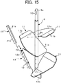
- a pushing blade 13 that pushes food to be consumed towards an upper opening side of the pump 2 are provided (see FIG. 15 ).
- the scorch-prevention blade 12 and the pushing blade 13 are provided in a position below the stirring blades 11.
- the small-diameter upper end portion 9a of the vertical rotation shaft 9 can be inserted into a center hole in the upper lid 8.
- the small-diameter upper end portion 9a protrudes by a predetermined amount from a shaft hole of a bearing member 60 that is fixed to an upper surface of the upper wall 8a of the upper lid 8 by a plurality of fixtures.
- an end surface of the large-diameter long rod-like lower end portion 9b is in contact with a lower surface of the upper wall 8a of the upper lid 8. Therefore, when the components are disassembled, the vertical rotation shaft 9 can be pulled out of the upper lid 8 (see FIG. 9 and FIG. 11 ).
- Reference number 1d denotes an upper-portion housing box that is pivotally mounted on a front surface side of an upper end portion of the machine body 1 by a hinge.
- a stirring motor 14 is provided inside the upper-portion housing box 1d with a motor base plate 14b therebetween.
- An output shaft 14a of the stirring motor 14 and the upper end portion of the vertical rotation shaft 9, described above, are freely engaged and detached by an engaging and detaching means 61 (here, a cylindrical first engaging body 62 that operates together with the output shaft 14a and a cylindrical second engaging body 63 that operates together with the vertical rotation shaft 9), shown in FIG. 7 to FIG. 15 .
- the upper end portion of the vertical rotation shaft 9 is stably supported to the bearing member 60 that is fixed to one side surface of the upper lid 8.
- cylindrical first engaging body 62 on the output shaft 14a side that configures the engaging and detaching means 61 is urged at all times in an engaging direction by an urging means 66. Characteristic matters of the present invention, such as the engaging and detaching means 61 and the urging means 66, will be described hereafter.
- Reference number 1a denotes a lower-portion support base.
- Reference number 1b denotes a vertical control box that is integrally provided above the lower-portion support base 1a and has an opening for discharging heat in a rear wall.
- Reference number 1c denotes a pair of left and right operating boxes that are integrally provided above the lower-portion support base 1a such as to intersect with the vertical control box 1b.
- Reference number 1d denotes the above-described upper-portion housing box. In the upper-portion housing box 1d, a lower edge portion of a rear end portion is connected to an upper-end edge portion of the vertical control box 1b by a hinge.
- the upper-portion housing box 1d can be freely lifted upwards by a hand being inserted into a lower surface of a free end portion of the upper-portion housing box 1d as appropriate.
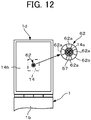
- the cylindrical first engaging body 62 on the output shaft 14a side separates from the cylindrical second engaging body 63 of the vertical rotation shaft 9 (see FIG. 12 ).
- the temperature sensor 55 that detects the temperature of the hopper 6 is provided on a slope-shaped inner circumferential wall 48 between an upper end opening and a lower end opening of the annular support body 5.
- the control unit 4 displays the temperature of the hopper 6 detected by the temperature sensor 55 in a liquid-crystal display unit 21a of an operating panel 20 that is provided in the machine body 1.
- the machine body 1 has the pair of left and right operating boxes 1c and 1c that protrude in a substantially horizontal state from the front wall of the vertical control box (1b) inside which the control unit 4 and a power supply board 17 are provided.
- the operating panel 20 is provided on a front surface of at least either of the pair of left and right operating boxes 1c (such as on the left-side operating box 1c in FIG. 2 ).
- various types of operating buttons 20, such as a power button, a button for selecting the speed of the stirring motor 14, and a button for continuing a discharge state are provided in the operating panel 20.
- an operating button 20c that enables selection between large and small discharge quantities is provided on the front surface of the other operating box 1c (such as on the right-side operating box 1c in FIG. 2 ), as well.
- the box units of the machine body 1 can be arbitrarily changed in design. Therefore, the machine body 1 is not limited to the aspect shown in the drawings.
- the power supply board 17 can be connected to a commercial power supply (alternating current) 19 by a cable 18. Therefore, although an electric circuit is not particularly shown, an alternating current-to-direct current (AC/DC) converter is provided in the power supply board 17.
- AC/DC alternating current-to-direct current
- the control unit 4 controls startup, reversing, and rotation speed of the pump driving source 3 and a stirring driving source 14, and output of high-frequency power to the induction heating coil.
- the plunger-type pump 2 is configured by an outer valve 21, an inner valve 26 that is rotatably provided in the outer valve, and a plunger 30 that moves back and forth within the inner valve.
- a cylindrical pump head 22 is fixedly connected to a tip end portion of the outer valve 21 by a fastening means (such as a screw bolt).
- the cylindrical inner valve 26 that has an opening 27 that is capable of communicating with each of a suction hole (upper opening) 24 and a discharge hole 25 formed in the pump head 22 is provided in the outer valve 21 such as to rotate freely.
- a seal 29 that has a through hole 28 that communicates with the opening 27 of the inner valve 26 and can selectively communicate with the suction hole 24 and the discharge hole 25 is fixedly attached to a wall surface on an axial-direction side of the inner valve 26.
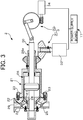
- FIG. 3 schematically shows the pump driving source 3 that supplies, in fixed quantities, soup that is housed in the hopper 6, through the rotation of the inner valve 26 and the back-and-forth movement of the plunger 30 (well-known technology).
- driving force of a first driving source 32 for rotation of the inner valve 26 is transmitted via a power transmitting means 31 to a protruding inner end portion 26a of the inner valve 26 on the right side in FIG. 3 .
- driving force of a second driving source 34 for back-and-forth movement of the plunger 30 is transmitted via a power conversion mechanism 33 to a protruding end portion of the plunger 30.
- the first driving source 32 and the second driving source 34 are electrically connected to the power supply board 17.
- the inner valve 26 is intermittently rotated by a predetermined amount (such as substantially 180 degrees) by the driving force of the first driving source 32.
- the plunger 30 is moved back and forth by the driving force of the second driving source 34, in correspondence with the intermittent rotation of the inner valve 26. Soup (such as soup containing solid ingredients) inside the pump 2 is supplied in a fixed quantity to a cup 35 that is placed below the discharge opening 25.
- the hopper 6 is attached to the suction hole (upper opening) of the pump 2 by a connecting means 7 such as to be freely attached and detached.
- the hopper 6 is composed of a magnetic metal material and formed into a "funnel shape.”
- the hopper 6 according to the present embodiment is configured by a long cylindrical portion 6a of which an upper end portion is a wide opening, a cone-shaped portion 6b, and a short cylindrical portion (lower end portion) 6c that has a small opening and is connected to the cone-shaped portion 6b.
- a flange portion for connection is provided around the short cylindrical portion 6c.
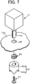
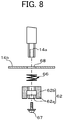
- FIG. 7 is an overall explanatory diagram in which the stirring motor 14 that has the downward-oriented output shaft 14a, the motor base plate 14b that has a through hole in a center portion, a pressing spring 66 that serves as an example of the urging means, the cylindrical first engaging body 62, and a fixture 67 that has a flange-like head portion are in a disassembled state.
- FIG. 8 is an explanatory diagram showing an overall cross-sectional view of the components in FIG. 7 .
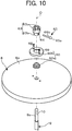
- FIG. 9 is a partial overall cross-sectional explanatory diagram of the cylindrical second engaging body 63, the hopper upper lid 8, and the vertical rotation shaft 9.
- FIG. 10 is an explanatory diagram showing a perspective view of the main sections in FIG. 9 .
- FIG. 11 is an explanatory diagram in which the components shown in FIG. 9 are coupled and shows a state in which the small-diameter upper end portion 9a of the vertical rotation shaft 9 is inserted into the center hole of the hopper upper lid 8 from below.
- the engaging and detaching means 61 is configured by the cylindrical first engaging body 62 that operates together with the output shaft 14a and the second engaging body 63 that operates together with the vertical rotation shaft 9.
- the cylindrical first engaging body 62 on the output shaft 14a side that configures the engaging and detaching means 61 is urged at all times in the engaging direction by the urging means 66;
- the small-diameter upper end portion 9a of the vertical rotation shaft 9 is stably supported to the bearing member 60 that is fixed to one side surface of the upper lid 8.
- a plurality of protrusions in a vertical direction are provided on an outer circumferential surface of the output shaft 14a of the stirring motor 14 shown in an upper portion of the drawings.
- a female screw to which the fixture 67 is screwed in the axial direction is formed on a lower end surface in the output shaft 14a.
- a through hole 68 of the motor base plate 14b is set taking into consideration the radius of the output shaft 14a, the size of the urging means 66, the radius of the cylindrical first engaging body 62, and the like.
- the urging means 66 that is pressed against the lower surface of the motor base plate 14b and the upper surface of the cylindrical first engaging body 62 is a coil spring of a predetermined length.
- the urging means 66 may also be a plate spring that is easily elastically deformed.
- the cylindrical first engaging body 62 is configured by an engaging portion 62a that has downward-oriented protruding portions and recessing portions, and is continuous in the circumferential direction, and a short cylindrical fitting portion 62b that continues from the engaging portion.
- a through hole that corresponds to the output shaft 14a and a plurality of grooves that are in a radially outward direction and communicate with the through hole are formed in the short cylindrical fitting portion 62b.
- a shape of the engaging portion 62a is a matter than can be arbitrarily changed in design.
- the downward-oriented protruding portions and recessing portions can be continuously formed in a wave shape.
- the fixture 67 has the flange-shaped head portion. However, a washer (not shown) may be added.
- the cylindrical second engaging body 63 shown in the upper portion of the drawings is configured by an engaged portion 63a in an upper end portion, and a short cylindrical portion 63b that continues from the engaged portion 63a.
- a through hole through which the small-diameter upper end portion 9a of the vertical rotation shaft 9 passes and an engagement hole 64 that is in the radial direction perpendicular to a center axis line O of the through hole are formed in the short cylindrical portion 63b.
- the engaged portion 63a is composed of upward-oriented recessing portions and protruding portions.
- the cylindrical second engaging body 63 is supported on an upper surface of the bearing member 60 and is capable of rotating in relation to the bearing member 60.
- the bearing member 60 is configured by a short cylindrical bearing 60a that has a flange in a lower end portion and an annular fixing plate 60b that presses the cylindrical bearing against the upper wall of the upper lid 8.
- the annular fixing plate 60b is fixed to the upper wall of the upper lid 8 by a plurality of male screws 69.
- the insertion hole 10 that is formed in the small-diameter upper end portion 9a of the vertical rotation shaft 9 is a vertical elongated hole.
- a lock bolt 65 that can be freely inserted into and removed from the engagement hole 64 and the insertion hole 10 is composed of a spherical or plate-shaped knob portion 65a and a rod-shaped inserting portion 65b that protrudes from the knob portion 65a.
- the main section of the present invention is as follows: "the engaging and detaching means 61 is configured by: the cylindrical first engaging body 62 that is provided in a state such as to be fitted outside the lower end portion of the output shaft 14a of the stirring motor 14 and has the engaging portion 62a; and the cylindrical second engaging body 63 that has the engaged portion 63a that is engaged with and detached from the engaging portion 62a and is provided in a state such as to be fitted outside the upper end portion 9a of the vertical rotation shaft 9 that passes through the substantially center portion of the upper wall 8a.
- the lateral-direction engagement hole 64 that communicates with the insertion hole 10 that is formed in the upper end portion of the vertical rotation shaft 9 is formed in the cylindrical second engaging body 63.
- the rod-shaped inserting portion 65b of the lock bolt 65 is inserted into the engagement hole 64 and the insertion hole 10.
- the upper lid 8 is mounted to the upper end portion of the hopper 6 such as to be freely fitted and detached.
- the vertical rotation shaft 9 hangs downward on the upper surface side of the upper lid 8 with the cylindrical second engaging body 63 therebetween, such as to rotate freely in relation to the upper lid 8.
- reference number 11 denotes a plurality of stirring blades (two stirring blades) that are fixed in an intersecting manner (in an X-shape) in the center portion of the vertical rotation shaft 9. These stirring blades 11 lift the solid ingredients of the soup upwards.
- the stirring blade 11 is configured by a slope-shaped wide portion 11a and a short horizontal portion 11b that is connected to an upper portion of the wide portion 11a. The solid ingredients of the soup come into contact with the short horizontal portion 11b and the wide portion 11a, and are efficiently stirred.
- Reference number 12 denotes a scorch-prevention blade of which a vertical base end portion is fixed to the vertical rotation shaft 9.
- a springy resin piece 41 that is in sliding contact with the inner circumferential surface of the cone-shaped portion 6b of the hopper 6 is detachably mounted.
- the slope-shaped free end portion 12a has a C-shaped cross-section and has a notch 42 in a length direction.
- the springy resin piece 41 is configured by an attachment base end portion 41a that is fitted into the sloped free end portion 12a and a springy sliding-contact portion 41b that protrudes by a predetermined amount in the shape of a long plate from the attachment base end portion 41a with the notch 42 therebetween.
- the springy sliding-contact portion 41b provides a function for scraping off scorch.
- a small protrusion-like stirring portion 12b that extends further downward than a lower end surface of the vertical rotation shaft 9 is provided in a continuous manner.
- the small protrusion-like stirring portion 12b is positioned within a small opening 43 of the short cylindrical portion 6c of the hopper 6 and serves to prevent the solid ingredients of the soup from getting caught inside the short cylindrical portion 6c.
- the vertical rotation shaft 9 has the pushing blade 13 that pushes food to be consumed towards the upper opening side of the pump 2.
- the pushing blade 13 has a shape similar to that of the stirring blade 11.
- the annular support body 5 has the slope-shaped annular wall 48 and is attached in a protruding state to the front surface of the control box 1b such as to be positioned in an exterior space between the left and right operating boxes 1c and 1c, and the upper-portion housing box 1d of the machine body 1.
- the annular support body 5 is configured by a case body 45 that has an upper opening 46 that is formed on an upper wall 45a and a lower opening 47 that is formed on a lower wall 45b, and the cone-shaped annular wall 48 (hopper cradle) that is fixed inside the case body 45 by a flange 48a and a fixing means such as to surround the upper opening 46 and is continuous with the flange 48a.
- a through hole 51 for the temperature sensor is formed in a portion of an upper portion of the above-described cone-shaped annular wall 48.
- a magnetic shield member 52 for protecting the temperature sensor is provided on an inner wall surface of the cone-shaped annular wall 48 such as to be positioned on an outer side of the through hole 51.
- a shape of the magnetic shield member 52 is cylindrical or frame-shaped.
- the magnetic shield member 52 is formed into an upward-facing U-shaped frame such that a support member that supports the temperature sensor 55 does not become deformed as a result of heat generated by an induction heating coil 53 that is wound in a lower portion side of the inner wall surface of the cone-shaped annular wall 48.
- the lower opening 47 of the case body 45 is larger than the upper opening 46.
- the hopper cradle 48 is inserted into the case body 45 from below the case body 45 and the flange 48a thereof is fixed to a lower surface of the upper wall 45a of the case body 45.
- FIG. 16 includes a configuration of a support member 56 that includes the movable temperature sensor 55.
- the support member 56 is fixed to the inner wall surface of the cone-shaped annular wall 48 that serves as the hopper cradle by a plurality of fixing means 57 in a state in which the support member 56 is shielded from the induction heating coil 53.
- the support member 56 is configured by a cylindrical guide support plate 56a that has a stepped cross-section and fits into the through hole 51 of the cone-shaped annular wall 48, and a pipe-shaped support plate 56b that is integrally connected to the cylindrical guide support plate 56a by the plurality of fixing means 57 and has an attachment flange that is provided around a center portion of an outer circumferential wall of a pipe-shaped portion.
- the temperature sensor 55 is such that a tip end portion 55a thereof is urged at all times in a direction coming into contact with an outer surface of the cone-shaped portion 6b of the hopper 6 by a spring member 58 that is provided in the support member 56 via the through hole 51 of the cone-shaped annular wall 48.
- the movable temperature sensor 55 is such that the tip end portion 55a passes through an unnumbered center hole of the cylindrical guide support plate 56 and protrudes by a predetermined amount from the outer wall surface of the cone-shaped annular wall 48, and a large-diameter cylindrical rear end portion 55b that is connected to the tip end portion 55a is fitted around a tip end portion of the pipe-shaped support plate 56b such as to freely slide.
- the spring member 58 is provided inside the temperature sensor 55. One end portion of the spring member 58 pressed against an inner surface of the temperature sensor 55 and the other end portion is pressed against a tip end surface of the second pipe-shaped support plate 56b. Moreover, a connection cable 59 for the temperature sensor 55 is connected to the control unit 4 by passing through the interior of the pipe-shaped support plate 56b.
- the cylindrical guide support plate 56a serves as a guide member that guides the movable temperature sensor 55 in a back-and-forth direction.
- the combination of the temperature sensor 55 and the support member 56 can be arbitrarily changed in design.
- the tip end portion 55a of the temperature sensor 55 protrudes by a predetermined amount as a result of the spring force of the spring member 58. Meanwhile, when the hopper 6 is set in the hopper annular support body 5 as shown in FIG. 16 , the temperature sensor 55 retracts by a predetermined amount into the case body 45 against the spring force of the spring member 58. However, the movable temperature sensor 55 is urged by the spring force of the spring member 58 at all times. Therefore, the tip end portion 55a is reliably in contact with the outer surface of the cone-shaped portion 6b of the hopper 6.
- the power supply board 17 of the control unit 4 is provided in the annular support body 5 that is a part of the machine body 1 or the control box 1b of the machine body 1.
- the power supply board 17 is electrically connected to the induction heating coil 53 by wiring and supplies high-frequency power to the induction heating coil 53.
- the hopper 6 has a three-layer structure that is composed of an inner ferritic stainless steel layer, an outer ferritic stainless steel layer, and an aluminum layer (heating promotion layer) that is interposed between the stainless steel layers.
- ferritic stainless steel is a magnetic metal material. Therefore, when high-frequency power is supplied from the power supply substrate 17 to the induction heating coil 53, the cone-shaped portion 6b of the hopper 6 is induction-heated by so called Joule heating. For example, soup containing solid ingredients is heated to about 120 degrees and boils. As a result, depending on the extent of power supply to the induction heating coil 53 and control of the stirring driving source 14, the inner wall surface of the cone-shaped portion 6b may become scorched.
- the vertical rotation shaft 9 is rotated to the left and right in an alternating manner.
- the stirring blades 11 stir the soup in an even state.
- the scorch-prevention blade 12 also rotates in the rotation direction of the vertical rotation shaft.
- the springy resin piece 41 slides over the inner circumferential surface of the cone-shaped portion 6b of the hopper 6 in a scraping manner.
- the control unit 4 acquires the temperature information detected by the temperature sensor 55. For example, when the food to be consumed is boiled (such as when the preset temperature is 120 degrees), the control unit 4 stops power supply to the induction heating coil 53.
- FIG. 17 is an overall cross-sectional explanatory diagram according to a second embodiment (attachment location of the bearing member 60) of the present invention.
- the matter according to the second embodiment that mainly differs from the first embodiment is that the short cylindrical bearing member 60 is fixedly provided on the lower surface of the center portion of the upper wall of the upper lid 8. In this manner, the bearing member 60 may be provided on either of the upper surface and the lower surface, or both.
- FIG. 18 is a partial overall cross-sectional explanatory diagram according to a third embodiment, from a side view.
- the matter according to the third embodiment that mainly differs from the first embodiment is that the heating means (induction heating coil) 53 is replaces by a cooling means (Peltier element) 53A.
- the cooling means 53A is configured such that, for example, a total of four cooling units 53A that take heat from the soup inside the hopper 6 via the hopper 6 and cool the soup are fixed on the slope-shaped annular circumferential wall 48 that directly or indirectly cradles the cone-shaped portion 6b of the hopper 6 at an predetermined interval in the circumferential direction of the slope-shaped annular circumferential wall 48.
- the cooling units 53A are connected by wiring to the power supply board 17 that supplies power.
- the cooling unit 53A is configured by: an accompanying first cooling plate that has a contact surface that is formed to follow a curvature radius of the outer circumferential surface of the cone-shaped portion 6b of the hopper 6; an electronic cooling element body of which a vertical surface that absorbs heat is provided in surface-contact with a fitting recess portion of an outer wall surface of the accompanying first cooling plate; a second cooling plate of which an inner wall surface is provided in a state of surface-contact with a heat discharge surface of the electronic cooling element body; a plurality of cooling fins that are integrally provided on an outer wall surface of the second cooling plate; and a cooling fan that is provided in accompaniment with the cooling fins.
- the cooling fan, the cooling fins, the second cooling plate, the electronic cooling element body, and the accompanying first cooling pate are integrally engaged by a plurality of unit fixtures and configure a single cooling structural body (Patent Literature 1; publicly known matter).
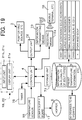
- FIG. 19 shows accompanying matters added to the first embodiment.
- reference numbers 19 and 20 denote operating panels that have the input units 21b and 21c and the display unit 21a.
- Reference number 4 denotes the control unit (calculation processing unit) into which information from the input units is inputted.
- Reference number 71 denotes the storage unit that stores therein a plurality of pieces of information a related to soup, preset temperature information b, pricing information, calorie information, corporate information, and the like.
- Reference number 72 denotes an output unit that outputs results of calculation processes performed by the control unit.
- Reference number 73 denotes an information transmitting means for transmitting the plurality of pieces of information related to soup that are stored in the storage unit to the periphery of the machine body 1 via the output unit 72.
- Reference number 74 denotes a receiving means.
- Reference number 75 denotes a timer.
- Reference number 76 denotes a mobile terminal or the like that is capable of acquiring the plurality of pieces of information in response to the receiving means.
- near-field communication between the machine body 1 that holds the information and the mobile terminal 76 is known communication performed using Bluetooth or the like (such as Japanese Patent Laid-open Publication No. 2003-218763 ).
- the present invention is suitable for cases in which soup is supplied in fixed quantities through a pump while being heated or cooled by a supply source.
Landscapes
- Engineering & Computer Science (AREA)
- Food Science & Technology (AREA)
- Mechanical Engineering (AREA)
- Polymers & Plastics (AREA)
- Life Sciences & Earth Sciences (AREA)
- Chemical & Material Sciences (AREA)
- Nutrition Science (AREA)
- Health & Medical Sciences (AREA)
- Seeds, Soups, And Other Foods (AREA)
- Devices For Dispensing Beverages (AREA)
- Mixers Of The Rotary Stirring Type (AREA)
- Accessories For Mixers (AREA)
- Reciprocating Pumps (AREA)
Abstract
A soup supply apparatus of the present invention is characterized in that, in a soup supply apparatus X that supplies, in fixed quantities, soup that is housed in a hopper through rotation of an inner valve 26 and back-and-forth movement of a plunger 30, an engaging and detaching means 61 is configured by: a cylindrical first engaging body 62 that is provided in a state such as to be fitted outside a lower end portion of an output shaft 14a of a stirring motor and has an engaging portion; and a cylindrical second engaging body 63 that has an engaged portion that is engaged with and detached from the engaging portion and is provided in a state such as to be fitted outside an upper end portion of a vertical rotation shaft. A latera-direction engagement hole 64 that communicates with an insertion hole that is formed in the upper end portion of the vertical rotation shaft is formed in the cylindrical second engaging body. A rod-shaped inserting portion 65b of a lock bolt 65 is inserted into the engagement hole and the insertion hole. When at least a hopper upper lid and the vertical rotation shaft are cleaned, in a state in which a free end portion of an upper-portion housing box of a machine body is lifted upwards and the hopper upper lid is removed from the hopper, the lock bolt is pulled out of the engagement hole and the insertion hole, and the cylindrical second engaging body 63, the vertical rotation shaft 9, and the hopper upper lid 8 can thereby be disassembled. When the hopper upper lid and the vertical rotation shaft that has a stirring blade is cleaned, at least these components (the upper lid and the vertical rotation shaft) can be easily disassembled, and these components can be easily coupled after cleaning as well.
Description
- The present invention relates a soup supply apparatus. In particular, the present invention relates to a soup supply apparatus that supplies, in prescribed quantities, soup containing solid ingredients.
-
Patent Literature 1 toPatent Literature 4 each describe a soup supply apparatus that supplies soup in prescribed quantities. First, a characteristic matter of the supply apparatus inPatent Literature 1 is a "cooling apparatus." The cooling apparatus includes: a machine body that is provided with a pump that supplies soup in fixed quantities and a pump driving source; a hopper that is detachably set in the pump; and an electronic cooling element body that includes a cooling plate that is in direct or indirect surface-contact with a portion in the periphery of the hopper. In addition, the cooling apparatus is configured by: an annular support body that is integrally provided in the machine body; and a control unit that is provided in either of the annular support body and the machine body, and supplies power to the cooling unit via wiring. A plurality of cooling units are provided at a required interval in a circumferential direction in an interior space of the annular support body. - Next, in paragraph 0036, paragraph 0067, and
FIG. 2 ofPatent Literature 2, the following is described with reference to the drawings (reference numbers are those used in Patent Literature 2). That is, a dispensing apparatus X includes afirst driving source 32 and asecond driving source 34. Driving force of thefirst driving source 32 is transmitted to arear end portion 11b of an innercylindrical body 11 via a power transmitting means 33. The innercylindrical body 11 is intermittently rotated by a predetermined amount by the driving force of thefirst driving source 32. Meanwhile, the driving force of asecond driving source 34 is transmitted to a rear end portion of adrive operation rod 30 via apower conversion mechanism 35 that includes a clutch. Thedrive operation rod 32 is moved back and forth to a predetermined position by the driving force of thesecond driving source 34. - Next,
Patent Literature 3 describes the following. That is, the supply apparatus includes: a pump and a pump driving source that are provided on a lower end portion side of a machine body and in which the pump supplies soup in fixed quantities; an upper-portion housing box that is provided in an upper end portion of the machine body such as to freely rotate and in which a stirring driving source is provided therein; a rotation shaft that has a polygonal recessing portion or protruding portion that engages with an output shaft of a vertical shaft of the stirring driving source in an upper end portion that passes through a center portion of a hopper upper lid, and has a stirring blade that stirs the soup in a long rod-like lower end portion; the hopper upper lid that is provided in a portion of the rotation shaft near an upper end portion; a hopper onto which the hopper upper lid is fitted and that has a cone-shaped portion in a lower end portion; an annular support body that supports the cone-shaped portion of the hopper and includes a heating means; and a control unit and a power supply board that are provided in either of the machine body and the annular support body. A temperature sensor that detects a temperature state of the hopper is provided on a wall of the annular support body. - Furthermore,
Patent Literature 4 also describes a soup supply apparatus that supplies, in fixed quantities, soup that is housed in a hopper through rotation of an inner valve and back-and-forth movement of a plunger. The soup is stirred by rotation of a vertical rotation shaft that is connected to a lower end portion of an output shaft of a stirring motor that is fixed to an upper surface of a horizontal support plate that is provided in an upper end portion of a machine body, via an engaging means, and has a stirring blade in a long rod-like lower end portion. - As is clear from the descriptions in
Patent Literature 1 toPatent Literature 4, above, "a soup supply apparatus (X) that includes, in a machine body (1), each of: a pump (2) that includes an outer valve (21) that serves as a fixed member, an inner valve (26) that serves as a rotating member, and a plunger (30) that performs rectilinear motion; a driving source (32, 34) of the pump; an annular support body (5) that is integrally provided in the machine body such as to be positioned above the outer valve; a hopper (6) that is set in an inner wall of the annular support body such as to be freely fitted and detached, and in which a lower end portion is removably coupled with a pump head (22) of the outer valve via a fastening means 23; a hopper upper lid (8) that is fitted onto the hopper such as to be freely fitted and detached; a vertical rotation shaft (9) that passes through a center portion of an upper wall of the hopper upper lid (8) and has a stirring blade in a long rod-like lower end portion; a stirring motor (14) in which an output shaft is connected to the vertical rotation shaft via an engaging and detaching means; an upper-portion housing box (1d) that includes the stirring motor therein and is pivotally supported to an upper end portion of the machine body such as to freely rotate; and a control unit that controls driving of the driving source (32, 34) of the pump, wherein soup that is housed in the hopper is supplied in fixed quantities through rotation of the inner valve (26) and back-and-forth movement of the plunger (30)" is a publicly known technology (reference numbers used inPatent Literature 3 are applied for convenience). - However, in
Patent Literature 1 toPatent Literature 4, the vertical rotation shaft that has the stirring blade, the hopper upper lid that supports the upper end portion of the vertical rotation shaft such as to freely rotate, and a component (an engaging body on the upper lid side) with a polygonal recessing portion or protruding portion on the upper lid side that connects the upper end portion of the vertical rotation shaft and the output shaft of the stirring motor cannot be easily disassembled. Therefore, when cleaning is performed, these components (such as the upper lid and the vertical rotation shaft) are cleaned as is without being disassembled. Consequently, a problem arises in that the hopper upper lid and the vertical rotation shaft cannot be easily and sufficiently cleaned. - In addition, improvements, such as enabling reliable connection between the output shaft of the stirring motor and the upper end portion of the vertical rotation shaft, reliable support such that the vertical rotation shaft does not sway in a radially outward direction, visual confirmation of the temperature state of the temperature of the hopper (the soup housed therein), and acquisition of information regarding the soup by a mobile terminal that is present in the periphery of the machine body, are desired.
- [Patent Literature 1] Japanese Patent Laid-open Publication No.
2005-253355 - [Patent Literature 2]
FIG. 3 of Japanese Patent Laid-open Publication No.2008-195410 - [Patent Literature 3] Re-publication (A1) of International Patent Publication No.
WO2010/050043 - [Patent Literature 4] Re-publication (A1) of International Patent Publication No.
WO2003/031265 - In light of the issues of
Patent Literature 1 toPatent Literature 4, the main object of the present invention is to enable, when a hopper upper lid and a vertical rotation shaft that has a stirring blade are cleaned, at least these components (the hopper upper lid and the vertical rotation shaft) to be easily disassembled, and enable these components to be easily coupled after cleaning as well. In addition, a second object of the present invention is to enable a cylindrical first engaging body on an output shaft side and a cylindrical second engaging body on the vertical rotation shaft side to be easily and reliably engaged by a free end portion of an upper-portion housing box of a machine body being lowered in a downward direction. Furthermore, a third object of the present invention is to support the vertical rotation shaft to the hopper upper lid in a stable state. Other objects are specified by dependent claims. - A soup supply apparatus of the present invention preferably includes, in a
machine body 1, each of: apump 2 that includes anouter valve 21, aninner valve 26, and a plunger that performs rectilinear motion; apump driving source 3; anannular support body 5 that is integrally provided in the machine body such as to be positioned above the outer valve; ahopper 6 that is directly or indirectly set on a wall of the annular support body; a hopperupper lid 8 that is freely fitted onto the hopper; avertical rotation shaft 9 that passes through a center portion of an upper wall of the hopper upper lid and has a stirring blade in a long rod-like lower end portion; a stirringmotor 14 of which a lower end portion of an output shaft and an upper end portion of the vertical rotation shaft are connected by an engaging and detaching means; an upper-portion housing box 1d that includes the stirring motor therein and is pivotally supported to an upper-end edge portion of the machine body such as to freely rotate; and a control unit that controls driving of the pump drive source. In the soup supply apparatus X, soup that is housed in the hopper is supplied in fixed quantities through rotation of theinner valve 26 and back-and-forth movement of theplunger 30. The engaging and detachingmeans 61 is configured by: a cylindrical firstengaging body 62 that is provided in a state such as to be fitted outside a lower end portion of anoutput 14a of the stirring motor and has an engaging portion; and a cylindrical secondengaging body 63 that has an engaged portion that is engaged with and detached from the engaging portion and is provided in a state such as to be fitted outside an upper end portion of the vertical rotation shaft. A lateral-direction engagement hole 64 that communicates with aninsertion hole 10 that is formed in the upper end portion of the vertical rotation shaft is formed in the cylindrical second engaging body. A rod-shapedinserting portion 65b of alock bolt 65 is inserted into the engagement hole and the insertion hole. When at least the hopper upper lid and the vertical rotation shaft are cleaned, in a state in which a free end portion of the upper-portion housing box is lifted upwards and the hopper upper lid is removed from the hopper, the lock bolt is pulled out of the engagement hole and the insertion hole, and the cylindrical secondengaging body 63, thevertical rotation shaft 9, and the hopperupper lid 8 are thereby disassembled. - In the above-described configuration, an urging means 66 that is wound around a stirring motor output shaft that passes through a bottom wall of the upper-portion housing box is provided between the bottom wall of the upper-portion housing box and an upper portion of the cylindrical first engaging body. The urging means urges the cylindrical first engaging body that is provided such as to freely slide in an axial direction of the stirring motor in a direction engaging with the cylindrical second engaging body at all times. In addition, a short cylindrical bearing member that supports the vertical rotation shaft is fixedly provided in a center portion of an upper wall of the hopper
upper lid 8. Furthermore, a temperature sensor that detects a temperature of thehopper 6 is provided on an inner circumferential wall between an upper end opening and a lower end opening of the annular support body. The control unit displays the temperature of the hopper detected by the temperature sensor in a display unit that is provided in themachine body 1. Furthermore, themachine body 1 has a pair of left andright operating boxes 1c that protrude in a substantially horizontal state from a front wall of avertical control box 1b in which the control unit and a power supply board are provided therein. The display unit that displays a temperature of the soup is provided on a front surface of at least either of the pair of left and right operating boxes. Moreover, the control unit transmits at least a plurality of pieces of information related to soup that is stored in the storage unit to the periphery of themachine body 1 via an information transmitting means. -
- (a) According to a first aspect of the invention, in the cylindrical second engaging body that is provided in the upper end portion of the vertical rotation shaft, when cleaning is performed, when the lock bolt that locks the cylindrical second engaging body and the vertical rotation shaft is pulled out in a state in which the free end portion of the upper-portion housing box of the machine body is lifted upwards, both components (the cylindrical second engaging body and the vertical rotation shaft) can be disassembled. In addition, the vertical rotation shaft that has a stirring blade can be pulled out in a downward direction from the hopper upper lid. Therefore, all constituent components are placed in a disassembled state. Consequently, the cylindrical second engaging body, the vertical rotation shaft, and the hopper upper lid can be easily and sufficiently completely cleaned. In addition, the disassembled components can be easily assembled in the reverse order.
- (b) According to a second aspect of the invention, the urging means that is wound around the output shaft that passes through the bottom wall of the upper-portion housing box is provided between the bottom wall of the upper-portion housing box and the upper end portion of the cylindrical first engaging body. The urging means urges the cylindrical first engaging body that is provided such as to freely slide in the axial direction of the output shaft in a direction engaging with the cylindrical second engaging body that is capable of rotating in a predetermined position at all times. Therefore, when the free end portion of the upper-portion housing box of the machine body is lowered downward, the engaging portion of the cylindrical first engaging body and the engaged portion of the cylindrical second engaging body are quickly and reliably engaged.
- (c) According to a third aspect of the invention, the short cylindrical bearing member that supports the vertical rotation shaft is provided in the center portion of the upper wall of the hopper upper lid, such as on either (or both) of an upper surface and a lower surface of the upper wall. Therefore, the vertical rotation shaft can be supported to the hopper upper lid in a stable state.
- (d) According to a fourth aspect and a fifth aspect of the invention, the temperature sensor that detects the temperature of the hopper is provided on the inner circumferential wall between the upper opening and the lower opening of the annular support body. The control unit displays the temperature of the hopper detected by the temperature sensor in the display unit provided in the machine body (1). Therefore, a heating temperature or a cooling temperature of the hopper can be visually confirmed. Consequently, a heating or cooling switch can be freely turned "ON" as desired.
- (e) According to a sixth aspect of the invention, at least a plurality of pieces of information related to soup that is stored in the storage unit can be transmitted to the periphery of the machine body (1) via the information transmitting means. Therefore, a mobile terminal that is capable of acquiring the information can easily ascertain information such as whether the soup is soup that contains solid ingredients, soup that contains no solid ingredients, soup that contains large pieces of solid ingredients, soup that contains small pieces of solid ingredients, soup that contains tofu, vegetable soup, or pork miso soup, the quantity of soup, calories, and price.
-
-
FIG. 1 to FIG. 16 are explanatory diagrams according to a first embodiment of the present invention.FIG. 17 is an overall cross-sectional explanatory diagram according to a second embodiment of the present invention in which a bearing member is fixed to a lower surface of a hopper upper lid.FIG. 18 is an explanatory diagram according to a third embodiment of the present invention in which a cooling means is provided in an annular support body of the present invention. -
FIG. 1 is an overall explanatory diagram from a right-side view. -
FIG. 2 is an overall explanatory diagram from a front view. -
FIG. 3 is an overall cross-sectional explanatory diagram of an example of a pump. -
FIG. 4 is an explanatory diagram of main sections (in a state in which an inner valve is rotated). -
FIG. 5 is an explanatory diagram of the main sections (in a state in which a plunger is retracted). -
FIG. 6A and Fig. 6B are conceptual diagrams of a state of communication of an opening of the inner valve with a suction hole and a discharge hole of an outer valve, in whichFIG. 6A shows a state in which the suction hole of the outer valve and the opening of the inner valve are communicated, whereasFig. 6B shows a state in which the discharge hole of the outer valve and the opening of the inner valve are communicated. -
FIG. 7 is an overall explanatory diagram of main sections. -
FIG. 8 is an explanatory diagram showing an overall cross-sectional view of the main sections inFIG. 7 . -
FIG. 9 is a partial overall cross-sectional explanatory diagram of main sections. -
FIG. 10 is an explanatory diagram showing a perspective view of the main sections inFIG. 9 . -
FIG. 11 is an explanatory diagram in which components shown inFIG. 9 are coupled. -
FIG. 12 is an explanatory diagram of a state in which a free end portion of an upper-portion storage box of a machine body is lifted upwards, from a front view. -
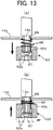
FIG. 13A is an overall explanatory diagram of a state in which an urging means is extended andFIG. 13B is an overall explanatory diagram of a state in which the urging means is contracted. -
FIG. 14 is a perspective view of main sections (a cylindrical second engaging body, a hopper upper lid, a vertical rotation shaft, and an annular support body). -
FIG. 15 is a perspective view of main sections (blades of the vertical rotation shaft). -
FIG. 16 is an explanatory diagram in which a hopper is set in the annular support body (including an enlarged view of a temperature sensor). -
FIG. 17 is an overall cross-sectional explanatory diagram according to a second embodiment of the present invention. -
FIG. 18 is a partial overall cross-sectional explanatory diagram according to a third embodiment of the present invention, from a side view. -
FIG. 19 is a block diagram in which a machine body according to an embodiment includes an information transmitting means. -
- X:
- soup supply apparatus
- 1:
- machine body
- 2:
- pump
- 3:
- pump driving source
- 4:
- control unit
- 5:
- annular support body
- 6:
- hopper
- 6b:
- cone-shaped portion
- 6c:
- lower end portion
- 8:
- hopper upper lid
- 9:
- vertical rotation shaft
- 10:
- insertion hole
- 11:
- stirring blade
- 14:
- stirring motor
- 14a:
- output shaft
- 14b:
- motor base plate
- 20:
- operating panel
- 21a:
- display unit
- 53:
- heating means (mainly an induction heating coil)
- 53A:
- cooling means (mainly a Peltier element)
- 55:
- temperature sensor
- 56:
- support member
- 58:
- spring member
- 61:
- engaging and detaching means
- 62:
- cylindrical first engaging body
- 63:
- cylindrical second engaging body
- 64:
- engagement hole
- 65:
- lock bolt
- 65a:
- knob portion
- 65b:
- rod-shaped inserting portion
- 66:
- urging means
- 67:
- fixture
- 71:
- storage unit
- 73:
- information transmitting means
- A preferred embodiment for carrying out the present invention, shown in
FIG. 1 to FIG. 16 , will hereinafter be described. -
FIG. 1 andFIG. 2 are overall explanatory diagrams showing an environment for carrying out the invention. InFIG. 1 andFIG. 2 , reference number X denotes a soup supply apparatus.Reference number 1 denotes a machine body that includes apump 2 that supplies, in fixed quantities, soup containing solid ingredients and apump driving source 3. Thepump 2 is provided on a front surface of themachine body 1 such as to protrude in a horizontal direction.Reference number 4 denotes a control unit that is provided inside themachine body 1. Thecontrol unit 4 performs various types of control. For example, thecontrol unit 4 acquires a detection signal from a temperature sensor, and turns ON and OFF a supply power source (high-frequency power) for an induction heating coil; controls a heating temperature for a hopper such that a preset temperature set in a storage unit is maintained; performs control such that a temperature state of the hopper is displayed in a display unit; outputs information related to soup that is stored in the storage unit to an information transmitting means; and turns ON and OFF drive power supplies for thepump driving source 3 and a stirring blade driving source. -
Reference number 5 denotes a hopper annular support body (hopper cradle) that is integrally provided in themachine body 1 such as to be positioned above the pump. A support member that includes atemperature sensor 55, described hereafter, is fixed inside theannular support body 5. -
Reference number 6 denotes a hopper that freely fits onto a cone-shaped annular wall of theannular support body 5. When a cone-shaped portion (a circular cylindrical portion that is tapered downward) of thehopper 6 is supported by the above-described cone-shaped annular wall, a short cylindricallower end portion 6c of thehopper 6 protrudes from a lower surface of theannular support body 5. The short cylindricallower end portion 6c is set in an upper opening of thepump 2 via a connectingmeans 7 such as to be freely attached and detached. -
Reference number 8 denotes a hopper upper lid (referred to, hereafter, as an "upper lid"). Avertical rotation shaft 9 hangs from theupper lid 8 such as freely rotate. In thevertical rotation shaft 9, an axial-direction insertion hole 10 is formed in a small-diameterupper end portion 9a that passes through a substantially center portion of anupper wall 8a of theupper lid 8 that is formed into a substantially cap shape. In addition, in a large-diameter long rod-likelower end portion 9b that continues from the small-diameterupper end portion 9a, stirringblades 11 that stir soup containing solid ingredients, a scorch-prevention blade 12 that has a springy resin piece that is in sliding contact with an inner circumferential surface of the cone-shaped portion of the hopper, and a pushingblade 13 that pushes food to be consumed towards an upper opening side of thepump 2 are provided (seeFIG. 15 ). The scorch-prevention blade 12 and the pushingblade 13 are provided in a position below the stirringblades 11. The small-diameterupper end portion 9a of thevertical rotation shaft 9 can be inserted into a center hole in theupper lid 8. In this case, the small-diameterupper end portion 9a protrudes by a predetermined amount from a shaft hole of a bearingmember 60 that is fixed to an upper surface of theupper wall 8a of theupper lid 8 by a plurality of fixtures. In addition, an end surface of the large-diameter long rod-likelower end portion 9b is in contact with a lower surface of theupper wall 8a of theupper lid 8. Therefore, when the components are disassembled, thevertical rotation shaft 9 can be pulled out of the upper lid 8 (seeFIG. 9 andFIG. 11 ). -
Reference number 1d denotes an upper-portion housing box that is pivotally mounted on a front surface side of an upper end portion of themachine body 1 by a hinge. A stirringmotor 14 is provided inside the upper-portion housing box 1d with amotor base plate 14b therebetween. Anoutput shaft 14a of the stirringmotor 14 and the upper end portion of thevertical rotation shaft 9, described above, are freely engaged and detached by an engaging and detaching means 61 (here, a cylindrical firstengaging body 62 that operates together with theoutput shaft 14a and a cylindrical secondengaging body 63 that operates together with the vertical rotation shaft 9), shown inFIG. 7 to FIG. 15 . In addition, the upper end portion of thevertical rotation shaft 9 is stably supported to the bearingmember 60 that is fixed to one side surface of theupper lid 8. Furthermore, the cylindrical firstengaging body 62 on theoutput shaft 14a side that configures the engaging and detaching means 61 is urged at all times in an engaging direction by an urging means 66. Characteristic matters of the present invention, such as the engaging and detaching means 61 and the urging means 66, will be described hereafter. - The
machine body 1 will be further described.Reference number 1a denotes a lower-portion support base.Reference number 1b denotes a vertical control box that is integrally provided above the lower-portion support base 1a and has an opening for discharging heat in a rear wall.Reference number 1c denotes a pair of left and right operating boxes that are integrally provided above the lower-portion support base 1a such as to intersect with thevertical control box 1b.Reference number 1d denotes the above-described upper-portion housing box. In the upper-portion housing box 1d, a lower edge portion of a rear end portion is connected to an upper-end edge portion of thevertical control box 1b by a hinge. Therefore, for example, the upper-portion housing box 1d can be freely lifted upwards by a hand being inserted into a lower surface of a free end portion of the upper-portion housing box 1d as appropriate. In this case, the cylindrical firstengaging body 62 on theoutput shaft 14a side separates from the cylindrical secondengaging body 63 of the vertical rotation shaft 9 (seeFIG. 12 ). - Here, regarding dependent matters of the present invention, the
temperature sensor 55 that detects the temperature of thehopper 6 is provided on a slope-shaped innercircumferential wall 48 between an upper end opening and a lower end opening of theannular support body 5. Thecontrol unit 4 displays the temperature of thehopper 6 detected by thetemperature sensor 55 in a liquid-crystal display unit 21a of anoperating panel 20 that is provided in themachine body 1. According to the embodiment, as shown inFIG. 1 , themachine body 1 has the pair of left andright operating boxes control unit 4 and apower supply board 17 are provided. Therefore, the operatingpanel 20 is provided on a front surface of at least either of the pair of left andright operating boxes 1c (such as on the left-side operating box 1c inFIG. 2 ). In addition to thedisplay unit 21a, various types ofoperating buttons 20, such as a power button, a button for selecting the speed of the stirringmotor 14, and a button for continuing a discharge state, are provided in theoperating panel 20. In addition, anoperating button 20c that enables selection between large and small discharge quantities is provided on the front surface of theother operating box 1c (such as on the right-side operating box 1c inFIG. 2 ), as well. The box units of themachine body 1 can be arbitrarily changed in design. Therefore, themachine body 1 is not limited to the aspect shown in the drawings. - In addition, the
power supply board 17 can be connected to a commercial power supply (alternating current) 19 by acable 18. Therefore, although an electric circuit is not particularly shown, an alternating current-to-direct current (AC/DC) converter is provided in thepower supply board 17. In addition, when the operating buttons (switches) 20b and 20c on the operatingboxes 1c are pressed, signals thereof are sent to astorage unit 71. For example, thecontrol unit 4 then controls startup, reversing, and rotation speed of thepump driving source 3 and astirring driving source 14, and output of high-frequency power to the induction heating coil. - As is commonly known, the plunger-
type pump 2 is configured by anouter valve 21, aninner valve 26 that is rotatably provided in the outer valve, and aplunger 30 that moves back and forth within the inner valve. Here, as shown inFIG. 3 , acylindrical pump head 22 is fixedly connected to a tip end portion of theouter valve 21 by a fastening means (such as a screw bolt). The cylindricalinner valve 26 that has anopening 27 that is capable of communicating with each of a suction hole (upper opening) 24 and adischarge hole 25 formed in thepump head 22 is provided in theouter valve 21 such as to rotate freely. - In addition, a
seal 29 that has a throughhole 28 that communicates with theopening 27 of theinner valve 26 and can selectively communicate with thesuction hole 24 and thedischarge hole 25 is fixedly attached to a wall surface on an axial-direction side of theinner valve 26. -
FIG. 3 schematically shows thepump driving source 3 that supplies, in fixed quantities, soup that is housed in thehopper 6, through the rotation of theinner valve 26 and the back-and-forth movement of the plunger 30 (well-known technology). When simply described, driving force of afirst driving source 32 for rotation of theinner valve 26 is transmitted via a power transmitting means 31 to a protrudinginner end portion 26a of theinner valve 26 on the right side inFIG. 3 . In addition, driving force of asecond driving source 34 for back-and-forth movement of theplunger 30 is transmitted via apower conversion mechanism 33 to a protruding end portion of theplunger 30. Furthermore, thefirst driving source 32 and thesecond driving source 34 are electrically connected to thepower supply board 17. - In the
pump 2, to enable soup containing solid ingredients to be supplied in fixed quantities from thehopper 6, theinner valve 26 is intermittently rotated by a predetermined amount (such as substantially 180 degrees) by the driving force of thefirst driving source 32. Theplunger 30 is moved back and forth by the driving force of thesecond driving source 34, in correspondence with the intermittent rotation of theinner valve 26. Soup (such as soup containing solid ingredients) inside thepump 2 is supplied in a fixed quantity to acup 35 that is placed below thedischarge opening 25. - The
hopper 6 is attached to the suction hole (upper opening) of thepump 2 by a connectingmeans 7 such as to be freely attached and detached. Thehopper 6 is composed of a magnetic metal material and formed into a "funnel shape." Thehopper 6 according to the present embodiment is configured by a longcylindrical portion 6a of which an upper end portion is a wide opening, a cone-shapedportion 6b, and a short cylindrical portion (lower end portion) 6c that has a small opening and is connected to the cone-shapedportion 6b. A flange portion for connection is provided around the shortcylindrical portion 6c. Here, a configuration of the connectingmeans 7 that directly or indirectly engages the short cylindrical portion (lower end portion) 6c of thehopper 6 and thepump head 22 will be omitted. -
FIG. 7 is an overall explanatory diagram in which the stirringmotor 14 that has the downward-orientedoutput shaft 14a, themotor base plate 14b that has a through hole in a center portion, apressing spring 66 that serves as an example of the urging means, the cylindrical firstengaging body 62, and afixture 67 that has a flange-like head portion are in a disassembled state. In addition,FIG. 8 is an explanatory diagram showing an overall cross-sectional view of the components inFIG. 7 . - Furthermore,
FIG. 9 is a partial overall cross-sectional explanatory diagram of the cylindrical secondengaging body 63, the hopperupper lid 8, and thevertical rotation shaft 9.FIG. 10 is an explanatory diagram showing a perspective view of the main sections inFIG. 9 .FIG. 11 is an explanatory diagram in which the components shown inFIG. 9 are coupled and shows a state in which the small-diameterupper end portion 9a of thevertical rotation shaft 9 is inserted into the center hole of the hopperupper lid 8 from below. - The engaging and detaching means 61 according to the present embodiment is configured by the cylindrical first
engaging body 62 that operates together with theoutput shaft 14a and the secondengaging body 63 that operates together with thevertical rotation shaft 9. When the characteristic matters of the present invention are simply described: (a)a lower end portion of theoutput shaft 14a of the stirringmotor 14 and an upper end portion of the above-describedvertical rotation shaft 9 are freely engaged and detached by the engaging and detaching means 61; (b) in addition, the cylindrical firstengaging body 62 on theoutput shaft 14a side that configures the engaging and detaching means 61 is urged at all times in the engaging direction by the urging means 66; (c) and further, the small-diameterupper end portion 9a of thevertical rotation shaft 9 is stably supported to the bearingmember 60 that is fixed to one side surface of theupper lid 8. Hereafter, descriptions of matters that can be easily inferred by a person skilled in the art are simply described. Reference numbers are also omitted. - First, in
FIG. 7 andFIG. 8 , a plurality of protrusions in a vertical direction are provided on an outer circumferential surface of theoutput shaft 14a of the stirringmotor 14 shown in an upper portion of the drawings. In addition, a female screw to which thefixture 67 is screwed in the axial direction is formed on a lower end surface in theoutput shaft 14a. A throughhole 68 of themotor base plate 14b is set taking into consideration the radius of theoutput shaft 14a, the size of the urging means 66, the radius of the cylindrical firstengaging body 62, and the like. The urging means 66 that is pressed against the lower surface of themotor base plate 14b and the upper surface of the cylindrical firstengaging body 62 is a coil spring of a predetermined length. However, the urging means 66 may also be a plate spring that is easily elastically deformed. - The cylindrical first
engaging body 62 is configured by an engagingportion 62a that has downward-oriented protruding portions and recessing portions, and is continuous in the circumferential direction, and a short cylindricalfitting portion 62b that continues from the engaging portion. A through hole that corresponds to theoutput shaft 14a and a plurality of grooves that are in a radially outward direction and communicate with the through hole are formed in the short cylindricalfitting portion 62b. A shape of the engagingportion 62a is a matter than can be arbitrarily changed in design. For example, the downward-oriented protruding portions and recessing portions can be continuously formed in a wave shape. Thefixture 67 has the flange-shaped head portion. However, a washer (not shown) may be added. - Next, in
FIG. 9 ,FIG. 10 , andFIG. 11 , the cylindrical secondengaging body 63 shown in the upper portion of the drawings is configured by an engagedportion 63a in an upper end portion, and a shortcylindrical portion 63b that continues from the engagedportion 63a. A through hole through which the small-diameterupper end portion 9a of thevertical rotation shaft 9 passes and anengagement hole 64 that is in the radial direction perpendicular to a center axis line O of the through hole are formed in the shortcylindrical portion 63b. The engagedportion 63a is composed of upward-oriented recessing portions and protruding portions. - As shown in
FIG. 11 , the cylindrical secondengaging body 63 is supported on an upper surface of the bearingmember 60 and is capable of rotating in relation to the bearingmember 60. The bearingmember 60 is configured by a shortcylindrical bearing 60a that has a flange in a lower end portion and anannular fixing plate 60b that presses the cylindrical bearing against the upper wall of theupper lid 8. Theannular fixing plate 60b is fixed to the upper wall of theupper lid 8 by a plurality ofmale screws 69. In addition, theinsertion hole 10 that is formed in the small-diameterupper end portion 9a of thevertical rotation shaft 9 is a vertical elongated hole. Furthermore, alock bolt 65 that can be freely inserted into and removed from theengagement hole 64 and theinsertion hole 10 is composed of a spherical or plate-shapedknob portion 65a and a rod-shaped insertingportion 65b that protrudes from theknob portion 65a. - Therefore, with reference to the main object of the present invention and
FIG. 9 to FIG. 11 , the main section of the present invention is as follows: "the engaging and detaching means 61 is configured by: the cylindrical firstengaging body 62 that is provided in a state such as to be fitted outside the lower end portion of theoutput shaft 14a of the stirringmotor 14 and has the engagingportion 62a; and the cylindrical secondengaging body 63 that has the engagedportion 63a that is engaged with and detached from the engagingportion 62a and is provided in a state such as to be fitted outside theupper end portion 9a of thevertical rotation shaft 9 that passes through the substantially center portion of theupper wall 8a. The lateral-direction engagement hole 64 that communicates with theinsertion hole 10 that is formed in the upper end portion of thevertical rotation shaft 9 is formed in the cylindrical secondengaging body 63. The rod-shaped insertingportion 65b of thelock bolt 65 is inserted into theengagement hole 64 and theinsertion hole 10. When at least theupper lid 8 and thevertical rotation shaft 9 are cleaned, in a state in which the free end portion of the upper-portion housing box 1d of themachine body 1 is lifted upwards and the hopper upper lid is removed from the hopper, thelock bolt 65 is pulled out of theengagement hole 64 and theinsertion hole 10. As a result, the cylindrical secondengaging body 63, thevertical rotation shaft 9, and theupper lid 8 can be disassembled." - The
upper lid 8 is mounted to the upper end portion of thehopper 6 such as to be freely fitted and detached. In addition, thevertical rotation shaft 9 hangs downward on the upper surface side of theupper lid 8 with the cylindrical secondengaging body 63 therebetween, such as to rotate freely in relation to theupper lid 8. In addition,reference number 11 denotes a plurality of stirring blades (two stirring blades) that are fixed in an intersecting manner (in an X-shape) in the center portion of thevertical rotation shaft 9. These stirringblades 11 lift the solid ingredients of the soup upwards. According to the present embodiment, the stirringblade 11 is configured by a slope-shapedwide portion 11a and a shorthorizontal portion 11b that is connected to an upper portion of thewide portion 11a. The solid ingredients of the soup come into contact with the shorthorizontal portion 11b and thewide portion 11a, and are efficiently stirred. -
Reference number 12 denotes a scorch-prevention blade of which a vertical base end portion is fixed to thevertical rotation shaft 9. In a slope-shapedfree end portion 12a of the scorch-prevention blade 12, aspringy resin piece 41 that is in sliding contact with the inner circumferential surface of the cone-shapedportion 6b of thehopper 6 is detachably mounted. - As shown in
FIG. 15 , the slope-shapedfree end portion 12a has a C-shaped cross-section and has anotch 42 in a length direction. Thespringy resin piece 41 is configured by an attachmentbase end portion 41a that is fitted into the slopedfree end portion 12a and a springy sliding-contact portion 41b that protrudes by a predetermined amount in the shape of a long plate from the attachmentbase end portion 41a with thenotch 42 therebetween. The springy sliding-contact portion 41b provides a function for scraping off scorch. - Here, according to the present embodiment, in a lower end of the attachment base end portion of the scorch-
prevention blade 12, a small protrusion-like stirring portion 12b that extends further downward than a lower end surface of thevertical rotation shaft 9 is provided in a continuous manner. The small protrusion-like stirring portion 12b is positioned within asmall opening 43 of the shortcylindrical portion 6c of thehopper 6 and serves to prevent the solid ingredients of the soup from getting caught inside the shortcylindrical portion 6c. In addition, on the side opposite the scorch-prevention blade 12, thevertical rotation shaft 9 has the pushingblade 13 that pushes food to be consumed towards the upper opening side of thepump 2. The pushingblade 13 has a shape similar to that of thestirring blade 11. - The
annular support body 5 has the slope-shapedannular wall 48 and is attached in a protruding state to the front surface of thecontrol box 1b such as to be positioned in an exterior space between the left andright operating boxes portion housing box 1d of themachine body 1. - As shown in
FIG. 16 , theannular support body 5 is configured by acase body 45 that has anupper opening 46 that is formed on anupper wall 45a and alower opening 47 that is formed on alower wall 45b, and the cone-shaped annular wall 48 (hopper cradle) that is fixed inside thecase body 45 by aflange 48a and a fixing means such as to surround theupper opening 46 and is continuous with theflange 48a. - In addition, a through
hole 51 for the temperature sensor is formed in a portion of an upper portion of the above-described cone-shapedannular wall 48. Furthermore, amagnetic shield member 52 for protecting the temperature sensor is provided on an inner wall surface of the cone-shapedannular wall 48 such as to be positioned on an outer side of the throughhole 51. - A shape of the
magnetic shield member 52 is cylindrical or frame-shaped. According to the present embodiment, themagnetic shield member 52 is formed into an upward-facing U-shaped frame such that a support member that supports thetemperature sensor 55 does not become deformed as a result of heat generated by aninduction heating coil 53 that is wound in a lower portion side of the inner wall surface of the cone-shapedannular wall 48. Here, thelower opening 47 of thecase body 45 is larger than theupper opening 46. Thehopper cradle 48 is inserted into thecase body 45 from below thecase body 45 and theflange 48a thereof is fixed to a lower surface of theupper wall 45a of thecase body 45. -
FIG. 16 includes a configuration of asupport member 56 that includes themovable temperature sensor 55. Thesupport member 56 is fixed to the inner wall surface of the cone-shapedannular wall 48 that serves as the hopper cradle by a plurality of fixing means 57 in a state in which thesupport member 56 is shielded from theinduction heating coil 53. - In addition, the
support member 56 is configured by a cylindricalguide support plate 56a that has a stepped cross-section and fits into the throughhole 51 of the cone-shapedannular wall 48, and a pipe-shapedsupport plate 56b that is integrally connected to the cylindricalguide support plate 56a by the plurality of fixing means 57 and has an attachment flange that is provided around a center portion of an outer circumferential wall of a pipe-shaped portion. - The
temperature sensor 55 is such that atip end portion 55a thereof is urged at all times in a direction coming into contact with an outer surface of the cone-shapedportion 6b of thehopper 6 by aspring member 58 that is provided in thesupport member 56 via the throughhole 51 of the cone-shapedannular wall 48. - In addition, the
movable temperature sensor 55 is such that thetip end portion 55a passes through an unnumbered center hole of the cylindricalguide support plate 56 and protrudes by a predetermined amount from the outer wall surface of the cone-shapedannular wall 48, and a large-diameter cylindricalrear end portion 55b that is connected to thetip end portion 55a is fitted around a tip end portion of the pipe-shapedsupport plate 56b such as to freely slide. - Furthermore, the
spring member 58 is provided inside thetemperature sensor 55. One end portion of thespring member 58 pressed against an inner surface of thetemperature sensor 55 and the other end portion is pressed against a tip end surface of the second pipe-shapedsupport plate 56b. Moreover, a connection cable 59 for thetemperature sensor 55 is connected to thecontrol unit 4 by passing through the interior of the pipe-shapedsupport plate 56b. - Here, the cylindrical
guide support plate 56a serves as a guide member that guides themovable temperature sensor 55 in a back-and-forth direction. In addition, the combination of thetemperature sensor 55 and thesupport member 56 can be arbitrarily changed in design. - Before the
hopper 6 is set in the hopperannular support body 5, thetip end portion 55a of thetemperature sensor 55 protrudes by a predetermined amount as a result of the spring force of thespring member 58. Meanwhile, when thehopper 6 is set in the hopperannular support body 5 as shown inFIG. 16 , thetemperature sensor 55 retracts by a predetermined amount into thecase body 45 against the spring force of thespring member 58. However, themovable temperature sensor 55 is urged by the spring force of thespring member 58 at all times. Therefore, thetip end portion 55a is reliably in contact with the outer surface of the cone-shapedportion 6b of thehopper 6. - The
power supply board 17 of thecontrol unit 4 is provided in theannular support body 5 that is a part of themachine body 1 or thecontrol box 1b of themachine body 1. Thepower supply board 17 is electrically connected to theinduction heating coil 53 by wiring and supplies high-frequency power to theinduction heating coil 53. - Although not particularly shown, the
hopper 6 has a three-layer structure that is composed of an inner ferritic stainless steel layer, an outer ferritic stainless steel layer, and an aluminum layer (heating promotion layer) that is interposed between the stainless steel layers. - As is well known, ferritic stainless steel is a magnetic metal material. Therefore, when high-frequency power is supplied from the
power supply substrate 17 to theinduction heating coil 53, the cone-shapedportion 6b of thehopper 6 is induction-heated by so called Joule heating. For example, soup containing solid ingredients is heated to about 120 degrees and boils. As a result, depending on the extent of power supply to theinduction heating coil 53 and control of the stirring drivingsource 14, the inner wall surface of the cone-shapedportion 6b may become scorched. - Therefore, according to the present embodiment, when food to be consumed that is housed within the hopper is heated and boiled, the
vertical rotation shaft 9 is rotated to the left and right in an alternating manner. When thevertical rotation shaft 9 is rotated, the stirringblades 11 stir the soup in an even state. In addition, the scorch-prevention blade 12 also rotates in the rotation direction of the vertical rotation shaft. At this time, thespringy resin piece 41 slides over the inner circumferential surface of the cone-shapedportion 6b of thehopper 6 in a scraping manner. In addition, thecontrol unit 4 acquires the temperature information detected by thetemperature sensor 55. For example, when the food to be consumed is boiled (such as when the preset temperature is 120 degrees), thecontrol unit 4 stops power supply to theinduction heating coil 53. - Hereafter, in this section, other embodiments of the present invention will be described with reference to
FIG. 17 to FIG. 19 . Here, regarding the descriptions of the embodiments, sections identical to those according to the first embodiment are given the same or similar reference numbers. Redundant descriptions are omitted. - First,
FIG. 17 is an overall cross-sectional explanatory diagram according to a second embodiment (attachment location of the bearing member 60) of the present invention. The matter according to the second embodiment that mainly differs from the first embodiment is that the short cylindrical bearingmember 60 is fixedly provided on the lower surface of the center portion of the upper wall of theupper lid 8. In this manner, the bearingmember 60 may be provided on either of the upper surface and the lower surface, or both. - Next,
FIG. 18 is a partial overall cross-sectional explanatory diagram according to a third embodiment, from a side view. The matter according to the third embodiment that mainly differs from the first embodiment is that the heating means (induction heating coil) 53 is replaces by a cooling means (Peltier element) 53A. The cooling means 53A is configured such that, for example, a total of fourcooling units 53A that take heat from the soup inside thehopper 6 via thehopper 6 and cool the soup are fixed on the slope-shaped annularcircumferential wall 48 that directly or indirectly cradles the cone-shapedportion 6b of thehopper 6 at an predetermined interval in the circumferential direction of the slope-shaped annularcircumferential wall 48. The coolingunits 53A are connected by wiring to thepower supply board 17 that supplies power. - Here, to improve the cooling effect, the
cooling unit 53A is configured by: an accompanying first cooling plate that has a contact surface that is formed to follow a curvature radius of the outer circumferential surface of the cone-shapedportion 6b of thehopper 6; an electronic cooling element body of which a vertical surface that absorbs heat is provided in surface-contact with a fitting recess portion of an outer wall surface of the accompanying first cooling plate; a second cooling plate of which an inner wall surface is provided in a state of surface-contact with a heat discharge surface of the electronic cooling element body; a plurality of cooling fins that are integrally provided on an outer wall surface of the second cooling plate; and a cooling fan that is provided in accompaniment with the cooling fins. The cooling fan, the cooling fins, the second cooling plate, the electronic cooling element body, and the accompanying first cooling pate are integrally engaged by a plurality of unit fixtures and configure a single cooling structural body (Patent Literature 1; publicly known matter). - Lastly,
FIG. 19 shows accompanying matters added to the first embodiment. InFIG. 19 ,reference numbers input units display unit 21a.Reference number 4 denotes the control unit (calculation processing unit) into which information from the input units is inputted.Reference number 71 denotes the storage unit that stores therein a plurality of pieces of information a related to soup, preset temperature information b, pricing information, calorie information, corporate information, and the like.Reference number 72 denotes an output unit that outputs results of calculation processes performed by the control unit. Reference number 73 denotes an information transmitting means for transmitting the plurality of pieces of information related to soup that are stored in the storage unit to the periphery of themachine body 1 via theoutput unit 72.Reference number 74 denotes a receiving means.Reference number 75 denotes a timer. Reference number 76 denotes a mobile terminal or the like that is capable of acquiring the plurality of pieces of information in response to the receiving means. Here, near-field communication between themachine body 1 that holds the information and the mobile terminal 76 is known communication performed using Bluetooth or the like (such as Japanese Patent Laid-open Publication No.2003-218763 - The present invention is suitable for cases in which soup is supplied in fixed quantities through a pump while being heated or cooled by a supply source.
Claims (6)
- A soup supply apparatus comprising:in a machine body (1),a pump (2) that includes an outer valve (21), an inner valve (26), and a plunger (30) that performs rectilinear motion,a pump driving source (3),an annular support body (5) that is integrally provided in the machine body such as to be positioned above the outer valve,a hopper (6) that is directly or indirectly set on a wall of the annular support body,a hopper upper lid (8) that is freely fitted onto the hopper,a vertical rotation shaft (9) that passes through a center portion of an upper wall of the hopper upper lid and has a stirring blade in a long rod-like lower end portion,a stirring motor (14) of which a lower end portion of an output shaft and an upper end portion of the vertical rotation shaft are connected by an engaging and detaching means,an upper-portion housing box (1d) that includes the stirring motor therein and is pivotally supported to an upper-end edge portion of the machine body such as to freely rotate, anda control unit that controls driving of the pump drive source, whereinsoup that is housed in the hopper is supplied in fixed quantities through rotation of the inner valve (26) and back-and-forth movement of the plunger (30),the engaging and detaching means (61) is configured by a cylindrical first engaging body (62) that is provided in a state such as to be fitted outside a lower end portion of an output shaft (14a) of the stirring motor and has an engaging portion, and a cylindrical second engaging body (63) that has an engaged portion that is engaged with and detached from the engaging portion and is provided in a state such as to be fitted outside an upper end portion of the vertical rotation shaft,a lateral-direction engagement hole (64) that communicates with an insertion hole (10) that is formed in the upper end portion of the vertical rotation shaft is formed in the cylindrical second engaging body,a rod-shaped inserting portion (65b) of a lock bolt (65) is inserted into the engagement hole and the insertion hole, andwhen at least the hopper upper lid and the vertical rotation shaft are cleaned, in a state in which a free end portion of the upper-portion housing box is lifted upwards and the hopper upper lid is removed from the hopper, the lock bolt is pulled out of the engagement hole and the insertion hole, and the cylindrical second engaging body (63), the vertical rotation shaft (9), and the hopper upper lid (8) are thereby disassembled.
- The soup supply apparatus according to claim 1, characterized in that:an urging means (66) that is wound around a stirring motor output shaft that passes through a bottom wall of the upper-portion housing box (1d) is provided between the bottom wall of the upper-portion housing box and an upper portion of the cylindrical first engaging body; andthe urging means urges the cylindrical first engaging body that is provided such as to freely slide in an axial direction of the stirring motor in a direction engaging with the cylindrical second engaging body that is capable of rotating in a predetermined position at all times.
- The soup supply apparatus according to claim 1, characterized in that:
a short cylindrical bearing member (60) that supports the vertical rotation shaft is fixedly provided in a center portion of an upper wall of the hopper upper lid (8). - The soup supply apparatus according to claim 1, characterized in that:a temperature sensor (55) that detects a temperature of the hopper (6) is provided on an inner circumferential wall between an upper end opening and a lower end opening of the annular support body, andthe control unit displays the temperature of the hopper detected by the temperature sensor in a display unit (21a) that is provided in the machine body (1).
- The soup supply apparatus according to claim 4, characterized in that:the machine body (1) has a pair of left and right operating boxes (1c) that protrude in a substantially horizontal state from a front wall of a vertical control box (1b) in which the control unit and a power supply board are provided therein, andthe display unit (21a) that displays a temperature of the soup is provided on a front surface of at least either of the pair of left and right operating boxes.
- The soup supply apparatus according to claim 1, characterized in that:
the control unit transmits at least a plurality of pieces of information related to soup that is stored in the storage unit to the periphery of the machine body (1) via an information transmitting means.
Applications Claiming Priority (1)
| Application Number | Priority Date | Filing Date | Title |
|---|---|---|---|
| PCT/JP2016/004937 WO2018092177A1 (en) | 2016-11-21 | 2016-11-21 | Soup supply apparatus |
Publications (1)
| Publication Number | Publication Date |
|---|---|
| EP3542645A1 true EP3542645A1 (en) | 2019-09-25 |
Family
ID=62145383
Family Applications (1)
| Application Number | Title | Priority Date | Filing Date |
|---|---|---|---|
| EP16921641.3A Withdrawn EP3542645A1 (en) | 2016-11-21 | 2016-11-21 | Soup supply apparatus |
Country Status (6)
| Country | Link |
|---|---|
| US (1) | US20190343339A1 (en) |
| EP (1) | EP3542645A1 (en) |
| JP (1) | JP6749598B2 (en) |
| KR (1) | KR20190087432A (en) |
| CN (1) | CN110167359A (en) |
| WO (1) | WO2018092177A1 (en) |
Families Citing this family (8)
| Publication number | Priority date | Publication date | Assignee | Title |
|---|---|---|---|---|
| WO2021127029A1 (en) | 2019-12-16 | 2021-06-24 | June Life, Inc. | Cooking appliance accessory and method of use |
| CN113099565B (en) | 2021-04-12 | 2023-05-05 | 赫高餐饮设备(苏州)有限公司 | Electromagnetic heating system and apparatus |
| USD1007224S1 (en) | 2021-06-11 | 2023-12-12 | June Life, Inc. | Cooking vessel |
| USD978600S1 (en) | 2021-06-11 | 2023-02-21 | June Life, Inc. | Cooking vessel |
| CN113401522B (en) * | 2021-06-16 | 2022-05-27 | 华能左权煤电有限责任公司 | Automatic cleaning equipment of feed bin |
| CN113828238B (en) * | 2021-11-26 | 2022-02-11 | 潍坊市宇虹防水材料(集团)有限公司 | Preparation method of heat-insulating waterproof coating |
| JP7690244B2 (en) * | 2023-02-09 | 2025-06-10 | 株式会社一蘭 | Temperature measuring device and supply device for seasoning liquid |
| CN117141920B (en) * | 2023-10-11 | 2025-12-02 | 抚顺独凤轩骨神生物技术股份有限公司 | A soup pot with real-time soup base display effect |
Family Cites Families (16)
| Publication number | Priority date | Publication date | Assignee | Title |
|---|---|---|---|---|
| JP3033113U (en) * | 1996-07-02 | 1997-01-21 | 株式会社フジマック | Soup dispenser |
| JPH1118944A (en) * | 1997-07-02 | 1999-01-26 | Orion Mach Co Ltd | Cooking equipment |
| US6513421B2 (en) * | 2000-10-04 | 2003-02-04 | Kazumasa Ikuta | Subdividing apparatus for ingredients-contained soup |
| JP2003031265A (en) | 2001-07-12 | 2003-01-31 | Japan Storage Battery Co Ltd | Non-aqueous electrolyte secondary battery |
| EP1426292A4 (en) | 2001-08-06 | 2006-04-12 | Bay City Service Ltd | High-speed fluid sorting and charging device |
| JP2003218763A (en) | 2002-01-17 | 2003-07-31 | Matsushita Electric Ind Co Ltd | Devices capable of wireless communication |
| JP4388393B2 (en) | 2004-03-11 | 2009-12-24 | 株式会社ベイシティサービス | Cooling device for food and drink |
| JP2008195410A (en) | 2007-02-09 | 2008-08-28 | Bay City Service Co Ltd | Dispensing device for soups |
| DE502007005070D1 (en) * | 2007-11-01 | 2010-10-28 | Mettler Toledo Ag | Stirrer unit comprising an adapter |
| JP2010050043A (en) | 2008-08-25 | 2010-03-04 | Sharp Corp | Fuel cell |
| JP5376535B2 (en) * | 2008-10-31 | 2013-12-25 | 尚之 生田 | Induction heating equipment for soups |
| CN102202547B (en) * | 2008-11-10 | 2014-05-07 | 生田尚之 | Stirrer of soup |
| JP5637587B2 (en) * | 2010-06-14 | 2014-12-10 | 佐竹化学機械工業株式会社 | Detachable coupling of mixing shaft of stirring device |
| WO2014054301A1 (en) * | 2012-10-05 | 2014-04-10 | 株式会社 東芝 | Cooking device |
| CN205024211U (en) * | 2015-10-12 | 2016-02-10 | 嘉兴卓盛生物科技有限公司 | Improvement structure biological enzyme mixer |
| CN205514228U (en) * | 2016-02-26 | 2016-08-31 | 中山市美斯特实业有限公司 | Removable blade of broken wall machine |
-
2016
- 2016-11-21 US US16/461,437 patent/US20190343339A1/en not_active Abandoned
- 2016-11-21 EP EP16921641.3A patent/EP3542645A1/en not_active Withdrawn
- 2016-11-21 JP JP2018550887A patent/JP6749598B2/en not_active Expired - Fee Related
- 2016-11-21 CN CN201680091994.XA patent/CN110167359A/en active Pending
- 2016-11-21 KR KR1020197014478A patent/KR20190087432A/en not_active Withdrawn
- 2016-11-21 WO PCT/JP2016/004937 patent/WO2018092177A1/en not_active Ceased
Also Published As
| Publication number | Publication date |
|---|---|
| JPWO2018092177A1 (en) | 2019-10-10 |
| JP6749598B2 (en) | 2020-09-02 |
| WO2018092177A1 (en) | 2018-05-24 |
| CN110167359A (en) | 2019-08-23 |
| US20190343339A1 (en) | 2019-11-14 |
| KR20190087432A (en) | 2019-07-24 |
Similar Documents
| Publication | Publication Date | Title |
|---|---|---|
| EP3542645A1 (en) | Soup supply apparatus | |
| US8348186B2 (en) | Food mixers and processors | |
| US7291812B2 (en) | Programmable cooker | |
| EP4218505B1 (en) | Sous vide cooker | |
| JP2008545942A (en) | Food temperature setting using wireless technology | |
| TW201436750A (en) | Power supply mixing vessel | |
| CN202981697U (en) | A detachable unit for stirring liquid food or drink | |
| EP3082380B1 (en) | Cooking apparatus | |
| KR20180028642A (en) | Cooking apparatus and controlling method of cooking apparatus | |
| US20180199584A1 (en) | Device, system and method for producing a yoghurt product | |
| CN103565301A (en) | Electric food processing machine | |
| JP5588323B2 (en) | Analysis equipment | |
| JP5376535B2 (en) | Induction heating equipment for soups | |
| EP3777621B1 (en) | Blender | |
| US7511633B2 (en) | Extension cord capable of providing estimated power costs incurred by an electrical appliance plugged thereinto | |
| CN105592762B (en) | Kitchen machine with splash guard | |
| CN105919463A (en) | Food processing machine | |
| US20230324049A1 (en) | Portable Induction Cooking Device | |
| CN202723654U (en) | Liquid food foaming machine with novel agitating device | |
| US12144462B2 (en) | Heating cooking apparatus and built-in heating cooking system | |
| JP2016007247A (en) | Mixing adapter | |
| KR20140128652A (en) | A cooking appartus | |
| CN109744901B (en) | Food processor and display control device and method thereof | |
| JP7224187B2 (en) | Contactless power receiving device and contactless power supply system |
Legal Events
| Date | Code | Title | Description |
|---|---|---|---|
| PUAI | Public reference made under article 153(3) epc to a published international application that has entered the european phase |
Free format text: ORIGINAL CODE: 0009012 |
|
| 17P | Request for examination filed |
Effective date: 20190521 |
|
| AK | Designated contracting states |
Kind code of ref document: A1 Designated state(s): AL AT BE BG CH CY CZ DE DK EE ES FI FR GB GR HR HU IE IS IT LI LT LU LV MC MK MT NL NO PL PT RO RS SE SI SK SM TR |
|
| AX | Request for extension of the european patent |
Extension state: BA ME |
|
| DAV | Request for validation of the european patent (deleted) | ||
| DAX | Request for extension of the european patent (deleted) | ||
| STAA | Information on the status of an ep patent application or granted ep patent |
Free format text: STATUS: THE APPLICATION IS DEEMED TO BE WITHDRAWN |
|
| 18D | Application deemed to be withdrawn |
Effective date: 20200603 |