EP3541661B1 - Additional brake light for rear vehicle window having light guides - Google Patents
Additional brake light for rear vehicle window having light guides Download PDFInfo
- Publication number
- EP3541661B1 EP3541661B1 EP17798314.5A EP17798314A EP3541661B1 EP 3541661 B1 EP3541661 B1 EP 3541661B1 EP 17798314 A EP17798314 A EP 17798314A EP 3541661 B1 EP3541661 B1 EP 3541661B1
- Authority
- EP
- European Patent Office
- Prior art keywords
- light
- leg
- light guide
- optical element
- additional brake
- Prior art date
- Legal status (The legal status is an assumption and is not a legal conclusion. Google has not performed a legal analysis and makes no representation as to the accuracy of the status listed.)
- Active
Links
Images


Classifications
-
- F—MECHANICAL ENGINEERING; LIGHTING; HEATING; WEAPONS; BLASTING
- F21—LIGHTING
- F21S—NON-PORTABLE LIGHTING DEVICES; SYSTEMS THEREOF; VEHICLE LIGHTING DEVICES SPECIALLY ADAPTED FOR VEHICLE EXTERIORS
- F21S43/00—Signalling devices specially adapted for vehicle exteriors, e.g. brake lamps, direction indicator lights or reversing lights
- F21S43/40—Signalling devices specially adapted for vehicle exteriors, e.g. brake lamps, direction indicator lights or reversing lights characterised by the combination of reflectors and refractors
-
- B—PERFORMING OPERATIONS; TRANSPORTING
- B60—VEHICLES IN GENERAL
- B60Q—ARRANGEMENT OF SIGNALLING OR LIGHTING DEVICES, THE MOUNTING OR SUPPORTING THEREOF OR CIRCUITS THEREFOR, FOR VEHICLES IN GENERAL
- B60Q1/00—Arrangement of optical signalling or lighting devices, the mounting or supporting thereof or circuits therefor
- B60Q1/26—Arrangement of optical signalling or lighting devices, the mounting or supporting thereof or circuits therefor the devices being primarily intended to indicate the vehicle, or parts thereof, or to give signals, to other traffic
- B60Q1/30—Arrangement of optical signalling or lighting devices, the mounting or supporting thereof or circuits therefor the devices being primarily intended to indicate the vehicle, or parts thereof, or to give signals, to other traffic for indicating rear of vehicle, e.g. by means of reflecting surfaces
- B60Q1/302—Arrangement of optical signalling or lighting devices, the mounting or supporting thereof or circuits therefor the devices being primarily intended to indicate the vehicle, or parts thereof, or to give signals, to other traffic for indicating rear of vehicle, e.g. by means of reflecting surfaces mounted in the vicinity, e.g. in the middle, of a rear window
-
- B—PERFORMING OPERATIONS; TRANSPORTING
- B60—VEHICLES IN GENERAL
- B60Q—ARRANGEMENT OF SIGNALLING OR LIGHTING DEVICES, THE MOUNTING OR SUPPORTING THEREOF OR CIRCUITS THEREFOR, FOR VEHICLES IN GENERAL
- B60Q1/00—Arrangement of optical signalling or lighting devices, the mounting or supporting thereof or circuits therefor
- B60Q1/26—Arrangement of optical signalling or lighting devices, the mounting or supporting thereof or circuits therefor the devices being primarily intended to indicate the vehicle, or parts thereof, or to give signals, to other traffic
- B60Q1/44—Arrangement of optical signalling or lighting devices, the mounting or supporting thereof or circuits therefor the devices being primarily intended to indicate the vehicle, or parts thereof, or to give signals, to other traffic for indicating braking action or preparation for braking, e.g. by detection of the foot approaching the brake pedal
-
- F—MECHANICAL ENGINEERING; LIGHTING; HEATING; WEAPONS; BLASTING
- F21—LIGHTING
- F21S—NON-PORTABLE LIGHTING DEVICES; SYSTEMS THEREOF; VEHICLE LIGHTING DEVICES SPECIALLY ADAPTED FOR VEHICLE EXTERIORS
- F21S43/00—Signalling devices specially adapted for vehicle exteriors, e.g. brake lamps, direction indicator lights or reversing lights
- F21S43/20—Signalling devices specially adapted for vehicle exteriors, e.g. brake lamps, direction indicator lights or reversing lights characterised by refractors, transparent cover plates, light guides or filters
- F21S43/235—Light guides
- F21S43/236—Light guides characterised by the shape of the light guide
- F21S43/237—Light guides characterised by the shape of the light guide rod-shaped
-
- F—MECHANICAL ENGINEERING; LIGHTING; HEATING; WEAPONS; BLASTING
- F21—LIGHTING
- F21S—NON-PORTABLE LIGHTING DEVICES; SYSTEMS THEREOF; VEHICLE LIGHTING DEVICES SPECIALLY ADAPTED FOR VEHICLE EXTERIORS
- F21S43/00—Signalling devices specially adapted for vehicle exteriors, e.g. brake lamps, direction indicator lights or reversing lights
- F21S43/20—Signalling devices specially adapted for vehicle exteriors, e.g. brake lamps, direction indicator lights or reversing lights characterised by refractors, transparent cover plates, light guides or filters
- F21S43/235—Light guides
- F21S43/242—Light guides characterised by the emission area
- F21S43/243—Light guides characterised by the emission area emitting light from one or more of its extremities
-
- F—MECHANICAL ENGINEERING; LIGHTING; HEATING; WEAPONS; BLASTING
- F21—LIGHTING
- F21S—NON-PORTABLE LIGHTING DEVICES; SYSTEMS THEREOF; VEHICLE LIGHTING DEVICES SPECIALLY ADAPTED FOR VEHICLE EXTERIORS
- F21S43/00—Signalling devices specially adapted for vehicle exteriors, e.g. brake lamps, direction indicator lights or reversing lights
- F21S43/20—Signalling devices specially adapted for vehicle exteriors, e.g. brake lamps, direction indicator lights or reversing lights characterised by refractors, transparent cover plates, light guides or filters
- F21S43/235—Light guides
- F21S43/242—Light guides characterised by the emission area
- F21S43/245—Light guides characterised by the emission area emitting light from one or more of its major surfaces
-
- F—MECHANICAL ENGINEERING; LIGHTING; HEATING; WEAPONS; BLASTING
- F21—LIGHTING
- F21S—NON-PORTABLE LIGHTING DEVICES; SYSTEMS THEREOF; VEHICLE LIGHTING DEVICES SPECIALLY ADAPTED FOR VEHICLE EXTERIORS
- F21S43/00—Signalling devices specially adapted for vehicle exteriors, e.g. brake lamps, direction indicator lights or reversing lights
- F21S43/20—Signalling devices specially adapted for vehicle exteriors, e.g. brake lamps, direction indicator lights or reversing lights characterised by refractors, transparent cover plates, light guides or filters
- F21S43/235—Light guides
- F21S43/249—Light guides with two or more light sources being coupled into the light guide
-
- F—MECHANICAL ENGINEERING; LIGHTING; HEATING; WEAPONS; BLASTING
- F21—LIGHTING
- F21S—NON-PORTABLE LIGHTING DEVICES; SYSTEMS THEREOF; VEHICLE LIGHTING DEVICES SPECIALLY ADAPTED FOR VEHICLE EXTERIORS
- F21S43/00—Signalling devices specially adapted for vehicle exteriors, e.g. brake lamps, direction indicator lights or reversing lights
- F21S43/30—Signalling devices specially adapted for vehicle exteriors, e.g. brake lamps, direction indicator lights or reversing lights characterised by reflectors
- F21S43/31—Optical layout thereof
- F21S43/315—Optical layout thereof using total internal reflection
-
- F—MECHANICAL ENGINEERING; LIGHTING; HEATING; WEAPONS; BLASTING
- F21—LIGHTING
- F21S—NON-PORTABLE LIGHTING DEVICES; SYSTEMS THEREOF; VEHICLE LIGHTING DEVICES SPECIALLY ADAPTED FOR VEHICLE EXTERIORS
- F21S43/00—Signalling devices specially adapted for vehicle exteriors, e.g. brake lamps, direction indicator lights or reversing lights
- F21S43/30—Signalling devices specially adapted for vehicle exteriors, e.g. brake lamps, direction indicator lights or reversing lights characterised by reflectors
- F21S43/33—Signalling devices specially adapted for vehicle exteriors, e.g. brake lamps, direction indicator lights or reversing lights characterised by reflectors characterised by their material, surface treatment or coatings
-
- F—MECHANICAL ENGINEERING; LIGHTING; HEATING; WEAPONS; BLASTING
- F21—LIGHTING
- F21S—NON-PORTABLE LIGHTING DEVICES; SYSTEMS THEREOF; VEHICLE LIGHTING DEVICES SPECIALLY ADAPTED FOR VEHICLE EXTERIORS
- F21S43/00—Signalling devices specially adapted for vehicle exteriors, e.g. brake lamps, direction indicator lights or reversing lights
- F21S43/10—Signalling devices specially adapted for vehicle exteriors, e.g. brake lamps, direction indicator lights or reversing lights characterised by the light source
- F21S43/13—Signalling devices specially adapted for vehicle exteriors, e.g. brake lamps, direction indicator lights or reversing lights characterised by the light source characterised by the type of light source
- F21S43/14—Light emitting diodes [LED]
-
- G—PHYSICS
- G03—PHOTOGRAPHY; CINEMATOGRAPHY; ANALOGOUS TECHNIQUES USING WAVES OTHER THAN OPTICAL WAVES; ELECTROGRAPHY; HOLOGRAPHY
- G03H—HOLOGRAPHIC PROCESSES OR APPARATUS
- G03H1/00—Holographic processes or apparatus using light, infrared or ultraviolet waves for obtaining holograms or for obtaining an image from them; Details peculiar thereto
- G03H1/22—Processes or apparatus for obtaining an optical image from holograms
- G03H1/2202—Reconstruction geometries or arrangements
Definitions
- the present invention concerns an additional brake light of a motor vehicle according to the preamble of claim 1.
- Additional brake light also known as the third brake light, is used on motor vehicles in order to warn other participants in road traffic which have partially blocked view to the left and right brake light of the vehicle.
- the third brake light is formed in a manner to comprise at least one light source and at least one holographic element, whereby the holographic element is configured to refract and/or mirror light beams travelling from the light source.
- the brake light described therein comprises a light source, a hologram and transparent prism for supporting the hologram and for guiding the light of the light source to the hologram.
- the prism with the hologram is mounted in front of the rear window of a vehicle with the light source beneath the surface of the rear panel that is adjacent the rear window.
- EP 2 354 637 A2 describes a rear light for a motor vehicle in which a series of light-emitting diodes (LEDs) is provided as the light source.
- the light from the light-emitting diodes enters a light guide through an entry surface, which splits into two differently shaped parts at a distance from the entry surface.
- the light of the light-emitting diodes emerges from the two parts during operation of the rear light. In this case, the same lighting function is assigned to each of the two parts.
- EP 0 452 815 A1 describes a brake light for a motor vehicle in which a hologram is arranged on the rear window of the vehicle.
- the light emitted by a light source is coupled into the rear window via a light guide and a prism. In the rear window, the light moves to the hologram and enters the hologram from the rear window.
- Additional brake light also known as the third brake light according to the invention aggregates several optical functions in a single optical system.
- the first optical function represents an additional brake light, for example, whereas the second optical function can be represented as an emergency light warning about the danger, lighting of the surrounding, display of various information and similar, and an arbitrary combination thereof.
- at least one optical function can be active, if needed, however, it is possible to simultaneously activate several optical functions.
- Each optical function separately creates a required light distribution by means of the same optical system such as a thick-wall optical guide, at least one hologram being arranged thereon. Furthermore, it is provided for that each optical function utilises at least one section of said thick-wall optical guide or an arbitrary combination of sections of said light guide.
- Fig. 6 does not show a brake light according to the invention and is present in the description for illustration purposes only.
- Fig. 1 shows a motor vehicle 1 comprising an additional brake light 3 arranged in the area of the back thereof, preferably in the area of the rear glass 2.
- Said additional brake light 3 is formed as a thick-wall light guide 4 with at least one optical element 5, 6 arranged thereon, and comprises at least one light source 7, 8 to which a primary optical element can optionally be attached, such as a lens to improve directing of the light beams.
- said light guide 4 is formed as a flat light guide.
- the light guide 4 viewed in transversal direction of the vehicle 1, at least partially extends over the rear glass 2 and comprises an entry surface 4.1 and an exit surface 4.2. Said entry surface 4.1 at least approximately faces the roof of the vehicle 1, whereas said exit surface 4.2 at least approximately faces the direction opposite the vehicle 1 driving direction.
- the light guide 4 is formed in the cross-section as a dual leg element in the sense of the letter L.
- the first leg that is the vertical leg 4.3 of the light guide 4 is located approximately in the plane of said rear glass 2 of the vehicle 1 and is attached inside the vehicle 1 with its the first end to the roof of the vehicle, for example.
- the second leg that is the horizontal leg 4.4 which is associated with the second end of the first leg 4.3 is located approximately horizontally and, respectively, approximately in parallel with the plane of the road surface the vehicle 1 drives over.
- said first leg 4.3 is formed at the first end thereof with the entry surface 4.1 extending approximately perpendicularly to the extension of the first leg 4.3
- said second leg 4.4 is formed at the fee end thereof, that is the end averted from the connection with the first leg 4.3, with the exit surface 4.2.
- said first leg 4.3 can be inclined with regard to the vertical for an angle in the range of about ⁇ 30°, and/or that said second leg 4.4 can be inclined with regard to the horizontal for an angle in the range of about ⁇ 30°.
- Said first leg 4.3 and said second leg 4.4 of the light guide 4 are typically interconnected so that the internal angle ⁇ thereof preferably lies in the range of the obtuse angle.
- At least one optical element 5 is provided on at least one flat side of at least one of the legs 4.3, 4.4 of the light guide 4, preferably at the first, vertical leg 4.3 of the light guide 4, when viewed in transversal direction of the vehicle 1 and, respectively, in longitudinal direction of the light guide 4.
- Said at least one optical element 5 is provided at the flat side of the vertical leg 4.3 of the light guide 4 which is averted from the rear glass 2 of the vehicle 1.
- at least one additional optical element 6 is provided on said exit surface 4.2 of the light guide 4.
- said optical elements 5, 6 are formed as a holographic film which is attached by means of an adhesive agent for example to the respective surface of the light guide 4.
- the optical elements 5, 6 can be formed either as usual prismatic and/or lens optical element and/or as an etched structure and/or by use of different material (a diffusion material for example) by means of two-component injection technology and similar and the combination of the aforementioned. Moreover, at least one of the optical elements 5, 6 can be formed in a manner that it extends continuously over the entire length of the light guide 4. It is provided for according to one of the possible and particularly preferred embodiments that at least one of the optical elements 5, 6 is formed in a manner that it extends intermittently at least over a part of the length of the light guide 4. In the latter case, said optical element 5 is provided as a plurality of mutually more or less equally spaced sections 5.1 of the optical element. In addition, at least one of the optical elements 5, 6 can be formed in a manner to emit multi colour light.
- FIG. 6 A second embodiment of a thick-wall light guide 4, which is not part of the invention, is shown in Fig. 6 .
- the second leg 4.4 is absent and said exit surface 4.2 is provided at the free end of the vertical leg 4.3 of the light guide 4.
- the exit surface 4.2 can be formed as a inclined surface extending under an angle with regard to the extension of the vertical leg 4.3, whereby said inclined surface mostly faces the rear glass 2 of the vehicle 1.
- a first light source 7 provided preferably to perform a primary optical function of the brake light 3 that is to warn a driver behind about breaking.
- Said light source 7 is preferably, but not limited to, selected as at least one light emitting diode (LED), preferably a plurality LED, arranged more or less equally along the light guide 4.
- said light source 7 is arranged with regard to the light guide 4 in a sense for the light beam(s) from the light source 7 and, respectively, from each LED directly hit(s) said entry surface 4.1.
- the light beam(s) from said light source 7 and, respectively, from each LED enter(s) through the entry surface 4.1 into the light guide 4 and, afterwards, travel(s) along the legs 4.3, 4.4 pursuant to the total internal reflection, and exit(s) through the exit surface 4.2. It is possible, of course, that said light source 7 in addition to performing said primary optical function of the brake light 2 can also perform arbitrary additional optical functions that can be controlled in a manner known per se by means of a control unit not shown.
- said optical element 5, which is provided on at least one flat side of at least one leg 4.3, 4.4 of the light guide 4 and preferably on the first that is the vertical leg 4.3 of the light guide 4, can be illuminated by means of a second light source 8.
- Said light source 8 is preferably, but not limited to, selected as at least one LED, preferably a plurality LED, arranged more or less equally along the light guide 4.
- each said light source 8 is arranged with regard to the light guide 4 and, respectively, with regard to each optical element 5 in a sense for the light beam(s) from the light source 8 and, respectively, from each LED directly hit(s) said optical element 5 and, respectively, each said section 5.1 of the optical element 5.
- each LED of the light source 8 to be surrounded with light reflecting inclined walls 9 in a sense of a screen on all sides except the side facing the said optical element 5 and, respectively, facing each said section 5.1 of the optical element 5.
- Said walls 9 are formed in a manner that they divergently extend away from each other in direction from LED toward the optical element 5 and, respectively, the section 5.1 of said optical element, so that light beam(s) from each LED of the light source 8 fall solely to the area of the section 5.1 of said optical element, whereby beam(s) from each neighbouring LED of the light source 8 do not interfere with each other.
- the optical element 5 and, respectively, the plurality of sections 5.1 of the optical element is intended to perform various optical functions.
- a function of an emergency brake light is provided in a case of danger which operates so that the required light distribution is generated by the optical element 5 and, respectively, each section 5.1 of the optical element on the surface of the leg 4.3 of the light guide 4 where the optical element 5 and, respectively, the section 5.1 of the optical element is designed to be.
- the light beam(s) reflect(s) from the optical element 5 and, respectively, from each section 5.1 of the optical element, and exit(s) pursuant to the total internal reflection in direction approximately perpendicular to the leg 4.3 of the light guide 4 and, respectively, in direction towards the rear glass 2 of the vehicle 1.
- said light source 8 in addition to performing said optical function of warning about the danger can also perform arbitrary additional optical functions that can be controlled in a manner known per se by means of a control unit not shown.
- the thick-wall light guide 4 is completely transparent in the area of the vertical leg 4.3 with the completely transparent optical element 5.
- the thick-wall light guide 4 is also completely transparent in the area of the exit surface 4.2.
- the thick-wall light guide 4 is transparent in the area of the vertical leg 4.3 with the completely transparent optical element 5.
- the exit surface 4.2 is lit and generates required light distribution such as an additional brake light for instance.
- Only one function is active such as an emergency brake light for instance.
- the area of the vertical leg 4.3 with entirely transparent optical element 5 is lit and generates required optical distribution such as an emergency brake light.
- the exit surface 4.2 is not lit.
- the light source 8 for lighting of the optical element 5 and, respectively, the plurality of sections 5.1 of the optical element can be arranged in front of the optical element 5 and, respectively, the plurality of sections 5.1, or behind it.
- the additional brake light 3 can be arranged anywhere in and, respectively, on the vehicle 1 such as inside the vehicle 1 just below the roof, in the area above the boot shelf and similar.
- the hologram can be provided as a monochromatic or polychromatic volume hologram, or as a monochromatic or polychromatic surface hologram, or the combination thereof.
- the light beam(s) from LED at least partially overlap, thus, obtaining an additional optical effect on the optical element 5 and, respectively, on the plurality of sections 5.1 of the optical element.
Landscapes
- Engineering & Computer Science (AREA)
- General Engineering & Computer Science (AREA)
- Mechanical Engineering (AREA)
- Lighting Device Outwards From Vehicle And Optical Signal (AREA)
Description
- The present invention concerns an additional brake light of a motor vehicle according to the preamble of
claim 1. - Additional brake light, also known as the third brake light, is used on motor vehicles in order to warn other participants in road traffic which have partially blocked view to the left and right brake light of the vehicle.
- An additional brake light of the aforementioned type is known from
US 5 347 435 A . In this document is disclosed how to represent an additional brake light by means of a hologram so that no or just small amount of additional equipment is to be installed in the rear window section, whereby the driver's field of vision is substantially increased. However, the disclosed solution requires a relatively complex and intricate optics. - Moreover, it is disclosed in the document
DE 10 2011 012 520 A1 that the third brake light is formed in a manner to comprise at least one light source and at least one holographic element, whereby the holographic element is configured to refract and/or mirror light beams travelling from the light source. - Another additional brake light of a motor vehicle is known from
US 5 101 193 A . The brake light described therein comprises a light source, a hologram and transparent prism for supporting the hologram and for guiding the light of the light source to the hologram. The prism with the hologram is mounted in front of the rear window of a vehicle with the light source beneath the surface of the rear panel that is adjacent the rear window. -
EP 2 354 637 A2 describes a rear light for a motor vehicle in which a series of light-emitting diodes (LEDs) is provided as the light source. The light from the light-emitting diodes enters a light guide through an entry surface, which splits into two differently shaped parts at a distance from the entry surface. The light of the light-emitting diodes emerges from the two parts during operation of the rear light. In this case, the same lighting function is assigned to each of the two parts. -
EP 0 452 815 A1 describes a brake light for a motor vehicle in which a hologram is arranged on the rear window of the vehicle. The light emitted by a light source is coupled into the rear window via a light guide and a prism. In the rear window, the light moves to the hologram and enters the hologram from the rear window. - Therefore, known solutions are limited only to the additional brake light and, respectively, to the use of a hologram as the additional brake light, and does not allow any additional function.
- It is the object of the present invention to create an additional brake light of the type mentioned above which in addition to its basic optical function i.e. creating a warning light signal in order to inform the driver in the rear about the braking also provides at least one additional lighting function.
- This is achieved, in accordance with the invention, by means of a headlamp of the aforementioned kind with the characterizing features of
claim 1. The subclaims concern preferred forms of the invention. -
Claim 1 provides that - the light guide is formed in a cross-section as a dual leg element in the sense of the letter L, wherein a first leg thereof when mounted in the vehicle is a vertical leg and located approximately in the plane of said rear glass of the vehicle, and wherein a second leg thereof when mounted in the vehicle is a horizontal leg which is associated with a second end of the first leg and located approximately horizontally, respectively, approximately in parallel with the plane of the road surface the vehicle drives over, and wherein said first leg is formed at the first end thereof with an entry surface, and said second leg is formed at the free end thereof with an exit surface, that
- a first light source is arranged in the immediate vicinity of said entry surface of the light guide, so that the light beam from the light source enters through the entry surface into the light guide and afterwards, travels along the legs pursuant to the total internal reflection, and exits through the exit surface performing a primary optical function of the brake light, and that
- □said optical element provided on at least one flat side of at least one of the legs of the light guide can be lit by means of a second light source to perform a second optical function of the brake light.
- Additional brake light, also known as the third brake light according to the invention aggregates several optical functions in a single optical system. The first optical function represents an additional brake light, for example, whereas the second optical function can be represented as an emergency light warning about the danger, lighting of the surrounding, display of various information and similar, and an arbitrary combination thereof. It is possible according to the present invention for at least one optical function to be active, if needed, however, it is possible to simultaneously activate several optical functions. Each optical function separately creates a required light distribution by means of the same optical system such as a thick-wall optical guide, at least one hologram being arranged thereon. Furthermore, it is provided for that each optical function utilises at least one section of said thick-wall optical guide or an arbitrary combination of sections of said light guide.
- The invention is further described in detail by way of non-limiting embodiment, and with a reference to the accompanying drawings, where
-
Fig. 1 shows a back view of a motor vehicle; -
Fig. 2 shows an enlarged view of an additional brake light according to the invention in a sectional view along the longitudinal vertical plane of the vehicle ofFig. 1 ; -
Fig. 3 shows a sectional view of the additional brake light along the line III-III ofFig. 2 ; -
Fig. 4 shows a sectional view of the additional brake light along the line IV-IV ofFig. 2 ; -
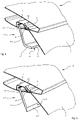
Fig. 5 shows a three-dimensional view of the additional brake light ofFig. 2 ; -
Fig. 6 shows a three-dimensional view of a second embodiment of an additional brake light which is not covered by the invention. - The embodiment illustrated in
Fig. 6 does not show a brake light according to the invention and is present in the description for illustration purposes only. -
Fig. 1 shows amotor vehicle 1 comprising anadditional brake light 3 arranged in the area of the back thereof, preferably in the area of therear glass 2. Saidadditional brake light 3 is formed as a thick-wall light guide 4 with at least oneoptical element light source light guide 4 is formed as a flat light guide. - It is provided for according to one of the possible embodiments of the thick-wall light guide 4 (
Fig. 2 ) that thelight guide 4, viewed in transversal direction of thevehicle 1, at least partially extends over therear glass 2 and comprises an entry surface 4.1 and an exit surface 4.2. Said entry surface 4.1 at least approximately faces the roof of thevehicle 1, whereas said exit surface 4.2 at least approximately faces the direction opposite thevehicle 1 driving direction. Thelight guide 4 is formed in the cross-section as a dual leg element in the sense of the letter L. The first leg that is the vertical leg 4.3 of thelight guide 4 is located approximately in the plane of saidrear glass 2 of thevehicle 1 and is attached inside thevehicle 1 with its the first end to the roof of the vehicle, for example. The second leg that is the horizontal leg 4.4 which is associated with the second end of the first leg 4.3 is located approximately horizontally and, respectively, approximately in parallel with the plane of the road surface thevehicle 1 drives over. In the present embodiment, said first leg 4.3 is formed at the first end thereof with the entry surface 4.1 extending approximately perpendicularly to the extension of the first leg 4.3, whereas said second leg 4.4 is formed at the fee end thereof, that is the end averted from the connection with the first leg 4.3, with the exit surface 4.2. It is provided for according to the present invention that said first leg 4.3 can be inclined with regard to the vertical for an angle in the range of about ±30°, and/or that said second leg 4.4 can be inclined with regard to the horizontal for an angle in the range of about ±30°. Said first leg 4.3 and said second leg 4.4 of thelight guide 4 are typically interconnected so that the internal angle α thereof preferably lies in the range of the obtuse angle. - At least one
optical element 5 is provided on at least one flat side of at least one of the legs 4.3, 4.4 of thelight guide 4, preferably at the first, vertical leg 4.3 of thelight guide 4, when viewed in transversal direction of thevehicle 1 and, respectively, in longitudinal direction of thelight guide 4. Said at least oneoptical element 5 is provided at the flat side of the vertical leg 4.3 of thelight guide 4 which is averted from therear glass 2 of thevehicle 1. Optionally, at least one additionaloptical element 6 is provided on said exit surface 4.2 of thelight guide 4. According to the present invention, saidoptical elements light guide 4. Furthermore, theoptical elements optical elements light guide 4. It is provided for according to one of the possible and particularly preferred embodiments that at least one of theoptical elements light guide 4. In the latter case, saidoptical element 5 is provided as a plurality of mutually more or less equally spaced sections 5.1 of the optical element. In addition, at least one of theoptical elements - A second embodiment of a thick-
wall light guide 4, which is not part of the invention, is shown inFig. 6 . With this example, the second leg 4.4 is absent and said exit surface 4.2 is provided at the free end of the vertical leg 4.3 of thelight guide 4. With said second embodiment, the exit surface 4.2 can be formed as a inclined surface extending under an angle with regard to the extension of the vertical leg 4.3, whereby said inclined surface mostly faces therear glass 2 of thevehicle 1. - In the immediate vicinity of said entry surface 4.1 of the
light guide 4 is arranged afirst light source 7 provided preferably to perform a primary optical function of thebrake light 3 that is to warn a driver behind about breaking. Saidlight source 7 is preferably, but not limited to, selected as at least one light emitting diode (LED), preferably a plurality LED, arranged more or less equally along thelight guide 4. Here, saidlight source 7 is arranged with regard to thelight guide 4 in a sense for the light beam(s) from thelight source 7 and, respectively, from each LED directly hit(s) said entry surface 4.1. The light beam(s) from saidlight source 7 and, respectively, from each LED enter(s) through the entry surface 4.1 into thelight guide 4 and, afterwards, travel(s) along the legs 4.3, 4.4 pursuant to the total internal reflection, and exit(s) through the exit surface 4.2. It is possible, of course, that saidlight source 7 in addition to performing said primary optical function of thebrake light 2 can also perform arbitrary additional optical functions that can be controlled in a manner known per se by means of a control unit not shown. - Further is provided according to the invention that said
optical element 5, which is provided on at least one flat side of at least one leg 4.3, 4.4 of thelight guide 4 and preferably on the first that is the vertical leg 4.3 of thelight guide 4, can be illuminated by means of asecond light source 8. Saidlight source 8 is preferably, but not limited to, selected as at least one LED, preferably a plurality LED, arranged more or less equally along thelight guide 4. Here, each saidlight source 8 is arranged with regard to thelight guide 4 and, respectively, with regard to eachoptical element 5 in a sense for the light beam(s) from thelight source 8 and, respectively, from each LED directly hit(s) saidoptical element 5 and, respectively, each said section 5.1 of theoptical element 5. According to the present invention said feature is achieved by each LED of thelight source 8 to be surrounded with light reflectinginclined walls 9 in a sense of a screen on all sides except the side facing the saidoptical element 5 and, respectively, facing each said section 5.1 of theoptical element 5. Saidwalls 9 are formed in a manner that they divergently extend away from each other in direction from LED toward theoptical element 5 and, respectively, the section 5.1 of said optical element, so that light beam(s) from each LED of thelight source 8 fall solely to the area of the section 5.1 of said optical element, whereby beam(s) from each neighbouring LED of thelight source 8 do not interfere with each other. - The
optical element 5 and, respectively, the plurality of sections 5.1 of the optical element is intended to perform various optical functions. Thus, for instance, a function of an emergency brake light is provided in a case of danger which operates so that the required light distribution is generated by theoptical element 5 and, respectively, each section 5.1 of the optical element on the surface of the leg 4.3 of thelight guide 4 where theoptical element 5 and, respectively, the section 5.1 of the optical element is designed to be. The light beam(s) from the secondlight source 8 and, respectively, from each LED of the secondlight source 8 fall(s) directly through the surface of the leg 4.3, which is located close to thelight source 8, onto theoptical element 5 and, respectively, onto each section 5.1 of said optical element provided on the surface of the leg 4.3, which is remote with regard to thelight source 8. Afterwards, the light beam(s) reflect(s) from theoptical element 5 and, respectively, from each section 5.1 of the optical element, and exit(s) pursuant to the total internal reflection in direction approximately perpendicular to the leg 4.3 of thelight guide 4 and, respectively, in direction towards therear glass 2 of thevehicle 1. It is possible, of course, that saidlight source 8 in addition to performing said optical function of warning about the danger can also perform arbitrary additional optical functions that can be controlled in a manner known per se by means of a control unit not shown. - Several examples of operating of the additional brake light according to the invention is represented in the continuation without any limitations whatsoever.
- None of the functions is active. The thick-
wall light guide 4 is completely transparent in the area of the vertical leg 4.3 with the completely transparentoptical element 5. Optionally, the thick-wall light guide 4 is also completely transparent in the area of the exit surface 4.2. - Only one function is active such as the brake light for instance. The thick-
wall light guide 4 is transparent in the area of the vertical leg 4.3 with the completely transparentoptical element 5. The exit surface 4.2 is lit and generates required light distribution such as an additional brake light for instance. - Only one function is active such as an emergency brake light for instance. The area of the vertical leg 4.3 with entirely transparent
optical element 5 is lit and generates required optical distribution such as an emergency brake light. The exit surface 4.2 is not lit. - Two functions are active. The area of the vertical leg 4.3 with the
optical element 5 and the exit surface 4.2 are lit and each of them generates required light distribution for its own function. - Only one function is active. The area of the vertical leg 4.3 with the
optical element 5 and the exit surface 4.2 are lit, and together they generate required light distribution for only one function. - Obviously, it is possible that based on the above disclosed embodiments of the
additional brake light 3 and the use thereof various alternatives can be created without departing from the spirit of the invention. For example, thelight source 8 for lighting of theoptical element 5 and, respectively, the plurality of sections 5.1 of the optical element can be arranged in front of theoptical element 5 and, respectively, the plurality of sections 5.1, or behind it. Also, theadditional brake light 3 can be arranged anywhere in and, respectively, on thevehicle 1 such as inside thevehicle 1 just below the roof, in the area above the boot shelf and similar. Moreover, the hologram can be provided as a monochromatic or polychromatic volume hologram, or as a monochromatic or polychromatic surface hologram, or the combination thereof. Furthermore, an embodiment is possible where the light beam(s) from LED at least partially overlap, thus, obtaining an additional optical effect on theoptical element 5 and, respectively, on the plurality of sections 5.1 of the optical element.
Claims (12)
- Additional brake light of a motor vehicle for being arranged in the area of the rear of the vehicle (1), preferably in the area of the rear glass (2) of the vehicle (1), wherein an additional brake light (3) is formed as a thick-wall light guide (4) with at least one optical element (5, 6) arranged thereon and comprising at least one light source (7, 8), wherein the light guide (4) comprises an entry surface (4.1), which when mounted in the vehicle (1) at least approximately faces a roof of the vehicle (1), and an exit surface (4.2), which at least approximately faces the direction opposite to the driving direction of the vehicle (1), wherein the light guide (4) comprises two legs (4.3, 4.4), wherein at least one of the legs (4.3, 4.4) comprises at least one flat side, wherein the optical element (5) is provided on the at least one flat side of at least one of the legs (4.3, 4.4) of the light guide (4), and is formed as a holographic film (5), characterised in that- the light guide (4) is formed in a cross-section as a dual leg element in the sense of the letter L,
wherein a first leg thereof when mounted in the vehicle (1) is a vertical leg (4.3) and located approximately in the plane of said rear glass (2) of the vehicle (1), and wherein a second leg thereof when mounted in the vehicle (1) is a horizontal leg (4.4) which is associated with a second end of the first leg (4.3) and located approximately horizontally, respectively, approximately in parallel with the plane of the road surface the vehicle (1) drives over, and wherein said first leg (4.3) is formed at the first end thereof with an entry surface (4.1), and said second leg (4.4) is formed at the free end thereof with an exit surface (4.2),- a first light source (7) is arranged in the immediate vicinity of said entry surface (4.1) of the light guide (4), so that the light beam from the light source (7) enters through the entry surface (4.1) into the light guide (4) and afterwards, travels along the legs (4.3, 4.4) pursuant to the total internal reflection, and exits through the exit surface (4.2) performing a primary optical function of the brake light (2),- said optical element (5) provided on at least one flat side of at least one of the legs (4.3, 4.4) of the light guide (4) can be lit by means of a second light source (8) to perform a second optical function of the brake light (2). - Additional brake light according to claim 1, characterised in that said first leg (4.3) can be inclined with regard to the vertical for an angle in the range of about ±30°, and/or that said second leg (4.4) can be inclined with regard to the horizontal for an angle in the range of about ±30°.
- Additional brake light according to claims 1 and 2, characterised in that said first leg (4.3) and said second leg (4.4) of the light guide (4) are interconnected so that the internal angle (α) thereof preferably lies in the range of the obtuse angle.
- Additional brake light according to any of the preceding claims, characterised in that at least one additional optical element (6) is provided on said exit surface (4.2) of the light guide (4).
- Additional brake light according to claim 4, characterised in that said optical element (6) is formed as a holographic film which is attached by means of an adhesive agent to the respective surface of the light guide (4).
- Additional brake light according to any of the preceding claims, characterised in that the optical elements (5, 6) are formed either as usual prismatic and/or lens optical element and/or as an etched structure and/or by use of different material (a diffusion material for example) by means of two-component injection technology and similar, and the combination of the aforementioned.
- Additional brake light according to claims 1 to 6, characterised in that at least one of the optical elements (5, 6) is formed so as to extend continuously over the entire legth of the light guide (4).
- Additional brake light according to claims 1 to 6, characterised in that at least one of the optical elements (5, 6) is formed so as to extend intermittently at least over a part of the length of the light guide (4), wherein said optical element (5, 6) is provided as a plurality of mutually more or less equally spaced sections of the optical element.
- Additional brake light according to any of the preceding claims, characterised in that at least one of the optical elements (5, 6) can be formed in a manner to emit multi colour light.
- Additional brake light according to any of the preceding claims, characterised in that said light source (7, 8) is selected as at least one light emitting diode (LED), preferably a plurality LED, arranged more or less equally along the light guide (4).
- Additional brake light according to any of the preceding claims, characterised in that each LED of the second light source (8) is surrounded in a sense of a screen with light reflecting inclined walls (9) on all sides except the side facing said optical element (5) and, respectively, facing each said section (5.1) of the optical element.
- Additional brake light according to any of the preceding claims, characterised in that an additional optical element, such as a lens, is attached to the light source (7, 8).
Applications Claiming Priority (2)
| Application Number | Priority Date | Filing Date | Title |
|---|---|---|---|
| SI201600254A SI25295A (en) | 2016-10-14 | 2016-10-14 | Additional motor vehicle brake light |
| PCT/IB2017/056077 WO2018069792A1 (en) | 2016-10-14 | 2017-10-03 | Additional brake light for rear vehicle window having light guides |
Publications (2)
| Publication Number | Publication Date |
|---|---|
| EP3541661A1 EP3541661A1 (en) | 2019-09-25 |
| EP3541661B1 true EP3541661B1 (en) | 2022-11-16 |
Family
ID=60331674
Family Applications (1)
| Application Number | Title | Priority Date | Filing Date |
|---|---|---|---|
| EP17798314.5A Active EP3541661B1 (en) | 2016-10-14 | 2017-10-03 | Additional brake light for rear vehicle window having light guides |
Country Status (3)
| Country | Link |
|---|---|
| EP (1) | EP3541661B1 (en) |
| SI (1) | SI25295A (en) |
| WO (1) | WO2018069792A1 (en) |
Families Citing this family (13)
| Publication number | Priority date | Publication date | Assignee | Title |
|---|---|---|---|---|
| GB2585687B (en) | 2019-07-11 | 2021-08-18 | Dyson Technology Ltd | Vehicle lamps |
| CN113803690B (en) * | 2020-06-15 | 2024-09-06 | 嘉兴海拉灯具有限公司 | Optical system for vehicle lamp, vehicle lamp and assembly method thereof |
| CN112037683A (en) * | 2020-08-26 | 2020-12-04 | 哈尔滨固泰电子有限责任公司 | High-order stop lamp for displaying characters in super-uniform mode and manufacturing method |
| CN113232496B (en) | 2021-05-25 | 2022-07-19 | 福耀玻璃工业集团股份有限公司 | Vehicle window assembly and vehicle |
| CN113864731B (en) * | 2021-09-08 | 2024-06-11 | 奇瑞汽车股份有限公司 | Uniform light thick wall structure |
| DE102021129851A1 (en) | 2021-11-16 | 2023-05-17 | HELLA GmbH & Co. KGaA | Light guide element for a lighting device for a motor vehicle |
| DE102022100799A1 (en) * | 2022-01-14 | 2023-07-20 | HELLA GmbH & Co. KGaA | Lighting device for a motor vehicle |
| FR3139883A1 (en) * | 2022-09-19 | 2024-03-22 | Valeo Vision | Vehicle lighting device configured to perform a high-mounted brake light function |
| FR3139885B1 (en) * | 2022-09-19 | 2024-12-13 | Valeo Vision | Vehicle lighting device configured to perform a high-mounted stop light function |
| DE102022131483A1 (en) * | 2022-11-29 | 2024-05-29 | HELLA GmbH & Co. KGaA | Holographic lighting device for vehicles |
| DE102022132906A1 (en) * | 2022-12-12 | 2024-06-13 | HELLA GmbH & Co. KGaA | Lighting device for a motor vehicle |
| DE102023110786A1 (en) * | 2023-04-26 | 2024-10-31 | HELLA GmbH & Co. KGaA | lighting device for vehicles |
| US12607320B2 (en) | 2024-08-21 | 2026-04-21 | Ford Global Technologies, Llc | High efficiency light guide |
Family Cites Families (5)
| Publication number | Priority date | Publication date | Assignee | Title |
|---|---|---|---|---|
| CA2039823C (en) * | 1990-04-16 | 1995-07-04 | Ronald T. Smith | Trapped beam holographic center high mounted stoplight |
| US5101193A (en) * | 1990-04-16 | 1992-03-31 | Hughes Aircraft Company | Universal stand-alone holographic center high mounted stoplight |
| US5347435A (en) * | 1992-12-22 | 1994-09-13 | Hughes Aircraft Company | Linear lamp holographic trapped beam center high mounted stoplight |
| EP2354637B1 (en) * | 2010-01-30 | 2020-03-04 | HELLA GmbH & Co. KGaA | Illumination device for vehicles |
| JP2011222377A (en) * | 2010-04-13 | 2011-11-04 | Nissan Motor Co Ltd | Vehicular lamp fitting |
-
2016
- 2016-10-14 SI SI201600254A patent/SI25295A/en active IP Right Grant
-
2017
- 2017-10-03 WO PCT/IB2017/056077 patent/WO2018069792A1/en not_active Ceased
- 2017-10-03 EP EP17798314.5A patent/EP3541661B1/en active Active
Also Published As
| Publication number | Publication date |
|---|---|
| SI25295A (en) | 2018-04-30 |
| WO2018069792A1 (en) | 2018-04-19 |
| EP3541661A1 (en) | 2019-09-25 |
Similar Documents
| Publication | Publication Date | Title |
|---|---|---|
| EP3541661B1 (en) | Additional brake light for rear vehicle window having light guides | |
| EP2693105B1 (en) | Vehicle lighting unit | |
| CN103460092B (en) | Lighting device having 3d effect | |
| US10457193B2 (en) | Vehicle lamp and vehicle lamp control system | |
| CN100465696C (en) | Signaling device for displaying warning indications and/or information indications in vehicles | |
| US10421392B2 (en) | Lighting apparatus for vehicles | |
| US7187270B2 (en) | Vehicle display device and light guide plate thereof | |
| US10442339B2 (en) | Vehicle light emitting device | |
| US9772085B2 (en) | Motor vehicle optical system having a plurality of controlled light emission subsystems and light guide that cooperate to provide at least one predetermed lighting function | |
| US11421845B2 (en) | Light module for motor vehicle, and lighting and/or signaling device provided with such a module | |
| CN107107815A (en) | Additional brake lights for vehicles | |
| CN113661091A (en) | Traffic light device for vehicle | |
| US11433807B2 (en) | Optical system for interior lighting of a vehicle | |
| KR20150072578A (en) | Guide lamp for vehicle | |
| JP6318993B2 (en) | Driving assistance device | |
| KR20230095228A (en) | Lamp for vehicle | |
| JPH1143908A (en) | Eye guide lamp | |
| JP2019009100A (en) | Vehicular light emitting device | |
| EP3492805B1 (en) | Automotive lighting unit | |
| KR20200081758A (en) | Guide lamp for vehicles | |
| JP7587453B2 (en) | Light guide for vehicle and vehicle lamp | |
| CN110486689A (en) | Illumination or signal indicating device and motor vehicles | |
| KR20220141021A (en) | Structure for Lamp for Vehicle | |
| KR102736462B1 (en) | Lamp assembly for vehicle | |
| KR101964284B1 (en) | Lamp for vehicle |
Legal Events
| Date | Code | Title | Description |
|---|---|---|---|
| STAA | Information on the status of an ep patent application or granted ep patent |
Free format text: STATUS: UNKNOWN |
|
| STAA | Information on the status of an ep patent application or granted ep patent |
Free format text: STATUS: THE INTERNATIONAL PUBLICATION HAS BEEN MADE |
|
| PUAI | Public reference made under article 153(3) epc to a published international application that has entered the european phase |
Free format text: ORIGINAL CODE: 0009012 |
|
| STAA | Information on the status of an ep patent application or granted ep patent |
Free format text: STATUS: REQUEST FOR EXAMINATION WAS MADE |
|
| 17P | Request for examination filed |
Effective date: 20190513 |
|
| AK | Designated contracting states |
Kind code of ref document: A1 Designated state(s): AL AT BE BG CH CY CZ DE DK EE ES FI FR GB GR HR HU IE IS IT LI LT LU LV MC MK MT NL NO PL PT RO RS SE SI SK SM TR |
|
| AX | Request for extension of the european patent |
Extension state: BA ME |
|
| DAV | Request for validation of the european patent (deleted) | ||
| DAX | Request for extension of the european patent (deleted) | ||
| STAA | Information on the status of an ep patent application or granted ep patent |
Free format text: STATUS: EXAMINATION IS IN PROGRESS |
|
| 17Q | First examination report despatched |
Effective date: 20210518 |
|
| GRAP | Despatch of communication of intention to grant a patent |
Free format text: ORIGINAL CODE: EPIDOSNIGR1 |
|
| STAA | Information on the status of an ep patent application or granted ep patent |
Free format text: STATUS: GRANT OF PATENT IS INTENDED |
|
| INTG | Intention to grant announced |
Effective date: 20220727 |
|
| GRAS | Grant fee paid |
Free format text: ORIGINAL CODE: EPIDOSNIGR3 |
|
| GRAA | (expected) grant |
Free format text: ORIGINAL CODE: 0009210 |
|
| STAA | Information on the status of an ep patent application or granted ep patent |
Free format text: STATUS: THE PATENT HAS BEEN GRANTED |
|
| AK | Designated contracting states |
Kind code of ref document: B1 Designated state(s): AL AT BE BG CH CY CZ DE DK EE ES FI FR GB GR HR HU IE IS IT LI LT LU LV MC MK MT NL NO PL PT RO RS SE SI SK SM TR |
|
| REG | Reference to a national code |
Ref country code: GB Ref legal event code: FG4D |
|
| REG | Reference to a national code |
Ref country code: CH Ref legal event code: EP |
|
| REG | Reference to a national code |
Ref country code: IE Ref legal event code: FG4D |
|
| REG | Reference to a national code |
Ref country code: DE Ref legal event code: R096 Ref document number: 602017063785 Country of ref document: DE |
|
| REG | Reference to a national code |
Ref country code: AT Ref legal event code: REF Ref document number: 1531596 Country of ref document: AT Kind code of ref document: T Effective date: 20221215 |
|
| REG | Reference to a national code |
Ref country code: LT Ref legal event code: MG9D |
|
| REG | Reference to a national code |
Ref country code: NL Ref legal event code: MP Effective date: 20221116 |
|
| REG | Reference to a national code |
Ref country code: AT Ref legal event code: MK05 Ref document number: 1531596 Country of ref document: AT Kind code of ref document: T Effective date: 20221116 |
|
| PG25 | Lapsed in a contracting state [announced via postgrant information from national office to epo] |
Ref country code: SE Free format text: LAPSE BECAUSE OF FAILURE TO SUBMIT A TRANSLATION OF THE DESCRIPTION OR TO PAY THE FEE WITHIN THE PRESCRIBED TIME-LIMIT Effective date: 20221116 Ref country code: PT Free format text: LAPSE BECAUSE OF FAILURE TO SUBMIT A TRANSLATION OF THE DESCRIPTION OR TO PAY THE FEE WITHIN THE PRESCRIBED TIME-LIMIT Effective date: 20230316 Ref country code: NO Free format text: LAPSE BECAUSE OF FAILURE TO SUBMIT A TRANSLATION OF THE DESCRIPTION OR TO PAY THE FEE WITHIN THE PRESCRIBED TIME-LIMIT Effective date: 20230216 Ref country code: LT Free format text: LAPSE BECAUSE OF FAILURE TO SUBMIT A TRANSLATION OF THE DESCRIPTION OR TO PAY THE FEE WITHIN THE PRESCRIBED TIME-LIMIT Effective date: 20221116 Ref country code: FI Free format text: LAPSE BECAUSE OF FAILURE TO SUBMIT A TRANSLATION OF THE DESCRIPTION OR TO PAY THE FEE WITHIN THE PRESCRIBED TIME-LIMIT Effective date: 20221116 Ref country code: ES Free format text: LAPSE BECAUSE OF FAILURE TO SUBMIT A TRANSLATION OF THE DESCRIPTION OR TO PAY THE FEE WITHIN THE PRESCRIBED TIME-LIMIT Effective date: 20221116 Ref country code: AT Free format text: LAPSE BECAUSE OF FAILURE TO SUBMIT A TRANSLATION OF THE DESCRIPTION OR TO PAY THE FEE WITHIN THE PRESCRIBED TIME-LIMIT Effective date: 20221116 |
|
| PG25 | Lapsed in a contracting state [announced via postgrant information from national office to epo] |
Ref country code: RS Free format text: LAPSE BECAUSE OF FAILURE TO SUBMIT A TRANSLATION OF THE DESCRIPTION OR TO PAY THE FEE WITHIN THE PRESCRIBED TIME-LIMIT Effective date: 20221116 Ref country code: PL Free format text: LAPSE BECAUSE OF FAILURE TO SUBMIT A TRANSLATION OF THE DESCRIPTION OR TO PAY THE FEE WITHIN THE PRESCRIBED TIME-LIMIT Effective date: 20221116 Ref country code: LV Free format text: LAPSE BECAUSE OF FAILURE TO SUBMIT A TRANSLATION OF THE DESCRIPTION OR TO PAY THE FEE WITHIN THE PRESCRIBED TIME-LIMIT Effective date: 20221116 Ref country code: IS Free format text: LAPSE BECAUSE OF FAILURE TO SUBMIT A TRANSLATION OF THE DESCRIPTION OR TO PAY THE FEE WITHIN THE PRESCRIBED TIME-LIMIT Effective date: 20230316 Ref country code: HR Free format text: LAPSE BECAUSE OF FAILURE TO SUBMIT A TRANSLATION OF THE DESCRIPTION OR TO PAY THE FEE WITHIN THE PRESCRIBED TIME-LIMIT Effective date: 20221116 Ref country code: GR Free format text: LAPSE BECAUSE OF FAILURE TO SUBMIT A TRANSLATION OF THE DESCRIPTION OR TO PAY THE FEE WITHIN THE PRESCRIBED TIME-LIMIT Effective date: 20230217 |
|
| PG25 | Lapsed in a contracting state [announced via postgrant information from national office to epo] |
Ref country code: NL Free format text: LAPSE BECAUSE OF FAILURE TO SUBMIT A TRANSLATION OF THE DESCRIPTION OR TO PAY THE FEE WITHIN THE PRESCRIBED TIME-LIMIT Effective date: 20221116 |
|
| PG25 | Lapsed in a contracting state [announced via postgrant information from national office to epo] |
Ref country code: SM Free format text: LAPSE BECAUSE OF FAILURE TO SUBMIT A TRANSLATION OF THE DESCRIPTION OR TO PAY THE FEE WITHIN THE PRESCRIBED TIME-LIMIT Effective date: 20221116 Ref country code: RO Free format text: LAPSE BECAUSE OF FAILURE TO SUBMIT A TRANSLATION OF THE DESCRIPTION OR TO PAY THE FEE WITHIN THE PRESCRIBED TIME-LIMIT Effective date: 20221116 Ref country code: EE Free format text: LAPSE BECAUSE OF FAILURE TO SUBMIT A TRANSLATION OF THE DESCRIPTION OR TO PAY THE FEE WITHIN THE PRESCRIBED TIME-LIMIT Effective date: 20221116 Ref country code: DK Free format text: LAPSE BECAUSE OF FAILURE TO SUBMIT A TRANSLATION OF THE DESCRIPTION OR TO PAY THE FEE WITHIN THE PRESCRIBED TIME-LIMIT Effective date: 20221116 Ref country code: CZ Free format text: LAPSE BECAUSE OF FAILURE TO SUBMIT A TRANSLATION OF THE DESCRIPTION OR TO PAY THE FEE WITHIN THE PRESCRIBED TIME-LIMIT Effective date: 20221116 |
|
| REG | Reference to a national code |
Ref country code: DE Ref legal event code: R097 Ref document number: 602017063785 Country of ref document: DE |
|
| PG25 | Lapsed in a contracting state [announced via postgrant information from national office to epo] |
Ref country code: SK Free format text: LAPSE BECAUSE OF FAILURE TO SUBMIT A TRANSLATION OF THE DESCRIPTION OR TO PAY THE FEE WITHIN THE PRESCRIBED TIME-LIMIT Effective date: 20221116 Ref country code: AL Free format text: LAPSE BECAUSE OF FAILURE TO SUBMIT A TRANSLATION OF THE DESCRIPTION OR TO PAY THE FEE WITHIN THE PRESCRIBED TIME-LIMIT Effective date: 20221116 |
|
| PLBE | No opposition filed within time limit |
Free format text: ORIGINAL CODE: 0009261 |
|
| STAA | Information on the status of an ep patent application or granted ep patent |
Free format text: STATUS: NO OPPOSITION FILED WITHIN TIME LIMIT |
|
| 26N | No opposition filed |
Effective date: 20230817 |
|
| PG25 | Lapsed in a contracting state [announced via postgrant information from national office to epo] |
Ref country code: SI Free format text: LAPSE BECAUSE OF FAILURE TO SUBMIT A TRANSLATION OF THE DESCRIPTION OR TO PAY THE FEE WITHIN THE PRESCRIBED TIME-LIMIT Effective date: 20221116 |
|
| PG25 | Lapsed in a contracting state [announced via postgrant information from national office to epo] |
Ref country code: IT Free format text: LAPSE BECAUSE OF FAILURE TO SUBMIT A TRANSLATION OF THE DESCRIPTION OR TO PAY THE FEE WITHIN THE PRESCRIBED TIME-LIMIT Effective date: 20221116 Ref country code: MC Free format text: LAPSE BECAUSE OF FAILURE TO SUBMIT A TRANSLATION OF THE DESCRIPTION OR TO PAY THE FEE WITHIN THE PRESCRIBED TIME-LIMIT Effective date: 20221116 |
|
| REG | Reference to a national code |
Ref country code: CH Ref legal event code: PL |
|
| REG | Reference to a national code |
Ref country code: BE Ref legal event code: MM Effective date: 20231031 |
|
| PG25 | Lapsed in a contracting state [announced via postgrant information from national office to epo] |
Ref country code: LU Free format text: LAPSE BECAUSE OF NON-PAYMENT OF DUE FEES Effective date: 20231003 |
|
| GBPC | Gb: european patent ceased through non-payment of renewal fee |
Effective date: 20231003 |
|
| PG25 | Lapsed in a contracting state [announced via postgrant information from national office to epo] |
Ref country code: LU Free format text: LAPSE BECAUSE OF NON-PAYMENT OF DUE FEES Effective date: 20231003 |
|
| PG25 | Lapsed in a contracting state [announced via postgrant information from national office to epo] |
Ref country code: GB Free format text: LAPSE BECAUSE OF NON-PAYMENT OF DUE FEES Effective date: 20231003 |
|
| PG25 | Lapsed in a contracting state [announced via postgrant information from national office to epo] |
Ref country code: CH Free format text: LAPSE BECAUSE OF NON-PAYMENT OF DUE FEES Effective date: 20231031 |
|
| PG25 | Lapsed in a contracting state [announced via postgrant information from national office to epo] |
Ref country code: GB Free format text: LAPSE BECAUSE OF NON-PAYMENT OF DUE FEES Effective date: 20231003 Ref country code: CH Free format text: LAPSE BECAUSE OF NON-PAYMENT OF DUE FEES Effective date: 20231031 |
|
| PG25 | Lapsed in a contracting state [announced via postgrant information from national office to epo] |
Ref country code: BE Free format text: LAPSE BECAUSE OF NON-PAYMENT OF DUE FEES Effective date: 20231031 |
|
| PG25 | Lapsed in a contracting state [announced via postgrant information from national office to epo] |
Ref country code: IE Free format text: LAPSE BECAUSE OF NON-PAYMENT OF DUE FEES Effective date: 20231003 |
|
| PG25 | Lapsed in a contracting state [announced via postgrant information from national office to epo] |
Ref country code: IE Free format text: LAPSE BECAUSE OF NON-PAYMENT OF DUE FEES Effective date: 20231003 |
|
| PG25 | Lapsed in a contracting state [announced via postgrant information from national office to epo] |
Ref country code: BG Free format text: LAPSE BECAUSE OF FAILURE TO SUBMIT A TRANSLATION OF THE DESCRIPTION OR TO PAY THE FEE WITHIN THE PRESCRIBED TIME-LIMIT Effective date: 20221116 |
|
| PG25 | Lapsed in a contracting state [announced via postgrant information from national office to epo] |
Ref country code: BG Free format text: LAPSE BECAUSE OF FAILURE TO SUBMIT A TRANSLATION OF THE DESCRIPTION OR TO PAY THE FEE WITHIN THE PRESCRIBED TIME-LIMIT Effective date: 20221116 |
|
| PG25 | Lapsed in a contracting state [announced via postgrant information from national office to epo] |
Ref country code: CY Free format text: LAPSE BECAUSE OF FAILURE TO SUBMIT A TRANSLATION OF THE DESCRIPTION OR TO PAY THE FEE WITHIN THE PRESCRIBED TIME-LIMIT; INVALID AB INITIO Effective date: 20171003 |
|
| PG25 | Lapsed in a contracting state [announced via postgrant information from national office to epo] |
Ref country code: HU Free format text: LAPSE BECAUSE OF FAILURE TO SUBMIT A TRANSLATION OF THE DESCRIPTION OR TO PAY THE FEE WITHIN THE PRESCRIBED TIME-LIMIT; INVALID AB INITIO Effective date: 20171003 |
|
| PGFP | Annual fee paid to national office [announced via postgrant information from national office to epo] |
Ref country code: FR Payment date: 20250922 Year of fee payment: 9 |
|
| PG25 | Lapsed in a contracting state [announced via postgrant information from national office to epo] |
Ref country code: TR Free format text: LAPSE BECAUSE OF FAILURE TO SUBMIT A TRANSLATION OF THE DESCRIPTION OR TO PAY THE FEE WITHIN THE PRESCRIBED TIME-LIMIT Effective date: 20221116 |
|
| PGFP | Annual fee paid to national office [announced via postgrant information from national office to epo] |
Ref country code: DE Payment date: 20250916 Year of fee payment: 9 |