EP3541656B1 - Dispositif de renfort amovible de la glissiere d'un siege d'un vehicule sur un support - Google Patents
Dispositif de renfort amovible de la glissiere d'un siege d'un vehicule sur un support Download PDFInfo
- Publication number
- EP3541656B1 EP3541656B1 EP17804257.8A EP17804257A EP3541656B1 EP 3541656 B1 EP3541656 B1 EP 3541656B1 EP 17804257 A EP17804257 A EP 17804257A EP 3541656 B1 EP3541656 B1 EP 3541656B1
- Authority
- EP
- European Patent Office
- Prior art keywords
- floor
- vehicle
- slide
- reinforcement device
- seat
- Prior art date
- Legal status (The legal status is an assumption and is not a legal conclusion. Google has not performed a legal analysis and makes no representation as to the accuracy of the status listed.)
- Active
Links
Images


Classifications
-
- B—PERFORMING OPERATIONS; TRANSPORTING
- B60—VEHICLES IN GENERAL
- B60N—SEATS SPECIALLY ADAPTED FOR VEHICLES; VEHICLE PASSENGER ACCOMMODATION NOT OTHERWISE PROVIDED FOR
- B60N2/00—Seats specially adapted for vehicles; Arrangement or mounting of seats in vehicles
- B60N2/02—Seats specially adapted for vehicles; Arrangement or mounting of seats in vehicles the seat or part thereof being movable, e.g. adjustable
- B60N2/04—Seats specially adapted for vehicles; Arrangement or mounting of seats in vehicles the seat or part thereof being movable, e.g. adjustable the whole seat being movable
- B60N2/06—Seats specially adapted for vehicles; Arrangement or mounting of seats in vehicles the seat or part thereof being movable, e.g. adjustable the whole seat being movable slidable
- B60N2/07—Slide construction
- B60N2/0722—Constructive details
-
- B—PERFORMING OPERATIONS; TRANSPORTING
- B60—VEHICLES IN GENERAL
- B60N—SEATS SPECIALLY ADAPTED FOR VEHICLES; VEHICLE PASSENGER ACCOMMODATION NOT OTHERWISE PROVIDED FOR
- B60N2/00—Seats specially adapted for vehicles; Arrangement or mounting of seats in vehicles
- B60N2/005—Arrangement or mounting of seats in vehicles, e.g. dismountable auxiliary seats
- B60N2/015—Attaching seats directly to vehicle chassis
-
- B—PERFORMING OPERATIONS; TRANSPORTING
- B60—VEHICLES IN GENERAL
- B60N—SEATS SPECIALLY ADAPTED FOR VEHICLES; VEHICLE PASSENGER ACCOMMODATION NOT OTHERWISE PROVIDED FOR
- B60N2/00—Seats specially adapted for vehicles; Arrangement or mounting of seats in vehicles
- B60N2/24—Seats specially adapted for vehicles; Arrangement or mounting of seats in vehicles for particular purposes or particular vehicles
- B60N2/42—Seats specially adapted for vehicles; Arrangement or mounting of seats in vehicles for particular purposes or particular vehicles the seat constructed to protect the occupant from the effect of abnormal g-forces, e.g. crash or safety seats
- B60N2/4207—Seats specially adapted for vehicles; Arrangement or mounting of seats in vehicles for particular purposes or particular vehicles the seat constructed to protect the occupant from the effect of abnormal g-forces, e.g. crash or safety seats characterised by the direction of the g-forces
- B60N2/4214—Seats specially adapted for vehicles; Arrangement or mounting of seats in vehicles for particular purposes or particular vehicles the seat constructed to protect the occupant from the effect of abnormal g-forces, e.g. crash or safety seats characterised by the direction of the g-forces longitudinal
- B60N2/4221—Seats specially adapted for vehicles; Arrangement or mounting of seats in vehicles for particular purposes or particular vehicles the seat constructed to protect the occupant from the effect of abnormal g-forces, e.g. crash or safety seats characterised by the direction of the g-forces longitudinal due to impact coming from the front
-
- B—PERFORMING OPERATIONS; TRANSPORTING
- B60—VEHICLES IN GENERAL
- B60N—SEATS SPECIALLY ADAPTED FOR VEHICLES; VEHICLE PASSENGER ACCOMMODATION NOT OTHERWISE PROVIDED FOR
- B60N2/00—Seats specially adapted for vehicles; Arrangement or mounting of seats in vehicles
- B60N2/68—Seat frames
- B60N2/682—Joining means
Definitions
- the invention relates to the field of vehicle seats on slides, and more particularly to the fixing of a seat slide on a vehicle floor.
- a vehicle seat generally consists of a backrest, in conjunction with a seat intended to receive one or more passengers.
- the seat is often mounted on a slide, which makes it possible to move the seat in a longitudinal direction.
- a slide seat can only be linked to the floor via the slide.
- the seat is attached to a movable part of the slide, which slides on a fixed part, attached to the floor of the vehicle.
- the fixed part is generally fixed to the floor, by means of two fixing screws, inserted into tapped holes, provided in line with the slide.
- Such a type of attachment is nevertheless not suitable for seats or benches intended to accommodate at least two people. Indeed, for a bench seat having a size and a mass greater than that of a seat intended to accommodate a single person, the force exerted by this bench seat on the floor of the vehicle is substantially higher than the force exerted by a single person seat on the floor. Such a situation can prove problematic in a shock situation. Indeed, during a frontal impact, the seat undergoes a tensile force, which generates at the level of the fixings of the slide rail a concentration of force on the floor, around the fixing screws. If the seat has a large mass, this concentration of force can lead, in extreme cases, to tearing of the floor, leading to the detachment of the seat from the floor of the vehicle.
- fixing lugs nevertheless have the disadvantage of being heavy, which increases the total weight of the seat, and makes it difficult for operators to handle.
- the fixing lug protruding from the slide, and by extension from the seat is associated with a large size, which has the effect, on the one hand, of making it complex to handle the seat on a mechanical conveyor, and, on the other hand, to prevent optimal storage of the seat in the warehouse.
- the document FR 3 006 253 discloses a removable fixing device for a seat rail on a vehicle floor, the slide being attached to the floor by a fixing device which comprises in particular a base, a centering pin and a bolt.
- the centering pin allows the positioning of the base on the slide, and is intended to break in the event of an impact, which makes it possible to limit the forces in the event of an impact in the centering zone.
- a heavy seat such as a bench seat
- such a device does not solve the problem of stress concentration on the floor. Indeed, the breakage of the centering pin leads to having only one point of attachment of the slide to the floor by the bolt, this single point of attachment possibly being insufficient to retain a seat on the floor in the event of shock.
- the document US5967604 describes a vehicle comprising a reinforcement device arranged between a slide of a seat and a floor of said vehicle, the reinforcement device comprising a spacer with a proximal part disposed between the slide and the floor, and a distal part fixed to the floor, a centering pin passing through said proximal part from the slide to an orifice in the floor.
- a first objective is to propose a reinforcement device making it possible to deport the forces for fixing the slide to the floor, and thus to reinforce the fixing of a slide to a vehicle floor.
- a second objective is to provide a reinforcement device capable of withstanding shocks.
- a third objective is to provide a seat provided with a slide that meets the aforementioned objectives.
- a fourth objective is to provide a vehicle provided with a reinforcement device as presented above.
- a reinforcement device arranged between a slide of a seat and a vehicle floor, the reinforcement device comprising a spacer including a proximal part, intended to be fixed between the slide and the floor, and a distal part, in extension of the proximal part, the distal part extending beyond the slide, the distal part being intended to be fixed on the floor, the slide being intended to be fixed on the floor of the vehicle, and in that a fixing wedge protrudes from the slideway, the proximal part of the reinforcement device comprising a hole intended to receive said fixing wedge.
- Such a reinforcement device makes it possible to distribute the forces exerted by the seat on the floor of the vehicle, which makes it possible to reinforce the attachment of the seat to the floor.
- a vehicle 1 comprising a seat 2 provided with a slide 3, the slide 3 being fixed to the floor 4 of the vehicle 1, via a device 5 for reinforcement.
- Seat 2 shown partially on the figure 1 , is a seat, capable of accommodating several occupants, such as for example a rear seat of a motor vehicle 1 .
- the seat 2 is intended to receive a single person, as is for example a front seat of a motor vehicle 1 .
- the vehicle 1 shown is a motor vehicle 1 , but other types of vehicles can be envisaged, for example a maritime, rail or air vehicle.
- the terms “longitudinal” or “longitudinal” refer to a direction coincident with the X axis
- the terms “transverse” or “transversely” refer to a direction coincident with the Y axis
- the terms “vertical” or “vertically” refer to a direction coincident with the Z axis.
- Absolute position terms such as “forward”, “backward”, “up” , “bottom”, “left”, “right”, or relative such as “above”, “upper”, “below”, “lower” are defined with respect to the direction of normal progression of the vehicle 1, called “forward”.
- the vehicle 1 comprises a floor 4, arranged, in a non-limiting way, horizontally.
- the seat 2 comprises a seat 6 and a backrest 7.
- the seat 2 is fixed to a slide 3, for example via a plurality of feet 8.
- the slide 3 comprises a fixed part 9 , and a movable part 10 , the movable part 10 being fixed to the feet 8 of the seat 2, and the fixed part 9 being fixed to a support, for example the floor 4 of the vehicle 1.
- the fixed part 9 is integrally linked to parts interfacing with the floor 4.
- the movable part 10 is mounted to slide relative to the fixed part 9 , which makes it possible to move the seat 2, for example in a longitudinal direction, towards the front or the rear of the vehicle 1.
- the reinforcement device 5 comprises a spacer 11, inserted between the floor 4 and the slide 3, in order to allow good transmission of the forces between the slide 3 and the floor 4.
- the spacer 11 comprises a proximal part 12 , a distal part 13 , the distal part 13 being disposed at the end of an extension 14, the distal part 13 extending beyond the slider 3.
- the proximal part 12 and the distal part 13 are respectively provided with a proximal surface 15 , and a distal surface 16 , intended to come into contact with the floor 4 of the vehicle 1.
- the spacer 11 comprises two contact surfaces with the floor 4. In this way, the forces undergone by the spacer 11 are distributed over these two contact areas.
- the spacer 11 comprises a plurality of distal parts 13 , each of them being in contact respectively with the floor 4 via their proximal surface 15 .
- Such a characteristic makes it possible to increase the contact surface between the spacer 11 and the floor 4.
- the proximal part 12 is intended to be fixed between the slide 3 and the floor 4 of the vehicle 1. As illustrated in the figure 4 and 5 , the proximal part 12 is fixed between the fixed part 9 of the slide 3, and the floor 4. In this way, the proximal part 12 is able to take up the forces of the seat 2 and of the slide 3, when a constraint, for example, a compressive stress is applied in the direction of the floor 4. In other words, the proximal part 12 is fixed to the floor 4 of the vehicle 1, by means of the pressure exerted by the fixed part 9 of the slide 3.
- the reinforcement device 5 comprises within the proximal part 12 , a proximal opening 17 and an assembly means, such as a screw 18 for assembly.
- the assembly screw 18 and the proximal part 12 are both advantageously coaxial with a cavity 24, arranged on the fixed part 9 of the slideway 3, and a threaded hole 21 , arranged on the floor 4 of the vehicle 1.
- the assembly screw 18 is capable of passing through both the cavity 24 and the proximal opening 17 , in order to be inserted within the floor 4, which offers the advantage of allowing simple assembly of the device 5 reinforcement within the vehicle 1, as illustrated in the figure 5 .
- the proximal part 12 is in contact with the slide 3, via the surface opposite the proximal surface 15 .
- the proximal part 12 is not directly in contact with the slide 3, but with interface parts arranged between the proximal part 12 and the slide 3, such as for example a washer of support.
- the reinforcing device 5 comprises a centering pin 22 , intended to be inserted within of an orifice 25 arranged in the floor 4 of the vehicle 1.
- a centering pin 22 makes it possible to stop the rotation of the reinforcement device 5 , and acts as a polarizer in order to avoid assembly errors, during assembly of the reinforcement device 5 on the floor 4.
- the pin 22 for centering 22 is inserted into the spacer 11 via an opening 23 for centering.
- the centering pin 22 is made from the material of the spacer 11.
- the distal part 13 comprises a distal opening 26 , capable of allowing the passage of a fixing means, for example a fixing screw 19 intended to be inserted into a threaded bore 20 provided in the floor 4.
- a fixing means for example a fixing screw 19 intended to be inserted into a threaded bore 20 provided in the floor 4.
- the distal part 13 is integrally attached to the floor 4 of the vehicle 1, for example by making the floor 4 and the distal surface 16 forced together in compression. By this means, the distal part 16 is locked in rotation.
- the fastening means is a threaded rod, a stud, or any other type of bolted assembly.
- the part 13 and the floor 4 are in embedding connection, for example thanks to the compressive stress between the distal part 13 and the fixing means.
- the floor 4 and the distal part 13 have between them substantially no degree of freedom of movement.
- the floor 4 and the distal part 13 remain in contact with each other, including when a force, for example a separation force resulting from an impact of the vehicle 1 on an obstacle, tends to separate from each other.
- a force for example a separation force resulting from an impact of the vehicle 1 on an obstacle.
- Such a characteristic makes it possible to reinforce the fixing of the slide 3 on the floor 4, because the spacer 11 comprises an additional attachment on the floor 4, in addition to the attachment located within the proximal part 12 .
- the tearing force exerted by the seat 2 and the slide 3 on the floor 4 is thus distributed over two locations. Also, the floor 4 undergoing reduced local forces, the risk of tearing of the attachment points of the slide 3 are minimized.
- the reinforcement device 5 has an elongated shape and defines a curvature.
- a spacer 11 in elongation in addition to its reduced size, makes it possible to arrange the distal part 13 on pre-existing holes located beyond the vicinity of the bore, which avoids having to make additional holes on the floor 4 of the vehicle 1.
- the reinforcing device 5 advantageously comprises a recess 27 around the proximal opening 17 , the recess 27 being recessed with respect to the proximal surface 15 .
- the pressure exerted by the fixing means causes a thrust of the fixed part 9 of the slide 3 on the spacer 11, which causes a deformation of the recess 27 of the spacer 11.
- the spacer 11 has an increased deformable zone 28 in the vicinity of the recess 27, caused by the thinning of the material of the spacer located in line with the recess 27.
- the vehicle 1 comprises a seat 2 provided with a reinforcing device 5 as previously described.
- the fixed part 9 is, for example provided on its lower face 29 with a wedge 30 for fixing, the wedge 30 has a slot 33, intended for the passage of the screw 18 of assembly.
- the slide 3 is anchored to the vehicle 1 by two wedges 30 for fixing.
- the wedges 30 are made from the material of the fixed part 9 .
- the proximal part 12 comprises on the surface opposite the proximal surface 15 a hole 32, having a contour 31.
- the hole 32 advantageously has a cross section having a shape complementary to the cross section of the wedge 30 for fixing the slide 3
- the shape of the opening is identical to the shape of the contour 31.
- the hole 32 is thus intended to make it possible to receive the wedge 30 for fixing. In this way, the positioning of the slide 3 on the spacer 11 is guided by the hole 32, which facilitates the mounting of the slide 3 on the device 5 of reinforcement.
- the hole 32 is emerging, in other words the wedge 30 is directly in contact with the floor of the vehicle 1.
- the force recovery takes place on the edges of the hole 32, more precisely in the vicinity of the contour 31, the hole 32 is merged with the proximal opening 17 .
- the force take-up takes place around the hole 32, in the vicinity of the contour.
- the zone with increased deformability 28 is preferably located around the hole 32, and is for example formed by a recess 27 made in the vicinity of the edge of the hole 32.
- the reinforcement device 5 as described above has the advantage of being retractable from the structure of the seat 2, and from the structure of the slide 3.
- the reinforcement device 5 offers mounting facilities.
- the operation of mounting the reinforcement device 5 on the floor 4 can, in fact, be carried out separately from the operation of mounting the seat 2 and the slide 3 on the floor 4 of the vehicle 1.
- the simplicity of assembly makes it possible to improve the ergonomics of the fitter's movements in the factory.
- the reinforcing device 5 also offers the advantage of not making the seat 2 heavier, especially in the case of sliding rear seats.
- the reinforcing device 5 does not compromise the size of the seat 2 either, which makes it possible to optimize the packaging of the seat 2 and its storage in the warehouse.
- the reinforcement device 5 is moreover easily adaptable to pre-existing seats 2 and slides 3 , the modifications to be made being minor, which offers the manufacturer flexibility as to whether or not the reinforcement device 5 is used on the seats 2 .
- the presence or absence of the reinforcement device 5 can be dictated solely by safety requirements, linked to the results of the crash tests.
- the reinforcement device 5 is simple, inexpensive to produce and compatible with mass-production use.
Landscapes
- Engineering & Computer Science (AREA)
- Aviation & Aerospace Engineering (AREA)
- Transportation (AREA)
- Mechanical Engineering (AREA)
- Seats For Vehicles (AREA)
Description
- L'invention a trait au domaine des sièges de véhicules sur glissière, et plus particulièrement à la fixation d'une glissière de siège sur un plancher de véhicule.
- Un siège de véhicule est généralement constitué d'un dossier, en liaison avec une assise destinée à recevoir un ou plusieurs passagers. Afin d'augmenter l'habitabilité de l'habitacle, le siège est souvent monté sur glissière, ce qui permet de mouvoir le siège selon une direction longitudinale.
- Contrairement à un siège fixe, qui présente une structure directement solidaire avec le plancher, un siège sur glissière ne peut être lié au plancher que par l'intermédiaire de la glissière. Ainsi, le siège est rattaché sur une partie mobile de la glissière, qui coulisse sur une partie fixe, rattachée au plancher du véhicule. La partie fixe est en général fixée au plancher, par l'intermédiaire de deux vis de fixation, en insertion dans des trous taraudés, prévus au droit de la glissière.
- Un tel type de fixation n'est néanmoins pas adapté pour des sièges ou des banquettes destinés à accueillir au moins deux personnes. En effet, pour une banquette présentant une taille et une masse supérieure à celle d'un siège destiné à recevoir une seule personne, l'effort exercé par cette banquette sur le plancher du véhicule, est sensiblement plus élevé que l'effort exercé par un siège à une seule personne sur le plancher. Une telle situation peut s'avérer problématique en situation de choc. En effet, lors d'un choc frontal, la banquette subit un effort de traction, qui engendre au niveau des fixations de la glissière une concentration d'effort sur le plancher, autour des vis de fixation. Si le siège possède une masse importante, cette concentration d'effort peut aboutir, dans des cas extrêmes, à un arrachement du plancher, conduisant au détachement du siège du plancher du véhicule.
- Pour éviter une telle situation, il est généralement prévu de renforcer la fixation de la glissière sur le plancher du véhicule, par l'intermédiaire de pattes de fixation, rapportées sous la glissière. Les pattes de fixation dépassent de la glissière. Les pattes de fixation, destinées à être solidarisées avec le plancher, sont fixées à la glissière par rivetage ou soudage, afin de résister aux contraintes locales élevées liées au choc. De cette manière, l'effort est réparti sur deux points, ce qui permet de renforcer la fixation du siège sur le plancher.
- De telles pattes de fixation présentent néanmoins l'inconvénient d'être lourdes, ce qui augmente le poids total du siège, et le rend difficile à manipuler par des opérateurs. De plus, la patte de fixation dépassant de la glissière, et par extension du siège, est associée à un encombrement important, ce qui a pour effet, d'une part, de rendre complexe la manutention du siège sur un convoyeur mécanique, et, d'autre part, d'empêcher un stockage optimal du siège en entrepôt.
- Afin de remédier aux inconvénients précités, le document
FR 3 006 253 - Le document
US5967604 décrit un véhicule comprenant un dispositif de renfort agencé entre une glissière d'un siège et un plancher dudit véhicule, le dispositif de renfort comprenant une entretoise avec une partie proximale disposée entre la glissière et le plancher, et une partie distale fixée au plancher, un pion de centrage traversant ladite partie proximale depuis la glissière jusqu'à un orifice dans le plancher. - Un premier objectif est de proposer un dispositif de renfort permettant de déporter les efforts de fixation de la glissière sur le plancher, et ainsi de renforcer la fixation d'une glissière sur un plancher de véhicule.
- Un deuxième objectif est de proposer un dispositif de renfort apte à résister aux chocs.
- Un troisième objectif est de proposer un siège muni d'une glissière répondant aux objectifs précités.
- Un quatrième objectif est de proposer un véhicule muni d'un dispositif de renfort tel que présenté ci-dessus.
- À cet effet, il est proposé, en premier lieu, un dispositif de renfort agencé entre une glissière d'un siège et un plancher de véhicule, le dispositif de renfort comprenant une entretoise incluant une partie proximale, destinée à être fixée entre la glissière et le plancher, et une partie distale, en prolongement de la partie proximale, la partie distale s'étendant au-delà de la glissière, la partie distale étant destinée à être fixée sur le plancher, la glissière étant destinée à être fixée sur le plancher du véhicule, et en ce qu'une cale de fixation, fait saillie de la glissière, la partie proximale du dispositif de renfort comprenant un trou destiné à recevoir ladite cale de fixation.
- Un tel dispositif de renfort permet de répartir les efforts exercés par le siège sur le plancher du véhicule, ce qui permet de renforcer la fixation du siège sur le plancher.
- Diverses caractéristiques supplémentaires peuvent être prévues, seules ou en combinaison :
- la partie distale est destinée à former une liaison encastrement avec le plancher ;
- le dispositif de renfort comprend une ouverture distale, disposée sur la partie distale, et une vis de fixation, l'ouverture distale étant apte à permettre le passage de la vis de fixation ;
- le dispositif de renfort comprend un pion de centrage, le pion de centrage étant apte à être inséré dans un orifice agencé dans le plancher du véhicule ;
- le dispositif de renfort comprend plusieurs parties distales ;
- le dispositif de renfort comprend une ouverture proximale, disposée sur la partie proximale, et une vis d'assemblage, la vis d'assemblage s'insérant au sein de l'ouverture proximale ;
- le dispositif de renfort comprend un évidement, disposé autour de l'ouverture proximale, l'évidement formant une zone déformable sur l'entretoise.
- D'autres caractéristiques et avantages de l'invention apparaîtront plus clairement et de manière concrète à la lecture de la description ci-après de modes de réalisation, laquelle est faite en référence aux dessins annexés dans lesquels :
- la
figure 1 est une vue en perspective d'un véhicule, le véhicule comprend un siège muni d'une glissière et d'un dispositif de renfort ; - la
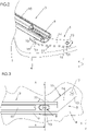
figure 2 est une vue en perspective du dispositif de renfort, monté entre une glissière de siège et un plancher ; - la
figure 3 est une vue de dessus du dispositif de renfort, monté entre une glissière de siège et un plancher ; - la
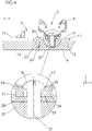
figure 4 est une vue en coupe du dispositif de renfort, monté entre une glissière de siège et un plancher ; - la
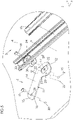
figure 5 est une vue en perspective éclatée du dispositif de renfort, monté entre une glissière de siège et un plancher ; - la
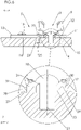
figure 6 est une vue en coupe du dispositif de renfort monté entre une glissière de siège et un plancher, le dispositif de renfort étant représenté selon une variante de réalisation ; - la
figure 7 est une vue en perspective éclatée du dispositif de renfort, monté entre une glissière de siège et un plancher, le dispositif de renfort étant représenté selon une variante de réalisation. - Sur la
figure 1 est représenté un véhicule 1 comprenant un siège 2 pourvu d'une glissière 3, la glissière 3 étant fixée au plancher 4 du véhicule 1, par l'intermédiaire d'un dispositif 5 de renfort. - Le siège 2, représenté partiellement sur la
figure 1 , est une banquette, apte à accueillir plusieurs occupants, comme par exemple une banquette arrière d'un véhicule 1 automobile. - Selon d'autres modes de réalisation, non représenté, le siège 2 est destiné à recevoir une unique personne, comme l'est par exemple un siège avant d'un véhicule 1 automobile.
- De manière non limitative, le véhicule 1 représenté est un véhicule 1 automobile, mais d'autres types de véhicules peuvent être envisagés, par exemple un véhicule maritime, ferroviaire ou aérien.
- On définit par rapport au véhicule 1 un repère orthogonal XYZ comprenant trois axes perpendiculaires deux à deux, à savoir :
- un axe X, définissant une direction longitudinale, horizontale, confondue avec la direction générale de déplacement du véhicule 1,
- un axe Y, définissant une direction transversale, horizontale, qui avec l'axe X définit un plan XY horizontal,
- un axe Z, définissant une direction verticale, perpendiculaire au plan XY horizontal.
- Dans la suite de la description, et en relation au repère défini ci-dessus, les termes "longitudinal" ou "longitudinalement" font référence à une direction confondue avec l'axe X, les termes "transversal" ou "transversalement" font référence à une direction confondue avec l'axe Y, et les termes "vertical" ou "verticalement" font référence à une direction confondue avec l'axe Z. Les termes de position absolue, tels que "avant", "arrière", "haut", "bas", "gauche", "droite", ou relatifs comme "dessus", "supérieur", "dessous", "inférieur" sont définis par rapport au sens de progression normale du véhicule 1, dite "marche avant".
- Comme représenté sur les figures, le véhicule 1 comprend un plancher 4, disposé, de manière non limitative, horizontalement.
- Selon le mode de réalisation représenté sur la
figure 1 , le siège 2 comprend une assise 6 et un dossier 7. Le siège 2 est fixé à une glissière 3, par exemple par l'intermédiaire d'une pluralité de pieds 8. - Tel qu'illustré sur l'ensemble des figures, la glissière 3 comprend une partie 9 fixe, et une partie 10 mobile, la partie 10 mobile étant solidaire des pieds 8 du siège 2, et la partie 9 fixe étant fixée à un support, par exemple le plancher 4 du véhicule 1.
- Selon d'autres modes de réalisation, non représentés, la partie 9 fixe est liée solidairement à des pièces en interface avec le plancher 4.
- La partie 10 mobile est montée coulissante par rapport à la partie 9 fixe, ce qui permet de déplacer le siège 2, par exemple selon une direction longitudinale, vers l'avant ou l'arrière du véhicule 1.
- Le dispositif 5 de renfort comprend une entretoise 11, intercalée entre le plancher 4 et la glissière 3, afin de permettre une bonne transmission des efforts entre la glissière 3 et le plancher 4.
- Comme représenté sur l'ensemble des figures, l'entretoise 11 comprend une partie 12 proximale, une partie 13 distale, la partie 13 distale étant disposée au bout d'un prolongement 14, la partie 13 distale s'étendant au-delà de la glissière 3.
- Avantageusement, la partie 12 proximale et la partie 13 distale sont respectivement munies d'une surface 15 proximale, et d'une surface 16 distale, destinées à entrer en contact avec le plancher 4 du véhicule 1. Aussi, l'entretoise 11 comprend deux surfaces de contact avec le plancher 4. De cette façon, les efforts subis par l'entretoise 11 sont répartis sur ces deux aires de contact.
- Selon d'autres modes de réalisation non représentés, l'entretoise 11 comprend une pluralité de parties 13 distales, chacune d'entre elles étant en contact respectivement avec le plancher 4 par leur surface 15 proximale. Une telle caractéristique permet d'accroître la surface de contact entre l'entretoise 11 et le plancher 4.
- Selon le mode de réalisation représenté, la partie 12 proximale est destinée à être fixée entre la glissière 3 et le plancher 4 du véhicule 1. Comme illustré sur les
figures 4 et5 , la partie 12 proximale est fixée entre la partie 9 fixe de la glissière 3, et le plancher 4. De cette manière, la partie 12 proximale est apte à reprendre les efforts du siège 2 et de la glissière 3, lorsqu'une contrainte, par exemple une contrainte de compression, est appliquée en direction du plancher 4. Autrement dit, la partie 12 proximale est fixée au plancher 4 du véhicule 1, par l'intermédiaire de la pression exercée par la partie 9 fixe de la glissière 3. - Selon le mode de réalisation représenté, le dispositif 5 de renfort comprend au sein de la partie 12 proximale, une ouverture 17 proximale et un moyen d'assemblage, comme une vis 18 d'assemblage. La vis 18 d'assemblage et la partie 12 proximale sont toutes deux avantageusement coaxiales avec une cavité 24, disposée sur la partie 9 fixe de la glissière 3, et un trou 21 fileté, agencé sur le plancher 4 du véhicule 1. De cette manière, la vis 18 d'assemblage est apte à traverser à la fois la cavité 24, et l'ouverture 17 proximale, afin de s'insérer au sein du plancher 4, ce qui offre l'avantage de permettre un montage simple du dispositif 5 de renfort au sein du véhicule 1, comme illustré sur la
figure 5 . - Selon le mode de réalisation représenté, la partie 12 proximale est en contact avec la glissière 3, par l'intermédiaire de la surface opposée à la surface 15 proximale.
- Selon d'autres modes de réalisation, non représentés, la partie 12 proximale n'est pas directement en contact avec la glissière 3, mais avec des pièces d'interface disposées entre la partie 12 proximale et la glissière 3, comme par exemple une rondelle d'appui.
- Comme représenté sur l'ensemble des figures, le dispositif 5 de renfort comprend un pion 22 de centrage, destiné à être inséré au sein d'un orifice 25 agencé dans le plancher 4 du véhicule 1. Un tel pion 22 de centrage permet d'arrêter la rotation du dispositif 5 de renfort, et agit comme détrompeur afin d'éviter les erreurs d'assemblage, lors du montage du dispositif 5 de renfort sur le plancher 4.
- Comme représenté sur les
figures 4 et5 , le pion 22 de centrage 22 est inséré dans l'entretoise 11, par l'intermédiaire d'une ouverture 23 de centrage. - Selon d'autres modes de réalisation, non représentés, le pion 22 de centrage est venu de matière de l'entretoise 11.
- Grâce aux effets conjugués du pion 22 de centrage, du contact plan sur plan des surfaces 15, 16 de l'entretoise 11 sur le plancher 4, de l'effort de compression de la vis 18 d'assemblage, l'entretoise 11 est fixée sur le plancher 4.
- Selon le mode de réalisation représenté, la partie 13 distale comprend une ouverture 26 distale, apte à permettre le passage d'un moyen de fixation, par exemple une vis 19 de fixation destinée à être en insertion dans un alésage 20 taraudé prévu dans le plancher 4. De cette façon, l'entretoise est maintenue en position, et fixée au plancher 4. Le mouvement de la partie 26 distale est arrêté verticalement et horizontalement.
- Avantageusement, la partie 13 distale est solidairement rattachée au plancher 4 du véhicule 1, par exemple en rendant le plancher 4 et la surface 16 distale contraints entre eux en compression. Par ce biais, la partie 16 distale est bloquée en rotation.
- Selon d'autres modes de réalisation, non représentés, le moyen de fixation est une tige filetée, un goujon, ou tout autre type d'assemblage boulonné.
- De préférence, la partie 13 et le plancher 4 sont en liaison encastrement, par exemple grâce à la contrainte de compression entre la partie 13 distale et le moyen de fixation. Autrement dit le plancher 4 et la partie 13 distale ne présentent sensiblement entre eux aucun degré de liberté de mouvement.
- De cette manière, le plancher 4 et la partie 13 distale restent en contact l'un de l'autre, y compris lorsqu'un effort, par exemple une force de séparation conséquente à un choc du véhicule 1 sur un obstacle, tend à les séparer l'un de l'autre. Une telle caractéristique permet de renforcer la fixation de la glissière 3 sur le plancher 4, car l'entretoise 11 comprend une fixation additionnelle sur le plancher 4, en sus de la fixation localisée au sein de la partie 12 proximale. L'effort d'arrachement exercée par le siège 2 et la glissière 3 sur le plancher 4 est ainsi réparti sur deux localisations. Aussi, le plancher 4 subissant des efforts locaux diminués, les risques d'arrachement des points de fixation de la glissière 3 sont minimisés.
- Selon le mode de réalisation représenté, le dispositif 5 de renfort présente une forme allongée et définit une courbure. Une telle entretoise 11 en élongation, outre son encombrement réduit, permet de disposer la partie 13 distale sur des trous préexistant situés au delà du voisinage de l'alésage, ce qui évite de devoir effectuer des perçages supplémentaires sur le plancher 4 du véhicule 1.
- Comme représenté sur la
figure 4 , le dispositif 5 de renfort comprend avantageusement un évidement 27 autour de l'ouverture 17 proximale, l'évidement 27 étant en retrait par rapport à la surface 15 proximale. Ainsi, au moment du montage de la glissière 3 sur l'entretoise 11, la pression exercée par le moyen de fixation entraîne une poussée de la partie 9 fixe de la glissière 3 sur l'entretoise 11, ce qui occasionne une déformation de l'évidement 27 de l'entretoise 11. En d'autres termes, l'entretoise 11 présente une zone 28 déformable accrue au voisinage de l'évidement 27, causée par l'amincissement de matière de l'entretoise localisée au droit de l'évidement 27. - Selon le mode de réalisation représenté, le véhicule 1 comprend un siège 2 muni d'un dispositif 5 de renfort tel que précédemment décrit. Comme représenté sur la
figure 5 , la partie 9 fixe est, par exemple munie sur sa face 29 inférieure d'une cale 30 de fixation, la cale 30 présente une lumière 33, destinée au passage de la vis 18 d'assemblage. En général, la glissière 3 est ancrée au véhicule 1 par deux cales 30 de fixation. - Selon d'autres modes de réalisation, non représentés, les cales 30 sont venues de matière de la partie 9 fixe.
- Comme représenté sur la
figure 5 , la partie 12 proximale comprend sur la surface opposée à la surface 15 proximale un trou 32, présentant un contour 31. Le trou 32 présente avantageusement une section transversale ayant une forme complémentaire à la section transversale de la cale 30 de fixation de la glissière 3. Autrement dit, la forme de l'ouverture est identique à la forme du contour 31. Le trou 32 est ainsi destiné à permettre de recevoir la cale 30 de fixation. De cette façon, la mise en position de la glissière 3 sur l'entretoise 11 est guidée par le trou 32, ce qui facilite le montage de la glissière 3 sur le dispositif 5 de renfort. - Selon une variante du mode de réalisation, représentée
figure 6 etfigure 7 , le trou 32 est débouchant, autrement dit la cale 30 est directement en contact avec le plancher du véhicule 1. La reprise d'effort a lieu sur les bords du trou 32, plus précisément au voisinage du contour 31, le trou 32 est alors confondu avec l'ouverture 17 proximale. La reprise d'effort a lieu autour du trou 32, au voisinage du contour. Comme représentéfigure 6 , la zone à déformabilité accrue 28 est préférentiellement localisée autour du trou 32, et est par exemple formée par un évidement 27 réalisé au voisinage du bord du trou 32. - Le dispositif 5 de renfort tel que décrit ci-dessus présente l'avantage d'être escamotable de la structure du siège 2, et de la structure de la glissière 3.
- Le dispositif 5 de renfort offre des facilités de montage. L'opération de montage du dispositif 5 de renfort sur le plancher 4 peut, en effet, être réalisée séparément de l'opération de montage du siège 2 et de la glissière 3 sur le plancher 4 du véhicule 1. La simplicité de montage permet d'améliorer l'ergonomie des mouvements du monteur en usine.
- Etant indépendant du siège 2, le dispositif 5 de renfort offre également l'avantage de ne pas alourdir le siège 2, notamment dans le cas de banquettes arrière coulissantes.
- Le dispositif 5 de renfort ne compromet pas non plus l'encombrement du siège 2, ce qui permet d'optimiser l'emballage du siège 2 et son stockage en entrepôt.
- Le dispositif 5 de renfort est par ailleurs facilement adaptable aux sièges 2 et glissières 3 préexistants, les modifications à apporter étant mineures, ce qui offre au fabriquant une flexibilité quant à l'utilisation ou non du dispositif 5 de renfort sur les sièges 2. Par exemple, pour une application dans l'automobile, la présence ou non du dispositif 5 de renfort peut être uniquement dictée par les impératifs de sécurité, liés aux résultats des crashs tests.
- Enfin, le dispositif 5 de renfort est simple, peu couteux à réaliser et compatible avec une utilisation en grande série.
Claims (7)
- Véhicule (1) comprenant un dispositif (5) de renfort agencé entre une glissière (3) d'un siège (2) et un plancher (4) de véhicule (1), le dispositif (5) de renfort comprenant une entretoise (11) incluant une partie (12) proximale destinée à être fixée entre la glissière (3) et le plancher (4), et une partie (13) distale, en prolongement de la partie (12) proximale, la partie (13) distale s'étendant au-delà de la glissière (3), la partie (13) distale étant destinée à être fixée sur le plancher (4), la glissière (3) étant destinée à être fixée sur le plancher (4) du véhicule (1), une cale (30) de fixation faisant saillie de la glissière (3), la partie (12) proximale du dispositif (5) de renfort comprenant un trou (32) destiné à recevoir ladite cale (30) de fixation, le dispositif (5) de renfort étant caractérisé en ce que la partie (12) proximale est fixée au plancher (4) du véhicule (1), par l'intermédiaire de la pression exercée par la partie (9) fixe de la glissière (3).
- Véhicule (1) comprenant un dispositif (5) de renfort selon la revendication 1, caractérisé en ce que la partie distale (13) est destinée à former une liaison encastrement avec le plancher (4).
- Véhicule (1) comprenant un dispositif (5) de renfort selon la revendication 1 ou 2, caractérisé en ce qu'il comprend une ouverture (26) distale, disposée sur la partie (13) distale, et une vis (19) de fixation, l'ouverture (26) distale étant apte à permettre le passage de la vis (19) de fixation.
- Véhicule (1) comprenant un dispositif (5) de renfort selon l'une quelconque des revendications précédentes, caractérisé en ce qu'il comprend un pion (22) de centrage, le pion (22) de centrage étant apte à être inséré dans un orifice (25) agencé dans le plancher (4) du véhicule (1).
- Véhicule (1) comprenant un dispositif (5) de renfort selon l'une quelconque des revendications précédentes, caractérisé en ce qu'il comprend plusieurs parties (13) distales.
- Véhicule (1) comprenant un dispositif (5) de renfort selon l'une quelconque des revendications précédentes, caractérisé en ce qu'il comprend une ouverture (17) proximale, disposée sur la partie (12) proximale, et une vis (18) d'assemblage, la vis (18) d'assemblage s'insérant au sein de l'ouverture (17) proximale.
- Véhicule (1) comprenant un dispositif (5) de renfort selon la revendication 6, caractérisé en ce qu'il comprend un évidement (27) disposé autour de l'ouverture (17) proximale, l'évidement (27) formant une zone (28) déformable sur l'entretoise (11).
Applications Claiming Priority (2)
| Application Number | Priority Date | Filing Date | Title |
|---|---|---|---|
| FR1661286A FR3058942B1 (fr) | 2016-11-21 | 2016-11-21 | Dispositif de renfort amovible de la glissiere d’un siege d’un vehicule sur un support |
| PCT/FR2017/053153 WO2018091845A1 (fr) | 2016-11-21 | 2017-11-17 | Dispositif de renfort amovible de la glissiere d'un siege d'un vehicule sur un support |
Publications (2)
| Publication Number | Publication Date |
|---|---|
| EP3541656A1 EP3541656A1 (fr) | 2019-09-25 |
| EP3541656B1 true EP3541656B1 (fr) | 2022-12-28 |
Family
ID=57755344
Family Applications (1)
| Application Number | Title | Priority Date | Filing Date |
|---|---|---|---|
| EP17804257.8A Active EP3541656B1 (fr) | 2016-11-21 | 2017-11-17 | Dispositif de renfort amovible de la glissiere d'un siege d'un vehicule sur un support |
Country Status (4)
| Country | Link |
|---|---|
| EP (1) | EP3541656B1 (fr) |
| CN (1) | CN109982891B (fr) |
| FR (1) | FR3058942B1 (fr) |
| WO (1) | WO2018091845A1 (fr) |
Families Citing this family (1)
| Publication number | Priority date | Publication date | Assignee | Title |
|---|---|---|---|---|
| FR3131714A1 (fr) * | 2022-01-10 | 2023-07-14 | Faurecia Sièges d'Automobile | Glissière pour siège de véhicule, siège de véhicule comportant une telle glissière, ensemble intérieur de véhicule comportant un tel siège et procédé de fabrication |
Family Cites Families (12)
| Publication number | Priority date | Publication date | Assignee | Title |
|---|---|---|---|---|
| JPH10175469A (ja) * | 1996-12-17 | 1998-06-30 | Aisin Seiki Co Ltd | 車両用シート装置 |
| CN101410272B (zh) * | 2006-03-31 | 2011-06-22 | 英提尔汽车公司 | 折叠式头枕 |
| FR2909046B1 (fr) * | 2006-11-29 | 2009-08-21 | Peugeot Citroen Automobiles Sa | Ensemble interieur de vehicule automobile, armature de siege et procede de montage associes. |
| CN201401471Y (zh) * | 2009-03-03 | 2010-02-10 | 超化公司 | 一种波形活压预紧碟簧 |
| JP5690093B2 (ja) * | 2010-07-29 | 2015-03-25 | ジョンソン コントロールズ テクノロジー カンパニーJohnson Controls Technology Company | 乗り物用シート構造 |
| FR2980157B1 (fr) * | 2011-09-16 | 2013-09-27 | Faurecia Sieges Automobile | Entretoise de fixation pour sieges de vehicules, glissieres comportant une telle entretoise, siege comportant une telle glissiere et procede de fabrication |
| JP6016056B2 (ja) * | 2012-03-23 | 2016-10-26 | いすゞ自動車株式会社 | 車両のシートレール取付構造 |
| JP5930304B2 (ja) * | 2012-08-07 | 2016-06-08 | スズキ株式会社 | 車両用シート |
| CN104057844B (zh) * | 2013-03-22 | 2016-05-04 | 长春博泽汽车部件有限公司 | 校正座椅导轨上的孔图案的地毯垫片和座椅导轨安装组件 |
| FR3006253B1 (fr) | 2013-06-04 | 2015-05-29 | Peugeot Citroen Automobiles Sa | Dispositif de fixation de glissiere |
| CN203463432U (zh) * | 2013-09-13 | 2014-03-05 | 广东欧科空调制冷有限公司 | 一种钣金件的连接结构 |
| CN205298221U (zh) * | 2016-01-27 | 2016-06-08 | 廊坊双飞碟簧有限公司 | 碟形抗振防松垫圈 |
-
2016
- 2016-11-21 FR FR1661286A patent/FR3058942B1/fr not_active Expired - Fee Related
-
2017
- 2017-11-17 CN CN201780072098.3A patent/CN109982891B/zh not_active Expired - Fee Related
- 2017-11-17 EP EP17804257.8A patent/EP3541656B1/fr active Active
- 2017-11-17 WO PCT/FR2017/053153 patent/WO2018091845A1/fr not_active Ceased
Also Published As
| Publication number | Publication date |
|---|---|
| CN109982891B (zh) | 2022-06-07 |
| FR3058942B1 (fr) | 2021-06-11 |
| EP3541656A1 (fr) | 2019-09-25 |
| CN109982891A (zh) | 2019-07-05 |
| FR3058942A1 (fr) | 2018-05-25 |
| WO2018091845A1 (fr) | 2018-05-24 |
Similar Documents
| Publication | Publication Date | Title |
|---|---|---|
| EP2303631B1 (fr) | Siege pour vehicule blinde | |
| EP2586648B1 (fr) | Système comprenant une glissière de siège de véhicule automobile et un support destiné a y etre fixé et procédé de fabrication d'un tel système | |
| WO2017129692A1 (fr) | Butée d'arrêt pour siège d'avion | |
| EP3541656B1 (fr) | Dispositif de renfort amovible de la glissiere d'un siege d'un vehicule sur un support | |
| FR3074107A1 (fr) | Siege automobile rotatif comprenant un organe anti-arrachement et vehicule automobile comprenant un tel siege | |
| FR3019780A1 (fr) | Vehicule automobile equipe d’une banquette arriere allegee. | |
| EP1826059B1 (fr) | Assemblage d'une tige d'appui-tête sur un siège au moyen d'une gaine pourvue de trois ergots | |
| FR3123841A1 (fr) | Dispositif de support électrique pour déplacer et orienter un objet dans un véhicule | |
| EP3953239B1 (fr) | Dispositif de renfort d'une traverse de poste de conduite d'un véhicule automobile | |
| EP4072927B1 (fr) | Dispositif de renfort d'une traverse de poste de conduite d'un véhicule automobile | |
| FR2929564A1 (fr) | Siege de vehicule automobile | |
| EP4436874B1 (fr) | Système de fixation de ceinture pour un siège à assise mobile | |
| FR3014379A1 (fr) | Dossier de siege de vehicule et siege comportant un tel dossier | |
| FR3078925A1 (fr) | Siege pour vehicule automobile | |
| FR3129634A1 (fr) | Système de réglage de position de siège de véhicule comportant un mécanisme anti-déformation destiné à éviter une déformation en cas d’accident | |
| EP4347400A1 (fr) | Assise de siege, notamment de siege d'avion, munie d'une zone de degagement pour le bassin | |
| FR3063258A1 (fr) | Bague destinee au maintien d'un appui tete escamotable, appui tete comprenant une telle bague, siege comprenant un tel appui tete et vehicule comprenant un tel siege | |
| EP4347399A1 (fr) | Assise de siege, notamment de siege d'avion, munie d'un tube absorbeur d'energie cinetique | |
| FR2887501A1 (fr) | Siege pour vehicule automobile | |
| FR3141650A1 (fr) | Dispositif de contrôle à liaison rigide incurvée, pour un siège à hauteur réglable d’un véhicule | |
| FR3114063A1 (fr) | Système de cloison mobile destiné à séparer deux espaces d’un véhicule automobile. | |
| FR3080806A1 (fr) | Module d'ancrage d'un equipement automobile, glissiere d'ancrage et ensemble d'ancrage | |
| FR2961137A1 (fr) | Siege de vehicule automobile | |
| FR3080804A1 (fr) | Module d'ancrage | |
| EP3408177A1 (fr) | Butée d'arrêt pour siège d'avion |
Legal Events
| Date | Code | Title | Description |
|---|---|---|---|
| STAA | Information on the status of an ep patent application or granted ep patent |
Free format text: STATUS: UNKNOWN |
|
| STAA | Information on the status of an ep patent application or granted ep patent |
Free format text: STATUS: THE INTERNATIONAL PUBLICATION HAS BEEN MADE |
|
| PUAI | Public reference made under article 153(3) epc to a published international application that has entered the european phase |
Free format text: ORIGINAL CODE: 0009012 |
|
| STAA | Information on the status of an ep patent application or granted ep patent |
Free format text: STATUS: REQUEST FOR EXAMINATION WAS MADE |
|
| 17P | Request for examination filed |
Effective date: 20190409 |
|
| AK | Designated contracting states |
Kind code of ref document: A1 Designated state(s): AL AT BE BG CH CY CZ DE DK EE ES FI FR GB GR HR HU IE IS IT LI LT LU LV MC MK MT NL NO PL PT RO RS SE SI SK SM TR |
|
| AX | Request for extension of the european patent |
Extension state: BA ME |
|
| DAV | Request for validation of the european patent (deleted) | ||
| DAX | Request for extension of the european patent (deleted) | ||
| STAA | Information on the status of an ep patent application or granted ep patent |
Free format text: STATUS: EXAMINATION IS IN PROGRESS |
|
| RAP1 | Party data changed (applicant data changed or rights of an application transferred) |
Owner name: PSA AUTOMOBILES SA |
|
| 17Q | First examination report despatched |
Effective date: 20201020 |
|
| GRAP | Despatch of communication of intention to grant a patent |
Free format text: ORIGINAL CODE: EPIDOSNIGR1 |
|
| STAA | Information on the status of an ep patent application or granted ep patent |
Free format text: STATUS: GRANT OF PATENT IS INTENDED |
|
| INTG | Intention to grant announced |
Effective date: 20220817 |
|
| GRAS | Grant fee paid |
Free format text: ORIGINAL CODE: EPIDOSNIGR3 |
|
| GRAA | (expected) grant |
Free format text: ORIGINAL CODE: 0009210 |
|
| STAA | Information on the status of an ep patent application or granted ep patent |
Free format text: STATUS: THE PATENT HAS BEEN GRANTED |
|
| AK | Designated contracting states |
Kind code of ref document: B1 Designated state(s): AL AT BE BG CH CY CZ DE DK EE ES FI FR GB GR HR HU IE IS IT LI LT LU LV MC MK MT NL NO PL PT RO RS SE SI SK SM TR |
|
| REG | Reference to a national code |
Ref country code: GB Ref legal event code: FG4D Free format text: NOT ENGLISH |
|
| REG | Reference to a national code |
Ref country code: CH Ref legal event code: EP |
|
| REG | Reference to a national code |
Ref country code: DE Ref legal event code: R096 Ref document number: 602017065060 Country of ref document: DE |
|
| REG | Reference to a national code |
Ref country code: AT Ref legal event code: REF Ref document number: 1540270 Country of ref document: AT Kind code of ref document: T Effective date: 20230115 |
|
| REG | Reference to a national code |
Ref country code: IE Ref legal event code: FG4D Free format text: LANGUAGE OF EP DOCUMENT: FRENCH |
|
| REG | Reference to a national code |
Ref country code: DE Ref legal event code: R084 Ref document number: 602017065060 Country of ref document: DE |
|
| REG | Reference to a national code |
Ref country code: GB Ref legal event code: 746 Effective date: 20230213 |
|
| REG | Reference to a national code |
Ref country code: LT Ref legal event code: MG9D |
|
| PG25 | Lapsed in a contracting state [announced via postgrant information from national office to epo] |
Ref country code: SE Free format text: LAPSE BECAUSE OF FAILURE TO SUBMIT A TRANSLATION OF THE DESCRIPTION OR TO PAY THE FEE WITHIN THE PRESCRIBED TIME-LIMIT Effective date: 20221228 Ref country code: NO Free format text: LAPSE BECAUSE OF FAILURE TO SUBMIT A TRANSLATION OF THE DESCRIPTION OR TO PAY THE FEE WITHIN THE PRESCRIBED TIME-LIMIT Effective date: 20230328 Ref country code: LT Free format text: LAPSE BECAUSE OF FAILURE TO SUBMIT A TRANSLATION OF THE DESCRIPTION OR TO PAY THE FEE WITHIN THE PRESCRIBED TIME-LIMIT Effective date: 20221228 Ref country code: FI Free format text: LAPSE BECAUSE OF FAILURE TO SUBMIT A TRANSLATION OF THE DESCRIPTION OR TO PAY THE FEE WITHIN THE PRESCRIBED TIME-LIMIT Effective date: 20221228 |
|
| REG | Reference to a national code |
Ref country code: NL Ref legal event code: MP Effective date: 20221228 |
|
| REG | Reference to a national code |
Ref country code: AT Ref legal event code: MK05 Ref document number: 1540270 Country of ref document: AT Kind code of ref document: T Effective date: 20221228 |
|
| PG25 | Lapsed in a contracting state [announced via postgrant information from national office to epo] |
Ref country code: RS Free format text: LAPSE BECAUSE OF FAILURE TO SUBMIT A TRANSLATION OF THE DESCRIPTION OR TO PAY THE FEE WITHIN THE PRESCRIBED TIME-LIMIT Effective date: 20221228 Ref country code: LV Free format text: LAPSE BECAUSE OF FAILURE TO SUBMIT A TRANSLATION OF THE DESCRIPTION OR TO PAY THE FEE WITHIN THE PRESCRIBED TIME-LIMIT Effective date: 20221228 Ref country code: HR Free format text: LAPSE BECAUSE OF FAILURE TO SUBMIT A TRANSLATION OF THE DESCRIPTION OR TO PAY THE FEE WITHIN THE PRESCRIBED TIME-LIMIT Effective date: 20221228 Ref country code: GR Free format text: LAPSE BECAUSE OF FAILURE TO SUBMIT A TRANSLATION OF THE DESCRIPTION OR TO PAY THE FEE WITHIN THE PRESCRIBED TIME-LIMIT Effective date: 20230329 |
|
| PG25 | Lapsed in a contracting state [announced via postgrant information from national office to epo] |
Ref country code: NL Free format text: LAPSE BECAUSE OF FAILURE TO SUBMIT A TRANSLATION OF THE DESCRIPTION OR TO PAY THE FEE WITHIN THE PRESCRIBED TIME-LIMIT Effective date: 20221228 |
|
| PG25 | Lapsed in a contracting state [announced via postgrant information from national office to epo] |
Ref country code: SM Free format text: LAPSE BECAUSE OF FAILURE TO SUBMIT A TRANSLATION OF THE DESCRIPTION OR TO PAY THE FEE WITHIN THE PRESCRIBED TIME-LIMIT Effective date: 20221228 Ref country code: RO Free format text: LAPSE BECAUSE OF FAILURE TO SUBMIT A TRANSLATION OF THE DESCRIPTION OR TO PAY THE FEE WITHIN THE PRESCRIBED TIME-LIMIT Effective date: 20221228 Ref country code: PT Free format text: LAPSE BECAUSE OF FAILURE TO SUBMIT A TRANSLATION OF THE DESCRIPTION OR TO PAY THE FEE WITHIN THE PRESCRIBED TIME-LIMIT Effective date: 20230428 Ref country code: ES Free format text: LAPSE BECAUSE OF FAILURE TO SUBMIT A TRANSLATION OF THE DESCRIPTION OR TO PAY THE FEE WITHIN THE PRESCRIBED TIME-LIMIT Effective date: 20221228 Ref country code: EE Free format text: LAPSE BECAUSE OF FAILURE TO SUBMIT A TRANSLATION OF THE DESCRIPTION OR TO PAY THE FEE WITHIN THE PRESCRIBED TIME-LIMIT Effective date: 20221228 Ref country code: CZ Free format text: LAPSE BECAUSE OF FAILURE TO SUBMIT A TRANSLATION OF THE DESCRIPTION OR TO PAY THE FEE WITHIN THE PRESCRIBED TIME-LIMIT Effective date: 20221228 Ref country code: AT Free format text: LAPSE BECAUSE OF FAILURE TO SUBMIT A TRANSLATION OF THE DESCRIPTION OR TO PAY THE FEE WITHIN THE PRESCRIBED TIME-LIMIT Effective date: 20221228 |
|
| PG25 | Lapsed in a contracting state [announced via postgrant information from national office to epo] |
Ref country code: SK Free format text: LAPSE BECAUSE OF FAILURE TO SUBMIT A TRANSLATION OF THE DESCRIPTION OR TO PAY THE FEE WITHIN THE PRESCRIBED TIME-LIMIT Effective date: 20221228 Ref country code: PL Free format text: LAPSE BECAUSE OF FAILURE TO SUBMIT A TRANSLATION OF THE DESCRIPTION OR TO PAY THE FEE WITHIN THE PRESCRIBED TIME-LIMIT Effective date: 20221228 Ref country code: IS Free format text: LAPSE BECAUSE OF FAILURE TO SUBMIT A TRANSLATION OF THE DESCRIPTION OR TO PAY THE FEE WITHIN THE PRESCRIBED TIME-LIMIT Effective date: 20230428 Ref country code: AL Free format text: LAPSE BECAUSE OF FAILURE TO SUBMIT A TRANSLATION OF THE DESCRIPTION OR TO PAY THE FEE WITHIN THE PRESCRIBED TIME-LIMIT Effective date: 20221228 |
|
| REG | Reference to a national code |
Ref country code: DE Ref legal event code: R097 Ref document number: 602017065060 Country of ref document: DE |
|
| PG25 | Lapsed in a contracting state [announced via postgrant information from national office to epo] |
Ref country code: DK Free format text: LAPSE BECAUSE OF FAILURE TO SUBMIT A TRANSLATION OF THE DESCRIPTION OR TO PAY THE FEE WITHIN THE PRESCRIBED TIME-LIMIT Effective date: 20221228 |
|
| PLBE | No opposition filed within time limit |
Free format text: ORIGINAL CODE: 0009261 |
|
| STAA | Information on the status of an ep patent application or granted ep patent |
Free format text: STATUS: NO OPPOSITION FILED WITHIN TIME LIMIT |
|
| 26N | No opposition filed |
Effective date: 20230929 |
|
| PGFP | Annual fee paid to national office [announced via postgrant information from national office to epo] |
Ref country code: GB Payment date: 20231019 Year of fee payment: 7 |
|
| PG25 | Lapsed in a contracting state [announced via postgrant information from national office to epo] |
Ref country code: SI Free format text: LAPSE BECAUSE OF FAILURE TO SUBMIT A TRANSLATION OF THE DESCRIPTION OR TO PAY THE FEE WITHIN THE PRESCRIBED TIME-LIMIT Effective date: 20221228 |
|
| PGFP | Annual fee paid to national office [announced via postgrant information from national office to epo] |
Ref country code: FR Payment date: 20231019 Year of fee payment: 7 Ref country code: DE Payment date: 20231019 Year of fee payment: 7 |
|
| REG | Reference to a national code |
Ref country code: DE Ref legal event code: R081 Ref document number: 602017065060 Country of ref document: DE Owner name: STELLANTIS AUTO SAS, FR Free format text: FORMER OWNER: PSA AUTOMOBILES SA, POISSY, FR |
|
| PG25 | Lapsed in a contracting state [announced via postgrant information from national office to epo] |
Ref country code: IT Free format text: LAPSE BECAUSE OF FAILURE TO SUBMIT A TRANSLATION OF THE DESCRIPTION OR TO PAY THE FEE WITHIN THE PRESCRIBED TIME-LIMIT Effective date: 20221228 |
|
| REG | Reference to a national code |
Ref country code: CH Ref legal event code: PL |
|
| PG25 | Lapsed in a contracting state [announced via postgrant information from national office to epo] |
Ref country code: MC Free format text: LAPSE BECAUSE OF FAILURE TO SUBMIT A TRANSLATION OF THE DESCRIPTION OR TO PAY THE FEE WITHIN THE PRESCRIBED TIME-LIMIT Effective date: 20221228 |
|
| PG25 | Lapsed in a contracting state [announced via postgrant information from national office to epo] |
Ref country code: LU Free format text: LAPSE BECAUSE OF NON-PAYMENT OF DUE FEES Effective date: 20231117 |
|
| PG25 | Lapsed in a contracting state [announced via postgrant information from national office to epo] |
Ref country code: CH Free format text: LAPSE BECAUSE OF NON-PAYMENT OF DUE FEES Effective date: 20231130 |
|
| PG25 | Lapsed in a contracting state [announced via postgrant information from national office to epo] |
Ref country code: MC Free format text: LAPSE BECAUSE OF FAILURE TO SUBMIT A TRANSLATION OF THE DESCRIPTION OR TO PAY THE FEE WITHIN THE PRESCRIBED TIME-LIMIT Effective date: 20221228 Ref country code: LU Free format text: LAPSE BECAUSE OF NON-PAYMENT OF DUE FEES Effective date: 20231117 Ref country code: CH Free format text: LAPSE BECAUSE OF NON-PAYMENT OF DUE FEES Effective date: 20231130 |
|
| REG | Reference to a national code |
Ref country code: BE Ref legal event code: MM Effective date: 20231130 |
|
| REG | Reference to a national code |
Ref country code: IE Ref legal event code: MM4A |
|
| PG25 | Lapsed in a contracting state [announced via postgrant information from national office to epo] |
Ref country code: IE Free format text: LAPSE BECAUSE OF NON-PAYMENT OF DUE FEES Effective date: 20231117 |
|
| PG25 | Lapsed in a contracting state [announced via postgrant information from national office to epo] |
Ref country code: BE Free format text: LAPSE BECAUSE OF NON-PAYMENT OF DUE FEES Effective date: 20231130 |
|
| PG25 | Lapsed in a contracting state [announced via postgrant information from national office to epo] |
Ref country code: IE Free format text: LAPSE BECAUSE OF NON-PAYMENT OF DUE FEES Effective date: 20231117 Ref country code: BE Free format text: LAPSE BECAUSE OF NON-PAYMENT OF DUE FEES Effective date: 20231130 |
|
| PG25 | Lapsed in a contracting state [announced via postgrant information from national office to epo] |
Ref country code: BG Free format text: LAPSE BECAUSE OF FAILURE TO SUBMIT A TRANSLATION OF THE DESCRIPTION OR TO PAY THE FEE WITHIN THE PRESCRIBED TIME-LIMIT Effective date: 20221228 |
|
| PG25 | Lapsed in a contracting state [announced via postgrant information from national office to epo] |
Ref country code: BG Free format text: LAPSE BECAUSE OF FAILURE TO SUBMIT A TRANSLATION OF THE DESCRIPTION OR TO PAY THE FEE WITHIN THE PRESCRIBED TIME-LIMIT Effective date: 20221228 |
|
| REG | Reference to a national code |
Ref country code: DE Ref legal event code: R119 Ref document number: 602017065060 Country of ref document: DE |
|
| GBPC | Gb: european patent ceased through non-payment of renewal fee |
Effective date: 20241117 |
|
| PG25 | Lapsed in a contracting state [announced via postgrant information from national office to epo] |
Ref country code: CY Free format text: LAPSE BECAUSE OF FAILURE TO SUBMIT A TRANSLATION OF THE DESCRIPTION OR TO PAY THE FEE WITHIN THE PRESCRIBED TIME-LIMIT; INVALID AB INITIO Effective date: 20171117 |
|
| PG25 | Lapsed in a contracting state [announced via postgrant information from national office to epo] |
Ref country code: HU Free format text: LAPSE BECAUSE OF FAILURE TO SUBMIT A TRANSLATION OF THE DESCRIPTION OR TO PAY THE FEE WITHIN THE PRESCRIBED TIME-LIMIT; INVALID AB INITIO Effective date: 20171117 |
|
| PG25 | Lapsed in a contracting state [announced via postgrant information from national office to epo] |
Ref country code: DE Free format text: LAPSE BECAUSE OF NON-PAYMENT OF DUE FEES Effective date: 20250603 |
|
| PG25 | Lapsed in a contracting state [announced via postgrant information from national office to epo] |
Ref country code: GB Free format text: LAPSE BECAUSE OF NON-PAYMENT OF DUE FEES Effective date: 20241117 |
|
| PG25 | Lapsed in a contracting state [announced via postgrant information from national office to epo] |
Ref country code: FR Free format text: LAPSE BECAUSE OF NON-PAYMENT OF DUE FEES Effective date: 20241130 |
|
| PG25 | Lapsed in a contracting state [announced via postgrant information from national office to epo] |
Ref country code: TR Free format text: LAPSE BECAUSE OF FAILURE TO SUBMIT A TRANSLATION OF THE DESCRIPTION OR TO PAY THE FEE WITHIN THE PRESCRIBED TIME-LIMIT Effective date: 20221228 |