EP3541645B1 - Condenser for an air conditioner, in particular for a motor vehicle - Google Patents
Condenser for an air conditioner, in particular for a motor vehicle Download PDFInfo
- Publication number
- EP3541645B1 EP3541645B1 EP17801450.2A EP17801450A EP3541645B1 EP 3541645 B1 EP3541645 B1 EP 3541645B1 EP 17801450 A EP17801450 A EP 17801450A EP 3541645 B1 EP3541645 B1 EP 3541645B1
- Authority
- EP
- European Patent Office
- Prior art keywords
- coolant
- insert
- condenser
- collecting tube
- condenser according
- Prior art date
- Legal status (The legal status is an assumption and is not a legal conclusion. Google has not performed a legal analysis and makes no representation as to the accuracy of the status listed.)
- Active
Links
Images



Classifications
-
- F—MECHANICAL ENGINEERING; LIGHTING; HEATING; WEAPONS; BLASTING
- F28—HEAT EXCHANGE IN GENERAL
- F28D—HEAT-EXCHANGE APPARATUS, NOT PROVIDED FOR IN ANOTHER SUBCLASS, IN WHICH THE HEAT-EXCHANGE MEDIA DO NOT COME INTO DIRECT CONTACT
- F28D1/00—Heat-exchange apparatus having stationary conduit assemblies for one heat-exchange medium only, the media being in contact with different sides of the conduit wall, in which the other heat-exchange medium is a large body of fluid, e.g. domestic or motor car radiators
- F28D1/02—Heat-exchange apparatus having stationary conduit assemblies for one heat-exchange medium only, the media being in contact with different sides of the conduit wall, in which the other heat-exchange medium is a large body of fluid, e.g. domestic or motor car radiators with heat-exchange conduits immersed in the body of fluid
- F28D1/04—Heat-exchange apparatus having stationary conduit assemblies for one heat-exchange medium only, the media being in contact with different sides of the conduit wall, in which the other heat-exchange medium is a large body of fluid, e.g. domestic or motor car radiators with heat-exchange conduits immersed in the body of fluid with tubular conduits
- F28D1/053—Heat-exchange apparatus having stationary conduit assemblies for one heat-exchange medium only, the media being in contact with different sides of the conduit wall, in which the other heat-exchange medium is a large body of fluid, e.g. domestic or motor car radiators with heat-exchange conduits immersed in the body of fluid with tubular conduits the conduits being straight
- F28D1/0535—Heat-exchange apparatus having stationary conduit assemblies for one heat-exchange medium only, the media being in contact with different sides of the conduit wall, in which the other heat-exchange medium is a large body of fluid, e.g. domestic or motor car radiators with heat-exchange conduits immersed in the body of fluid with tubular conduits the conduits being straight the conduits having a non-circular cross-section
- F28D1/05366—Assemblies of conduits connected to common headers, e.g. core type radiators
- F28D1/05375—Assemblies of conduits connected to common headers, e.g. core type radiators with particular pattern of flow, e.g. change of flow direction
-
- B—PERFORMING OPERATIONS; TRANSPORTING
- B60—VEHICLES IN GENERAL
- B60H—ARRANGEMENTS OF HEATING, COOLING, VENTILATING OR OTHER AIR-TREATING DEVICES SPECIALLY ADAPTED FOR PASSENGER OR GOODS SPACES OF VEHICLES
- B60H1/00—Heating, cooling or ventilating devices
- B60H1/00321—Heat exchangers for air-conditioning devices
- B60H1/00335—Heat exchangers for air-conditioning devices of the gas-air type
-
- F—MECHANICAL ENGINEERING; LIGHTING; HEATING; WEAPONS; BLASTING
- F25—REFRIGERATION OR COOLING; COMBINED HEATING AND REFRIGERATION SYSTEMS; HEAT PUMP SYSTEMS; MANUFACTURE OR STORAGE OF ICE; LIQUEFACTION SOLIDIFICATION OF GASES
- F25B—REFRIGERATION MACHINES, PLANTS OR SYSTEMS; COMBINED HEATING AND REFRIGERATION SYSTEMS; HEAT PUMP SYSTEMS
- F25B39/00—Evaporators; Condensers
- F25B39/04—Condensers
-
- F—MECHANICAL ENGINEERING; LIGHTING; HEATING; WEAPONS; BLASTING
- F28—HEAT EXCHANGE IN GENERAL
- F28F—DETAILS OF HEAT-EXCHANGE AND HEAT-TRANSFER APPARATUS, OF GENERAL APPLICATION
- F28F9/00—Casings; Header boxes; Auxiliary supports for elements; Auxiliary members within casings
- F28F9/02—Header boxes; End plates
- F28F9/0202—Header boxes having their inner space divided by partitions
- F28F9/0204—Header boxes having their inner space divided by partitions for elongated header box, e.g. with transversal and longitudinal partitions
- F28F9/0214—Header boxes having their inner space divided by partitions for elongated header box, e.g. with transversal and longitudinal partitions having only longitudinal partitions
- F28F9/0217—Header boxes having their inner space divided by partitions for elongated header box, e.g. with transversal and longitudinal partitions having only longitudinal partitions the partitions being separate elements attached to header boxes
-
- F—MECHANICAL ENGINEERING; LIGHTING; HEATING; WEAPONS; BLASTING
- F28—HEAT EXCHANGE IN GENERAL
- F28F—DETAILS OF HEAT-EXCHANGE AND HEAT-TRANSFER APPARATUS, OF GENERAL APPLICATION
- F28F9/00—Casings; Header boxes; Auxiliary supports for elements; Auxiliary members within casings
- F28F9/02—Header boxes; End plates
- F28F9/0246—Arrangements for connecting header boxes with flow lines
-
- F—MECHANICAL ENGINEERING; LIGHTING; HEATING; WEAPONS; BLASTING
- F28—HEAT EXCHANGE IN GENERAL
- F28F—DETAILS OF HEAT-EXCHANGE AND HEAT-TRANSFER APPARATUS, OF GENERAL APPLICATION
- F28F9/00—Casings; Header boxes; Auxiliary supports for elements; Auxiliary members within casings
- F28F9/02—Header boxes; End plates
- F28F9/026—Header boxes; End plates with static flow control means, e.g. with means for uniformly distributing heat exchange media into conduits
-
- F—MECHANICAL ENGINEERING; LIGHTING; HEATING; WEAPONS; BLASTING
- F25—REFRIGERATION OR COOLING; COMBINED HEATING AND REFRIGERATION SYSTEMS; HEAT PUMP SYSTEMS; MANUFACTURE OR STORAGE OF ICE; LIQUEFACTION SOLIDIFICATION OF GASES
- F25B—REFRIGERATION MACHINES, PLANTS OR SYSTEMS; COMBINED HEATING AND REFRIGERATION SYSTEMS; HEAT PUMP SYSTEMS
- F25B2339/00—Details of evaporators; Details of condensers
- F25B2339/04—Details of condensers
- F25B2339/044—Condensers with an integrated receiver
- F25B2339/0441—Condensers with an integrated receiver containing a drier or a filter
-
- F—MECHANICAL ENGINEERING; LIGHTING; HEATING; WEAPONS; BLASTING
- F28—HEAT EXCHANGE IN GENERAL
- F28D—HEAT-EXCHANGE APPARATUS, NOT PROVIDED FOR IN ANOTHER SUBCLASS, IN WHICH THE HEAT-EXCHANGE MEDIA DO NOT COME INTO DIRECT CONTACT
- F28D21/00—Heat-exchange apparatus not covered by any of the groups F28D1/00 - F28D20/00
- F28D2021/0019—Other heat exchangers for particular applications; Heat exchange systems not otherwise provided for
- F28D2021/008—Other heat exchangers for particular applications; Heat exchange systems not otherwise provided for for vehicles
- F28D2021/0084—Condensers
-
- F—MECHANICAL ENGINEERING; LIGHTING; HEATING; WEAPONS; BLASTING
- F28—HEAT EXCHANGE IN GENERAL
- F28F—DETAILS OF HEAT-EXCHANGE AND HEAT-TRANSFER APPARATUS, OF GENERAL APPLICATION
- F28F9/00—Casings; Header boxes; Auxiliary supports for elements; Auxiliary members within casings
- F28F9/02—Header boxes; End plates
- F28F9/026—Header boxes; End plates with static flow control means, e.g. with means for uniformly distributing heat exchange media into conduits
- F28F9/0265—Header boxes; End plates with static flow control means, e.g. with means for uniformly distributing heat exchange media into conduits by using guiding means or impingement means inside the header box
-
- F—MECHANICAL ENGINEERING; LIGHTING; HEATING; WEAPONS; BLASTING
- F28—HEAT EXCHANGE IN GENERAL
- F28F—DETAILS OF HEAT-EXCHANGE AND HEAT-TRANSFER APPARATUS, OF GENERAL APPLICATION
- F28F9/00—Casings; Header boxes; Auxiliary supports for elements; Auxiliary members within casings
- F28F9/02—Header boxes; End plates
- F28F9/026—Header boxes; End plates with static flow control means, e.g. with means for uniformly distributing heat exchange media into conduits
- F28F9/028—Header boxes; End plates with static flow control means, e.g. with means for uniformly distributing heat exchange media into conduits by using inserts for modifying the pattern of flow inside the header box, e.g. by using flow restrictors or permeable bodies or blocks with channels
Definitions
- the invention relates to a condenser having a first and a second collecting tube, a plurality of heater canals, which extend between the two collecting tubes, an inlet for a substantially gaseous coolant, which is arranged at one of the two collecting tubes, and an outlet for a substantially liquid coolant, which is arranged at one of the two collecting tubes.
- Such a condenser is part of a coolant circuit, such as that used for a vehicle air conditioner.
- a coolant circuit such as that used for a vehicle air conditioner.
- air conditioners are also known as HVAC.
- the essential components of such an air conditioner are a compressor, the condenser and an evaporator.
- the function of the condenser consists in extracting heat from the gaseous coolant so that it condenses. To this end, the coolant is conducted through the heater canals around which ambient air flows externally.
- the inlet and the outlet for the coolant are normally arranged at a spacing from one another.
- the coolant inlet is located at one of the collecting tubes, and the coolant outlet is located at the other collecting tube. If the inlet and the outlet are located at the same collecting tube, the inlet is normally arranged at one end whilst the outlet is located at the other end (for example at the top and bottom).
- the object of the invention consists in improving the known condenser such that the flexibility when connecting the condenser to a coolant line is increased without thereby increasing the installation space.
- one of the collecting tubes is provided with an insert which defines a flow canal which is in communication at one end with the coolant inlet and at the other end, by means of an overflow opening, with the inside of the collecting tube.
- the main task of the insert is based on the basic idea of integrating the "jumper line", with which the connection point for the coolant line is arranged at the desired point on the collecting tube, inside the corresponding collecting tube. There is consequently no change to the required installation space.
- the insert is in the form of a trough with inclined end faces. In terms of the fluidics, this is advantageous since such an insert has only a negligible influence on the coolant flow in the remaining cross section of the collecting tube.
- the insert is preferably provided with an oil separation opening through which at least a substantial part of the oil which is transported with the gaseous coolant in the condenser is separated immediately and can therefore be guided to another point in the condenser so that it exits the condenser again as quickly as possible.
- the overall result of this is that there is less oil in the condenser and thus more oil is available for lubricating the compressor.
- the oil separation opening preferably has an area in the order of magnitude of 0.75 mm 2 to 9 mm 2 , in particular in the order of magnitude of 5 mm 2 to 7.5 mm 2 . With such an area, due to the pressure ratios which normally prevail, the oil is discharged in the desired manner without gaseous coolant flowing through the oil separation opening in an undesired manner.
- the oil separation opening is preferably arranged in one of the end faces of the insert, and, more precisely, preferably in the immediate vicinity of the inlet for the coolant, so that oil there can be immediately removed from the further flow path of the gaseous coolant.
- the overflow opening preferably has an area in the order of magnitude of 50 mm 2 to 100 mm 2 , in particular in the order of magnitude of 75 mm 2 to 80 mm 2 . This area in relation to the area of the oil separation opening ensures the desired separation between oil and gaseous coolant.
- the overflow opening preferably has an oval form so that it is still possible to achieve the desired area with a compact insert.
- the overflow opening is preferably arranged in one of the end faces of the insert, specifically in the end face remote from the oil separation opening.
- the insert is a bent part made from chased sheet, which can be manufactured at little expense.
- the insert is fixedly connected to a cover. For example, it can be clinched thereto.
- the cover is then tightly connected to the collecting tube so that the interior of the collecting tube is sealed with respect to the environment.
- the cover can be soldered to the collecting tube.
- Figures 1 to 7 show a condenser 10 according to a first embodiment. It is part of a coolant circuit of a motor vehicle air conditioner.
- the condenser 10 has a first collecting tube 12, a second collecting tube 14 and a multiplicity of heater canals 16 which extend between the first and the second collecting tube 12, 14.
- a receiver-drier 18 is mounted at the second collecting tube 14.
- the first collecting tube 12 here is provided with an inlet 22 through which the condenser 10 is supplied with coolant in the gaseous state.
- An outlet 24 is likewise mounted here at the first collecting tube 12, through which the coolant is discharged in the liquid state (at least for the most part) .
- the flow canal 26 is formed in that an insert 28 is arranged inside the collecting tube 12, which insert defines the flow canal 26 together with a cover 30.
- the insert 28 has a generally trough-shaped elongated form, wherein one end (the lower end in Figure 3 ) is arranged a short distance below the coolant inlet 22. The upper end is located at approximately half the height of the condenser.
- the insert 28 is provided with an overflow opening 32 at the upper end, through which the flow canal 26 is open to the inside of the collecting tube 12.
- the area of the overflow opening 32 is preferably in the order of magnitude of 75 mm 2 to 80 mm 2 .
- the flow canal 26 is virtually closed with respect to the interior of the collecting tube 12. Only a small oil separation opening 34 is present. This has an area in the order of magnitude of preferably 5 mm 2 to 7.5 mm 2 .
- the coolant to be condensed is supplied to the condenser 10 via the coolant inlet 22 in the (substantially) gaseous state. Oil entrained by the gas collects at the lower end of the flow canal 26 and is discharged downwards through the oil separation opening 34 owing to the prevailing pressure ratios. The gaseous coolant then flows further upwards along the flow canal 26, where it enters into the first collecting tube 12 through the overflow opening 32, and more precisely in a region between two deflectors 40, 42.
- the gaseous coolant flows between the deflectors 40, 42 in the direction of the arrow 1 through the heater canals, whereby it is cooled to some extent.
- the second collecting tube 14 it flows downwards into a region which is delimited between the deflector 42 and a further deflector 44. It flows here in the opposite direction back through the heater canals 16 in the direction of the arrow 2.
- the coolant flows further downwards in a region delimited between the deflector 42 and the bottom of the collecting tube 12 to then flow back to the second collecting tube 14 in the direction of the arrow 3.
- the temperature of the coolant decreases from the section 1 via the section 2 to the section 3, wherein the proportion of the liquid phase increases accordingly.
- the coolant is (at least virtually) completely in its liquid state in the region 3.
- the coolant is supercooled in the region 4.
- the oil contained in the gaseous coolant which is delivered downwards through the oil separation opening 34 directly into the third section, is entrained accordingly by the liquid coolant and introduced back into the coolant circuit via the coolant outlet 24.
- Figure 8 shows a second embodiment in which, likewise owing to the flow canal 26 formed with the insert 28, the actual entry of the gaseous coolant into the first collecting tube 12 is "shifted".
- the flow path here is defined so that the gaseous coolant is firstly guided through the upper section of the condenser 10 to the second collecting tube 14, then in the middle to the first collecting tube and back to the second collecting tube again and then finally in the super cooler along the arrow 4 to the coolant outlet 24.
- the oil separation opening in the insert 28 ensures that the oil arrives directly in "section 3" of the flow path of the coolant, i.e. at the point where the coolant is present in the liquid state (at least for the most part).
- Figure 9 shows a third embodiment in which the coolant inlet 22 and the coolant outlet 24 are arranged in the same manner as in the second embodiment.
- the essential advantage of the flow canal 26 formed by the insert 28 consists in that, without external attachments and without altering the installation space required for the condenser 10, the gaseous coolant can be introduced at the desired "height" into the collecting tube which is provided with the coolant inlet 22.
- the coolant inlet 22 can be arranged laterally offset relative to the level at which the coolant enters into the collecting tube 12.
- the starting point is the blank R shown in Figure 10 , which is a rectangular sheet blank.
- the wall thickness of the sheet can be in the order of magnitude of 0.5 mm.
- the material used can essentially be the same as that which is also used for the collecting tube and the other components of the condenser 10.
- the openings which later form the overflow opening 32 and the oil separation opening 34 (see Figure 11 ), can then be punched at the two mutually remote narrow ends of the blank R.
- the blank R is then formed to produce the insert 28 shown in Figure 12 . It has a trough-shaped form, wherein the end faces of the trough extend at an incline.
- the overflow opening 32 and the oil separation opening 34 are then arranged in these inclined end faces.
- the lateral edges of the insert are furthermore angled.
- the insert 28 is then mounted on a cover 30.
- the cover 30 is designed to be elongated and to have a curved cross section (see in particular Figure 5 ) and the insert 28 is mounted on the cover 30 such that the two concave sides of the components 28, 30 face one another.
- the flow canal 26 is thus delimited between the two components 28, 30.
- the insert 28 and the cover 30 can be clinched to one another.
- the cover 30 is provided with two ports 31, which later form the coolant inlet 22 and the coolant outlet 24.
- the cover 30 is mounted on the collecting tube 12 (see Figure 14 ).
- the collecting tube is provided with a multiplicity of openings 50 on its side remote from the cover 30, which lead into the heater canals 16. This can also be seen schematically in Figure 15 .
- the cover and the collecting tube 12 are preferably soldered to one another.
Landscapes
- Engineering & Computer Science (AREA)
- Physics & Mathematics (AREA)
- Thermal Sciences (AREA)
- Mechanical Engineering (AREA)
- General Engineering & Computer Science (AREA)
- Air-Conditioning For Vehicles (AREA)
- Heat-Exchange Devices With Radiators And Conduit Assemblies (AREA)
Description
- The invention relates to a condenser having a first and a second collecting tube, a plurality of heater canals, which extend between the two collecting tubes, an inlet for a substantially gaseous coolant, which is arranged at one of the two collecting tubes, and an outlet for a substantially liquid coolant, which is arranged at one of the two collecting tubes.
- Such a condenser is part of a coolant circuit, such as that used for a vehicle air conditioner. For motor vehicles, such air conditioners are also known as HVAC. The essential components of such an air conditioner are a compressor, the condenser and an evaporator.
- The function of the condenser consists in extracting heat from the gaseous coolant so that it condenses. To this end, the coolant is conducted through the heater canals around which ambient air flows externally.
- Owing to the mode of operation of the condenser and the normal flow paths, the inlet and the outlet for the coolant are normally arranged at a spacing from one another. In a simple example, the coolant inlet is located at one of the collecting tubes, and the coolant outlet is located at the other collecting tube. If the inlet and the outlet are located at the same collecting tube, the inlet is normally arranged at one end whilst the outlet is located at the other end (for example at the top and bottom).
- However, in view of the comparatively narrow installation space for such condensers, it can be necessary to arrange the inlet and the outlet at other points than is expedient in terms of the fluidics and/or thermodynamics. To this end, an outer "jumper line" has hitherto been used which forms a connection point at one end for the corresponding coolant line and whereof the other end is guided to the actual inlet or outlet. However, this solution is disadvantageous in that the overall installation space required for the condenser is increased.
- The object of the invention consists in improving the known condenser such that the flexibility when connecting the condenser to a coolant line is increased without thereby increasing the installation space.
- As known from
US2013126126 A1 , which shows the preamble of claim 1, in a condenser of the type mentioned at the outset one of the collecting tubes is provided with an insert which defines a flow canal which is in communication at one end with the coolant inlet and at the other end, by means of an overflow opening, with the inside of the collecting tube. The main task of the insert is based on the basic idea of integrating the "jumper line", with which the connection point for the coolant line is arranged at the desired point on the collecting tube, inside the corresponding collecting tube. There is consequently no change to the required installation space. - To further ameliorate such a condenser and according to the invention, the insert is in the form of a trough with inclined end faces. In terms of the fluidics, this is advantageous since such an insert has only a negligible influence on the coolant flow in the remaining cross section of the collecting tube.
- The insert is preferably provided with an oil separation opening through which at least a substantial part of the oil which is transported with the gaseous coolant in the condenser is separated immediately and can therefore be guided to another point in the condenser so that it exits the condenser again as quickly as possible. The overall result of this is that there is less oil in the condenser and thus more oil is available for lubricating the compressor.
- The oil separation opening preferably has an area in the order of magnitude of 0.75 mm2 to 9 mm2, in particular in the order of magnitude of 5 mm2 to 7.5 mm2. With such an area, due to the pressure ratios which normally prevail, the oil is discharged in the desired manner without gaseous coolant flowing through the oil separation opening in an undesired manner.
- The oil separation opening is preferably arranged in one of the end faces of the insert, and, more precisely, preferably in the immediate vicinity of the inlet for the coolant, so that oil there can be immediately removed from the further flow path of the gaseous coolant.
- The overflow opening preferably has an area in the order of magnitude of 50 mm2 to 100 mm2, in particular in the order of magnitude of 75 mm2 to 80 mm2. This area in relation to the area of the oil separation opening ensures the desired separation between oil and gaseous coolant.
- The overflow opening preferably has an oval form so that it is still possible to achieve the desired area with a compact insert.
- The overflow opening is preferably arranged in one of the end faces of the insert, specifically in the end face remote from the oil separation opening.
- According to a preferred embodiment, the insert is a bent part made from chased sheet, which can be manufactured at little expense.
- To seal the flow canal to the outside, the insert is fixedly connected to a cover. For example, it can be clinched thereto.
- The cover is then tightly connected to the collecting tube so that the interior of the collecting tube is sealed with respect to the environment. In particular, the cover can be soldered to the collecting tube.
- The invention is described below with reference to an embodiment which is illustrated in the accompanying drawings. These show:
-
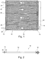
Figure 1 a side view of a condenser according to a first embodiment of the invention; -
Figure 2 a plan view of the condenser ofFigure 1 ; -
Figure 3 a section along the plane III-III ofFigure 2 ; -
Figure 4 a section along the plane IV ofFigure 3 ; -
Figure 5 a section along the plane V ofFigure 3 ; -
Figure 6 a section along the plane VI ofFigure 3 ; -
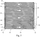
Figure 7 the condenser ofFigure 1 in a sectional view; -
Figure 8 a condenser according to a second embodiment in a view corresponding to that ofFigure 7 ; -
Figure 9 a condenser according to a third embodiment in a view corresponding to that ofFigure 7 ; -
Figure 10 a perspective view of a blank from which an insert for a condenser according to the invention can be manufactured; -
Figure 11 a perspective view of the blank ofFigure 10 according to a first processing step; -
Figure 12 a perspective view of the fully formed insert; -
Figure 13 the insert ofFigure 12 mounted on a cover; -
Figure 14 the cover ofFigure 13 mounted on a collecting tube; -
Figure 15 a schematic sectional view of the collecting tube ofFigure 14 with the formed heater canals; -
Figure 16 a plan view of the assembly known fromFigure 13 ; -
Figure 17 a side view of the assembly ofFigure 16 ; and -
Figure 18 a detail of the insert. -
Figures 1 to 7 show acondenser 10 according to a first embodiment. It is part of a coolant circuit of a motor vehicle air conditioner. - The
condenser 10 has afirst collecting tube 12, asecond collecting tube 14 and a multiplicity ofheater canals 16 which extend between the first and thesecond collecting tube - A receiver-
drier 18 is mounted at thesecond collecting tube 14. - The
first collecting tube 12 here is provided with aninlet 22 through which thecondenser 10 is supplied with coolant in the gaseous state. - An
outlet 24 is likewise mounted here at thefirst collecting tube 12, through which the coolant is discharged in the liquid state (at least for the most part) . - In
Figure 1 , the flow paths of the coolant through thecondenser 10 are indicated by the arrows 1 to 4. It can be seen that the coolant does not enter into theheater canals 16 at the height of thecoolant inlet 22, but laterally offset in the upper region of the condenser. The reason for this is that aflow canal 26 is formed inside thefirst collecting tube 12, which flow canal defines the "height" at which the coolant is delivered into thecollecting tube 12. - The
flow canal 26 is formed in that aninsert 28 is arranged inside thecollecting tube 12, which insert defines theflow canal 26 together with acover 30. - The
insert 28 has a generally trough-shaped elongated form, wherein one end (the lower end inFigure 3 ) is arranged a short distance below thecoolant inlet 22. The upper end is located at approximately half the height of the condenser. - The
insert 28 is provided with an overflow opening 32 at the upper end, through which theflow canal 26 is open to the inside of thecollecting tube 12. - The area of the
overflow opening 32 is preferably in the order of magnitude of 75 mm2 to 80 mm2. - At its lower end, the
flow canal 26 is virtually closed with respect to the interior of the collectingtube 12. Only a smalloil separation opening 34 is present. This has an area in the order of magnitude of preferably 5 mm2 to 7.5 mm2. - The coolant to be condensed is supplied to the
condenser 10 via thecoolant inlet 22 in the (substantially) gaseous state. Oil entrained by the gas collects at the lower end of theflow canal 26 and is discharged downwards through theoil separation opening 34 owing to the prevailing pressure ratios. The gaseous coolant then flows further upwards along theflow canal 26, where it enters into thefirst collecting tube 12 through theoverflow opening 32, and more precisely in a region between twodeflectors - The gaseous coolant flows between the
deflectors second collecting tube 14, it flows downwards into a region which is delimited between thedeflector 42 and afurther deflector 44. It flows here in the opposite direction back through theheater canals 16 in the direction of thearrow 2. - In the
first collecting tube 12, the coolant flows further downwards in a region delimited between thedeflector 42 and the bottom of the collectingtube 12 to then flow back to thesecond collecting tube 14 in the direction of thearrow 3. - It enters into the receiver-drier 18 here and flows upwards to flow in a region delimited above the
deflector 40 in the direction of thearrow 4 to thefirst collecting tube 12 and therefore to thecoolant outlet 24. - The temperature of the coolant decreases from the section 1 via the
section 2 to thesection 3, wherein the proportion of the liquid phase increases accordingly. The coolant is (at least virtually) completely in its liquid state in theregion 3. The coolant is supercooled in theregion 4. - The oil contained in the gaseous coolant, which is delivered downwards through the
oil separation opening 34 directly into the third section, is entrained accordingly by the liquid coolant and introduced back into the coolant circuit via thecoolant outlet 24. -
Figure 8 shows a second embodiment in which, likewise owing to theflow canal 26 formed with theinsert 28, the actual entry of the gaseous coolant into thefirst collecting tube 12 is "shifted". By means of thedeflectors condenser 10 to thesecond collecting tube 14, then in the middle to the first collecting tube and back to the second collecting tube again and then finally in the super cooler along thearrow 4 to thecoolant outlet 24. - In this embodiment too, the oil separation opening in the
insert 28 ensures that the oil arrives directly in "section 3" of the flow path of the coolant, i.e. at the point where the coolant is present in the liquid state (at least for the most part). -
Figure 9 shows a third embodiment in which thecoolant inlet 22 and thecoolant outlet 24 are arranged in the same manner as in the second embodiment. - However, only a
single deflector 40 is used, so that coolant flows from thefirst collecting tube 12 to thesecond collecting tube 14, and from there through the super cooler in the direction of thearrow 4 to thecoolant outlet 24. - The essential advantage of the
flow canal 26 formed by theinsert 28 consists in that, without external attachments and without altering the installation space required for thecondenser 10, the gaseous coolant can be introduced at the desired "height" into the collecting tube which is provided with thecoolant inlet 22. In other words, thecoolant inlet 22 can be arranged laterally offset relative to the level at which the coolant enters into the collectingtube 12. - The manufacture of the
insert 28 and the corresponding collecting tube is now described with reference toFigures 10 to 15 . - The starting point is the blank R shown in
Figure 10 , which is a rectangular sheet blank. The wall thickness of the sheet can be in the order of magnitude of 0.5 mm. In particular, the material used can essentially be the same as that which is also used for the collecting tube and the other components of thecondenser 10. - The openings, which later form the
overflow opening 32 and the oil separation opening 34 (seeFigure 11 ), can then be punched at the two mutually remote narrow ends of the blank R. - The blank R is then formed to produce the
insert 28 shown inFigure 12 . It has a trough-shaped form, wherein the end faces of the trough extend at an incline. Theoverflow opening 32 and theoil separation opening 34 are then arranged in these inclined end faces. The lateral edges of the insert are furthermore angled. - The
insert 28 is then mounted on acover 30. Thecover 30 is designed to be elongated and to have a curved cross section (see in particularFigure 5 ) and theinsert 28 is mounted on thecover 30 such that the two concave sides of thecomponents flow canal 26 is thus delimited between the twocomponents - The
insert 28 and thecover 30 can be clinched to one another. - As can also be seen in
Figure 13 , thecover 30 is provided with twoports 31, which later form thecoolant inlet 22 and thecoolant outlet 24. - As a next step, the
cover 30 is mounted on the collecting tube 12 (seeFigure 14 ). The collecting tube is provided with a multiplicity ofopenings 50 on its side remote from thecover 30, which lead into theheater canals 16. This can also be seen schematically inFigure 15 . - The cover and the collecting
tube 12 are preferably soldered to one another. - In
Figures 16 and 17 , thecover 30 with theinsert 28 mounted thereon can be seen in detail. Since the end walls of the trough-shapedinsert 28 which are provided with theopenings tube 12. - The oval form of the
overflow opening 32 is clearly shown inFigure 18 .
Claims (10)
- Condenser (10) having a first and a second collecting tube (12, 14), a plurality of heater canals (16), which extend between the two collecting tubes, an inlet (22) for a substantially gaseous coolant, which is arranged at one of the two collecting tubes (12, 14), and an outlet (24) for a substantially liquid coolant, which is arranged at one of the two collecting tubes (12, 14), wherein one of the collecting tubes (12, 14) is provided with an insert (28) which defines a flow canal (26) which is in communication at one end with the coolant inlet (22) and at the other end, by means of an overflow opening (32), with the inside of the collecting tube (12), characterized in that the insert (28) is in the form of a trough with inclined end faces.
- Condenser according to Claim 1, characterized in that the insert (28) is provided with an oil separation opening (34).
- Condenser according to Claim 2, characterized in that the oil separation opening (34) has an area in the order of magnitude of 0.75 to 9 mm2, in particular in the order of magnitude of 5 to 7.5 mm2.
- Condenser according to Claims 2 and 3 and according to Claim 1, characterized in that the oil separation opening (34) is arranged in one of the end faces of the insert (28).
- Condenser according to one of the preceding claims, characterized in that the overflow opening (32) has an area in the order of magnitude of 50 to 100 mm2, in particular in the order of magnitude of 75 to 80 mm2.
- Condenser according to one of the preceding claims, characterized in that the overflow opening (32) has an oval form.
- Condenser according to one of Claims 5 and 6 and according to Claim 1, characterized in that the overflow opening (32) is arranged in one of the end faces of the insert (28).
- Condenser according to one of the preceding claims, characterized in that the insert (28) is a bent part made from chased sheet.
- Condenser according to one of the preceding claims, characterized in that the insert (28) is fixedly connected to a cover (30).
- Condenser according to Claim 9, characterized in that the cover (30) is tightly connected to the collecting tube (12, 14).
Applications Claiming Priority (2)
| Application Number | Priority Date | Filing Date | Title |
|---|---|---|---|
| DE102016122310.7A DE102016122310A1 (en) | 2016-11-21 | 2016-11-21 | Condenser for an air conditioning system, in particular for a motor vehicle |
| PCT/EP2017/079805 WO2018091710A1 (en) | 2016-11-21 | 2017-11-20 | Condenser for an air conditioner, in particular for a motor vehicle |
Publications (2)
| Publication Number | Publication Date |
|---|---|
| EP3541645A1 EP3541645A1 (en) | 2019-09-25 |
| EP3541645B1 true EP3541645B1 (en) | 2021-08-18 |
Family
ID=60413203
Family Applications (1)
| Application Number | Title | Priority Date | Filing Date |
|---|---|---|---|
| EP17801450.2A Active EP3541645B1 (en) | 2016-11-21 | 2017-11-20 | Condenser for an air conditioner, in particular for a motor vehicle |
Country Status (4)
| Country | Link |
|---|---|
| EP (1) | EP3541645B1 (en) |
| CN (1) | CN110177702B (en) |
| DE (1) | DE102016122310A1 (en) |
| WO (1) | WO2018091710A1 (en) |
Families Citing this family (2)
| Publication number | Priority date | Publication date | Assignee | Title |
|---|---|---|---|---|
| EP3620727A1 (en) | 2018-09-06 | 2020-03-11 | Valeo Klimasysteme GmbH | Condenser with insert for an air conditioning system, in particular for a motor vehicle |
| LU102301B1 (en) * | 2020-12-14 | 2022-06-14 | Estra Automotive Systems Luxembourg S A R L | Heat exchanger for a vehicle |
Family Cites Families (11)
| Publication number | Priority date | Publication date | Assignee | Title |
|---|---|---|---|---|
| US5186246A (en) * | 1992-06-01 | 1993-02-16 | General Motors Corporation | Extruded coolant/refrigerant tank with separate headers |
| JP3159805B2 (en) * | 1992-10-12 | 2001-04-23 | 昭和アルミニウム株式会社 | Heat exchanger |
| JPH09189498A (en) * | 1996-01-09 | 1997-07-22 | Nippon Light Metal Co Ltd | Header with heat medium diversion promotion mechanism and method of molding the same |
| JP2000274880A (en) * | 1999-03-23 | 2000-10-06 | Bosch Automotive Systems Corp | Condenser |
| DE10155001A1 (en) * | 2001-11-08 | 2003-05-22 | Behr Gmbh & Co | Refrigerant condenser |
| DE10339072A1 (en) * | 2003-08-26 | 2005-03-24 | Daimlerchrysler Ag | Heat exchanger with integrated inlet and outlet |
| US7886811B2 (en) * | 2003-11-14 | 2011-02-15 | Showa Denko K.K. | Evaporator and process for fabricating same |
| US20080023185A1 (en) * | 2006-07-25 | 2008-01-31 | Henry Earl Beamer | Heat exchanger assembly |
| DE102010040025A1 (en) * | 2010-08-31 | 2012-03-01 | Behr Gmbh & Co. Kg | Refrigerant condenser assembly |
| CN102287969A (en) * | 2011-06-16 | 2011-12-21 | 广东美的电器股份有限公司 | Parallel flow heat exchanger |
| KR101317377B1 (en) * | 2011-11-21 | 2013-10-22 | 현대자동차주식회사 | Condenser for vehicle |
-
2016
- 2016-11-21 DE DE102016122310.7A patent/DE102016122310A1/en active Pending
-
2017
- 2017-11-20 WO PCT/EP2017/079805 patent/WO2018091710A1/en not_active Ceased
- 2017-11-20 EP EP17801450.2A patent/EP3541645B1/en active Active
- 2017-11-20 CN CN201780083498.4A patent/CN110177702B/en active Active
Also Published As
| Publication number | Publication date |
|---|---|
| WO2018091710A1 (en) | 2018-05-24 |
| DE102016122310A1 (en) | 2018-05-24 |
| CN110177702A (en) | 2019-08-27 |
| CN110177702B (en) | 2023-01-10 |
| EP3541645A1 (en) | 2019-09-25 |
Similar Documents
| Publication | Publication Date | Title |
|---|---|---|
| CN108779968B (en) | heat exchanger | |
| US5537839A (en) | Condenser with refrigerant drier | |
| EP3631336B1 (en) | Heat exchanger | |
| US10352598B2 (en) | Heat exchanger, in particular a condenser | |
| US20140224455A1 (en) | Condenser with a stack of heat exchanger plates | |
| US10094601B2 (en) | Condenser | |
| EP3541645B1 (en) | Condenser for an air conditioner, in particular for a motor vehicle | |
| EP2927631A1 (en) | Heat exchanger, especially a condenser | |
| JP2006214714A (en) | Condenser for air conditioner, especially condenser for air conditioner of automobile | |
| CN105102908B (en) | Collector | |
| US11662160B2 (en) | Collector tube for a heat exchanger | |
| US11365937B2 (en) | Collector tube for a heat exchanger | |
| EP0689016A1 (en) | Accumulator for an air conditioning system | |
| US8333085B2 (en) | Condensation water overflow protector for an evaporator | |
| US11143464B2 (en) | Collector tube for a heat exchanger | |
| US10215511B2 (en) | Receiver for a heat exchanger and heat exchanger, especially condenser, equipped thereof | |
| CN108072208B (en) | Condenser | |
| US20080156012A1 (en) | Condenser For An Air-Conditioning System, Particularly For A Motor Vehicle | |
| WO2020048870A1 (en) | Condenser with insert for an air conditioner, in particular for a motor vehicle | |
| EP3396292B1 (en) | Gas cooler | |
| JP2019138507A (en) | Evaporator with cold storage function | |
| EP4628818A1 (en) | Shell and tube condenser | |
| JP2007504423A (en) | Automotive heat exchanger unit | |
| EP3086074A1 (en) | Tubular element and heat exchanger | |
| CN119452219A (en) | Dual heat exchangers |
Legal Events
| Date | Code | Title | Description |
|---|---|---|---|
| STAA | Information on the status of an ep patent application or granted ep patent |
Free format text: STATUS: UNKNOWN |
|
| STAA | Information on the status of an ep patent application or granted ep patent |
Free format text: STATUS: THE INTERNATIONAL PUBLICATION HAS BEEN MADE |
|
| PUAI | Public reference made under article 153(3) epc to a published international application that has entered the european phase |
Free format text: ORIGINAL CODE: 0009012 |
|
| STAA | Information on the status of an ep patent application or granted ep patent |
Free format text: STATUS: REQUEST FOR EXAMINATION WAS MADE |
|
| 17P | Request for examination filed |
Effective date: 20190614 |
|
| AK | Designated contracting states |
Kind code of ref document: A1 Designated state(s): AL AT BE BG CH CY CZ DE DK EE ES FI FR GB GR HR HU IE IS IT LI LT LU LV MC MK MT NL NO PL PT RO RS SE SI SK SM TR |
|
| AX | Request for extension of the european patent |
Extension state: BA ME |
|
| DAV | Request for validation of the european patent (deleted) | ||
| DAX | Request for extension of the european patent (deleted) | ||
| STAA | Information on the status of an ep patent application or granted ep patent |
Free format text: STATUS: THE APPLICATION IS DEEMED TO BE WITHDRAWN |
|
| STAA | Information on the status of an ep patent application or granted ep patent |
Free format text: STATUS: REQUEST FOR EXAMINATION WAS MADE |
|
| 18D | Application deemed to be withdrawn |
Effective date: 20200603 |
|
| D18D | Application deemed to be withdrawn (deleted) | ||
| GRAP | Despatch of communication of intention to grant a patent |
Free format text: ORIGINAL CODE: EPIDOSNIGR1 |
|
| STAA | Information on the status of an ep patent application or granted ep patent |
Free format text: STATUS: GRANT OF PATENT IS INTENDED |
|
| INTG | Intention to grant announced |
Effective date: 20210310 |
|
| RIN1 | Information on inventor provided before grant (corrected) |
Inventor name: SEKTI, CONDRO Inventor name: GENGER, MICHAEL |
|
| GRAS | Grant fee paid |
Free format text: ORIGINAL CODE: EPIDOSNIGR3 |
|
| GRAA | (expected) grant |
Free format text: ORIGINAL CODE: 0009210 |
|
| STAA | Information on the status of an ep patent application or granted ep patent |
Free format text: STATUS: THE PATENT HAS BEEN GRANTED |
|
| AK | Designated contracting states |
Kind code of ref document: B1 Designated state(s): AL AT BE BG CH CY CZ DE DK EE ES FI FR GB GR HR HU IE IS IT LI LT LU LV MC MK MT NL NO PL PT RO RS SE SI SK SM TR |
|
| REG | Reference to a national code |
Ref country code: CH Ref legal event code: EP |
|
| REG | Reference to a national code |
Ref country code: DE Ref legal event code: R096 Ref document number: 602017044379 Country of ref document: DE |
|
| REG | Reference to a national code |
Ref country code: IE Ref legal event code: FG4D Ref country code: AT Ref legal event code: REF Ref document number: 1421325 Country of ref document: AT Kind code of ref document: T Effective date: 20210915 |
|
| REG | Reference to a national code |
Ref country code: LT Ref legal event code: MG9D |
|
| REG | Reference to a national code |
Ref country code: NL Ref legal event code: MP Effective date: 20210818 |
|
| REG | Reference to a national code |
Ref country code: AT Ref legal event code: MK05 Ref document number: 1421325 Country of ref document: AT Kind code of ref document: T Effective date: 20210818 |
|
| PG25 | Lapsed in a contracting state [announced via postgrant information from national office to epo] |
Ref country code: AT Free format text: LAPSE BECAUSE OF FAILURE TO SUBMIT A TRANSLATION OF THE DESCRIPTION OR TO PAY THE FEE WITHIN THE PRESCRIBED TIME-LIMIT Effective date: 20210818 Ref country code: BG Free format text: LAPSE BECAUSE OF FAILURE TO SUBMIT A TRANSLATION OF THE DESCRIPTION OR TO PAY THE FEE WITHIN THE PRESCRIBED TIME-LIMIT Effective date: 20211118 Ref country code: LT Free format text: LAPSE BECAUSE OF FAILURE TO SUBMIT A TRANSLATION OF THE DESCRIPTION OR TO PAY THE FEE WITHIN THE PRESCRIBED TIME-LIMIT Effective date: 20210818 Ref country code: NO Free format text: LAPSE BECAUSE OF FAILURE TO SUBMIT A TRANSLATION OF THE DESCRIPTION OR TO PAY THE FEE WITHIN THE PRESCRIBED TIME-LIMIT Effective date: 20211118 Ref country code: PT Free format text: LAPSE BECAUSE OF FAILURE TO SUBMIT A TRANSLATION OF THE DESCRIPTION OR TO PAY THE FEE WITHIN THE PRESCRIBED TIME-LIMIT Effective date: 20211220 Ref country code: RS Free format text: LAPSE BECAUSE OF FAILURE TO SUBMIT A TRANSLATION OF THE DESCRIPTION OR TO PAY THE FEE WITHIN THE PRESCRIBED TIME-LIMIT Effective date: 20210818 Ref country code: SE Free format text: LAPSE BECAUSE OF FAILURE TO SUBMIT A TRANSLATION OF THE DESCRIPTION OR TO PAY THE FEE WITHIN THE PRESCRIBED TIME-LIMIT Effective date: 20210818 Ref country code: HR Free format text: LAPSE BECAUSE OF FAILURE TO SUBMIT A TRANSLATION OF THE DESCRIPTION OR TO PAY THE FEE WITHIN THE PRESCRIBED TIME-LIMIT Effective date: 20210818 Ref country code: ES Free format text: LAPSE BECAUSE OF FAILURE TO SUBMIT A TRANSLATION OF THE DESCRIPTION OR TO PAY THE FEE WITHIN THE PRESCRIBED TIME-LIMIT Effective date: 20210818 Ref country code: FI Free format text: LAPSE BECAUSE OF FAILURE TO SUBMIT A TRANSLATION OF THE DESCRIPTION OR TO PAY THE FEE WITHIN THE PRESCRIBED TIME-LIMIT Effective date: 20210818 |
|
| PG25 | Lapsed in a contracting state [announced via postgrant information from national office to epo] |
Ref country code: PL Free format text: LAPSE BECAUSE OF FAILURE TO SUBMIT A TRANSLATION OF THE DESCRIPTION OR TO PAY THE FEE WITHIN THE PRESCRIBED TIME-LIMIT Effective date: 20210818 Ref country code: LV Free format text: LAPSE BECAUSE OF FAILURE TO SUBMIT A TRANSLATION OF THE DESCRIPTION OR TO PAY THE FEE WITHIN THE PRESCRIBED TIME-LIMIT Effective date: 20210818 Ref country code: GR Free format text: LAPSE BECAUSE OF FAILURE TO SUBMIT A TRANSLATION OF THE DESCRIPTION OR TO PAY THE FEE WITHIN THE PRESCRIBED TIME-LIMIT Effective date: 20211119 |
|
| PG25 | Lapsed in a contracting state [announced via postgrant information from national office to epo] |
Ref country code: NL Free format text: LAPSE BECAUSE OF FAILURE TO SUBMIT A TRANSLATION OF THE DESCRIPTION OR TO PAY THE FEE WITHIN THE PRESCRIBED TIME-LIMIT Effective date: 20210818 |
|
| PG25 | Lapsed in a contracting state [announced via postgrant information from national office to epo] |
Ref country code: DK Free format text: LAPSE BECAUSE OF FAILURE TO SUBMIT A TRANSLATION OF THE DESCRIPTION OR TO PAY THE FEE WITHIN THE PRESCRIBED TIME-LIMIT Effective date: 20210818 |
|
| REG | Reference to a national code |
Ref country code: DE Ref legal event code: R097 Ref document number: 602017044379 Country of ref document: DE |
|
| PG25 | Lapsed in a contracting state [announced via postgrant information from national office to epo] |
Ref country code: SM Free format text: LAPSE BECAUSE OF FAILURE TO SUBMIT A TRANSLATION OF THE DESCRIPTION OR TO PAY THE FEE WITHIN THE PRESCRIBED TIME-LIMIT Effective date: 20210818 Ref country code: SK Free format text: LAPSE BECAUSE OF FAILURE TO SUBMIT A TRANSLATION OF THE DESCRIPTION OR TO PAY THE FEE WITHIN THE PRESCRIBED TIME-LIMIT Effective date: 20210818 Ref country code: RO Free format text: LAPSE BECAUSE OF FAILURE TO SUBMIT A TRANSLATION OF THE DESCRIPTION OR TO PAY THE FEE WITHIN THE PRESCRIBED TIME-LIMIT Effective date: 20210818 Ref country code: EE Free format text: LAPSE BECAUSE OF FAILURE TO SUBMIT A TRANSLATION OF THE DESCRIPTION OR TO PAY THE FEE WITHIN THE PRESCRIBED TIME-LIMIT Effective date: 20210818 Ref country code: CZ Free format text: LAPSE BECAUSE OF FAILURE TO SUBMIT A TRANSLATION OF THE DESCRIPTION OR TO PAY THE FEE WITHIN THE PRESCRIBED TIME-LIMIT Effective date: 20210818 Ref country code: AL Free format text: LAPSE BECAUSE OF FAILURE TO SUBMIT A TRANSLATION OF THE DESCRIPTION OR TO PAY THE FEE WITHIN THE PRESCRIBED TIME-LIMIT Effective date: 20210818 |
|
| REG | Reference to a national code |
Ref country code: DE Ref legal event code: R119 Ref document number: 602017044379 Country of ref document: DE |
|
| PLBE | No opposition filed within time limit |
Free format text: ORIGINAL CODE: 0009261 |
|
| STAA | Information on the status of an ep patent application or granted ep patent |
Free format text: STATUS: NO OPPOSITION FILED WITHIN TIME LIMIT |
|
| PG25 | Lapsed in a contracting state [announced via postgrant information from national office to epo] |
Ref country code: MC Free format text: LAPSE BECAUSE OF FAILURE TO SUBMIT A TRANSLATION OF THE DESCRIPTION OR TO PAY THE FEE WITHIN THE PRESCRIBED TIME-LIMIT Effective date: 20210818 |
|
| REG | Reference to a national code |
Ref country code: CH Ref legal event code: PL |
|
| 26N | No opposition filed |
Effective date: 20220519 |
|
| PG25 | Lapsed in a contracting state [announced via postgrant information from national office to epo] |
Ref country code: LU Free format text: LAPSE BECAUSE OF NON-PAYMENT OF DUE FEES Effective date: 20211120 Ref country code: IT Free format text: LAPSE BECAUSE OF FAILURE TO SUBMIT A TRANSLATION OF THE DESCRIPTION OR TO PAY THE FEE WITHIN THE PRESCRIBED TIME-LIMIT Effective date: 20210818 Ref country code: BE Free format text: LAPSE BECAUSE OF NON-PAYMENT OF DUE FEES Effective date: 20211130 |
|
| REG | Reference to a national code |
Ref country code: BE Ref legal event code: MM Effective date: 20211130 |
|
| PG25 | Lapsed in a contracting state [announced via postgrant information from national office to epo] |
Ref country code: SI Free format text: LAPSE BECAUSE OF FAILURE TO SUBMIT A TRANSLATION OF THE DESCRIPTION OR TO PAY THE FEE WITHIN THE PRESCRIBED TIME-LIMIT Effective date: 20210818 |
|
| PG25 | Lapsed in a contracting state [announced via postgrant information from national office to epo] |
Ref country code: IE Free format text: LAPSE BECAUSE OF NON-PAYMENT OF DUE FEES Effective date: 20211120 Ref country code: DE Free format text: LAPSE BECAUSE OF NON-PAYMENT OF DUE FEES Effective date: 20220601 |
|
| PG25 | Lapsed in a contracting state [announced via postgrant information from national office to epo] |
Ref country code: FR Free format text: LAPSE BECAUSE OF NON-PAYMENT OF DUE FEES Effective date: 20211130 |
|
| PG25 | Lapsed in a contracting state [announced via postgrant information from national office to epo] |
Ref country code: CY Free format text: LAPSE BECAUSE OF FAILURE TO SUBMIT A TRANSLATION OF THE DESCRIPTION OR TO PAY THE FEE WITHIN THE PRESCRIBED TIME-LIMIT Effective date: 20210818 |
|
| PG25 | Lapsed in a contracting state [announced via postgrant information from national office to epo] |
Ref country code: LI Free format text: LAPSE BECAUSE OF NON-PAYMENT OF DUE FEES Effective date: 20220701 Ref country code: HU Free format text: LAPSE BECAUSE OF FAILURE TO SUBMIT A TRANSLATION OF THE DESCRIPTION OR TO PAY THE FEE WITHIN THE PRESCRIBED TIME-LIMIT; INVALID AB INITIO Effective date: 20171120 Ref country code: CH Free format text: LAPSE BECAUSE OF NON-PAYMENT OF DUE FEES Effective date: 20220701 |
|
| P01 | Opt-out of the competence of the unified patent court (upc) registered |
Effective date: 20230629 |
|
| PG25 | Lapsed in a contracting state [announced via postgrant information from national office to epo] |
Ref country code: MK Free format text: LAPSE BECAUSE OF FAILURE TO SUBMIT A TRANSLATION OF THE DESCRIPTION OR TO PAY THE FEE WITHIN THE PRESCRIBED TIME-LIMIT Effective date: 20210818 |
|
| PG25 | Lapsed in a contracting state [announced via postgrant information from national office to epo] |
Ref country code: MT Free format text: LAPSE BECAUSE OF FAILURE TO SUBMIT A TRANSLATION OF THE DESCRIPTION OR TO PAY THE FEE WITHIN THE PRESCRIBED TIME-LIMIT Effective date: 20210818 |
|
| PG25 | Lapsed in a contracting state [announced via postgrant information from national office to epo] |
Ref country code: TR Free format text: LAPSE BECAUSE OF FAILURE TO SUBMIT A TRANSLATION OF THE DESCRIPTION OR TO PAY THE FEE WITHIN THE PRESCRIBED TIME-LIMIT Effective date: 20210818 |
|
| PG25 | Lapsed in a contracting state [announced via postgrant information from national office to epo] |
Ref country code: GB Free format text: LAPSE BECAUSE OF FAILURE TO SUBMIT A TRANSLATION OF THE DESCRIPTION OR TO PAY THE FEE WITHIN THE PRESCRIBED TIME-LIMIT; INVALID AB INITIO Effective date: 20171120 |