EP3540887A1 - Marker für stromleitungskabeln oder dergleichen und verfahren zur installation des markers - Google Patents
Marker für stromleitungskabeln oder dergleichen und verfahren zur installation des markers Download PDFInfo
- Publication number
- EP3540887A1 EP3540887A1 EP16921266.9A EP16921266A EP3540887A1 EP 3540887 A1 EP3540887 A1 EP 3540887A1 EP 16921266 A EP16921266 A EP 16921266A EP 3540887 A1 EP3540887 A1 EP 3540887A1
- Authority
- EP
- European Patent Office
- Prior art keywords
- cable
- marker
- same
- central body
- area
- Prior art date
- Legal status (The legal status is an assumption and is not a legal conclusion. Google has not performed a legal analysis and makes no representation as to the accuracy of the status listed.)
- Withdrawn
Links
- 239000003550 marker Substances 0.000 title claims abstract description 38
- 238000000034 method Methods 0.000 title claims description 8
- 238000009434 installation Methods 0.000 claims abstract description 8
- 238000004804 winding Methods 0.000 claims abstract description 6
- 230000005489 elastic deformation Effects 0.000 claims abstract description 5
- 239000000463 material Substances 0.000 claims description 6
- 238000010276 construction Methods 0.000 description 4
- 239000004020 conductor Substances 0.000 description 3
- 230000000007 visual effect Effects 0.000 description 3
- 208000027418 Wounds and injury Diseases 0.000 description 2
- 206010014405 Electrocution Diseases 0.000 description 1
- 241000282412 Homo Species 0.000 description 1
- 241000282414 Homo sapiens Species 0.000 description 1
- 230000000295 complement effect Effects 0.000 description 1
- 230000007423 decrease Effects 0.000 description 1
- 230000000694 effects Effects 0.000 description 1
- 238000011900 installation process Methods 0.000 description 1
- 230000001617 migratory effect Effects 0.000 description 1
- 230000000422 nocturnal effect Effects 0.000 description 1
- 230000000717 retained effect Effects 0.000 description 1
- 239000000725 suspension Substances 0.000 description 1
Images


Classifications
-
- H—ELECTRICITY
- H02—GENERATION; CONVERSION OR DISTRIBUTION OF ELECTRIC POWER
- H02G—INSTALLATION OF ELECTRIC CABLES OR LINES, OR OF COMBINED OPTICAL AND ELECTRIC CABLES OR LINES
- H02G7/00—Overhead installations of electric lines or cables
-
- A—HUMAN NECESSITIES
- A01—AGRICULTURE; FORESTRY; ANIMAL HUSBANDRY; HUNTING; TRAPPING; FISHING
- A01M—CATCHING, TRAPPING OR SCARING OF ANIMALS; APPARATUS FOR THE DESTRUCTION OF NOXIOUS ANIMALS OR NOXIOUS PLANTS
- A01M29/00—Scaring or repelling devices, e.g. bird-scaring apparatus
- A01M29/06—Scaring or repelling devices, e.g. bird-scaring apparatus using visual means, e.g. scarecrows, moving elements, specific shapes, patterns or the like
- A01M29/08—Scaring or repelling devices, e.g. bird-scaring apparatus using visual means, e.g. scarecrows, moving elements, specific shapes, patterns or the like using reflection, colours or films with specific transparency or reflectivity
-
- G—PHYSICS
- G09—EDUCATION; CRYPTOGRAPHY; DISPLAY; ADVERTISING; SEALS
- G09F—DISPLAYING; ADVERTISING; SIGNS; LABELS OR NAME-PLATES; SEALS
- G09F3/00—Labels, tag tickets, or similar identification or indication means; Seals; Postage or like stamps
- G09F3/08—Fastening or securing by means not forming part of the material of the label itself
- G09F3/18—Casings, frames or enclosures for labels
- G09F3/20—Casings, frames or enclosures for labels for adjustable, removable, or interchangeable labels
- G09F3/205—Casings, frames or enclosures for labels for adjustable, removable, or interchangeable labels specially adapted for electric cables, pipes or the like
-
- H—ELECTRICITY
- H01—ELECTRIC ELEMENTS
- H01B—CABLES; CONDUCTORS; INSULATORS; SELECTION OF MATERIALS FOR THEIR CONDUCTIVE, INSULATING OR DIELECTRIC PROPERTIES
- H01B13/00—Apparatus or processes specially adapted for manufacturing conductors or cables
- H01B13/34—Apparatus or processes specially adapted for manufacturing conductors or cables for marking conductors or cables
-
- H—ELECTRICITY
- H01—ELECTRIC ELEMENTS
- H01B—CABLES; CONDUCTORS; INSULATORS; SELECTION OF MATERIALS FOR THEIR CONDUCTIVE, INSULATING OR DIELECTRIC PROPERTIES
- H01B7/00—Insulated conductors or cables characterised by their form
- H01B7/36—Insulated conductors or cables characterised by their form with distinguishing or length marks
- H01B7/368—Insulated conductors or cables characterised by their form with distinguishing or length marks being a sleeve, ferrule, tag, clip, label or short length strip
-
- Y—GENERAL TAGGING OF NEW TECHNOLOGICAL DEVELOPMENTS; GENERAL TAGGING OF CROSS-SECTIONAL TECHNOLOGIES SPANNING OVER SEVERAL SECTIONS OF THE IPC; TECHNICAL SUBJECTS COVERED BY FORMER USPC CROSS-REFERENCE ART COLLECTIONS [XRACs] AND DIGESTS
- Y10—TECHNICAL SUBJECTS COVERED BY FORMER USPC
- Y10S—TECHNICAL SUBJECTS COVERED BY FORMER USPC CROSS-REFERENCE ART COLLECTIONS [XRACs] AND DIGESTS
- Y10S116/00—Signals and indicators
- Y10S116/33—Indicator for elevated cables
Definitions
- the present invention relates to a marker for overhead cables, power lines or telephone lines, primarily intended to mark them so that birds are warned of the existence of the cables.
- it can also serve as an aerial marker for airplanes, helicopters and other types of gliders that may be flying in the area, preventing the same from hitting the cables in any of the cases.
- the invention provides a marker for new overhead power lines; wherein the markers are placed fastened to the cable when the same is still on the ground, or near the ground, and as it emerges from the reel to be mounted suspended on the corresponding towers conveniently arranged on the ground.
- the overhead cables for electric power or telephone networks affect the fauna and especially the birds of the area in which they are installed, and to a greater degree migratory birds, given that they can be electrocuted if they touch two phases of a suspended electric cable or if they hit the cable during flight by not being aware of its presence.
- power lines have a specific power the risk of electrocution is reduced because the phases are significantly separated, and furthermore, the risk of birds crashing into them is lower because these conductors have a large diameter, making them visible on a clear day by birds that fly in the area; however, this visibility is easily reduced on a cloudy day.
- warning markers generally consist of a rod that has a central area wound in a circle and which extends perpendicularly to the centre according to two branches wound in a spiral that wind around the cable, so that this circle is orthogonal with respect to the same, thereby being more visible.
- documents US3183883 and EP1087487 describe markers with these characteristics for an electrical grid, intended for protecting birds, formed by a spiral marker that include a central coil integral with lateral coils that have a winding radius that decreases and which end, on each side, at a preformed spiral with a slightly smaller diameter than that of the electric conductor to which these coils are fastened by the winding and elastic deformation thereof.
- markers formed by a ball on the cable, immobilised by any means; in any of the cases the marker has an enclosure that goes around the cable, and therefore, these types of markers must be placed on the line once the line is already suspended and in a manual fashion, requiring the operator to either be moved in a cart suspended by the cable itself, or to be hanging from a helicopter and suspended in the air above or on one side of the cable; in either case at risk of an accident and having to cut the electric power on the line beforehand.
- markers as described in the aforementioned document ES2048651 , are placed with the help of a machine designed for this purpose; this machine moving autonomously on the cable while being remotely controlled; however, it is necessary to lift this machine onto the starting tower and, once there, place it into position on the cable so that it can begin to operate, placing the markers as it moves along said cable.
- the problem presented by all of the known marker systems currently lies in the fact that the placement of the markers must necessarily be done on a line that is already installed, given that all known markers have a body that encloses the cable and, therefore, cannot pass through a pulley that is placed on the closest support tower to guide and slide the cable to the next support tower. Since none of the existing markers can pass through this pulley, the only way to operate is to place them on the line that is already installed, as was previously explained, which is the method that has been used since bird flight diverters began to be used.
- the object of the present invention is a marker that solves the aforementioned problems, given that it is placed directly on the cable, immediately after it is unwound from the reel or drum supplying the same and before it leaves the ground, or the vehicle in which said reel is situated, and is sent to the upper area of the support tower of the line under construction, on which a pulley is placed which allows the cable to be guided to the next support tower, following the direction of the suspension.
- this marker has a configuration in such a way that it passes through the pulley or pulleys situated on the upper area of the supports without difficulty, and once mounted on the cable, it stays at the point at which it is fastened without possible longitudinal sliding in one or the other direction, even when passing through said pulleys or when hit by the effect of the wind or other atmospheric elements when the cable is in a definitive position and the line is active.
- markers are manually placed on the cable by an operator who is situated after the reel on which the cable is wound, in the area where the cable comes out for the line under construction, on a safety crane basket; thereby avoiding the risks of working high off the ground and facilitating the installation process, since it only takes a few seconds for a single operator to place a marker; in fact, the process of mounting the cable does not stop and the placement of the marker is done while it advances a few metres. Since the cable being unwound from the drum or reel supplying the same runs to the top of the nearest tower, describing a catenary curve, in the area of the installation of the markers, said cable hardly has an inclination and, thus, this is one of the areas in which the markers can be mounted more comfortably on the cable.
- the installation of the markers can also be done by an operator situated on the tower, either before or after the cable passes through the pulley of the first support from which the line under construction is being mounted.
- the mounting of the marker is done in an area of the cable close to the first support from which the line is being mounted.
- a marker of these characteristics comprises two essential parts: on the one hand the body of the marker, which has a longitudinal inner cavity, opening at the bottom and having dimensions that are suitable to allow it to be placed on the corresponding cable by pressing it down on the same, the marker thereby being retained in the mounting position, the definitive fastening subsequently being carried out by means of a preformed spiral.
- the body of the marker has several flexible lateral flaps, which make up the visual part of the same and which can be seen at a certain distance and from any direction.
- the marker itself has means for the immobilisation thereof on the cable, consisting of a preformed spiral with a slightly smaller diameter than that of said cable, which winds and/or couples to the central body of the marker in order to keep it firmly joined to the cable when fastening to the same by the winding and the elastic deformation of the coils thereof.
- the configuration of the lateral flaps, fastened to the central body of the marker can be any configuration that is suitable for the same to be seen by birds, or by airplanes or other gadgets flying in the area; they will preferably have an area to which a reflective and/or luminescent material is applied in order to facilitate the visibility thereof.
- the marker for overhead cables, electrical lines or similar is intended to indicate and/or warn birds of the existence of cables (3), and, furthermore, is intended to warn humans that fly in the area in an airplane, helicopter, glider, or any other type of flying gadget.
- the marker comprises two essential elements: a central body (1), which has flaps (12, 15) that constitute the visual element of the marker, and means for fastening this central body (1) to the cable (3), together forming an element that, once mounted on said cable (3), before the installation thereof on the corresponding overhead line, does not have any protruding element on the bottom face thereof, such that the cable (3) with the marker mounted on the same, can pass in an unimpeded fashion through the pulleys (8) used in the subsequent mounting of said cable (3).
- the central body (1) has a cylindrical configuration, with a longitudinal inner cavity (11) open at the bottom. This body is made of a flexible material, such that it is placed on the corresponding cable (3) by pressing this piece downwards on the same. This central body (1) is the means for supporting a series of flexible lateral flaps (12), which form the visually observable pattern that can be seen from a certain distance and from any direction.
- Figures 1 and 2 show markers that have flexible lateral flaps (12) that, with the central body (1), form a raised inverted V-shape configuration.
- the flexibility of the same and length thereof is slightly less than the radius of the pulley (8), in order to allow for the markers to pass through the same.
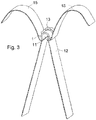
- Figure 3 shows a variant embodiment in which the central body (1) has a second set of flaps (15) in an essentially vertical arrangement, upwards, also with a flexible nature, which fall downwards by the very weight of the same towards the sides, thereby simulating a bird of prey and more easily scaring off other birds.
- the flaps (12) and/or (15), at least on the upper face thereof, have an area (14) with a reflective and/or photoluminescent material, so as to make them more visible both during the day and during the night, both for human beings and for nocturnal birds, which in twilight hours are at greater risk of crashing into the cable.
- the same is made up of a spiral (2), which is preformed with a diameter that is slightly smaller than that of the cable (3), which winds and/or couples to the central body (1) of the marker, keeping it firmly joined to the cable (3) by fastening to the same by the winding and elastic deformation of the coils thereof.
- the central body (1) has ring or hole (13) on the upper area thereof that has the function of fastening said preformed spiral (2) to the same.
- FIG 4 shows the installation of the cable (3), for example a high voltage power line, on which, as the cable (3) is being mounted, a series of bird flight diverters will be placed, such as the ones described throughout this specification.
- the cable (3) is supplied from a reel or drum (4), which a brake machine (5) unwinds as cable is pulled from the same; to do so, it is run through a pulley (8), placed high on a tower (6) and pulled to the next support in line.
- the operator (7) is situated at the point where the cable (3) comes out of the reel (4) and manually places the markers, one after the other, on the cable, approximately at a pre-calculated distance, without needing to stop the process of pulling and mounting the cable (3).
- the markers are firmly fastened to the cable and, given their configuration, when they reach the pulley (8) they pass through the same without a problem and as a result are positioned along the line once it is installed, constituting a visual pattern, for which they were created.
- the installation is done by an operator (9) situated on the tower (6), either before or after the cable (3) passes through the pulley (8) situated on the first support (6) from which the line under construction is being mounted.
Landscapes
- Life Sciences & Earth Sciences (AREA)
- Engineering & Computer Science (AREA)
- Birds (AREA)
- General Physics & Mathematics (AREA)
- Theoretical Computer Science (AREA)
- Physics & Mathematics (AREA)
- Manufacturing & Machinery (AREA)
- Insects & Arthropods (AREA)
- Pest Control & Pesticides (AREA)
- Wood Science & Technology (AREA)
- Zoology (AREA)
- Environmental Sciences (AREA)
- Catching Or Destruction (AREA)
- Suspension Of Electric Lines Or Cables (AREA)
Applications Claiming Priority (1)
| Application Number | Priority Date | Filing Date | Title |
|---|---|---|---|
| PCT/ES2016/070810 WO2018087404A1 (es) | 2016-11-14 | 2016-11-14 | Baliza para cables de lineas eléctricas o similares y método de instalación de estas balizas |
Publications (2)
| Publication Number | Publication Date |
|---|---|
| EP3540887A1 true EP3540887A1 (de) | 2019-09-18 |
| EP3540887A4 EP3540887A4 (de) | 2020-05-13 |
Family
ID=62109129
Family Applications (1)
| Application Number | Title | Priority Date | Filing Date |
|---|---|---|---|
| EP16921266.9A Withdrawn EP3540887A4 (de) | 2016-11-14 | 2016-11-14 | Marker für stromleitungskabeln oder dergleichen und verfahren zur installation des markers |
Country Status (2)
| Country | Link |
|---|---|
| EP (1) | EP3540887A4 (de) |
| WO (1) | WO2018087404A1 (de) |
Cited By (2)
| Publication number | Priority date | Publication date | Assignee | Title |
|---|---|---|---|---|
| RU2828832C1 (ru) * | 2023-10-10 | 2024-10-21 | Общество с ограниченной ответственностью "Лаборатория будущего" | Способ установки оборудования на провод и устройство для его осуществления |
| EP4418858A4 (de) * | 2021-10-18 | 2025-10-08 | Hubbell Inc | Flugumlenkanordnungen für luftleiter |
Families Citing this family (1)
| Publication number | Priority date | Publication date | Assignee | Title |
|---|---|---|---|---|
| ES2852004B2 (es) * | 2020-03-04 | 2022-06-20 | Apresa Plp Spain S A | Sistema y proceso de instalacion de accesorios helicoidales con dispositivos de senalizacion en cables de lineas electricas |
Family Cites Families (11)
| Publication number | Priority date | Publication date | Assignee | Title |
|---|---|---|---|---|
| US3183883A (en) | 1961-08-03 | 1965-05-18 | Preformed Line Products Co | Indicating device for cables |
| US3391244A (en) * | 1965-09-14 | 1968-07-02 | John A. Moll | Foreign material eliminator and aerial warning marker for overhead conductors |
| US4620059A (en) * | 1985-12-03 | 1986-10-28 | Preformed Line Products Company | Cable vibration dampener and method of installing |
| US4742796A (en) * | 1986-10-10 | 1988-05-10 | Halsey Larry L | Fence wire location marker |
| ES2048651B1 (es) | 1992-06-05 | 1996-09-01 | Preformados Metalicos Sa De | Baliza para cables de lineas electricas o similares y un dispositivo para su colocacion. |
| US5372335A (en) * | 1992-12-18 | 1994-12-13 | Scott H. Yenzer | Aerial marker ball and method of placement |
| FR2800523B1 (fr) | 1999-09-22 | 2001-12-07 | Dervaux | Spirale de balisage pour reseau electrique |
| UY29780A1 (es) * | 2005-09-05 | 2007-03-30 | Interconexion Electrica S A E | Dispositivo desviador de vuelo de aves y su sistema de sujecion a cables o alambres aereos |
| US8869732B1 (en) * | 2009-06-02 | 2014-10-28 | Ab Hammarprodukter | Bird diverter |
| US9706767B2 (en) * | 2011-04-08 | 2017-07-18 | Power Line Sentry, Llc | Collision aversion system |
| GB2526334A (en) * | 2014-05-21 | 2015-11-25 | Preformed Line Products Great Britain Ltd | Bird flight diverter |
-
2016
- 2016-11-14 WO PCT/ES2016/070810 patent/WO2018087404A1/es not_active Ceased
- 2016-11-14 EP EP16921266.9A patent/EP3540887A4/de not_active Withdrawn
Cited By (3)
| Publication number | Priority date | Publication date | Assignee | Title |
|---|---|---|---|---|
| EP4418858A4 (de) * | 2021-10-18 | 2025-10-08 | Hubbell Inc | Flugumlenkanordnungen für luftleiter |
| US12446571B2 (en) | 2021-10-18 | 2025-10-21 | Hubbell Incorporated | Flight diverter assemblies for aerial conductors |
| RU2828832C1 (ru) * | 2023-10-10 | 2024-10-21 | Общество с ограниченной ответственностью "Лаборатория будущего" | Способ установки оборудования на провод и устройство для его осуществления |
Also Published As
| Publication number | Publication date |
|---|---|
| WO2018087404A1 (es) | 2018-05-17 |
| EP3540887A4 (de) | 2020-05-13 |
Similar Documents
| Publication | Publication Date | Title |
|---|---|---|
| AU2013261044B2 (en) | Point take-off and landing of unmanned flying objects | |
| US8500360B1 (en) | Traffic barrier deployment system | |
| JP6406784B2 (ja) | パイロットロープの延線方法、最終ロープの撤去方法、および、これに用いる無人マルチコプタ | |
| KR101551827B1 (ko) | 모의 낙하훈련 장치 | |
| EP3271575B1 (de) | Traktionsluftvorrichtung, luftvorrichtung für eine windkraftanlage und windkraftanlage zur stromerzeugung, mit einer traktionsluftvorrichtung ausgestattetes schiff | |
| EP3540887A1 (de) | Marker für stromleitungskabeln oder dergleichen und verfahren zur installation des markers | |
| CN201134645Y (zh) | 高压线路导、地线异物处理装置 | |
| US2373086A (en) | Transportation method | |
| JP2015217901A (ja) | マルチコプター | |
| JP2814189B2 (ja) | 無人ヘリコプターによる延線工法及び装置 | |
| EP1602576B1 (de) | Verlangsamungssystem für ein unbemanntes Fluggerät | |
| EP1378041A1 (de) | Verfahren und einrichtung zum entfernen von eis und schnee von einer stromleitung | |
| CN105914658A (zh) | 一种基于弧垂控制的无人机微张力引绳牵放方法 | |
| CN110165602B (zh) | 一种高压架线用系统及方法 | |
| CN201528159U (zh) | 无人直升机电力展放引导绳的展放系统 | |
| EP0031855A1 (de) | Vogelwarnvorrichtungen und Montageverfahren | |
| CN115176792A (zh) | 一种防小动物攀爬配电设备的装置 | |
| AU2025202326A1 (en) | Power line stringing system and method | |
| CN207782288U (zh) | 应用于无人机的滑动机构 | |
| CN101964502A (zh) | 利用遥控固定翼飞机展放初导绳的方法 | |
| WO2024147141A1 (en) | Bird deflector aerial deployment device and method | |
| WO2018222056A1 (en) | Visual aid for preventing wire strike | |
| AU2022320129A1 (en) | Line attachment devices and methods for use thereof | |
| CN113665832A (zh) | 无人机智能化机场地面系统 | |
| EP2868917A1 (de) | Halteleine und Verfahren zur Herstellung von Windenergie aus Luft |
Legal Events
| Date | Code | Title | Description |
|---|---|---|---|
| PUAI | Public reference made under article 153(3) epc to a published international application that has entered the european phase |
Free format text: ORIGINAL CODE: 0009012 |
|
| 17P | Request for examination filed |
Effective date: 20190605 |
|
| AK | Designated contracting states |
Kind code of ref document: A1 Designated state(s): AL AT BE BG CH CY CZ DE DK EE ES FI FR GB GR HR HU IE IS IT LI LT LU LV MC MK MT NL NO PL PT RO RS SE SI SK SM TR |
|
| AX | Request for extension of the european patent |
Extension state: BA ME |
|
| DAV | Request for validation of the european patent (deleted) | ||
| DAX | Request for extension of the european patent (deleted) | ||
| STAA | Information on the status of an ep patent application or granted ep patent |
Free format text: STATUS: THE APPLICATION HAS BEEN WITHDRAWN |
|
| A4 | Supplementary search report drawn up and despatched |
Effective date: 20200415 |
|
| RIC1 | Information provided on ipc code assigned before grant |
Ipc: A01M 29/00 20110101ALI20200407BHEP Ipc: A01M 29/08 20110101ALI20200407BHEP Ipc: H02G 7/00 20060101AFI20200407BHEP |
|
| 18W | Application withdrawn |
Effective date: 20200423 |