EP3540751B1 - Electrical switch - Google Patents
Electrical switch Download PDFInfo
- Publication number
- EP3540751B1 EP3540751B1 EP18382180.0A EP18382180A EP3540751B1 EP 3540751 B1 EP3540751 B1 EP 3540751B1 EP 18382180 A EP18382180 A EP 18382180A EP 3540751 B1 EP3540751 B1 EP 3540751B1
- Authority
- EP
- European Patent Office
- Prior art keywords
- striker
- mechanism according
- electrical mechanism
- actuating means
- rocking lever
- Prior art date
- Legal status (The legal status is an assumption and is not a legal conclusion. Google has not performed a legal analysis and makes no representation as to the accuracy of the status listed.)
- Active
Links
Images


Classifications
-
- H—ELECTRICITY
- H01—ELECTRIC ELEMENTS
- H01H—ELECTRIC SWITCHES; RELAYS; SELECTORS; EMERGENCY PROTECTIVE DEVICES
- H01H13/00—Switches having rectilinearly-movable operating part or parts adapted for pushing or pulling in one direction only, e.g. push-button switch
- H01H13/02—Details
- H01H13/12—Movable parts; Contacts mounted thereon
- H01H13/20—Driving mechanisms
-
- H—ELECTRICITY
- H01—ELECTRIC ELEMENTS
- H01H—ELECTRIC SWITCHES; RELAYS; SELECTORS; EMERGENCY PROTECTIVE DEVICES
- H01H13/00—Switches having rectilinearly-movable operating part or parts adapted for pushing or pulling in one direction only, e.g. push-button switch
- H01H13/02—Details
- H01H13/12—Movable parts; Contacts mounted thereon
- H01H13/14—Operating parts, e.g. push-button
-
- H—ELECTRICITY
- H01—ELECTRIC ELEMENTS
- H01H—ELECTRIC SWITCHES; RELAYS; SELECTORS; EMERGENCY PROTECTIVE DEVICES
- H01H13/00—Switches having rectilinearly-movable operating part or parts adapted for pushing or pulling in one direction only, e.g. push-button switch
- H01H13/02—Details
- H01H13/26—Snap-action arrangements depending upon deformation of elastic members
- H01H13/28—Snap-action arrangements depending upon deformation of elastic members using compression or extension of coil springs
-
- H—ELECTRICITY
- H01—ELECTRIC ELEMENTS
- H01H—ELECTRIC SWITCHES; RELAYS; SELECTORS; EMERGENCY PROTECTIVE DEVICES
- H01H13/00—Switches having rectilinearly-movable operating part or parts adapted for pushing or pulling in one direction only, e.g. push-button switch
- H01H13/50—Switches having rectilinearly-movable operating part or parts adapted for pushing or pulling in one direction only, e.g. push-button switch having a single operating member
- H01H13/56—Switches having rectilinearly-movable operating part or parts adapted for pushing or pulling in one direction only, e.g. push-button switch having a single operating member the contact returning to its original state upon the next application of operating force
- H01H13/60—Switches having rectilinearly-movable operating part or parts adapted for pushing or pulling in one direction only, e.g. push-button switch having a single operating member the contact returning to its original state upon the next application of operating force with contact-driving member moved alternately in opposite directions
-
- H—ELECTRICITY
- H01—ELECTRIC ELEMENTS
- H01H—ELECTRIC SWITCHES; RELAYS; SELECTORS; EMERGENCY PROTECTIVE DEVICES
- H01H23/00—Tumbler or rocker switches, i.e. switches characterised by being operated by rocking an operating member in the form of a rocker button
- H01H23/02—Details
- H01H23/12—Movable parts; Contacts mounted thereon
- H01H23/16—Driving mechanisms
- H01H23/20—Driving mechanisms having snap action
- H01H23/205—Driving mechanisms having snap action using a compression spring between tumbler and an articulated contact plate
Definitions
- the present invention relates to an electrical mechanism, such as an electric switch or push button, especially of the type which is actuated by a pivoting spindle that enables the position of an electric contact associated thereto to change.
- pivoting spindle electrical mechanisms usually have the following main components: an actuating means, a striker and a rocking lever, arranged in an ordered manner on an axial axis.
- the actuating means is connected to a cover or button that the user interacts with in order to apply an actuation or pushing force on the mechanism, which is transmitted to the striker by said actuating means.
- the action of the force on the striker causes a downward movement thereof that enables it to engage with the rocking lever.
- the rocking lever makes a pivoting movement and changes its position.
- the position change of the rocking lever in turn causes the position change of an electrical contact attached thereto, which causes the connection or disconnection of an electrical circuit.
- a spring connected to the striker enables said striker to move to its resting position once the actuation force is released, disengaging it from the rocking lever.
- this problem originates from the very manufacture and/or assembly of the mechanism. Specifically, when the main components are assembled in an off-centered or misaligned manner with respect to the axial axis.
- the spring of the striker is usually one of the most critical elements in this sense, since the coils of the upper and lower ends thereof often do not end in complete loops, thus producing a lack of parallelism between said ends.
- a slight inclination of the spring is usually produced, in other words, a slight inclination with respect to the axial axis, which causes the striker to descend deviated with respect to said axis. Therefore, the assembly of said springs requires adequate selection of the spring type and high accuracy in the assembly thereof (a difficult aspect to ensure in mass production).
- the present invention solves the aforementioned problems thanks to a configuration of the pivoting spindle that achieves greater centering of the actuation force on the striker and/or greater parallelism of said force with respect to the axial axis.
- said configuration optimizes the design of the main components of the pivoting spindle, reducing the amount of material needed for the manufacture thereof, reducing their size and adjusting their arrangement inside the mechanism to take up the least amount of space possible.
- the two contact points are arranged on an actuation plane perpendicular to the axial axis.
- the two contact points are arranged symmetrically with respect to the axial axis.
- the two contact points establish a distance therebetween of 0.2 mm to 4 mm. Said distance directly affects the actuation force needed to cause the rocking lever to rotate, which in turn causes the position change thereof. Specifically, the greater the distance between the contact points, the greater the actuation force needed to cause the rocking lever to rotate and vice versa.
- the distance between the two contact points is from 0.4 to 1 mm, and more specifically, from 0.5 mm to 0.8 mm, in order to have a minimum effect on the pushing force and on the feel of the mechanism.
- the two contact points allow the actuation force to be centered on the striker and therefore have greater parallelism with respect to the axial axis, forcing the striker to move straight downward in the initial path until it engages with the rocking lever, in other words, achieving transmission of the vertical movement.
- the striker preferably comprises a flat receiving area configured to come in contact with the actuating means.
- the striker comprises an upper part that has a substantially rectangular shape. Firstly, this enables the width of the striker to be reduced, gaining space for the rotation thereof during its return aided by the spring after changing the position of the rocking lever. Secondly, said substantially rectangular shape enables the mass of the striker to be reduced, which in turn enables the force needed to cause the return of said striker to the resting position as well as the manufacturing costs to be reduced. Furthermore, this reduction of the return force enables springs with less elastic force, which usually offer greater parallelism, for example, a spring with 1.4 N, to be selected.
- the upper part comprises two flanges that extend laterally in opposite directions with respect to said upper part to receive an upper end of the spring.
- the reception of the upper end of the spring does not need the final coil of the spring to completely rest against the upper part, but only a partial reception of said coil by the two opposite sides thereof, which also entails material and cost savings with respect to the flanges or circular rims on which the outermost coils completely rest.
- the striker comprises a lower part from which two lower extensions extend symmetrically, each one being configured to engage with a position of the rocking lever.
- the striker comprises an intermediate prismatic or cylindrical part between the upper part and the lower part that is hollow on the inside, in order to further reduce the mass thereof.
- the actuating means preferably comprises a transmission area having two transmission points configured to come in contact with the striker.
- the transmission points can be made in several ways, for example, as vertices, peaks, edges and/or ends thereof, corners, protrusions, etc., based on the constructive configuration and/or geometry of the transmission area.
- the actuating means comprises a substantially semi-spherical or curved transmission part, partially divided by a central strip that extends over the surface of said transmission part.
- the actuating means is joined to a flexible section, where said flexible section is in turn joined to a cover defining a rotation axis of said actuating means.
- the flat receiving area is on the actuating means, while the two transmission points are on the striker.
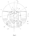
- Figure 1 shows the electrical mechanism (1) of the present invention in the resting position, before applying an actuation or pushing force (F) on a button (not shown) attached to the actuating means (4).
- the button and the actuating means (4) can be integrated into the same part, or form part of an actuation assembly as separated parts thereof along with other elements.
- the electrical mechanism (1) constitutes an electrical switch.
- said electrical mechanism (1) comprises an axial axis (1 Y ) in which the following components are arranged in an orderly manner:
- Figure 2 shows the electrical mechanism (1) of the present invention in the initial working position, once the actuation or pushing force (F) is applied and at the exact moment when the striker (3) engages with the rocking lever (5) in the first position (P 1 ).
- Figure 3 shows a detailed view in which the situation shown in Figure 2 is shown with greater clarity.
- the two contact points (C 1 , C 2 ) allow the actuation force (F) to be centered on the striker (3) and, therefore, have greater parallelism with respect to the axial axis (1 Y ), forcing the striker (3) to move straight downward in the initial path until it engages with the rocking lever (2).
- the two contact points (C 1 , C 2 ) are arranged on an actuation plane (P) perpendicular to the axial axis (1 Y ), symmetrically with respect to said axial axis (1 Y ) and establishing a distance (A) therebetween.
- the two contact points (C 1 , C 2 ) establish a distance (A) therebetween of 0.2 mm to 4 mm.
- the distance (A) between the contact points (C 1 , C 2 ) is from 0.4 mm to 1 mm, and more specifically, from 0.5 mm to 0.8 mm, in order to have a minimum effect on the pushing force (F) and on the feel of the mechanism (1).
- Figure 3 also shows in greater detail that the electrical mechanism (1) comprises a housing (6) arranged between the rocking lever (2) and the actuating means (4), configured to house the striker (3) and the spring (5), and which has a lower border (61) configured to receive a lower end (52) of the spring (5).
- the electrical mechanism (1) comprises a housing (6) arranged between the rocking lever (2) and the actuating means (4), configured to house the striker (3) and the spring (5), and which has a lower border (61) configured to receive a lower end (52) of the spring (5).
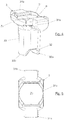
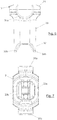
- FIG. 4-7 shows different views of the striker (3).
- the striker (3) comprises a flat receiving area (Z 3 ) configured to come in contact with the actuating means (4). Said receiving area (Z 3 ) determines the actuation plane (P).
- the striker (3) comprises an upper part (31) that has a substantially rectangular shape (31c).
- the upper part (31) comprises two flanges (31a, 31b) that extend laterally in opposite directions with respect to said upper part (31) to receive an upper end (51) of the spring (5) Figure 3 .
- the striker (3) comprises a lower part (32) from which two lower extensions (32a, 32b) extend symmetrically, each one being configured to engage with a position (P 1 , P 2 ) of the rocking lever (2).
- the striker (3) comprises an intermediate prismatic or cylindrical part (33) between the upper part (31) and the lower part (32) that is hollow on the inside.
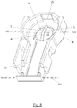
- FIG 8 shows a bottom perspective view of the actuating means (4).
- said actuating means (4) comprises a transmission area (Z 4 ) having two transmission points (T 1 , T 2 ) configured to come in contact with the striker (3).
- the actuating means (4) comprises a substantially semi-spherical or curved transmission part (41), partially divided by a central strip (42) that extends over the surface of said transmission part (41).
- Figure 9a shows the electrical mechanism (1) in the resting position shown in Figure 1 .
- the rocking lever (2) is in the first position (P 1 ) disengaged from the striker (3).
- Figure 9b shows the electrical mechanism (1) in the initial working position corresponding to Figure 2 , in other words, once the actuation or pushing force (F) is applied and at the exact moment when the striker (3) engages with the rocking lever (2) in the first position (P 1 ).
- the two contact points (C 1 , C 2 ) allow the actuation force (F) to be centered on the striker (3) and, therefore have greater parallelism with respect to the axial axis (1 Y ), forcing the striker (3) to move straight downward in the initial path until it engages with the rocking lever (2). This therefore prevents incorrect or inadequate engagement between the striker (3) and the rocking lever (2).
- Figure 9c shows the electrical mechanism (1) in the final working position, in which the actuation or pushing force (F) exerted on the striker (3) forces the rocking lever (2) to rotate so that it changes from the first position (P 1 ) to the second position (P 2 ).
- the position change (P 1 , P 2 ) of the rocking lever (2) in turn causes the position change of an electrical contact (7) attached thereto, which causes the connection or disconnection of an electrical circuit.
- a second spring (8) connected to the electrical contact (7) and to the rocking lever (2) keeps the rocking lever (2) stable in each of the positions thereof (P 1 , P 2 ), ensuring the correct connection or disconnection of the electrical circuit.
Landscapes
- Lock And Its Accessories (AREA)
- Transmission Devices (AREA)
- Gear-Shifting Mechanisms (AREA)
Description
- The present invention relates to an electrical mechanism, such as an electric switch or push button, especially of the type which is actuated by a pivoting spindle that enables the position of an electric contact associated thereto to change.
- Currently, pivoting spindle electrical mechanisms usually have the following main components: an actuating means, a striker and a rocking lever, arranged in an ordered manner on an axial axis.
- Normally, the actuating means is connected to a cover or button that the user interacts with in order to apply an actuation or pushing force on the mechanism, which is transmitted to the striker by said actuating means. The action of the force on the striker causes a downward movement thereof that enables it to engage with the rocking lever. Once engaged, the rocking lever makes a pivoting movement and changes its position. The position change of the rocking lever in turn causes the position change of an electrical contact attached thereto, which causes the connection or disconnection of an electrical circuit. A spring connected to the striker enables said striker to move to its resting position once the actuation force is released, disengaging it from the rocking lever. The document
CN203871246 U shows an example of this type of mechanismGB-A-1494428 claim 1. - For the correct operation of this type of mechanism, it is necessary that the initial downward movement of the striker until it engages with the rocking lever is as straight or vertical as possible, in other words, in the direction of the axial axis. Any deviation from said movement with respect to the axial axis can cause the striker to fail to correctly engage with the rocking lever. This usually produces a loss of sensitivity in the feel of the mechanism (perceived by the user when actuating the mechanism as a slight locking of the button) or, in the worst case, the striker remains stuck in the rocking lever, preventing the position change thereof, and therefore locking the mechanism.
- Many times this problem originates from the very manufacture and/or assembly of the mechanism. Specifically, when the main components are assembled in an off-centered or misaligned manner with respect to the axial axis. The spring of the striker is usually one of the most critical elements in this sense, since the coils of the upper and lower ends thereof often do not end in complete loops, thus producing a lack of parallelism between said ends. Thus, when said ends are mounted on other elements, a slight inclination of the spring is usually produced, in other words, a slight inclination with respect to the axial axis, which causes the striker to descend deviated with respect to said axis. Therefore, the assembly of said springs requires adequate selection of the spring type and high accuracy in the assembly thereof (a difficult aspect to ensure in mass production).
- The present invention solves the aforementioned problems thanks to a configuration of the pivoting spindle that achieves greater centering of the actuation force on the striker and/or greater parallelism of said force with respect to the axial axis. At the same time, said configuration optimizes the design of the main components of the pivoting spindle, reducing the amount of material needed for the manufacture thereof, reducing their size and adjusting their arrangement inside the mechanism to take up the least amount of space possible.
- The electrical mechanism of the present invention is disclosed in
claim 1. - Preferably, the two contact points are arranged on an actuation plane perpendicular to the axial axis.
- Preferably, the two contact points are arranged symmetrically with respect to the axial axis.
- Preferably, the two contact points establish a distance therebetween of 0.2 mm to 4 mm. Said distance directly affects the actuation force needed to cause the rocking lever to rotate, which in turn causes the position change thereof. Specifically, the greater the distance between the contact points, the greater the actuation force needed to cause the rocking lever to rotate and vice versa.
- According to a preferred embodiment, the distance between the two contact points is from 0.4 to 1 mm, and more specifically, from 0.5 mm to 0.8 mm, in order to have a minimum effect on the pushing force and on the feel of the mechanism.
- The two contact points allow the actuation force to be centered on the striker and therefore have greater parallelism with respect to the axial axis, forcing the striker to move straight downward in the initial path until it engages with the rocking lever, in other words, achieving transmission of the vertical movement.
- To establish the two contact points between the striker and the actuating means, the striker preferably comprises a flat receiving area configured to come in contact with the actuating means.
- Preferably, the striker comprises an upper part that has a substantially rectangular shape. Firstly, this enables the width of the striker to be reduced, gaining space for the rotation thereof during its return aided by the spring after changing the position of the rocking lever. Secondly, said substantially rectangular shape enables the mass of the striker to be reduced, which in turn enables the force needed to cause the return of said striker to the resting position as well as the manufacturing costs to be reduced. Furthermore, this reduction of the return force enables springs with less elastic force, which usually offer greater parallelism, for example, a spring with 1.4 N, to be selected.
- Preferably, the upper part comprises two flanges that extend laterally in opposite directions with respect to said upper part to receive an upper end of the spring. Thus, the reception of the upper end of the spring does not need the final coil of the spring to completely rest against the upper part, but only a partial reception of said coil by the two opposite sides thereof, which also entails material and cost savings with respect to the flanges or circular rims on which the outermost coils completely rest.
- Preferably, the striker comprises a lower part from which two lower extensions extend symmetrically, each one being configured to engage with a position of the rocking lever.
- Preferably, the striker comprises an intermediate prismatic or cylindrical part between the upper part and the lower part that is hollow on the inside, in order to further reduce the mass thereof.
- To establish the two contact points between the striker and the actuating means, the actuating means preferably comprises a transmission area having two transmission points configured to come in contact with the striker.
- The transmission points can be made in several ways, for example, as vertices, peaks, edges and/or ends thereof, corners, protrusions, etc., based on the constructive configuration and/or geometry of the transmission area.
- Preferably, the actuating means comprises a substantially semi-spherical or curved transmission part, partially divided by a central strip that extends over the surface of said transmission part.
- Preferably, the actuating means is joined to a flexible section, where said flexible section is in turn joined to a cover defining a rotation axis of said actuating means.
- According to a particular embodiment, the flat receiving area is on the actuating means, while the two transmission points are on the striker.
- What follows is a very brief description of a series of drawings that aid in better understanding the invention, and which are expressly related to an embodiment of said invention that is presented by way of a non-limiting example of the same.
-
Figure 1 shows a longitudinally sectioned perspective view of the electrical mechanism of the present invention, in the resting position. -
Figure 2 shows a longitudinally sectioned perspective view of the electrical mechanism of the present invention, in the initial working position. -
Figure 3 shows a detailed view of the electrical mechanism of the present invention, in the initial working position. -
Figure 4 shows a perspective view of the striker. -
Figure 5 shows a plan view of the striker. -
Figure 6 shows a profile view of the striker. -
Figure 7 shows a bottom view of the striker. -
Figure 8 shows a bottom perspective view of the actuating means. -
Figures 9a-9d show a sequence of the operation of the electrical mechanism of the present invention. -
Figure 1 shows the electrical mechanism (1) of the present invention in the resting position, before applying an actuation or pushing force (F) on a button (not shown) attached to the actuating means (4). In other embodiments, the button and the actuating means (4) can be integrated into the same part, or form part of an actuation assembly as separated parts thereof along with other elements. According to the present example, the electrical mechanism (1) constitutes an electrical switch. - As can be seen, said electrical mechanism (1) comprises an axial axis (1Y) in which the following components are arranged in an orderly manner:
- a rocking lever (2) that adopts a first position (P1) of electrical connection or disconnection, and which is attached to an electrical contact (7);
- a striker (3) configured to engage with the rocking lever (2) in the first position (P1);
- an actuating means (4) configured to transmit an actuation force (F) to the striker (3) so that said striker (3) engages with the rocking lever (2) and changes the same from the first position (P1) to a second position (P2); and
- a spring (5) configured to disengage the striker (3) from the rocking lever (2) once the actuation force (F) is released and return it to the initial resting position thereof.
- As observed in
Figure 1 , two contact points (C1, C2) for transmitting the actuation force (F) are established between the striker (3) and the actuating means (4). -
Figure 2 shows the electrical mechanism (1) of the present invention in the initial working position, once the actuation or pushing force (F) is applied and at the exact moment when the striker (3) engages with the rocking lever (5) in the first position (P1). -
Figure 3 shows a detailed view in which the situation shown inFigure 2 is shown with greater clarity. As can be seen, the two contact points (C1, C2) allow the actuation force (F) to be centered on the striker (3) and, therefore, have greater parallelism with respect to the axial axis (1Y), forcing the striker (3) to move straight downward in the initial path until it engages with the rocking lever (2). - The two contact points (C1, C2) are arranged on an actuation plane (P) perpendicular to the axial axis (1Y), symmetrically with respect to said axial axis (1Y) and establishing a distance (A) therebetween.
- The two contact points (C1, C2) establish a distance (A) therebetween of 0.2 mm to 4 mm. According to a preferred embodiment, the distance (A) between the contact points (C1, C2) is from 0.4 mm to 1 mm, and more specifically, from 0.5 mm to 0.8 mm, in order to have a minimum effect on the pushing force (F) and on the feel of the mechanism (1).
-
Figure 3 also shows in greater detail that the electrical mechanism (1) comprises a housing (6) arranged between the rocking lever (2) and the actuating means (4), configured to house the striker (3) and the spring (5), and which has a lower border (61) configured to receive a lower end (52) of the spring (5). -
Figures 4-7 shows different views of the striker (3). As can be seen, to establish the two contact points (C1, C2) between the striker (3) and the actuating means (4), the striker (3) comprises a flat receiving area (Z3) configured to come in contact with the actuating means (4). Said receiving area (Z3) determines the actuation plane (P). - The striker (3) comprises an upper part (31) that has a substantially rectangular shape (31c). In turn, the upper part (31) comprises two flanges (31a, 31b) that extend laterally in opposite directions with respect to said upper part (31) to receive an upper end (51) of the spring (5)
Figure 3 . - Likewise, the striker (3) comprises a lower part (32) from which two lower extensions (32a, 32b) extend symmetrically, each one being configured to engage with a position (P1, P2) of the rocking lever (2).
- According to the present example, the striker (3) comprises an intermediate prismatic or cylindrical part (33) between the upper part (31) and the lower part (32) that is hollow on the inside.
-
Figure 8 shows a bottom perspective view of the actuating means (4). As can be seen, to establish the two contact points (C1, C2) between the striker (3) and the actuating means (4), said actuating means (4) comprises a transmission area (Z4) having two transmission points (T1, T2) configured to come in contact with the striker (3). - The actuating means (4) comprises a substantially semi-spherical or curved transmission part (41), partially divided by a central strip (42) that extends over the surface of said transmission part (41).
- The central strip (42) defines a first curved edge (421) and a second curved edge (422) parallel to each other on the transmission part (41), one of the two transmission points (T1, T2) being established on each of said curved edges (421, 422).
- According to the present preferred embodiment, the two transmission points (T1, T2) located on the edges (421, 422) of the central strip (42) coincide with the tangential points between said edges (421, 422) and the flat receiving area (Z3) of the striker (3).
- The actuating means (4) is joined to a flexible section (43), where said flexible section (43) is in turn joined to a cover (44) defining a rotation axis (ω4) of said actuating means (4).
-
Figures 9a-9d show a sequence of the operation of the electrical mechanism (1) of the present invention. - Specifically,
Figure 9a shows the electrical mechanism (1) in the resting position shown inFigure 1 . As can be seen, the rocking lever (2) is in the first position (P1) disengaged from the striker (3). -
Figure 9b shows the electrical mechanism (1) in the initial working position corresponding toFigure 2 , in other words, once the actuation or pushing force (F) is applied and at the exact moment when the striker (3) engages with the rocking lever (2) in the first position (P1). The two contact points (C1, C2) allow the actuation force (F) to be centered on the striker (3) and, therefore have greater parallelism with respect to the axial axis (1Y), forcing the striker (3) to move straight downward in the initial path until it engages with the rocking lever (2). This therefore prevents incorrect or inadequate engagement between the striker (3) and the rocking lever (2). -
Figure 9c shows the electrical mechanism (1) in the final working position, in which the actuation or pushing force (F) exerted on the striker (3) forces the rocking lever (2) to rotate so that it changes from the first position (P1) to the second position (P2). The position change (P1, P2) of the rocking lever (2) in turn causes the position change of an electrical contact (7) attached thereto, which causes the connection or disconnection of an electrical circuit. A second spring (8) connected to the electrical contact (7) and to the rocking lever (2) keeps the rocking lever (2) stable in each of the positions thereof (P1, P2), ensuring the correct connection or disconnection of the electrical circuit. -
Figure 9c also shows that the narrowness of the upper part (31) of the striker (3), due to the substantially rectangular shape (31c) thereof, allows space to be gained for the rotation of said striker (3) during its return to the resting position by the action exerted by the spring (5) after changing the position (P1, P2) of the rocking lever (2). This enables a smaller housing (6) to be made. -
Figure 9d shows the electrical mechanism (1) once again in the resting position, with the striker (3) ready to engage with the rocking lever (2) in the second position (P2), repeating the process described above.
Claims (15)
- An electrical mechanism, which comprises an axial axis (1Y) in which is arranged:- a rocking lever (2) configured to adopt a first position (P1) and a second position (P2) of electrical connection or disconnection;- a striker (3) disengaged from the rocking lever (2) in a resting position, and configured to engage with the rocking lever (2) in the first position (P1) and in the second position (P2);- an actuating means (4) configured to transmit an actuation force (F) to the striker (3) so that said striker (3) engages with the rocking lever (2) and changes the position (P1, P2) thereof; and- a spring (5) configured to disengage the striker (3) from the rocking lever (2) once the actuation force (F) is released and return it to the resting position;
said mechanism (1) characterized in that two contact points (C1, C2) for transmitting the actuation force (F) are established between the striker (3) and the actuating means (4) in an initial working position, once the actuation force (F) is applied. - The electrical mechanism according to claim 1, characterized in that the two contact points (C1, C2) are arranged on an actuation plane (P) perpendicular to the axial axis (1Y).
- The electrical mechanism according to any of claims 1 to 2, characterized in that the two contact points (C1, C2) are arranged symmetrically with respect to the axial axis (1Y).
- The electrical mechanism according to any of claims 1 to 3, characterized in that the two contact points (C1, C2) establish a distance (A) therebetween of 0.2 mm to 4 mm.
- The electrical mechanism according to claim 4, characterized in that the distance (A) is from 0.4 mm to 1 mm.
- The electrical mechanism according to any of claims 4 to 5, characterized in that the distance (A) is from 0.5 mm to 0.8 mm.
- The electrical mechanism according to any of claims 1 to 6, characterized in that the striker (3) comprises a flat receiving area (Z3) configured to come in contact with the actuating means (4).
- The electrical mechanism according to any of claims 1 to 7, characterized in that the striker (3) comprises an upper part (31) that has a substantially rectangular shape (31c).
- The electrical mechanism according to claim 8, characterized in that the upper part (31) comprises two flanges (31a, 31b) that extend laterally in opposite directions with respect to said upper part (31) to receive an upper end (51) of the spring (5).
- The electrical mechanism according to any of claims 1 to 9, characterized in that the striker (3) comprises a lower part (32) from which two lower extensions (32a, 32b) extend symmetrically, each one being configured to engage with a position (P1, P2) of the rocking lever (2).
- The electrical mechanism according any of claims 1 to 10, characterized in that actuating means (4) comprises a transmission area (Z4) having two transmission points (T1, T2) configured to come in contact with the striker (3).
- The electrical mechanism according any of claims 1 to 11, characterized in that the actuating means (4) comprises a substantially semi-spherical or curved transmission part (41), partially divided by a central strip (42) that extends over the surface of said transmission part (41).
- The electrical mechanism according to claims 11 and 12, characterized in that the central strip (42) defines a first curved edge (421) and a second curved edge (422) parallel to each other on the transmission part (41), one of the two transmission points (T1, T2) being established on each of said curved edges (421, 422).
- The electrical mechanism according to any of claims 1 to 13, characterized in that the actuating means (4) is joined to a flexible section (43), where said flexible section (43) is in turn joined to a cover (44) defining a rotation axis (ω4) of said actuating means (4).
- The electrical mechanism according to any of claims 1 to 14, characterized in that it comprises a housing (6) arranged between the rocking lever (2) and the actuating means (4), configured to house the striker (3) and the spring (5), and which has a lower border (61) configured to receive a lower end (52) of the spring (5).
Priority Applications (9)
| Application Number | Priority Date | Filing Date | Title |
|---|---|---|---|
| ES18382180T ES2859776T3 (en) | 2018-03-16 | 2018-03-16 | Electrical mechanism |
| PT183821800T PT3540751T (en) | 2018-03-16 | 2018-03-16 | Electrical switch |
| PL18382180T PL3540751T3 (en) | 2018-03-16 | 2018-03-16 | Electrical switch |
| EP18382180.0A EP3540751B1 (en) | 2018-03-16 | 2018-03-16 | Electrical switch |
| CN201980015663.1A CN111868868A (en) | 2018-03-16 | 2019-03-15 | Electric mechanism |
| US16/971,459 US20210035752A1 (en) | 2018-03-16 | 2019-03-15 | Electrical mechanism |
| RU2020128772A RU2020128772A (en) | 2018-03-16 | 2019-03-15 | ELECTRIC GEAR |
| PCT/EP2019/056562 WO2019175397A1 (en) | 2018-03-16 | 2019-03-15 | Electrical mechanism |
| MX2020009457A MX2020009457A (en) | 2018-03-16 | 2019-03-15 | Electrical mechanism. |
Applications Claiming Priority (1)
| Application Number | Priority Date | Filing Date | Title |
|---|---|---|---|
| EP18382180.0A EP3540751B1 (en) | 2018-03-16 | 2018-03-16 | Electrical switch |
Publications (2)
| Publication Number | Publication Date |
|---|---|
| EP3540751A1 EP3540751A1 (en) | 2019-09-18 |
| EP3540751B1 true EP3540751B1 (en) | 2021-01-27 |
Family
ID=62104213
Family Applications (1)
| Application Number | Title | Priority Date | Filing Date |
|---|---|---|---|
| EP18382180.0A Active EP3540751B1 (en) | 2018-03-16 | 2018-03-16 | Electrical switch |
Country Status (9)
| Country | Link |
|---|---|
| US (1) | US20210035752A1 (en) |
| EP (1) | EP3540751B1 (en) |
| CN (1) | CN111868868A (en) |
| ES (1) | ES2859776T3 (en) |
| MX (1) | MX2020009457A (en) |
| PL (1) | PL3540751T3 (en) |
| PT (1) | PT3540751T (en) |
| RU (1) | RU2020128772A (en) |
| WO (1) | WO2019175397A1 (en) |
Families Citing this family (1)
| Publication number | Priority date | Publication date | Assignee | Title |
|---|---|---|---|---|
| EP4040457A1 (en) * | 2021-02-04 | 2022-08-10 | Sau, Simon | Switch |
Family Cites Families (8)
| Publication number | Priority date | Publication date | Assignee | Title |
|---|---|---|---|---|
| DE2416969C2 (en) * | 1974-04-08 | 1982-10-28 | Kautt & Bux Kg, 7000 Stuttgart | Push button switch |
| US4204102A (en) * | 1977-12-16 | 1980-05-20 | Nartron Corporation | Electrical switch |
| FR2793067A1 (en) * | 1999-04-29 | 2000-11-03 | Itt Mfg Enterprises Inc | Single handed telephone multiple action electrical switch having camber shaped spring sections switch handles pushed onto contact base separately/together. |
| FR2924858B1 (en) * | 2007-12-06 | 2011-04-01 | Coactive Technologies Inc | ELECTRICAL SWITCH WITH SIDE ACTUATION AND ASSEMBLY COMPRISING SUCH A SWITCH |
| FR2938371B1 (en) * | 2008-11-13 | 2010-11-19 | Legrand France | ELECTRICAL SWITCH TYPE "PUSH-PUSH" OR "PUSH-DOWN" WITH WAYS OF DRIVING NUTS |
| JP6245503B2 (en) * | 2013-07-08 | 2017-12-13 | パナソニックIpマネジメント株式会社 | Piano handle switch |
| CN203871246U (en) | 2014-05-22 | 2014-10-08 | 西蒙电气(中国)有限公司 | Double-control translational reset switch |
| ES2645317B1 (en) * | 2016-06-02 | 2018-09-13 | Simon, S.A.U. | Electric switch |
-
2018
- 2018-03-16 EP EP18382180.0A patent/EP3540751B1/en active Active
- 2018-03-16 PT PT183821800T patent/PT3540751T/en unknown
- 2018-03-16 PL PL18382180T patent/PL3540751T3/en unknown
- 2018-03-16 ES ES18382180T patent/ES2859776T3/en active Active
-
2019
- 2019-03-15 US US16/971,459 patent/US20210035752A1/en not_active Abandoned
- 2019-03-15 WO PCT/EP2019/056562 patent/WO2019175397A1/en active Application Filing
- 2019-03-15 CN CN201980015663.1A patent/CN111868868A/en active Pending
- 2019-03-15 MX MX2020009457A patent/MX2020009457A/en unknown
- 2019-03-15 RU RU2020128772A patent/RU2020128772A/en unknown
Non-Patent Citations (1)
| Title |
|---|
| None * |
Also Published As
| Publication number | Publication date |
|---|---|
| PT3540751T (en) | 2021-03-25 |
| PL3540751T3 (en) | 2021-07-05 |
| US20210035752A1 (en) | 2021-02-04 |
| EP3540751A1 (en) | 2019-09-18 |
| WO2019175397A1 (en) | 2019-09-19 |
| MX2020009457A (en) | 2020-10-12 |
| RU2020128772A (en) | 2022-04-20 |
| RU2020128772A3 (en) | 2022-04-20 |
| ES2859776T3 (en) | 2021-10-04 |
| CN111868868A (en) | 2020-10-30 |
Similar Documents
| Publication | Publication Date | Title |
|---|---|---|
| EP3540751B1 (en) | Electrical switch | |
| EP1460527B1 (en) | Control adapter device | |
| EP3272243B1 (en) | Slider with rebounding pull-tab | |
| CN102741961A (en) | Operation switch | |
| TW201826302A (en) | Keyboard balance structure | |
| EP4088296B1 (en) | Electrical switch | |
| US8558131B2 (en) | Switch having a plunger, a support terminal, and a coil spring | |
| KR101714136B1 (en) | Pushbutton switch | |
| US6515242B2 (en) | Switch device | |
| MX2015003166A (en) | Moveable contact piece, and electromagnetic relay provided with same. | |
| JP7014861B2 (en) | Timekeeper index element | |
| EP3300092B1 (en) | Switch | |
| JP2009009798A (en) | Multidirectional input device | |
| KR100574166B1 (en) | Shift changing device for torque converter | |
| US11548421B2 (en) | Headrest locking device | |
| JP2009009799A (en) | Multidirectional input device | |
| JP2023092707A5 (en) | ||
| US7230516B2 (en) | Circuit breaker | |
| AU2018204213B2 (en) | Driving member for push-button switch and push-button switch | |
| US4254389A (en) | Pushbutton tuner having tapering portion pivotal pins | |
| WO2017169625A1 (en) | Rotary electronic component | |
| JP6708885B2 (en) | Operating mechanism and manufacturing method of operating mechanism | |
| US1735305A (en) | Pull-chain lamp socket | |
| EP3465715B1 (en) | Switch | |
| US2057885A (en) | Mounting means |
Legal Events
| Date | Code | Title | Description |
|---|---|---|---|
| PUAI | Public reference made under article 153(3) epc to a published international application that has entered the european phase |
Free format text: ORIGINAL CODE: 0009012 |
|
| STAA | Information on the status of an ep patent application or granted ep patent |
Free format text: STATUS: THE APPLICATION HAS BEEN PUBLISHED |
|
| AK | Designated contracting states |
Kind code of ref document: A1 Designated state(s): AL AT BE BG CH CY CZ DE DK EE ES FI FR GB GR HR HU IE IS IT LI LT LU LV MC MK MT NL NO PL PT RO RS SE SI SK SM TR |
|
| AX | Request for extension of the european patent |
Extension state: BA ME |
|
| STAA | Information on the status of an ep patent application or granted ep patent |
Free format text: STATUS: REQUEST FOR EXAMINATION WAS MADE |
|
| 17P | Request for examination filed |
Effective date: 20191120 |
|
| RAV | Requested validation state of the european patent: fee paid |
Extension state: MA Effective date: 20191120 |
|
| RBV | Designated contracting states (corrected) |
Designated state(s): AL AT BE BG CH CY CZ DE DK EE ES FI FR GB GR HR HU IE IS IT LI LT LU LV MC MK MT NL NO PL PT RO RS SE SI SK SM TR |
|
| GRAP | Despatch of communication of intention to grant a patent |
Free format text: ORIGINAL CODE: EPIDOSNIGR1 |
|
| STAA | Information on the status of an ep patent application or granted ep patent |
Free format text: STATUS: GRANT OF PATENT IS INTENDED |
|
| INTG | Intention to grant announced |
Effective date: 20200921 |
|
| GRAS | Grant fee paid |
Free format text: ORIGINAL CODE: EPIDOSNIGR3 |
|
| GRAA | (expected) grant |
Free format text: ORIGINAL CODE: 0009210 |
|
| STAA | Information on the status of an ep patent application or granted ep patent |
Free format text: STATUS: THE PATENT HAS BEEN GRANTED |
|
| AK | Designated contracting states |
Kind code of ref document: B1 Designated state(s): AL AT BE BG CH CY CZ DE DK EE ES FI FR GB GR HR HU IE IS IT LI LT LU LV MC MK MT NL NO PL PT RO RS SE SI SK SM TR |
|
| REG | Reference to a national code |
Ref country code: GB Ref legal event code: FG4D |
|
| REG | Reference to a national code |
Ref country code: CH Ref legal event code: EP |
|
| REG | Reference to a national code |
Ref country code: AT Ref legal event code: REF Ref document number: 1359107 Country of ref document: AT Kind code of ref document: T Effective date: 20210215 |
|
| REG | Reference to a national code |
Ref country code: IE Ref legal event code: FG4D |
|
| REG | Reference to a national code |
Ref country code: DE Ref legal event code: R096 Ref document number: 602018012293 Country of ref document: DE |
|
| REG | Reference to a national code |
Ref country code: PT Ref legal event code: SC4A Ref document number: 3540751 Country of ref document: PT Date of ref document: 20210325 Kind code of ref document: T Free format text: AVAILABILITY OF NATIONAL TRANSLATION Effective date: 20210319 |
|
| REG | Reference to a national code |
Ref country code: NO Ref legal event code: T2 Effective date: 20210127 |
|
| REG | Reference to a national code |
Ref country code: MA Ref legal event code: VAGR Ref document number: 47557 Country of ref document: MA Kind code of ref document: B1 Ref country code: NL Ref legal event code: MP Effective date: 20210127 |
|
| REG | Reference to a national code |
Ref country code: LT Ref legal event code: MG9D |
|
| REG | Reference to a national code |
Ref country code: AT Ref legal event code: MK05 Ref document number: 1359107 Country of ref document: AT Kind code of ref document: T Effective date: 20210127 |
|
| PG25 | Lapsed in a contracting state [announced via postgrant information from national office to epo] |
Ref country code: GR Free format text: LAPSE BECAUSE OF FAILURE TO SUBMIT A TRANSLATION OF THE DESCRIPTION OR TO PAY THE FEE WITHIN THE PRESCRIBED TIME-LIMIT Effective date: 20210428 Ref country code: HR Free format text: LAPSE BECAUSE OF FAILURE TO SUBMIT A TRANSLATION OF THE DESCRIPTION OR TO PAY THE FEE WITHIN THE PRESCRIBED TIME-LIMIT Effective date: 20210127 Ref country code: FI Free format text: LAPSE BECAUSE OF FAILURE TO SUBMIT A TRANSLATION OF THE DESCRIPTION OR TO PAY THE FEE WITHIN THE PRESCRIBED TIME-LIMIT Effective date: 20210127 Ref country code: BG Free format text: LAPSE BECAUSE OF FAILURE TO SUBMIT A TRANSLATION OF THE DESCRIPTION OR TO PAY THE FEE WITHIN THE PRESCRIBED TIME-LIMIT Effective date: 20210427 Ref country code: LT Free format text: LAPSE BECAUSE OF FAILURE TO SUBMIT A TRANSLATION OF THE DESCRIPTION OR TO PAY THE FEE WITHIN THE PRESCRIBED TIME-LIMIT Effective date: 20210127 |
|
| PG25 | Lapsed in a contracting state [announced via postgrant information from national office to epo] |
Ref country code: SE Free format text: LAPSE BECAUSE OF FAILURE TO SUBMIT A TRANSLATION OF THE DESCRIPTION OR TO PAY THE FEE WITHIN THE PRESCRIBED TIME-LIMIT Effective date: 20210127 Ref country code: AT Free format text: LAPSE BECAUSE OF FAILURE TO SUBMIT A TRANSLATION OF THE DESCRIPTION OR TO PAY THE FEE WITHIN THE PRESCRIBED TIME-LIMIT Effective date: 20210127 Ref country code: RS Free format text: LAPSE BECAUSE OF FAILURE TO SUBMIT A TRANSLATION OF THE DESCRIPTION OR TO PAY THE FEE WITHIN THE PRESCRIBED TIME-LIMIT Effective date: 20210127 Ref country code: LV Free format text: LAPSE BECAUSE OF FAILURE TO SUBMIT A TRANSLATION OF THE DESCRIPTION OR TO PAY THE FEE WITHIN THE PRESCRIBED TIME-LIMIT Effective date: 20210127 |
|
| PG25 | Lapsed in a contracting state [announced via postgrant information from national office to epo] |
Ref country code: IS Free format text: LAPSE BECAUSE OF FAILURE TO SUBMIT A TRANSLATION OF THE DESCRIPTION OR TO PAY THE FEE WITHIN THE PRESCRIBED TIME-LIMIT Effective date: 20210527 |
|
| REG | Reference to a national code |
Ref country code: ES Ref legal event code: FG2A Ref document number: 2859776 Country of ref document: ES Kind code of ref document: T3 Effective date: 20211004 |
|
| REG | Reference to a national code |
Ref country code: DE Ref legal event code: R097 Ref document number: 602018012293 Country of ref document: DE |
|
| PG25 | Lapsed in a contracting state [announced via postgrant information from national office to epo] |
Ref country code: CZ Free format text: LAPSE BECAUSE OF FAILURE TO SUBMIT A TRANSLATION OF THE DESCRIPTION OR TO PAY THE FEE WITHIN THE PRESCRIBED TIME-LIMIT Effective date: 20210127 Ref country code: EE Free format text: LAPSE BECAUSE OF FAILURE TO SUBMIT A TRANSLATION OF THE DESCRIPTION OR TO PAY THE FEE WITHIN THE PRESCRIBED TIME-LIMIT Effective date: 20210127 Ref country code: MC Free format text: LAPSE BECAUSE OF FAILURE TO SUBMIT A TRANSLATION OF THE DESCRIPTION OR TO PAY THE FEE WITHIN THE PRESCRIBED TIME-LIMIT Effective date: 20210127 Ref country code: SM Free format text: LAPSE BECAUSE OF FAILURE TO SUBMIT A TRANSLATION OF THE DESCRIPTION OR TO PAY THE FEE WITHIN THE PRESCRIBED TIME-LIMIT Effective date: 20210127 |
|
| REG | Reference to a national code |
Ref country code: CH Ref legal event code: PL |
|
| PG25 | Lapsed in a contracting state [announced via postgrant information from national office to epo] |
Ref country code: DK Free format text: LAPSE BECAUSE OF FAILURE TO SUBMIT A TRANSLATION OF THE DESCRIPTION OR TO PAY THE FEE WITHIN THE PRESCRIBED TIME-LIMIT Effective date: 20210127 Ref country code: RO Free format text: LAPSE BECAUSE OF FAILURE TO SUBMIT A TRANSLATION OF THE DESCRIPTION OR TO PAY THE FEE WITHIN THE PRESCRIBED TIME-LIMIT Effective date: 20210127 Ref country code: SK Free format text: LAPSE BECAUSE OF FAILURE TO SUBMIT A TRANSLATION OF THE DESCRIPTION OR TO PAY THE FEE WITHIN THE PRESCRIBED TIME-LIMIT Effective date: 20210127 |
|
| PLBE | No opposition filed within time limit |
Free format text: ORIGINAL CODE: 0009261 |
|
| STAA | Information on the status of an ep patent application or granted ep patent |
Free format text: STATUS: NO OPPOSITION FILED WITHIN TIME LIMIT |
|
| REG | Reference to a national code |
Ref country code: BE Ref legal event code: MM Effective date: 20210331 |
|
| 26N | No opposition filed |
Effective date: 20211028 |
|
| PG25 | Lapsed in a contracting state [announced via postgrant information from national office to epo] |
Ref country code: LU Free format text: LAPSE BECAUSE OF NON-PAYMENT OF DUE FEES Effective date: 20210316 Ref country code: LI Free format text: LAPSE BECAUSE OF NON-PAYMENT OF DUE FEES Effective date: 20210331 Ref country code: IE Free format text: LAPSE BECAUSE OF NON-PAYMENT OF DUE FEES Effective date: 20210316 Ref country code: AL Free format text: LAPSE BECAUSE OF FAILURE TO SUBMIT A TRANSLATION OF THE DESCRIPTION OR TO PAY THE FEE WITHIN THE PRESCRIBED TIME-LIMIT Effective date: 20210127 Ref country code: CH Free format text: LAPSE BECAUSE OF NON-PAYMENT OF DUE FEES Effective date: 20210331 |
|
| PG25 | Lapsed in a contracting state [announced via postgrant information from national office to epo] |
Ref country code: SI Free format text: LAPSE BECAUSE OF FAILURE TO SUBMIT A TRANSLATION OF THE DESCRIPTION OR TO PAY THE FEE WITHIN THE PRESCRIBED TIME-LIMIT Effective date: 20210127 |
|
| PG25 | Lapsed in a contracting state [announced via postgrant information from national office to epo] |
Ref country code: IT Free format text: LAPSE BECAUSE OF FAILURE TO SUBMIT A TRANSLATION OF THE DESCRIPTION OR TO PAY THE FEE WITHIN THE PRESCRIBED TIME-LIMIT Effective date: 20210127 |
|
| PGFP | Annual fee paid to national office [announced via postgrant information from national office to epo] |
Ref country code: DE Payment date: 20220302 Year of fee payment: 5 |
|
| PG25 | Lapsed in a contracting state [announced via postgrant information from national office to epo] |
Ref country code: IS Free format text: LAPSE BECAUSE OF FAILURE TO SUBMIT A TRANSLATION OF THE DESCRIPTION OR TO PAY THE FEE WITHIN THE PRESCRIBED TIME-LIMIT Effective date: 20210527 |
|
| PGFP | Annual fee paid to national office [announced via postgrant information from national office to epo] |
Ref country code: PT Payment date: 20220225 Year of fee payment: 5 Ref country code: PL Payment date: 20220224 Year of fee payment: 5 Ref country code: NO Payment date: 20220309 Year of fee payment: 5 Ref country code: FR Payment date: 20220308 Year of fee payment: 5 |
|
| PG25 | Lapsed in a contracting state [announced via postgrant information from national office to epo] |
Ref country code: BE Free format text: LAPSE BECAUSE OF NON-PAYMENT OF DUE FEES Effective date: 20210331 |
|
| GBPC | Gb: european patent ceased through non-payment of renewal fee |
Effective date: 20220316 |
|
| PG25 | Lapsed in a contracting state [announced via postgrant information from national office to epo] |
Ref country code: GB Free format text: LAPSE BECAUSE OF NON-PAYMENT OF DUE FEES Effective date: 20220316 |
|
| PG25 | Lapsed in a contracting state [announced via postgrant information from national office to epo] |
Ref country code: NL Free format text: LAPSE BECAUSE OF NON-PAYMENT OF DUE FEES Effective date: 20210127 Ref country code: CY Free format text: LAPSE BECAUSE OF FAILURE TO SUBMIT A TRANSLATION OF THE DESCRIPTION OR TO PAY THE FEE WITHIN THE PRESCRIBED TIME-LIMIT Effective date: 20210127 |
|
| PG25 | Lapsed in a contracting state [announced via postgrant information from national office to epo] |
Ref country code: HU Free format text: LAPSE BECAUSE OF FAILURE TO SUBMIT A TRANSLATION OF THE DESCRIPTION OR TO PAY THE FEE WITHIN THE PRESCRIBED TIME-LIMIT; INVALID AB INITIO Effective date: 20180316 |
|
| REG | Reference to a national code |
Ref country code: DE Ref legal event code: R119 Ref document number: 602018012293 Country of ref document: DE |
|
| REG | Reference to a national code |
Ref country code: NO Ref legal event code: MMEP |
|
| PG25 | Lapsed in a contracting state [announced via postgrant information from national office to epo] |
Ref country code: PT Free format text: LAPSE BECAUSE OF NON-PAYMENT OF DUE FEES Effective date: 20230918 |
|
| PG25 | Lapsed in a contracting state [announced via postgrant information from national office to epo] |
Ref country code: NO Free format text: LAPSE BECAUSE OF NON-PAYMENT OF DUE FEES Effective date: 20230331 Ref country code: FR Free format text: LAPSE BECAUSE OF NON-PAYMENT OF DUE FEES Effective date: 20230331 Ref country code: DE Free format text: LAPSE BECAUSE OF NON-PAYMENT OF DUE FEES Effective date: 20231003 |
|
| PG25 | Lapsed in a contracting state [announced via postgrant information from national office to epo] |
Ref country code: MK Free format text: LAPSE BECAUSE OF FAILURE TO SUBMIT A TRANSLATION OF THE DESCRIPTION OR TO PAY THE FEE WITHIN THE PRESCRIBED TIME-LIMIT Effective date: 20210127 |
|
| PG25 | Lapsed in a contracting state [announced via postgrant information from national office to epo] |
Ref country code: TR Free format text: LAPSE BECAUSE OF FAILURE TO SUBMIT A TRANSLATION OF THE DESCRIPTION OR TO PAY THE FEE WITHIN THE PRESCRIBED TIME-LIMIT Effective date: 20210127 |
|
| PGFP | Annual fee paid to national office [announced via postgrant information from national office to epo] |
Ref country code: ES Payment date: 20240402 Year of fee payment: 7 |
|
| PG25 | Lapsed in a contracting state [announced via postgrant information from national office to epo] |
Ref country code: MT Free format text: LAPSE BECAUSE OF FAILURE TO SUBMIT A TRANSLATION OF THE DESCRIPTION OR TO PAY THE FEE WITHIN THE PRESCRIBED TIME-LIMIT Effective date: 20210127 |
|
| PG25 | Lapsed in a contracting state [announced via postgrant information from national office to epo] |
Ref country code: PL Free format text: LAPSE BECAUSE OF NON-PAYMENT OF DUE FEES Effective date: 20230316 |
|
| PG25 | Lapsed in a contracting state [announced via postgrant information from national office to epo] |
Ref country code: PL Free format text: LAPSE BECAUSE OF NON-PAYMENT OF DUE FEES Effective date: 20230316 |