EP3540731A2 - Schätzung der tonhöhenverzögerung - Google Patents
Schätzung der tonhöhenverzögerung Download PDFInfo
- Publication number
- EP3540731A2 EP3540731A2 EP19172360.0A EP19172360A EP3540731A2 EP 3540731 A2 EP3540731 A2 EP 3540731A2 EP 19172360 A EP19172360 A EP 19172360A EP 3540731 A2 EP3540731 A2 EP 3540731A2
- Authority
- EP
- European Patent Office
- Prior art keywords
- pitch
- pitch lag
- frame
- samples
- reconstructed
- Prior art date
- Legal status (The legal status is an assumption and is not a legal conclusion. Google has not performed a legal analysis and makes no representation as to the accuracy of the status listed.)
- Pending
Links
- 238000000034 method Methods 0.000 claims description 55
- 230000003044 adaptive effect Effects 0.000 claims description 12
- 238000004590 computer program Methods 0.000 claims description 12
- 239000011295 pitch Substances 0.000 description 614
- 230000000737 periodic effect Effects 0.000 description 30
- 238000013213 extrapolation Methods 0.000 description 27
- 239000000523 sample Substances 0.000 description 25
- 230000005284 excitation Effects 0.000 description 24
- 238000004422 calculation algorithm Methods 0.000 description 18
- 230000006870 function Effects 0.000 description 18
- 238000013459 approach Methods 0.000 description 16
- 238000012545 processing Methods 0.000 description 12
- 230000008859 change Effects 0.000 description 11
- 239000000872 buffer Substances 0.000 description 9
- 238000004364 calculation method Methods 0.000 description 5
- 238000010276 construction Methods 0.000 description 5
- 230000008901 benefit Effects 0.000 description 4
- 238000010586 diagram Methods 0.000 description 4
- 230000005236 sound signal Effects 0.000 description 4
- 230000005540 biological transmission Effects 0.000 description 3
- 230000015556 catabolic process Effects 0.000 description 2
- 238000006731 degradation reaction Methods 0.000 description 2
- 230000015572 biosynthetic process Effects 0.000 description 1
- 238000004891 communication Methods 0.000 description 1
- 230000010485 coping Effects 0.000 description 1
- 238000012937 correction Methods 0.000 description 1
- 230000003247 decreasing effect Effects 0.000 description 1
- 230000001419 dependent effect Effects 0.000 description 1
- 238000009795 derivation Methods 0.000 description 1
- 238000012986 modification Methods 0.000 description 1
- 230000004048 modification Effects 0.000 description 1
- 230000004044 response Effects 0.000 description 1
- 238000003786 synthesis reaction Methods 0.000 description 1
- 230000007704 transition Effects 0.000 description 1
Images


Classifications
-
- G—PHYSICS
- G10—MUSICAL INSTRUMENTS; ACOUSTICS
- G10L—SPEECH ANALYSIS TECHNIQUES OR SPEECH SYNTHESIS; SPEECH RECOGNITION; SPEECH OR VOICE PROCESSING TECHNIQUES; SPEECH OR AUDIO CODING OR DECODING
- G10L19/00—Speech or audio signals analysis-synthesis techniques for redundancy reduction, e.g. in vocoders; Coding or decoding of speech or audio signals, using source filter models or psychoacoustic analysis
- G10L19/005—Correction of errors induced by the transmission channel, if related to the coding algorithm
-
- G—PHYSICS
- G10—MUSICAL INSTRUMENTS; ACOUSTICS
- G10L—SPEECH ANALYSIS TECHNIQUES OR SPEECH SYNTHESIS; SPEECH RECOGNITION; SPEECH OR VOICE PROCESSING TECHNIQUES; SPEECH OR AUDIO CODING OR DECODING
- G10L19/00—Speech or audio signals analysis-synthesis techniques for redundancy reduction, e.g. in vocoders; Coding or decoding of speech or audio signals, using source filter models or psychoacoustic analysis
- G10L19/04—Speech or audio signals analysis-synthesis techniques for redundancy reduction, e.g. in vocoders; Coding or decoding of speech or audio signals, using source filter models or psychoacoustic analysis using predictive techniques
- G10L19/08—Determination or coding of the excitation function; Determination or coding of the long-term prediction parameters
- G10L19/10—Determination or coding of the excitation function; Determination or coding of the long-term prediction parameters the excitation function being a multipulse excitation
- G10L19/107—Sparse pulse excitation, e.g. by using algebraic codebook
-
- G—PHYSICS
- G10—MUSICAL INSTRUMENTS; ACOUSTICS
- G10L—SPEECH ANALYSIS TECHNIQUES OR SPEECH SYNTHESIS; SPEECH RECOGNITION; SPEECH OR VOICE PROCESSING TECHNIQUES; SPEECH OR AUDIO CODING OR DECODING
- G10L19/00—Speech or audio signals analysis-synthesis techniques for redundancy reduction, e.g. in vocoders; Coding or decoding of speech or audio signals, using source filter models or psychoacoustic analysis
- G10L19/04—Speech or audio signals analysis-synthesis techniques for redundancy reduction, e.g. in vocoders; Coding or decoding of speech or audio signals, using source filter models or psychoacoustic analysis using predictive techniques
- G10L19/08—Determination or coding of the excitation function; Determination or coding of the long-term prediction parameters
- G10L19/12—Determination or coding of the excitation function; Determination or coding of the long-term prediction parameters the excitation function being a code excitation, e.g. in code excited linear prediction [CELP] vocoders
- G10L19/125—Pitch excitation, e.g. pitch synchronous innovation CELP [PSI-CELP]
-
- G—PHYSICS
- G10—MUSICAL INSTRUMENTS; ACOUSTICS
- G10L—SPEECH ANALYSIS TECHNIQUES OR SPEECH SYNTHESIS; SPEECH RECOGNITION; SPEECH OR VOICE PROCESSING TECHNIQUES; SPEECH OR AUDIO CODING OR DECODING
- G10L25/00—Speech or voice analysis techniques not restricted to a single one of groups G10L15/00 - G10L21/00
- G10L25/90—Pitch determination of speech signals
-
- G—PHYSICS
- G10—MUSICAL INSTRUMENTS; ACOUSTICS
- G10L—SPEECH ANALYSIS TECHNIQUES OR SPEECH SYNTHESIS; SPEECH RECOGNITION; SPEECH OR VOICE PROCESSING TECHNIQUES; SPEECH OR AUDIO CODING OR DECODING
- G10L19/00—Speech or audio signals analysis-synthesis techniques for redundancy reduction, e.g. in vocoders; Coding or decoding of speech or audio signals, using source filter models or psychoacoustic analysis
- G10L2019/0001—Codebooks
- G10L2019/0002—Codebook adaptations
-
- G—PHYSICS
- G10—MUSICAL INSTRUMENTS; ACOUSTICS
- G10L—SPEECH ANALYSIS TECHNIQUES OR SPEECH SYNTHESIS; SPEECH RECOGNITION; SPEECH OR VOICE PROCESSING TECHNIQUES; SPEECH OR AUDIO CODING OR DECODING
- G10L19/00—Speech or audio signals analysis-synthesis techniques for redundancy reduction, e.g. in vocoders; Coding or decoding of speech or audio signals, using source filter models or psychoacoustic analysis
- G10L2019/0001—Codebooks
- G10L2019/0003—Backward prediction of gain
-
- G—PHYSICS
- G10—MUSICAL INSTRUMENTS; ACOUSTICS
- G10L—SPEECH ANALYSIS TECHNIQUES OR SPEECH SYNTHESIS; SPEECH RECOGNITION; SPEECH OR VOICE PROCESSING TECHNIQUES; SPEECH OR AUDIO CODING OR DECODING
- G10L19/00—Speech or audio signals analysis-synthesis techniques for redundancy reduction, e.g. in vocoders; Coding or decoding of speech or audio signals, using source filter models or psychoacoustic analysis
- G10L2019/0001—Codebooks
- G10L2019/0007—Codebook element generation
- G10L2019/0008—Algebraic codebooks
Definitions
- Audio signal processing becomes more and more important.
- concealment techniques play an important role.
- the lost information from the lost or corrupted frame has to be replaced.
- speech signal processing in particular, when considering ACELP- or ACELP-like-speech codecs, pitch information is very important. Pitch prediction techniques and pulse resynchronization techniques are needed.
- One of these techniques is a repetition based technique.
- Most of the state of the art codecs apply a simple repetition based concealment approach, which means that the last correctly received pitch period before the packet loss is repeated, until a good frame arrives and new pitch information can be decoded from the bitstream.
- a pitch stability logic is applied according to which a pitch value is chosen which has been received some more time before the packet loss.
- Another pitch reconstruction technique of the prior art is pitch derivation from time domain.
- the pitch is necessary for concealment, but not embedded in the bitstream. Therefore, the pitch is calculated based on the time domain signal of the previous frame in order to calculate the pitch period, which is then kept constant during concealment.
- a codec following this approach is, for example, G.722, see, in particular G.722 Appendix 3 (see [ITU06a, III.6.6 and III.6.7]) and G.722 Appendix 4 (see [ITU07, IV.6.1.2.5]).
- a further pitch reconstruction technique of the prior art is extrapolation based.
- Some state of the art codecs apply pitch extrapolation approaches and execute specific algorithms to change the pitch accordingly to the extrapolated pitch estimates during the packet loss. These approaches will be described in more detail as follows with reference to G.718 and G.729.1.
- G.718 considered (see [ITU08a]).
- An estimation of the future pitch is conducted by extrapolation to support the glottal pulse resynchronization module. This information on the possible future pitch value is used to synchronize the glottal pulses of the concealed excitation.
- the pitch extrapolation is conducted only if the last good frame was not UNVOICED.
- the pitch extrapolation of G.718 is based on the assumption that the encoder has a smooth pitch contour. Said extrapolation is conducted based on the pitch lags d fr i of the last seven subframes before the erasure.
- a history update of the floating pitch values is conducted after every correctly received frame.
- the pitch values are updated only if the core mode is other than UNVOICED.
- d fr ⁇ 1 denotes the pitch lag of the last (i.e. 4 th ) subframe of the previous frame
- d fr ⁇ 2 denotes the pitch lag of the 3 rd subframe of the previous frame
- ⁇ dfr i can be positive or negative
- the number of sign inversions of ⁇ dfr i is summed and the position of the first inversion is indicated by a parameter being kept in memory.
- d max 231 is the maximum considered pitch lag
- this ratio is greater than or equal to 5, then the pitch of the 4 th subframe of the last correctly received frame is used for all subframes to be concealed. If this ratio is greater than or equal to 5, this means that the algorithm is not sure enough to extrapolate the pitch, and the glottal pulse resynchronization will not be done.
- a deviation parameter f corr2 is computed, which depends on the factor f corr and on the position of the maximum pitch variation i max .
- the pitch lag is limited between 34 and 231 (values denote the minimum and the maximum allowed pitch lags).
- G.729.1 features a pitch extrapolation approach (see [Gao]), in case that no forward error concealment information (e.g., phase information) is decodable. This happens, for example, if two consecutive frames get lost (one superframe consists of four frames which can be either ACELP or TCX20). There are also TCX40 or TCX80 frames possible and almost all combinations of it.
- P ( i ) P ( i )
- P (1), P(2), P ( 3 ), P ( 4 ) are the four pitches of four subframes in the erased frame
- P ( 0 ), P ( -1 ), ..., P (- N ) are the pitches of the past subframes
- P ( 5 ), P ( 6 ), ..., P ( N + 5) are the pitches of the future subframes.
- pulse resynchronization in the prior art is considered, in particular with reference to G.718 and G.729.1.
- An approach for pulse resynchronization is described in [VJGS12].
- the periodic part of the excitation is constructed by repeating the low pass filtered last pitch period of the previous frame.
- the construction of the periodic part is done using a simple copy of a low pass filtered segment of the excitation signal from the end of the previous frame.
- the periodic part is constructed for one frame and one additional subframe.
- Fig. 3 illustrates a constructed periodic part of a speech signal.
- T [0] is the location of the first maximum pulse in the constructed periodic part of the excitation.
- the glottal pulse resynchronization is performed to correct the difference between the estimated target position of the last pulse in the lost frame (P), and its actual position in the constructed periodic part of the excitation ( T [ k ]).
- the pitch lag evolution is extrapolated based on the pitch lags of the last seven subframes before the lost frame.
- d is found using the following algorithm (where M is the number of subframes in a frame):
- the number of pulses in the constructed periodic part within a frame length plus the first pulse in the future frame is N. There is no description in the documentation how to find N.
- N 1 + ⁇ L_frame Tc ⁇
- n ⁇ N ⁇ 1 , T N ⁇ 1 ⁇ L_frame N ⁇ 2 , T N ⁇ 1 ⁇ L_frame
- the actual position of the last pulse position T [ k ] is the position of the pulse in the constructed periodic part of the excitation (including in the search the first pulse after the current frame) closest to the estimated target position P: ⁇ i T k ⁇ P ⁇ T i ⁇ P , 0 ⁇ i ⁇ N
- the glottal pulse resynchronization is conducted by adding or removing samples in the minimum energy regions of the full pitch cycles.
- the minimum energy regions are determined using a sliding 5-sample window.
- the minimum energy position is set at the middle of the window at which the energy is at a minimum.
- the search is performed between two pitch pulses from T [ i ] + T c / 8 to T [ i + 1] - T c / 4.
- N min n - 1 minimum energy regions.
- N min 1, then there is only one minimum energy region and dif f samples are inserted or deleted at that position.
- the object of the present invention is to provide improved concepts for audio signal processing, in particular, to provide improved concepts for speech processing, and, more particularly, to provide improved concealment concepts.
- the object of the present invention is solved by an apparatus according to claim 1, by a method according to claim 15 and by a computer program according to claim 16.
- the apparatus comprises an input interface for receiving a plurality of original pitch lag values, and a pitch lag estimator for estimating the estimated pitch lag.
- the pitch lag estimator is configured to estimate the estimated pitch lag depending on a plurality of original pitch lag values and depending on a plurality of information values, wherein for each original pitch lag value of the plurality of original pitch lag values, an information value of the plurality of information values is assigned to said original pitch lag value.
- the pitch lag estimator may, e.g., be configured to estimate the estimated pitch lag depending on the plurality of original pitch lag values and depending on a plurality of pitch gain values as the plurality of information values, wherein for each original pitch lag value of the plurality of original pitch lag values, a pitch gain value of the plurality of pitch gain values is assigned to said original pitch lag value.
- each of the plurality of pitch gain values may, e.g., be an adaptive codebook gain.
- the pitch lag estimator may, e.g., be configured to estimate the estimated pitch lag by minimizing an error function.
- the pitch lag estimator may, e.g., be configured to estimate the estimated pitch lag depending on the plurality of original pitch lag values and depending on a plurality of time values as the plurality of information values, wherein for each original pitch lag value of the plurality of original pitch lag values, a time value of the plurality of time values is assigned to said original pitch lag value.
- the pitch lag estimator may, e.g., be configured to estimate the estimated pitch lag by minimizing an error function.
- the method comprises:
- Estimating the estimated pitch lag is conducted depending on a plurality of original pitch lag values and depending on a plurality of information values, wherein for each original pitch lag value of the plurality of original pitch lag values, an information value of the plurality of information values is assigned to said original pitch lag value.
- an apparatus for reconstructing a frame comprising a speech signal as a reconstructed frame is provided, said reconstructed frame being associated with one or more available frames, said one or more available frames being at least one of one or more preceding frames of the reconstructed frame and one or more succeeding frames of the reconstructed frame, wherein the one or more available frames comprise one or more pitch cycles as one or more available pitch cycles.
- the apparatus comprises a determination unit for determining a sample number difference indicating a difference between a number of samples of one of the one or more available pitch cycles and a number of samples of a first pitch cycle to be reconstructed.
- the apparatus comprises a frame reconstructor for reconstructing the reconstructed frame by reconstructing, depending on the sample number difference and depending on the samples of said one of the one or more available pitch cycles, the first pitch cycle to be reconstructed as a first reconstructed pitch cycle.
- the frame reconstructor is configured to reconstruct the reconstructed frame, such that the reconstructed frame completely or partially comprises the first reconstructed pitch cycle, such that the reconstructed frame completely or partially comprises a second reconstructed pitch cycle, and such that the number of samples of the first reconstructed pitch cycle differs from a number of samples of the second reconstructed pitch cycle.
- the determination unit may, e.g., be configured to determine a sample number difference for each of a plurality of pitch cycles to be reconstructed, such that the sample number difference of each of the pitch cycles indicates a difference between the number of samples of said one of the one or more available pitch cycles and a number of samples of said pitch cycle to be reconstructed.
- the frame reconstructor may, e.g., be configured to reconstruct each pitch cycle of the plurality of pitch cycles to be reconstructed depending on the sample number difference of said pitch cycle to be reconstructed and depending on the samples of said one of the one or more available pitch cycles, to reconstruct the reconstructed frame.
- the frame reconstructor may, e.g., be configured to generate an intermediate frame depending on said one of the of the one or more available pitch cycles.
- the frame reconstructor may, e.g., be configured to modify the intermediate frame to obtain the reconstructed frame.
- the determination unit may, e.g., be configured to determine a frame difference value (d ; s ) indicating how many samples are to be removed from the intermediate frame or how many samples are to be added to the intermediate frame.
- the frame reconstructor may, e.g., be configured to remove first samples from the intermediate frame to obtain the reconstructed frame, when the frame difference value indicates that the first samples shall be removed from the frame.
- the frame reconstructor may, e.g., be configured to add second samples to the intermediate frame to obtain the reconstructed frame, when the frame difference value ( d; s ) indicates that the second samples shall be added to the frame.
- the frame reconstructor may, e.g., be configured to remove the first samples from the intermediate frame when the frame difference value indicates that the first samples shall be removed from the frame, so that the number of first samples that are removed from the intermediate frame is indicated by the frame difference value.
- the frame reconstructor may, e.g., be configured to add the second samples to the intermediate frame when the frame difference value indicates that the second samples shall be added to the frame, so that the number of second samples that are added to the intermediate frame is indicated by the frame difference value.
- the frame reconstructor may, e.g., be adapted to generate an intermediate frame depending on said one of the one or more available pitch cycles. Moreover, the frame reconstructor may, e.g., be adapted to generate the intermediate frame so that the intermediate frame comprises a first partial intermediate pitch cycle, one or more further intermediate pitch cylces, and a second partial intermediate pitch cycle. Furthermore, the first partial intermediate pitch cycle may, e.g., depend on one or more of the samples of said one of the one or more available pitch cycles, wherein each of the one or more further intermediate pitch cycles depends on all of the samples of said one of the one or more available pitch cycles, and wherein the second partial intermediate pitch cycle depends on one or more of the samples of said one of the one or more available pitch cycles.
- the determination unit may, e.g., be configured to determine a start portion difference number indicating how many samples are to be removed or added from the first partial intermediate pitch cycle, and wherein the frame reconstructor is configured to remove one or more first samples from the first partial intermediate pitch cycle, or is configured to add one or more first samples to the first partial intermediate pitch cycle depending on the start portion difference number.
- the determination unit may, e.g., be configured to determine for each of the further intermediate pitch cycles a pitch cycle difference number indicating how many samples are to be removed or added from said one of the further intermediate pitch cycles.
- the frame reconstructor may, e.g., be configured to remove one or more second samples from said one of the further intermediate pitch cycles, or is configured to add one or more second samples to said one of the further intermediate pitch cycles depending on said pitch cycle difference number.
- the determination unit may, e.g., be configured to determine an end portion difference number indicating how many samples are to be removed or added from the second partial intermediate pitch cycle, and wherein the frame reconstructor is configured to remove one or more third samples from the second partial intermediate pitch cycle, or is configured to add one or more third samples to the second partial intermediate pitch cycle depending on the end portion difference number.
- the frame reconstructor may, e.g., be configured to generate an intermediate frame depending on said one of the of the one or more available pitch cycles.
- the determination unit may, e.g., be adapted to determine one or more low energy signal portions of the speech signal comprised by the intermediate frame, wherein each of the one or more low energy signal portions is a first signal portion of the speech signal within the intermediate frame, where the energy of the speech signal is lower than in a second signal portion of the speech signal comprised by the intermediate frame.
- the frame reconstructor may, e.g., be configured to remove one or more samples from at least one of the one or more low energy signal portions of the speech signal, or to add one or more samples to at least one of the one or more low energy signal portions of the speech signal, to obtain the reconstructed frame.
- the frame reconstructor may, e.g., be configured to generate the intermediate frame, such that the intermediate frame comprises one or more reconstructed pitch cycles, such that each of the one or more reconstructed pitch cylces depends on said one of the of the one or more available pitch cycles.
- the determination unit may, e.g., be configured to determine a number of samples that shall be removed from each of the one or more reconstructed pitch cycles.
- the determination unit may, e.g., be configured to determine each of the one or more low energy signal portions such that for each of the one or more low energy signal portions a number of samples of said low energy signal portion depends on the number of samples that shall be removed from one of the one or more reconstructed pitch cycles, wherein said low energy signal portion is located within said one of the one or more reconstructed pitch cycles.
- the determination unit may, e.g., be configured to determine a position of one or more pulses of the speech signal of the frame to be reconstructed as reconstructed frame.
- the frame reconstructor may, e.g., be configured to reconstruct the reconstructed frame depending on the position of the one or more pulses of the speech signal.
- a method for reconstructing a frame comprising a speech signal as a reconstructed frame is provided, said reconstructed frame being associated with one or more available frames, said one or more available frames being at least one of one or more preceding frames of the reconstructed frame and one or more succeeding frames of the reconstructed frame, wherein the one or more available frames comprise one or more pitch cycles as one or more available pitch cycles.
- the method comprises:
- Reconstructing the reconstructed frame is conducted, such that the reconstructed frame completely or partially comprises the first reconstructed pitch cycle, such that the reconstructed frame completely or partially comprises a second reconstructed pitch cycle, and such that the number of samples of the first reconstructed pitch cycle differs from a number of samples of the second reconstructed pitch cycle.
- a system for reconstructing a frame comprising a speech signal comprises an apparatus for determining an estimated pitch lag according to one of the above-described or below-described embodiments, and an apparatus for reconstructing the frame, wherein the apparatus for reconstructing the frame is configured to reconstruct the frame depending on the estimated pitch lag.
- the estimated pitch lag is a pitch lag of the speech signal.
- the reconstructed frame may, e.g., be associated with one or more available frames, said one or more available frames being at least one of one or more preceding frames of the reconstructed frame and one or more succeeding frames of the reconstructed frame, wherein the one or more available frames comprise one or more pitch cycles as one or more available pitch cycles.
- the apparatus for reconstructing the frame may, e.g., be an apparatus for reconstructing a frame according to one of the above-described or below-described embodiments.
- the present invention is based on the finding that the prior art has significant drawbacks.
- Both G.718 (see [ITU08a]) and G.729.1 (see [ITU06b]) use pitch extrapolation in case of a frame loss. This is necessary, because in case of a frame loss, also the pitch lags are lost.
- the pitch is extrapolated by taking the pitch evolution during the last two frames into account.
- the pitch lag being reconstructed by G.718 and G.729.1 is not very accurate and, e.g., often results in a reconstructed pitch lag that differs significantly from the real pitch lag.
- Embodiments of the present invention provide a more accurate pitch lag reconstruction.
- some embodiments take information on the reliability of the pitch information into account.
- the pitch information on which the extrapolation is based comprises the last eight correctly received pitch lags, for which the coding mode was different from UNVOICED.
- the voicing characteristic might be quite weak, indicated by a low pitch gain (which corresponds to a low prediction gain).
- the extrapolation in case the extrapolation is based on pitch lags which have different pitch gains, the extrapolation will not be able to output reasonable results or even fail at all and will fall back to a simple pitch lag repetition approach.
- Embodiments are based on the finding that the reason for these shortcomings of the prior art are that on the encoder side, the pitch lag is chosen with respect to maximize the pitch gain in order to maximize the coding gain of the adaptive codebook, but that, in case the speech characteristic is weak, the pitch lag might not indicate the fundamental frequency precisely, since the noise in the speech signal causes the pitch lag estimation to become imprecise.
- the application of the pitch lag extrapolation is weighted depending on the reliability of the previously received lags used for this extrapolation.
- the past adaptive codebook gains may be employed as a reliability measure.
- weighting according to how far in the past, the pitch lags were received is used as a reliability measure. For example, high weights are put to more recent lags and less weights are put to lags being received longer ago.
- weighted pitch prediction concepts are provided.
- the provided pitch prediction of embodiments of the present invention uses a reliability measure for each of the pitch lags it is based on, making the prediction result much more valid and stable.
- the pitch gain can be used as an indicator for the reliability.
- the time that has been passed after the correct reception of the pitch lag may, for example, be used as an indicator.
- the present invention is based on the finding that one of the shortcomings of the prior art regarding the glottal pulse resynchronization is, that the pitch extrapolation does not take into account, how many pulses (pitch cycles) should be constructed in the concealed frame.
- the pitch extrapolation is conducted such that changes in the pitch are only expected at the borders of the subframes.
- pitch changes which are different from continuous pitch changes can be taken into account.
- Embodiments of the present invention are based on the finding that G.718 and G.729.1 have the following drawbacks: At first, in the prior art, when calculating d , it is assumed that there is an integer number of pitch cycles within the frame. Since d defines the location of the last pulse in the concealed frame, the position of the last pulse will not be correct, when there is a non-integer number of the pitch cycles within the frame. This is depicted in Fig.6 and Fig. 7 . Fig. 6 illustrates a speech signal before a removal of samples. Fig. 7 illustrates the speech signal after the removal of samples. Furthermore, the algorithm employed by the prior art for the calculation of d is inefficient.
- the signals presented in Fig. 4 and Fig. 5 have the same pitch period of length T c .
- Fig. 4 illustrates a speech signal having 3 pulses within a frame.
- Fig. 5 illustrates a speech signal which only has two pulses within a frame.
- Embodiments of the present invention are based on the finding that this leads to the drawback that there could be a sudden change in the length of the first full pitch cycle, and moreover, this furthermore leads to the drawback that the length of the pitch cycle after the last pulse could be greater than the length of the last full pitch cycle before the last pulse, even when the pitch lag is decreasing (see Figs. 6 and 7 ).
- embodiments are based on the finding that in the prior art, the maximum value of d is limited to the minimum allowed value for the coded pitch lag. This is a constraint that limits the occurrences of other problems, but it also limits the possible change in the pitch and thus limits the pulse resynchronization.
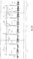
- embodiments are based on the finding that in the prior art, the periodic part is constructed using integer pitch lag, and that this creates a frequency shift of the harmonics and significant degradation in concealment of tonal signals with a constant pitch. This degradation can be seen in Fig. 8 , wherein Fig. 8 depicts a time-frequency representation of a speech signal being resynchronized when using a rounded pitch lag.
- Embodiments are moreover based on the finding that most of the problems of the prior art occur in situations as illustrated by the examples depicted in Figs. 6 and 7 , where d samples are removed.
- d samples are removed.
- the problem also occurs when there is a limit for d , but is not so obviously visible. Instead of continuously increasing the pitch, one would get a sudden increase followed by a sudden decrease of the pitch.
- Embodiments are based on the finding that this happens, because no samples are removed before and after the last pulse, indirectly also caused by not taking into account that the pulse T [ 2 ] moves within the frame after the removal of d samples. The wrong calculation of N also happens in this example.
- Embodiments provide improved concealment of monophonic signals, including speech, which is advantageous compared to the existing techniques described in the standards G.718 (see [ITU08a]) and G.729.1 (see [ITU06b]).
- the provided embodiments are suitable for signals with a constant pitch, as well as for signals with a changing pitch.
- a search concept for the pulses is provided that, in contrast to G.718 and G.729.1, takes into account the location of the first pulse in the calculation of the number of pulses in the constructed periodic part, denoted as N.
- an algorithm for searching for pulses is provided that, in contrast to G.718 and G.729.1, does not need the number of pulses in the constructed periodic part, denoted as N , that takes the location of the first pulse into account, and that directly calculates the last pulse index in the concealed frame, denoted as k.
- a pulse search is not needed.
- a construction of the periodic part is combined with the removal or addition of the samples, thus achieving less complexity than previous techniques.
- some embodiments provide the following changes for the above techniques as well as for the techniques of G.718 and G.729.1:
- Fig. 1 illustrates an apparatus for determining an estimated pitch lag according to an embodiment.
- the apparatus comprises an input interface 110 for receiving a plurality of original pitch lag values, and a pitch lag estimator 120 for estimating the estimated pitch lag.
- the pitch lag estimator 120 is configured to estimate the estimated pitch lag depending on a plurality of original pitch lag values and depending on a plurality of information values, wherein for each original pitch lag value of the plurality of original pitch lag values, an information value of the plurality of information values is assigned to said original pitch lag value.
- the pitch lag estimator 120 may, e.g., be configured to estimate the estimated pitch lag depending on the plurality of original pitch lag values and depending on a plurality of pitch gain values as the plurality of information values, wherein for each original pitch lag value of the plurality of original pitch lag values, a pitch gain value of the plurality of pitch gain values is assigned to said original pitch lag value.
- each of the plurality of pitch gain values may, e.g., be an adaptive codebook gain.
- the pitch lag estimator 120 may, e.g., be configured to estimate the estimated pitch lag by minimizing an error function.
- the pitch lag estimator 120 may, e.g., be configured to estimate the estimated pitch lag depending on the plurality of original pitch lag values and depending on a plurality of time values as the plurality of information values, wherein for each original pitch lag value of the plurality of original pitch lag values, a time value of the plurality of time values is assigned to said original pitch lag value.
- the pitch lag estimator 120 may, e.g., be configured to estimate the estimated pitch lag by minimizing an error function.
- weighted pitch prediction embodiments employing weighting according to the pitch gain are described with reference to formulae (20) - (22c). According to some of these embodiments, to overcome the drawback of the prior art, the pitch lags are weighted with the pitch gain to perform the pitch prediction.
- the pitch gain may be the adaptive-codebook gain g p as defined in the standard G.729 (see [ITU12], in particular chapter 3.7.3, more particularly formula (43)).
- the pitch gain may be the adaptive-codebook gain g p as defined in the standard G.718 (see [ITU08a], in particular chapter 6.8.4.1.4.1, more particularly formula (170)).
- the pitch lags may, e.g., be weighted with the pitch gain, for example, prior to performing the pitch prediction.
- a second buffer of length 8 may, for example, be introduced holding the pitch gains, which are taken at the same subframes as the pitch lags.
- the buffer may, e.g., be updated using the exact same rules as the update of the pitch lags.
- One possible realization is to update both buffers (holding pitch lags and pitch gains of the last eight subframes) at the end of each frame, regardless whether this frame was error free or error prone.
- Some embodiments provide significant inventive improvements of the prediction strategy of the G.718 standard.
- the buffers may be multiplied with each other element wise, in order to weight the pitch lag with a high factor if the associated pitch gain is high, and to weight it with a low factor if the associated pitch gain is low.
- the pitch prediction is performed like usual (see [ITU08a, section 7.11.1.3] for details on G.718).
- Some embodiments provide significant inventive improvements of the prediction strategy of the G.729.1 standard.
- the algorithm used in G.729.1 to predict the pitch (see [ITU06b] for details on G.729.1) is modified according to embodiments in order to use weighted prediction.
- g p ( i ) is representing the weighting factor.
- each g p ( i ) is representing a pitch gain from one of the past subframes.
- equations according to embodiments are provided, which describe how to derive the factors a and b, which could be used to predict the pitch lag according to: a + i ⁇ b, where i is the subframe number of the subframe to be predicted.
- A, B, C, D; E, F, G, H, I, J and K may, e.g., have the following values:
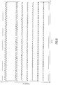
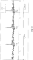
- Fig. 10 and Fig. 11 show the superior performance of the proposed pitch extrapolation.
- Fig. 10 illustrates a pitch lag diagram, wherein the pitch lag is reconstructed employing state of the art concepts.
- Fig. 11 illustrates a pitch lag diagram, wherein the pitch lag is reconstructed according to embodiments.
- Fig. 10 illustrates the performance of the prior art standards G.718 and G.729.1
- Fig. 11 illustrates the performance of a provided concept provided by an embodiment.
- the abscissa axis denotes the subframe number.
- the continuous line 1010 shows the encoder pitch lag which is embedded in the bitstream, and which is lost in the area of the grey segment 1030.
- the left ordinate axis represents a pitch lag axis.
- the right ordinate axis represents a pitch gain axis.
- the continuous line 1010 illustrates the pitch lag, while the dashed lines 1021, 1022, 1023 illustrate the pitch gain.
- the grey rectangle 1030 denotes the frame loss. Because of the frame loss that occurred in the area of the grey segment 1030, information on the pitch lag and pitch gain in this area is not available at the decoder side and has to be reconstructed.
- the pitch lag being concealed using the G.718 standard is illustrated by the dashed-dotted line portion 1011.
- the pitch lag being concealed using the G.729.1 standard is illustrated by the continuous line portion 1012. It can be clearly seen, that using the provided pitch prediction ( Fig. 11 , continuous line portion 1013) corresponds essentially to the lost encoder pitch lag and is thus advantageous over the G.718 and G.729.1 techniques.
- Some embodiments may, e.g., put high weights to more recent lags and less weight to lags being received longer ago.
- formula (21a) may then be employed to derive a and b.
- some embodiments may, e.g., conduct the prediction based on the last five subframes, P (0)... P (4).
- Fig. 2a illustrates an apparatus for reconstructing a frame comprising a speech signal as a reconstructed frame according to an embodiment.
- Said reconstructed frame is associated with one or more available frames, said one or more available frames being at least one of one or more preceding frames of the reconstructed frame and one or more succeeding frames of the reconstructed frame, wherein the one or more available frames comprise one or more pitch cycles as one or more available pitch cycles.
- the apparatus comprises a determination unit 210 for determining a sample number difference ( ⁇ 0 p ; ⁇ i ; ⁇ k + 1 p ) indicating a difference between a number of samples of one of the one or more available pitch cycles and a number of samples of a first pitch cycle to be reconstructed.
- the apparatus comprises a frame reconstructor for reconstructing the reconstructed frame by reconstructing, depending on the sample number difference ( ⁇ 0 p ; ⁇ i ; ⁇ k + 1 p ) and depending on the samples of said one of the one or more available pitch cycles, the first pitch cycle to be reconstructed as a first reconstructed pitch cycle.
- the frame reconstructor 220 is configured to reconstruct the reconstructed frame, such that the reconstructed frame completely or partially comprises the first reconstructed pitch cycle, such that the reconstructed frame completely or partially comprises a second reconstructed pitch cycle, and such that the number of samples of the first reconstructed pitch cycle differs from a number of samples of the second reconstructed pitch cycle.
- Reconstructing a pitch cycle is conducted by reconstructing some or all of the samples of the pitch cycle that shall be reconstructed. If the pitch cycle to be reconstructed is completely comprised by a frame that is lost, then all of the samples of the pitch cycle may, e.g., have to be reconstructed. If the pitch cycle to be reconstructed is only partially comprised by the frame that is lost, and if some the samples of the pitch cycle are available, e.g., as they are comprised another frame, than it may, e.g., be sufficient to only reconstruct the samples of the pitch cycle that are comprised by the frame that is lost to reconstruct the pitch cycle.
- Fig. 2b illustrates the functionality of the apparatus of Fig. 2a .
- Fig. 2b illustrates a speech signal 222 comprising the pulses 211, 212, 213, 214, 215, 216, 217.
- a first portion of the speech signal 222 is comprised by a frame n-1.
- a second portion of the speech signal 222 is comprised by a frame n.
- a third portion of the speech signal 222 is comprised by a frame n+1.
- frame n-1 is preceding frame n and frame n+1 is succeeding frame n.
- frame n-1 comprises a portion of the speech signal that occurred earlier in time compared to the portion of the speech signal of frame n; and frame n+1 comprises a portion of the speech signal that occurred later in time compared to the portion of the speech signal of frame n.
- a pitch cycle may, for example, be defined as follows: A pitch cycle starts with one of the pulses 211, 212, 213, etc. and ends with the immediately succeeding pulse in the speech signal.
- pulse 211 and 212 define the pitch cycle 201.
- Pulse 212 and 213 define the pitch cycle 202.
- Pulse 213 and 214 define the pitch cycle 203, etc.
- frame n is not available at a receiver or is corrupted.
- the receiver is aware of the pulses 211 and 212 and of the pitch cycle 201 of frame n-1.
- the receiver is aware of the pulses 216 and 217 and of the pitch cycle 206 of frame n+1.
- frame n which comprises the pulses 213, 214 and 215, which completely comprises the pitch cycles 203 and 204 and which partially comprises the pitch cycles 202 and 205, has to be reconstructed.
- frame n may be reconstructed depending on the samples of at least one pitch cycle ("available pitch cylces") of the available frames (e.g., preceding frame n-1 or succeeding frame n+1).
- the samples of the pitch cycle 201 of frame n-1 may, e.g., cyclically repeatedly copied to reconstruct the samples of the lost or corrupted frame.
- samples from the end of the frame n-1 are copied.
- the length of the portion of the n-1 st frame that is copied is equal to the length of the pitch cycle 201 (or almost equal). But the samples from both 201 and 202 are used for copying. This may be especially carefully considered when there is just one pulse in the n-1 st frame.
- the copied samples are modified.
- the present invention is moreover based on the finding that by cyclically repeatedly copying the samples of a pitch cycle, the pulses 213, 214, 215 of the lost frame n move to wrong positions, when the size of the pitch cycles that are (completely or partially) comprised by the lost frame (n) (pitch cycles 202, 203, 204 and 205) differs from the size of the copied available pitch cycle (here: pitch cycle 201).
- the difference between pitch cycle 201 and pitch cycle 202 is indicated by ⁇ 1
- the difference between pitch cycle 201 and pitch cycle 203 is indicated by ⁇ 2
- the difference between pitch cycle 201 and pitch cycle 204 is indicated by ⁇ 3
- the difference between pitch cycle 201 and pitch cycle 205 is indicated by ⁇ 4 .
- pitch cycle 201 of frame n-1 is significantly greater than pitch cycle 206.
- the pitch cycles 202, 203, 204 and 205 being (partially or completely) comprised by frame n and, are each smaller than pitch cycle 201 and greater than pitch cycle 206.
- the pitch cycles being closer to the large pitch cycle 201 are larger than the pitch cycles (e.g., pitch cycle 205) being closer to the small pitch cycle 206.
- the frame reconstructor 220 is configured to reconstruct the reconstructed frame such that the number of samples of the first reconstructed pitch cycle differs from a number of samples of a second reconstructed pitch cycle being partially or completely comprised by the reconstructed frame.
- the reconstruction of the frame depends on a sample number difference indicating a difference between a number of samples of one of the one or more available pitch cycles (e.g., pitch cycle 201) and a number of samples of a first pitch cycle (e.g., pitch cycle 202, 203, 204, 205) that shall be reconstructed.
- a sample number difference indicating a difference between a number of samples of one of the one or more available pitch cycles (e.g., pitch cycle 201) and a number of samples of a first pitch cycle (e.g., pitch cycle 202, 203, 204, 205) that shall be reconstructed.
- the samples of pitch cycle 201 may, e.g., be cyclically repeatedly copied.
- the sample number difference indicates how many samples shall be deleted from the cyclically repeated copy corresponding to the first pitch cycle to be reconstructed, or how many samples shall be added to the cyclically repeated copy corresponding to the first pitch cycle to be reconstructed.
- each sample number indicates how many samples shall be deleted from the cyclically repeated copy.
- the sample number may indicate how many samples shall be added to the cyclically repeated copy.
- samples may be added by adding samples with amplitude zero to the corresponding pitch cycle.
- samples may be added to the pitch cycle by coping other samples of the pitch cycle, e.g., by copying samples being neighboured to the positions of the samples to be added.
- samples of a pitch cycle of a frame preceding the lost or corrupted frame have been cyclically repeatedly copied
- samples of a pitch cycle of a frame succeeding the lost or corrupted frame are cyclically repeatedly copied to reconstruct the lost frame.
- Such a sample number difference may be determined for each pitch cycle to be reconstructed. Then, the sample number difference of each pitch cycle indicates how many samples shall be deleted from the cyclically repeated copy corresponding to the corresponding pitch cycle to be reconstructed, or how many samples shall be added to the cyclically repeated copy corresponding to the corresponding pitch cycle to be reconstructed.
- the determination unit 210 may, e.g., be configured to determine a sample number difference for each of a plurality of pitch cycles to be reconstructed, such that the sample number difference of each of the pitch cycles indicates a difference between the number of samples of said one of the one or more available pitch cycles and a number of samples of said pitch cycle to be reconstructed.
- the frame reconstructor 220 may, e.g., be configured to reconstruct each pitch cycle of the plurality of pitch cycles to be reconstructed depending on the sample number difference of said pitch cycle to be reconstructed and depending on the samples of said one of the one or more available pitch cycles, to reconstruct the reconstructed frame.
- the frame reconstructor 220 may, e.g., be configured to generate an intermediate frame depending on said one of the of the one or more available pitch cycles.
- the frame reconstructor 220 may, e.g., be configured to modify the intermediate frame to obtain the reconstructed frame.
- the determination unit 210 may, e.g., be configured to determine a frame difference value ( d; s ) indicating how many samples are to be removed from the intermediate frame or how many samples are to be added to the intermediate frame.
- the frame reconstructor 220 may, e.g., be configured to remove first samples from the intermediate frame to obtain the reconstructed frame, when the frame difference value indicates that the first samples shall be removed from the frame.
- the frame reconstructor 220 may, e.g., be configured to add second samples to the intermediate frame to obtain the reconstructed frame, when the frame difference value ( d ; s ) indicates that the second samples shall be added to the frame.
- the frame reconstructor 220 may, e.g., be configured to remove the first samples from the intermediate frame when the frame difference value indicates that the first samples shall be removed from the frame, so that the number of first samples that are removed from the intermediate frame is indicated by the frame difference value. Moreover, the frame reconstructor 220 may, e.g., be configured to add the second samples to the intermediate frame when the frame difference value indicates that the second samples shall be added to the frame, so that the number of second samples that are added to the intermediate frame is indicated by the frame difference value.
- the frame reconstructor 220 may, e.g., be adapted to generate an intermediate frame depending on said one of the one or more available pitch cycles. Moreover, the frame reconstructor 220 may, e.g., be adapted to generate the intermediate frame so that the intermediate frame comprises a first partial intermediate pitch cycle, one or more further intermediate pitch cylces, and a second partial intermediate pitch cycle.
- the first partial intermediate pitch cycle may, e.g., depend on one or more of the samples of said one of the one or more available pitch cycles, wherein each of the one or more further intermediate pitch cycles depends on all of the samples of said one of the one or more available pitch cycles, and wherein the second partial intermediate pitch cycle depends on one or more of the samples of said one of the one or more available pitch cycles.
- the determination unit 210 may, e.g., be configured to determine a start portion difference number indicating how many samples are to be removed or added from the first partial intermediate pitch cycle, and wherein the frame reconstructor 220 is configured to remove one or more first samples from the first partial intermediate pitch cycle, or is configured to add one or more first samples to the first partial intermediate pitch cycle depending on the start portion difference number.
- the determination unit 210 may, e.g., be configured to determine for each of the further intermediate pitch cycles a pitch cycle difference number indicating how many samples are to be removed or added from said one of the further intermediate pitch cycles.
- the frame reconstructor 220 may, e.g., be configured to remove one or more second samples from said one of the further intermediate pitch cycles, or is configured to add one or more second samples to said one of the further intermediate pitch cycles depending on said pitch cycle difference number.
- the determination unit 210 may, e.g., be configured to determine an end portion difference number indicating how many samples are to be removed or added from the second partial intermediate pitch cycle, and wherein the frame reconstructor 220 is configured to remove one or more third samples from the second partial intermediate pitch cycle, or is configured to add one or more third samples to the second partial intermediate pitch cycle depending on the end portion difference number.
- the frame reconstructor 220 may, e.g., be configured to generate an intermediate frame depending on said one of the of the one or more available pitch cycles.
- the determination unit 210 may, e.g., be adapted to determine one or more low energy signal portions of the speech signal comprised by the intermediate frame, wherein each of the one or more low energy signal portions is a first signal portion of the speech signal within the intermediate frame, where the energy of the speech signal is lower than in a second signal portion of the speech signal comprised by the intermediate frame.
- the frame reconstructor 220 may, e.g., be configured to remove one or more samples from at least one of the one or more low energy signal portions of the speech signal, or to add one or more samples to at least one of the one or more low energy signal portions of the speech signal, to obtain the reconstructed frame.
- the frame reconstructor 220 may, e.g., be configured to generate the intermediate frame, such that the intermediate frame comprises one or more reconstructed pitch cycles, such that each of the one or more reconstructed pitch cylces depends on said one of the of the one or more available pitch cycles.
- the determination unit 210 may, e.g., be configured to determine a number of samples that shall be removed from each of the one or more reconstructed pitch cycles.
- the determination unit 210 may, e.g., be configured to determine each of the one or more low energy signal portions such that for each of the one or more low energy signal portions a number of samples of said low energy signal portion depends on the number of samples that shall be removed from one of the one or more reconstructed pitch cycles, wherein said low energy signal portion is located within said one of the one or more reconstructed pitch cycles.
- the determination unit 210 may, e.g., be configured to determine a position of one or more pulses of the speech signal of the frame to be reconstructed as reconstructed frame.
- the frame reconstructor 220 may, e.g., be configured to reconstruct the reconstructed frame depending on the position of the one or more pulses of the speech signal.
- the last pitch lag is used without rounding, preserving the fractional part.
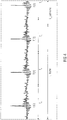
- the periodic part is constructed using the non-integer pitch and interpolation as for example in [MTTA90]. This will reduce the frequency shift of the harmonics, compared to using the rounded pitch lag and thus significantly improve concealment of tonal or voiced signals with constant pitch.
- Fig. 8 illustrates a time-frequency representation of a speech signal being resynchronized using a rounded pitch lag.
- Fig. 9 illustrates a time-frequency representation of a speech signal being resynchronized using a non-rounded pitch lag with the fractional part.
- d being the difference, between the sum of the total number of samples within pitch cycles with the constant pitch ( T c ) and the sum of the total number of samples within pitch cycles with the evolving pitch p[i].
- T c round ( last_pitch ) .
- the difference, d may be determined using a faster and more precise algorithm (fast algorithm for determining d approach) as described in the following.
- Such an algorithm may, e.g., be based on the following principles:
- no rounding is conducted and a fractional pitch is used. Then:
- rounding is conducted.
- M the number of subframes in a frame
- an algorithm for calculating d accordingly:
- N 1 + ⁇ L_frame ⁇ T 0 T c ⁇ and the last pulse has then the index N - 1.
- N may be calculated for the examples illustrated by Fig. 4 and Fig. 5 .
- Actual last pulse position in the constructed periodic part of the excitation determines the number of the full pitch cycles k , where samples are removed (or added).
- Fig. 12 illustrates a position of the last pulse T [2] before removing d samples.
- reference sign 1210 denotes d .
- the index of the last pulse k is 2 and there are 2 full pitch cycles from which the samples should be removed.
- a codec that, e.g., uses frames of at least 20 ms and, where the lowest fundamental frequency of speech is, e.g., at least 40 Hz, in most cases at least one pulse exists in the concealed frame other than UNVOICED.
- ⁇ i ⁇ + i ⁇ 1 a , 1 ⁇ i ⁇ k , where a is an unknown variable that needs to be expressed in terms of the known variables.
- ⁇ 0 ⁇ ⁇ a T 0 T c
- ⁇ k+1 ⁇ + ka L + d ⁇ T k T c
- Each of the ⁇ i values is a sample number difference.
- ⁇ 0 is a sample number difference.
- ⁇ k +1 is a sample number difference.
- Fig. 13 illustrates the speech signal of Fig. 12 , additionally illustrating ⁇ 0 to ⁇ 3 .
- reference sign 1210 denotes d.
- the samples are removed or added in the minimum energy regions.
- ⁇ 0 ⁇ ⁇ a T 0 T c
- ⁇ and a are unknown variables that need to be expressed in terms of the known variables.
- t [ i ] denotes the length of the i th pitch cycle.
- ( k + 1) ⁇ samples are removed in the k th pitch cycle.
- ( i + 1) ⁇ samples are removed at the position of the minimum energy. There is no need to know the location of pulses, as the search for the minimum energy position is done in the circular buffer that holds one pitch cycle.
- the minimum energy region would appear after the first pulse more likely, if the pulse is closer to the concealed frame beginning. If the first pulse is closer to the concealed frame beginning, it is more likely that the last pitch cycle in the last received frame is larger than T c . To reduce the possibility of the discontinuity in the pitch change, weighting should be used to give advantage to minimum regions closer to the beginning or to the end of the pitch cycle.
- the equivalent procedure can be used by taking into account that d ⁇ 0 and ⁇ ⁇ 0 and that we add in total
- the fractional pitch can be used at the subframe level to derive d as described above with respect to the "fast algorithm for determining d approach", as anyhow the approximated pitch cycle lengths are used.
- embodiments of the present invention may employ the definitions provided for these parameters with respect to the first group of pulse resynchronization embodiments defined above (see formulae (25) - (63)).
- Some of the formulae (64) - (113) of the second group of pulse resynchronization embodiments may redefine some of the parameters already used with respect to the first group of pulse resynchronization embodiments. In this case, the provided redefined definitions apply for the second pulse resynchronization embodiments.
- T [0] is the location of the first maximum pulse in the constructed periodic part of the excitation.
- the glottal pulse resynchronization is performed to correct the difference between the estimated target position of the last pulse in the lost frame (P), and its actual position in the constructed periodic part of the excitation ( T [ k ]) .
- the estimated target position of the last pulse in the lost frame (P) may, for example, be determined indirectly by the estimation of the pitch lag evolution.
- the pitch lag evolution is, for example, extrapolated based on the pitch lags of the last seven subframes before the lost frame.
- the pitch extrapolation can be done, for example, using weighted linear fitting or the method from G.718 or the method from G.729.1 or any other method for the pitch interpolation that, e.g., takes one or more pitches from future frames into account.
- the pitch extrapolation can also be non-linear.
- T ext may be determined in the same way as T ext is determined above.
- T ext > T p then s samples should be added to a frame, and if T ext ⁇ T p then - s samples should be removed from a frame. After adding or removing
- the glottal pulse resynchronization is done by adding or removing samples in the minimum energy regions of all of the pitch cycles.
- the difference, s may, for example, be calculated based on the following principles:
- the actual last pulse position in the constructed periodic part of the excitation determines the number of the full pitch cycles k , where samples are removed (or added).
- Fig. 12 illustrates a speech signal before removing samples.
- the index of the last pulse k is 2 and there are two full pitch cycles from which the samples should be removed.
- reference sign 1210 denotes
- ⁇ i ⁇ + i ⁇ 1 a , 1 ⁇ i ⁇ k and where a is an unknown variable that may, e.g., be expressed in terms of the known variables.
- Fig. 13 illustrates a schematic representation of samples removed in each pitch cycle.
- reference sign 1210 denotes
- the samples may, e.g., be removed or added in the minimum energy regions.
- ⁇ 0 p , ⁇ i and ⁇ k + 1 p are positive and that the sign of s determines if the samples are to be added or removed.
- ⁇ 0 p , ⁇ i and ⁇ k + 1 p may, e.g., be rounded.
- other concepts using waveform interpolation may, e.g., alternatively or additionally be used to avoid the rounding, but with the increased complexity.
- input parameters of such an algorithm may, for example, be: L - Frame length M - Number of subframes T p - Pitch cycle length at the end of the last received frame T ext - Pitch cycle length at the end of the concealed frame src_exc - Input excitation signal that was created copying the low pass filtered last pitch cycle of the excitation signal from the end of the last received frame as described above.
- such an algorithm may comprise, one or more or all of the following steps:
- Fig. 2c illustrates a system for reconstructing a frame comprising a speech signal according to an embodiment.
- the system comprises an apparatus 100 for determining an estimated pitch lag according to one of the above-described embodiments, and an apparatus 200 for reconstructing the frame, wherein the apparatus for reconstructing the frame is configured to reconstruct the frame depending on the estimated pitch lag.
- the estimated pitch lag is a pitch lag of the speech signal.
- the reconstructed frame may, e.g., be associated with one or more available frames, said one or more available frames being at least one of one or more preceding frames of the reconstructed frame and one or more succeeding frames of the reconstructed frame, wherein the one or more available frames comprise one or more pitch cycles as one or more available pitch cycles.
- the apparatus 200 for reconstructing the frame may, e.g., be an apparatus for reconstructing a frame according to one of the above-described embodiments.
- aspects have been described in the context of an apparatus, it is clear that these aspects also represent a description of the corresponding method, where a block or device corresponds to a method step or a feature of a method step. Analogously, aspects described in the context of a method step also represent a description of a corresponding block or item or feature of a corresponding apparatus.
- the inventive decomposed signal can be stored on a digital storage medium or can be transmitted on a transmission medium such as a wireless transmission medium or a wired transmission medium such as the Internet.
- embodiments of the invention can be implemented in hardware or in software.
- the implementation can be performed using a digital storage medium, for example a floppy disk, a DVD, a CD, a ROM, a PROM, an EPROM, an EEPROM or a FLASH memory, having electronically readable control signals stored thereon, which cooperate (or are capable of cooperating) with a programmable computer system such that the respective method is performed.
- a digital storage medium for example a floppy disk, a DVD, a CD, a ROM, a PROM, an EPROM, an EEPROM or a FLASH memory, having electronically readable control signals stored thereon, which cooperate (or are capable of cooperating) with a programmable computer system such that the respective method is performed.
- Some embodiments according to the invention comprise a non-transitory data carrier having electronically readable control signals, which are capable of cooperating with a programmable computer system, such that one of the methods described herein is performed.
- embodiments of the present invention can be implemented as a computer program product with a program code, the program code being operative for performing one of the methods when the computer program product runs on a computer.
- the program code may for example be stored on a machine readable carrier.
- inventions comprise the computer program for performing one of the methods described herein, stored on a machine readable carrier.
- an embodiment of the inventive method is, therefore, a computer program having a program code for performing one of the methods described herein, when the computer program runs on a computer.
- a further embodiment of the inventive methods is, therefore, a data carrier (or a digital storage medium, or a computer-readable medium) comprising, recorded thereon, the computer program for performing one of the methods described herein.
- a further embodiment of the inventive method is, therefore, a data stream or a sequence of signals representing the computer program for performing one of the methods described herein.
- the data stream or the sequence of signals may for example be configured to be transferred via a data communication connection, for example via the Internet.
- a further embodiment comprises a processing means, for example a computer, or a programmable logic device, configured to or adapted to perform one of the methods described herein.
- a processing means for example a computer, or a programmable logic device, configured to or adapted to perform one of the methods described herein.
- a further embodiment comprises a computer having installed thereon the computer program for performing one of the methods described herein.
- a programmable logic device for example a field programmable gate array
- a field programmable gate array may cooperate with a microprocessor in order to perform one of the methods described herein.
- the methods are preferably performed by any hardware apparatus.
Landscapes
- Engineering & Computer Science (AREA)
- Physics & Mathematics (AREA)
- Computational Linguistics (AREA)
- Signal Processing (AREA)
- Health & Medical Sciences (AREA)
- Audiology, Speech & Language Pathology (AREA)
- Human Computer Interaction (AREA)
- Acoustics & Sound (AREA)
- Multimedia (AREA)
- General Physics & Mathematics (AREA)
- Algebra (AREA)
- Mathematical Analysis (AREA)
- Mathematical Optimization (AREA)
- Mathematical Physics (AREA)
- Pure & Applied Mathematics (AREA)
- Theoretical Computer Science (AREA)
- Compression, Expansion, Code Conversion, And Decoders (AREA)
- Mobile Radio Communication Systems (AREA)
- Financial Or Insurance-Related Operations Such As Payment And Settlement (AREA)
- Measurement Of Mechanical Vibrations Or Ultrasonic Waves (AREA)
Priority Applications (1)
| Application Number | Priority Date | Filing Date | Title |
|---|---|---|---|
| EP24167537.0A EP4375993A2 (de) | 2013-06-21 | 2014-06-16 | Vorrichtung und verfahren zur verbesserten maskierung des adaptiven codebuchs bei der acelp-artigen maskierung unter verwendung verbesserter tonhöhenverzögerungsschätzung |
Applications Claiming Priority (4)
| Application Number | Priority Date | Filing Date | Title |
|---|---|---|---|
| EP13173157 | 2013-06-21 | ||
| EP14166990 | 2014-05-05 | ||
| PCT/EP2014/062589 WO2014202539A1 (en) | 2013-06-21 | 2014-06-16 | Apparatus and method for improved concealment of the adaptive codebook in acelp-like concealment employing improved pitch lag estimation |
| EP14729939.0A EP3011554B1 (de) | 2013-06-21 | 2014-06-16 | Schätzung der tonhöhenverzögerung |
Related Parent Applications (2)
| Application Number | Title | Priority Date | Filing Date |
|---|---|---|---|
| EP14729939.0A Division EP3011554B1 (de) | 2013-06-21 | 2014-06-16 | Schätzung der tonhöhenverzögerung |
| EP14729939.0A Division-Into EP3011554B1 (de) | 2013-06-21 | 2014-06-16 | Schätzung der tonhöhenverzögerung |
Related Child Applications (1)
| Application Number | Title | Priority Date | Filing Date |
|---|---|---|---|
| EP24167537.0A Division EP4375993A2 (de) | 2013-06-21 | 2014-06-16 | Vorrichtung und verfahren zur verbesserten maskierung des adaptiven codebuchs bei der acelp-artigen maskierung unter verwendung verbesserter tonhöhenverzögerungsschätzung |
Publications (2)
| Publication Number | Publication Date |
|---|---|
| EP3540731A2 true EP3540731A2 (de) | 2019-09-18 |
| EP3540731A3 EP3540731A3 (de) | 2019-10-30 |
Family
ID=50942300
Family Applications (3)
| Application Number | Title | Priority Date | Filing Date |
|---|---|---|---|
| EP19172360.0A Pending EP3540731A3 (de) | 2013-06-21 | 2014-06-16 | Schätzung der tonhöhenverzögerung |
| EP14729939.0A Active EP3011554B1 (de) | 2013-06-21 | 2014-06-16 | Schätzung der tonhöhenverzögerung |
| EP24167537.0A Pending EP4375993A2 (de) | 2013-06-21 | 2014-06-16 | Vorrichtung und verfahren zur verbesserten maskierung des adaptiven codebuchs bei der acelp-artigen maskierung unter verwendung verbesserter tonhöhenverzögerungsschätzung |
Family Applications After (2)
| Application Number | Title | Priority Date | Filing Date |
|---|---|---|---|
| EP14729939.0A Active EP3011554B1 (de) | 2013-06-21 | 2014-06-16 | Schätzung der tonhöhenverzögerung |
| EP24167537.0A Pending EP4375993A2 (de) | 2013-06-21 | 2014-06-16 | Vorrichtung und verfahren zur verbesserten maskierung des adaptiven codebuchs bei der acelp-artigen maskierung unter verwendung verbesserter tonhöhenverzögerungsschätzung |
Country Status (18)
| Country | Link |
|---|---|
| US (3) | US10381011B2 (de) |
| EP (3) | EP3540731A3 (de) |
| JP (4) | JP6482540B2 (de) |
| KR (2) | KR102120073B1 (de) |
| CN (2) | CN111862998A (de) |
| AU (2) | AU2014283393A1 (de) |
| BR (2) | BR112015031181A2 (de) |
| CA (1) | CA2915805C (de) |
| ES (1) | ES2746322T3 (de) |
| HK (1) | HK1224427A1 (de) |
| MX (1) | MX371425B (de) |
| MY (1) | MY177559A (de) |
| PL (1) | PL3011554T3 (de) |
| PT (1) | PT3011554T (de) |
| RU (1) | RU2665253C2 (de) |
| SG (1) | SG11201510463WA (de) |
| TW (2) | TWI711033B (de) |
| WO (1) | WO2014202539A1 (de) |
Families Citing this family (7)
| Publication number | Priority date | Publication date | Assignee | Title |
|---|---|---|---|---|
| EP3011555B1 (de) | 2013-06-21 | 2018-03-28 | Fraunhofer-Gesellschaft zur Förderung der angewandten Forschung e.V. | Wiederherstellung eines sprachrahmens |
| BR112015031181A2 (pt) * | 2013-06-21 | 2017-07-25 | Fraunhofer Ges Forschung | aparelho e método que realizam conceitos aperfeiçoados para tcx ltp |
| ES2746034T3 (es) | 2013-10-31 | 2020-03-04 | Fraunhofer Ges Forschung | Decodificador de audio y método para proporcionar una información de audio decodificada usando un ocultamiento de error sobre la base de una señal de excitación de dominio de tiempo |
| CA2928974C (en) | 2013-10-31 | 2020-06-02 | Jeremie Lecomte | Audio decoder and method for providing a decoded audio information using an error concealment modifying a time domain excitation signal |
| MX2018010754A (es) | 2016-03-07 | 2019-01-14 | Fraunhofer Ges Forschung | Unidad de ocultamiento de error, decodificador de audio y método relacionado y programa de computadora que desaparece una trama de audio ocultada de acuerdo con factores de amortiguamiento diferentes para bandas de frecuencia diferentes. |
| CA3016837C (en) | 2016-03-07 | 2021-09-28 | Fraunhofer-Gesellschaft Zur Foerderung Der Angewandten Forschung E.V. | Hybrid concealment method: combination of frequency and time domain packet loss concealment in audio codecs |
| MX2018010756A (es) | 2016-03-07 | 2019-01-14 | Fraunhofer Ges Forschung | Unidad de ocultamiento de error, decodificador de audio, y método relacionado y programa de computadora que usa características de una representación decodificada de una trama de audio decodificada apropiadamente. |
Citations (1)
| Publication number | Priority date | Publication date | Assignee | Title |
|---|---|---|---|---|
| US8255207B2 (en) | 2005-12-28 | 2012-08-28 | Voiceage Corporation | Method and device for efficient frame erasure concealment in speech codecs |
Family Cites Families (64)
| Publication number | Priority date | Publication date | Assignee | Title |
|---|---|---|---|---|
| US5179594A (en) * | 1991-06-12 | 1993-01-12 | Motorola, Inc. | Efficient calculation of autocorrelation coefficients for CELP vocoder adaptive codebook |
| US5187745A (en) * | 1991-06-27 | 1993-02-16 | Motorola, Inc. | Efficient codebook search for CELP vocoders |
| US5621852A (en) * | 1993-12-14 | 1997-04-15 | Interdigital Technology Corporation | Efficient codebook structure for code excited linear prediction coding |
| KR960009530B1 (en) | 1993-12-20 | 1996-07-20 | Korea Electronics Telecomm | Method for shortening processing time in pitch checking method for vocoder |
| EP0744069B1 (de) | 1994-02-01 | 2002-06-05 | QUALCOMM Incorporated | Lineare vorhersage durch impulsanregung |
| US5792072A (en) * | 1994-06-06 | 1998-08-11 | University Of Washington | System and method for measuring acoustic reflectance |
| US5781880A (en) * | 1994-11-21 | 1998-07-14 | Rockwell International Corporation | Pitch lag estimation using frequency-domain lowpass filtering of the linear predictive coding (LPC) residual |
| US5751905A (en) * | 1995-03-15 | 1998-05-12 | International Business Machines Corporation | Statistical acoustic processing method and apparatus for speech recognition using a toned phoneme system |
| US5699485A (en) * | 1995-06-07 | 1997-12-16 | Lucent Technologies Inc. | Pitch delay modification during frame erasures |
| US5946650A (en) * | 1997-06-19 | 1999-08-31 | Tritech Microelectronics, Ltd. | Efficient pitch estimation method |
| US6556966B1 (en) * | 1998-08-24 | 2003-04-29 | Conexant Systems, Inc. | Codebook structure for changeable pulse multimode speech coding |
| US6507814B1 (en) * | 1998-08-24 | 2003-01-14 | Conexant Systems, Inc. | Pitch determination using speech classification and prior pitch estimation |
| US6449590B1 (en) | 1998-08-24 | 2002-09-10 | Conexant Systems, Inc. | Speech encoder using warping in long term preprocessing |
| US7072832B1 (en) * | 1998-08-24 | 2006-07-04 | Mindspeed Technologies, Inc. | System for speech encoding having an adaptive encoding arrangement |
| US6456964B2 (en) * | 1998-12-21 | 2002-09-24 | Qualcomm, Incorporated | Encoding of periodic speech using prototype waveforms |
| US6782360B1 (en) * | 1999-09-22 | 2004-08-24 | Mindspeed Technologies, Inc. | Gain quantization for a CELP speech coder |
| CN1432176A (zh) * | 2000-04-24 | 2003-07-23 | 高通股份有限公司 | 用于预测量化有声语音的方法和设备 |
| US6584438B1 (en) * | 2000-04-24 | 2003-06-24 | Qualcomm Incorporated | Frame erasure compensation method in a variable rate speech coder |
| US6760698B2 (en) * | 2000-09-15 | 2004-07-06 | Mindspeed Technologies Inc. | System for coding speech information using an adaptive codebook with enhanced variable resolution scheme |
| SE519976C2 (sv) * | 2000-09-15 | 2003-05-06 | Ericsson Telefon Ab L M | Kodning och avkodning av signaler från flera kanaler |
| US7590525B2 (en) | 2001-08-17 | 2009-09-15 | Broadcom Corporation | Frame erasure concealment for predictive speech coding based on extrapolation of speech waveform |
| JP2003140699A (ja) * | 2001-11-07 | 2003-05-16 | Fujitsu Ltd | 音声復号化装置 |
| AU2003214182A1 (en) * | 2002-03-12 | 2003-09-29 | Dilithium Networks Pty Limited | Method for adaptive codebook pitch-lag computation in audio transcoders |
| CA2388439A1 (en) | 2002-05-31 | 2003-11-30 | Voiceage Corporation | A method and device for efficient frame erasure concealment in linear predictive based speech codecs |
| US6781880B2 (en) * | 2002-07-19 | 2004-08-24 | Micron Technology, Inc. | Non-volatile memory erase circuitry |
| US7137626B2 (en) | 2002-07-29 | 2006-11-21 | Intel Corporation | Packet loss recovery |
| KR100711280B1 (ko) | 2002-10-11 | 2007-04-25 | 노키아 코포레이션 | 소스 제어되는 가변 비트율 광대역 음성 부호화 방법 및장치 |
| US7613607B2 (en) * | 2003-12-18 | 2009-11-03 | Nokia Corporation | Audio enhancement in coded domain |
| CA2457988A1 (en) * | 2004-02-18 | 2005-08-18 | Voiceage Corporation | Methods and devices for audio compression based on acelp/tcx coding and multi-rate lattice vector quantization |
| CN1989548B (zh) * | 2004-07-20 | 2010-12-08 | 松下电器产业株式会社 | 语音解码装置及补偿帧生成方法 |
| US7860710B2 (en) * | 2004-09-22 | 2010-12-28 | Texas Instruments Incorporated | Methods, devices and systems for improved codebook search for voice codecs |
| UA90506C2 (ru) | 2005-03-11 | 2010-05-11 | Квелкомм Инкорпорейтед | Изменение масштаба времени кадров в вокодере с помощью изменения остатка |
| NZ562183A (en) * | 2005-04-01 | 2010-09-30 | Qualcomm Inc | Systems, methods, and apparatus for highband excitation generation |
| WO2006116024A2 (en) * | 2005-04-22 | 2006-11-02 | Qualcomm Incorporated | Systems, methods, and apparatus for gain factor attenuation |
| US7177804B2 (en) * | 2005-05-31 | 2007-02-13 | Microsoft Corporation | Sub-band voice codec with multi-stage codebooks and redundant coding |
| US7457746B2 (en) | 2006-03-20 | 2008-11-25 | Mindspeed Technologies, Inc. | Pitch prediction for packet loss concealment |
| WO2008007699A1 (en) | 2006-07-12 | 2008-01-17 | Panasonic Corporation | Audio decoding device and audio encoding device |
| US8532984B2 (en) * | 2006-07-31 | 2013-09-10 | Qualcomm Incorporated | Systems, methods, and apparatus for wideband encoding and decoding of active frames |
| WO2008022181A2 (en) * | 2006-08-15 | 2008-02-21 | Broadcom Corporation | Updating of decoder states after packet loss concealment |
| FR2907586A1 (fr) | 2006-10-20 | 2008-04-25 | France Telecom | Synthese de blocs perdus d'un signal audionumerique,avec correction de periode de pitch. |
| DK2102619T3 (en) | 2006-10-24 | 2017-05-15 | Voiceage Corp | METHOD AND DEVICE FOR CODING TRANSITION FRAMEWORK IN SPEECH SIGNALS |
| CN101046964B (zh) | 2007-04-13 | 2011-09-14 | 清华大学 | 基于重叠变换压缩编码的错误隐藏帧重建方法 |
| WO2008151408A1 (en) | 2007-06-14 | 2008-12-18 | Voiceage Corporation | Device and method for frame erasure concealment in a pcm codec interoperable with the itu-t recommendation g.711 |
| JP4928366B2 (ja) * | 2007-06-25 | 2012-05-09 | 日本電信電話株式会社 | ピッチ探索装置、パケット消失補償装置、それらの方法、プログラム及びその記録媒体 |
| US8527265B2 (en) | 2007-10-22 | 2013-09-03 | Qualcomm Incorporated | Low-complexity encoding/decoding of quantized MDCT spectrum in scalable speech and audio codecs |
| US8515767B2 (en) | 2007-11-04 | 2013-08-20 | Qualcomm Incorporated | Technique for encoding/decoding of codebook indices for quantized MDCT spectrum in scalable speech and audio codecs |
| CN101261833B (zh) | 2008-01-24 | 2011-04-27 | 清华大学 | 一种使用正弦模型进行音频错误隐藏处理的方法 |
| CN101335000B (zh) | 2008-03-26 | 2010-04-21 | 华为技术有限公司 | 编码的方法及装置 |
| CN102057424B (zh) | 2008-06-13 | 2015-06-17 | 诺基亚公司 | 用于经编码的音频数据的错误隐藏的方法和装置 |
| US8768690B2 (en) | 2008-06-20 | 2014-07-01 | Qualcomm Incorporated | Coding scheme selection for low-bit-rate applications |
| US8428938B2 (en) | 2009-06-04 | 2013-04-23 | Qualcomm Incorporated | Systems and methods for reconstructing an erased speech frame |
| DE102010027650A1 (de) * | 2009-07-17 | 2011-03-10 | Johnson Electric S.A. | Angetriebenes Werkzeug |
| EP3474279A1 (de) | 2009-07-27 | 2019-04-24 | Unified Sound Systems, Inc. | Verfahren und vorrichtungen zur verarbeitung eines tonsignals |
| CN102648493B (zh) * | 2009-11-24 | 2016-01-20 | Lg电子株式会社 | 音频信号处理方法和设备 |
| US8428936B2 (en) | 2010-03-05 | 2013-04-23 | Motorola Mobility Llc | Decoder for audio signal including generic audio and speech frames |
| ES2710554T3 (es) | 2010-07-08 | 2019-04-25 | Fraunhofer Ges Forschung | Codificador que utiliza cancelación del efecto de solapamiento hacia delante |
| US9082416B2 (en) * | 2010-09-16 | 2015-07-14 | Qualcomm Incorporated | Estimating a pitch lag |
| WO2012158159A1 (en) | 2011-05-16 | 2012-11-22 | Google Inc. | Packet loss concealment for audio codec |
| US8620646B2 (en) * | 2011-08-08 | 2013-12-31 | The Intellisis Corporation | System and method for tracking sound pitch across an audio signal using harmonic envelope |
| US8781880B2 (en) * | 2012-06-05 | 2014-07-15 | Rank Miner, Inc. | System, method and apparatus for voice analytics of recorded audio |
| CN103714821A (zh) | 2012-09-28 | 2014-04-09 | 杜比实验室特许公司 | 基于位置的混合域数据包丢失隐藏 |
| CN103272418B (zh) | 2013-05-28 | 2015-08-05 | 佛山市金凯地过滤设备有限公司 | 一种压滤机 |
| BR112015031181A2 (pt) | 2013-06-21 | 2017-07-25 | Fraunhofer Ges Forschung | aparelho e método que realizam conceitos aperfeiçoados para tcx ltp |
| EP3011555B1 (de) | 2013-06-21 | 2018-03-28 | Fraunhofer-Gesellschaft zur Förderung der angewandten Forschung e.V. | Wiederherstellung eines sprachrahmens |
-
2014
- 2014-06-16 BR BR112015031181A patent/BR112015031181A2/pt not_active IP Right Cessation
- 2014-06-16 BR BR112015031824-0A patent/BR112015031824B1/pt active IP Right Grant
- 2014-06-16 AU AU2014283393A patent/AU2014283393A1/en not_active Abandoned
- 2014-06-16 RU RU2016101599A patent/RU2665253C2/ru active
- 2014-06-16 EP EP19172360.0A patent/EP3540731A3/de active Pending
- 2014-06-16 CN CN202010573105.1A patent/CN111862998A/zh active Pending
- 2014-06-16 CN CN201480035427.3A patent/CN105408954B/zh active Active
- 2014-06-16 PL PL14729939T patent/PL3011554T3/pl unknown
- 2014-06-16 WO PCT/EP2014/062589 patent/WO2014202539A1/en active Application Filing
- 2014-06-16 KR KR1020167001881A patent/KR102120073B1/ko active IP Right Grant
- 2014-06-16 ES ES14729939T patent/ES2746322T3/es active Active
- 2014-06-16 PT PT147299390T patent/PT3011554T/pt unknown
- 2014-06-16 SG SG11201510463WA patent/SG11201510463WA/en unknown
- 2014-06-16 KR KR1020187010994A patent/KR20180042468A/ko not_active Application Discontinuation
- 2014-06-16 CA CA2915805A patent/CA2915805C/en active Active
- 2014-06-16 MX MX2015017833A patent/MX371425B/es active IP Right Grant
- 2014-06-16 MY MYPI2015002993A patent/MY177559A/en unknown
- 2014-06-16 JP JP2016520421A patent/JP6482540B2/ja active Active
- 2014-06-16 EP EP14729939.0A patent/EP3011554B1/de active Active
- 2014-06-16 EP EP24167537.0A patent/EP4375993A2/de active Pending
- 2014-06-20 TW TW106123342A patent/TWI711033B/zh active
- 2014-06-20 TW TW103121374A patent/TWI613642B/zh active
-
2015
- 2015-12-21 US US14/977,224 patent/US10381011B2/en active Active
-
2016
- 2016-10-27 HK HK16112359.2A patent/HK1224427A1/zh unknown
-
2018
- 2018-01-10 AU AU2018200208A patent/AU2018200208B2/en active Active
- 2018-12-06 JP JP2018228601A patent/JP7202161B2/ja active Active
-
2019
- 2019-06-18 US US16/445,052 patent/US11410663B2/en active Active
-
2021
- 2021-03-24 JP JP2021049334A patent/JP2021103325A/ja active Pending
-
2022
- 2022-06-30 US US17/810,132 patent/US20220343924A1/en active Pending
-
2023
- 2023-03-15 JP JP2023040193A patent/JP2023072050A/ja active Pending
Patent Citations (1)
| Publication number | Priority date | Publication date | Assignee | Title |
|---|---|---|---|---|
| US8255207B2 (en) | 2005-12-28 | 2012-08-28 | Voiceage Corporation | Method and device for efficient frame erasure concealment in speech codecs |
Non-Patent Citations (12)
Also Published As
Similar Documents
| Publication | Publication Date | Title |
|---|---|---|
| US10643624B2 (en) | Apparatus and method for improved concealment of the adaptive codebook in ACELP-like concealment employing improved pulse resynchronization | |
| US20220343924A1 (en) | Apparatus and method for improved concealment of the adaptive codebook in a celp-like concealment employing improved pitch lag estimation | |
| EP3707714B1 (de) | Audiokodierung und -dekodierung mit selektiver nachfilterung |
Legal Events
| Date | Code | Title | Description |
|---|---|---|---|
| PUAI | Public reference made under article 153(3) epc to a published international application that has entered the european phase |
Free format text: ORIGINAL CODE: 0009012 |
|
| STAA | Information on the status of an ep patent application or granted ep patent |
Free format text: STATUS: THE APPLICATION HAS BEEN PUBLISHED |
|
| AC | Divisional application: reference to earlier application |
Ref document number: 3011554 Country of ref document: EP Kind code of ref document: P |
|
| AK | Designated contracting states |
Kind code of ref document: A2 Designated state(s): AL AT BE BG CH CY CZ DE DK EE ES FI FR GB GR HR HU IE IS IT LI LT LU LV MC MK MT NL NO PL PT RO RS SE SI SK SM TR |
|
| PUAL | Search report despatched |
Free format text: ORIGINAL CODE: 0009013 |
|
| AK | Designated contracting states |
Kind code of ref document: A3 Designated state(s): AL AT BE BG CH CY CZ DE DK EE ES FI FR GB GR HR HU IE IS IT LI LT LU LV MC MK MT NL NO PL PT RO RS SE SI SK SM TR |
|
| RIC1 | Information provided on ipc code assigned before grant |
Ipc: G10L 19/08 20130101ALN20190924BHEP Ipc: G10L 19/107 20130101ALN20190924BHEP Ipc: G10L 25/90 20130101ALI20190924BHEP Ipc: G10L 19/005 20130101AFI20190924BHEP |
|
| STAA | Information on the status of an ep patent application or granted ep patent |
Free format text: STATUS: REQUEST FOR EXAMINATION WAS MADE |
|
| 17P | Request for examination filed |
Effective date: 20200527 |
|
| RBV | Designated contracting states (corrected) |
Designated state(s): AL AT BE BG CH CY CZ DE DK EE ES FI FR GB GR HR HU IE IS IT LI LT LU LV MC MK MT NL NO PL PT RO RS SE SI SK SM TR |
|
| STAA | Information on the status of an ep patent application or granted ep patent |
Free format text: STATUS: EXAMINATION IS IN PROGRESS |
|
| 17Q | First examination report despatched |
Effective date: 20200720 |
|
| STAA | Information on the status of an ep patent application or granted ep patent |
Free format text: STATUS: EXAMINATION IS IN PROGRESS |
|
| RAP3 | Party data changed (applicant data changed or rights of an application transferred) |
Owner name: FRAUNHOFER-GESELLSCHAFT ZUR FOERDERUNG DER ANGEWANDTEN FORSCHUNG E.V. |
|
| GRAP | Despatch of communication of intention to grant a patent |
Free format text: ORIGINAL CODE: EPIDOSNIGR1 |
|
| STAA | Information on the status of an ep patent application or granted ep patent |
Free format text: STATUS: GRANT OF PATENT IS INTENDED |
|
| RIC1 | Information provided on ipc code assigned before grant |
Ipc: G10L 19/08 20130101ALN20240117BHEP Ipc: G10L 19/107 20130101ALN20240117BHEP Ipc: G10L 25/90 20130101ALI20240117BHEP Ipc: G10L 19/005 20130101AFI20240117BHEP |
|
| INTG | Intention to grant announced |
Effective date: 20240206 |
|
| GRAS | Grant fee paid |
Free format text: ORIGINAL CODE: EPIDOSNIGR3 |