EP3540705A2 - Ansaugendes detektorsystem - Google Patents
Ansaugendes detektorsystem Download PDFInfo
- Publication number
- EP3540705A2 EP3540705A2 EP19162661.3A EP19162661A EP3540705A2 EP 3540705 A2 EP3540705 A2 EP 3540705A2 EP 19162661 A EP19162661 A EP 19162661A EP 3540705 A2 EP3540705 A2 EP 3540705A2
- Authority
- EP
- European Patent Office
- Prior art keywords
- analyte
- controller
- speed
- detector
- chamber
- Prior art date
- Legal status (The legal status is an assumption and is not a legal conclusion. Google has not performed a legal analysis and makes no representation as to the accuracy of the status listed.)
- Granted
Links
Images


Classifications
-
- G—PHYSICS
- G08—SIGNALLING
- G08B—SIGNALLING SYSTEMS, e.g. PERSONAL CALLING SYSTEMS; ORDER TELEGRAPHS; ALARM SYSTEMS
- G08B17/00—Fire alarms; Alarms responsive to explosion
- G08B17/10—Actuation by presence of smoke or gases, e.g. automatic alarm devices for analysing flowing fluid materials by the use of optical means
- G08B17/103—Actuation by presence of smoke or gases, e.g. automatic alarm devices for analysing flowing fluid materials by the use of optical means using a light emitting and receiving device
- G08B17/107—Actuation by presence of smoke or gases, e.g. automatic alarm devices for analysing flowing fluid materials by the use of optical means using a light emitting and receiving device for detecting light-scattering due to smoke
-
- G—PHYSICS
- G01—MEASURING; TESTING
- G01N—INVESTIGATING OR ANALYSING MATERIALS BY DETERMINING THEIR CHEMICAL OR PHYSICAL PROPERTIES
- G01N21/00—Investigating or analysing materials by the use of optical means, i.e. using sub-millimetre waves, infrared, visible or ultraviolet light
- G01N21/17—Systems in which incident light is modified in accordance with the properties of the material investigated
- G01N21/25—Colour; Spectral properties, i.e. comparison of effect of material on the light at two or more different wavelengths or wavelength bands
- G01N21/31—Investigating relative effect of material at wavelengths characteristic of specific elements or molecules, e.g. atomic absorption spectrometry
-
- G—PHYSICS
- G01—MEASURING; TESTING
- G01N—INVESTIGATING OR ANALYSING MATERIALS BY DETERMINING THEIR CHEMICAL OR PHYSICAL PROPERTIES
- G01N21/00—Investigating or analysing materials by the use of optical means, i.e. using sub-millimetre waves, infrared, visible or ultraviolet light
- G01N21/17—Systems in which incident light is modified in accordance with the properties of the material investigated
- G01N21/47—Scattering, i.e. diffuse reflection
- G01N21/49—Scattering, i.e. diffuse reflection within a body or fluid
- G01N21/53—Scattering, i.e. diffuse reflection within a body or fluid within a flowing fluid, e.g. smoke
- G01N21/532—Scattering, i.e. diffuse reflection within a body or fluid within a flowing fluid, e.g. smoke with measurement of scattering and transmission
-
- G—PHYSICS
- G01—MEASURING; TESTING
- G01N—INVESTIGATING OR ANALYSING MATERIALS BY DETERMINING THEIR CHEMICAL OR PHYSICAL PROPERTIES
- G01N21/00—Investigating or analysing materials by the use of optical means, i.e. using sub-millimetre waves, infrared, visible or ultraviolet light
- G01N21/62—Systems in which the material investigated is excited whereby it emits light or causes a change in wavelength of the incident light
- G01N21/63—Systems in which the material investigated is excited whereby it emits light or causes a change in wavelength of the incident light optically excited
- G01N21/64—Fluorescence; Phosphorescence
-
- G—PHYSICS
- G01—MEASURING; TESTING
- G01N—INVESTIGATING OR ANALYSING MATERIALS BY DETERMINING THEIR CHEMICAL OR PHYSICAL PROPERTIES
- G01N21/00—Investigating or analysing materials by the use of optical means, i.e. using sub-millimetre waves, infrared, visible or ultraviolet light
- G01N21/62—Systems in which the material investigated is excited whereby it emits light or causes a change in wavelength of the incident light
- G01N21/63—Systems in which the material investigated is excited whereby it emits light or causes a change in wavelength of the incident light optically excited
- G01N21/65—Raman scattering
Definitions
- Aspirating detectors such as those for smoke detection, may include one or more chambers, light emitters, and light sensors. For instance, ambient air is circulated through the chamber. The light emitter directs light through the chamber and the light sensor detects the intensity of the light received. The light sensor emits signals that are proportional to the intensity of the light received. When particles from smoke are present in the ambient air, the particles block or scatter a portion of the light. As a result, the intensity of the light received, and thus the signals, changes. This change is used to determine whether smoke is present and may trigger an alarm, for example.
- Aspirating detectors may identify the presence of smoke particles but are often limited to smoke detection. As an example, although a fire threat may produce smoke particles, fire threats may also produce other chemical byproducts that can be indicative of a threat and which would be undetectable with a conventional aspirating detector. Additionally, safety considerations are not limited to fire threats, as airborne toxins, bio-agents, organic chemicals, and the like may also pose threats. Additional detection hardware may be added on to a conventional aspirating detector to extend capability, but such add-ons increase system size and cost.
- An aspirating detector system includes a detector and a controller.
- the detector includes a chamber, a light source adjacent the chamber, and a sensor adjacent the chamber.
- the sensor is operable to emit sensor signals responsive to received light from interaction of a light beam from the light source with an analyte in the chamber.
- the controller is connected to receive the sensor signals.
- the controller is configured to determine whether a target substance is present in the analyte based on an intensity of the received light received by the sensor.
- the chamber may be hemispherical.
- the light source may be aimed at the outlet such that, when operated, the light beam exits the chamber through the outlet.
- the sensor may be outside of the chamber and aligned with the light source and outlet.
- the light source may have a variable intensity.
- the controller may be configured to switch the light beam between a detection mode of operation and an analytic mode of operation in response to, respectively, a determination that the target substance is not present and a determination that the target substance is present.
- the controller may be configured to determine a chemical identity of the target substance from a spectrum of the received light over the range of wavelengths via the sensor signals.
- the controller may be configured to trigger an alarm in response to determining the chemical identity and that the target substance is present above a threshold.
- the controller may be configured to determine a chemical identity of one or more non-target substances in the analyte from a spectrum of the received light over the range of wavelengths via the sensor signals and trigger an alarm only if the non-target substance is present above a non-target substance threshold.
- the controller may be configured to determine a dynamic reference condition of the analyte based on one or more wavelengths over the range of wavelengths of the light beam, compare the sensor signals to the dynamic reference condition, and trigger an alarm in response to one or more of the sensor signals exceeding the dynamic reference condition by a threshold amount.
- the system may include a speed-oscillating fluid mover and an analyte collector network connected with the inlet.
- the analyte collector network has a plurality of ports and the speed-oscillating fluid mover operable to draw analyte through ports into the analyte collector network.
- the speed-oscillating fluid mover may be operable to continuously oscillate.
- the system may include a filter in the analyte collector network and a flow sensor in the analyte collector network downstream of the filter and operable to emit flow sensor signals.
- the controller is connected with the speed-oscillating fluid mover and the flow sensor to receive the flow sensor signals.
- the controller is configured to determine whether the filter becomes obstructed based on a response of the flow sensor to speed-oscillations of the speed-oscillating fluid mover.
- An aspirating detector system includes a passage that has an inlet and an outlet for flow of an analyte, a speed-oscillating fluid mover in the passage, a filter in the passage, a flow sensor in the passage downstream of the filter and operable to emit flow sensor signals, a detector downstream of the flow sensor, and a controller connected at least with the speed-oscillating fluid mover and the flow sensor to receive the flow sensor signals.
- the controller is configured to determine whether a target substance is present in the analyte and determine whether the filter becomes obstructed based on a response of the flow sensor to speed-oscillations of the speed-oscillating fluid mover.
- the system may include a temperature sensor connected with the controller.
- the temperature sensor operable to emit temperature sensor signals to the controller.
- the controller may be configured to adjust the flow sensor signals based on the temperature sensor signals.
- the controller may be configured to determine whether the filter becomes obstructed by using a difference between flows at two different speeds of the speed-oscillating fluid mover.
- the controller may determine the filter to be obstructed when the difference between the two flows changes by a threshold amount.
- the controller may be configured to trigger at least one of a fault or an alarm in response to the determination that the filter is obstructed.
- the controller may be configured to modulate speed oscillations of the speed-oscillating fluid mover with respect to a target flow speed at the detector.
- the controller may be configured to modulate the speed oscillations by changing a magnitude of the speed oscillations.
- a method for detecting an obstruction in aspirating detector system includes moving an analyte through a passage to a detector using a speed-oscillating fluid mover in the passage, where the analyte flows through a filter in the passage, and determining whether the filter becomes obstructed based on a response of a flow sensor downstream of the filter to speed-oscillations of the speed-oscillating fluid mover.
- the detector includes a chamber, a light source, and a sensor that are configured to determine whether a target substance is present in an analyte.
- the method may includes determining whether the filter becomes obstructed by using a difference between flows at two different speeds of the speed-oscillating fluid mover.
- the filter may be determined to be obstructed when the difference between the two flows changes by a threshold amount.
- the method may include triggering at least one of a fault or an alarm in response to the determination that the filter is obstructed.
- the method may include modulating speed oscillation of the speed-oscillating fluid mover with respect to a target flow speed at the detector.
- the modulating may include changing a magnitude of the speed oscillations.
- a method of establishing control parameters for an aspirating detector system includes selecting one or more reference environment conditions in which to operate an aspirating detector system in, operating an aspirating detector system in the one or more reference environment conditions for a period of time while varying parameters of a fluid mover, detector, and controller, determining a performance metric based on alarm responses across the reference environmental conditions, and selecting from the varying parameters a combination of parameters that establish the performance metric to be closest to a performance goal.
- the performance metric may be based upon a true positive alarm rate and a false positive alarm rate of the alarm responses across the reference environmental conditions.
- a method for detecting a target substance in an aspirating detector system includes circulating an analyte through a detector and determining whether a target substance is present in the analyte in the detector based on an intensity of received light via sensor signals.
- the method may include varying an intensity of the light beam.
- the method may include switching the light beam between a detection mode of operation and an analytic mode of operation in response to, respectively, a determination that the target substance is not present and a determination that the target substance is present.
- the method may include determining a chemical identity of the target substance from a spectrum of the received light over the range of wavelengths via the sensor signals.
- the method may include triggering an alarm in response to determining the chemical identity and that the target substance is present above a threshold.
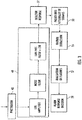
- Figure 1 schematically illustrates an aspirating detector system 20 ("system 20"). While known aspirating detectors can identify the presence of smoke, the system 20 can provide detection of a variety of chemicals and particles, with enhanced sensitivity, in a compact structure.
- the system 20 generally includes a detection unit 22 and an analyte collection network 24.
- the analyte collection network 24 is in fluid communication with a region 26 that is to be monitored for one or more target substances.
- the region 26 may be a room and the analyte may be air drawn from the room into the detector unit 22 for analysis.
- the detection unit 22 may be used to determine the presence of smoke or chemicals in the analyte (and thus in the region 26), as well as identify the type of chemical(s) in the analyte. Such information may then be used to identify threat situations and, if appropriate, trigger an alarm or other response.
- the detection unit 22 includes a detector 28, a fluid mover 30, such as a fan, blower, or compressor, and a controller 32.
- the controller 32 is electrically connected for communication with the detector 28 and the fluid mover 30, to control operation and receive feedback.
- Enhancing the detection capability of the detection unit 22 may include modification of detector 28, controller 32 or fluid mover 30.
- modifications to one of the three detection unit elements may be completed to enhance the operation.
- modifications to all three elements in parallel may result in a further increase in performance. This can be attributed to the optimization of the three elements communicating fluidly or electrically in the detection unit.
- electrical connections or communications herein can refer to wire connections, wireless connections, optical connections, or combinations of wired and wireless connections.
- the detection unit 22 is fluidly connected with the analyte collection network 24.
- the fluid mover 30 serves to draw analyte (e.g., air) from the region 26 into the analyte collection network 24.
- the analyte collection network 24 may include one or more conduits 24a (e.g., pipes) and multiple ports 24b. By operation of the fluid mover 30, the analyte is drawn through the ports 24b and into the conduits 24a.
- the analyte collection network 24 delivers the analyte to the detector unit 22 for analysis in the detector 28. Delivery of, and circulation through, the detector 28 is continuous.
- the system 20 can be turned ON or OFF, when ON the detector 28 is continuously fed analyte and continuously analyzes the received analyte, as opposed to a "batch" process in which discrete analyte samples are sealed inside of a detector and analyzed batch-by-batch.
- FIG. 2 illustrates an example of the detector 28 of Figure 1 .
- the detector 28 includes a chamber 34 that has an inlet 36 and an outlet 38 for flow of the analyte, which is represented at F.
- the inlet 36 is fluidly connected with the analyte collection network 24, and the outlet 38 may be fluidly connected with the region 26 to exhaust analyzed analyte back into the region 26.
- the detector 28 includes a light source 40 adjacent the chamber 34.
- the light source 40 when operated, emits a light beam (represented at B) through the chamber 34 over a range of wavelengths.
- the light source 40 is electrically connected with the controller 32, as represented at 40a, such that the controller 32 may control operation of the light source 40 with regard to pulse modulation by varying light intensity (power or energy density), varying light wavelength, or varying pulse frequency.
- the light source 40 is a laser that can emit a laser beam at a wavelength that can be altered in a controlled manner across a range of wavelengths.
- the light intensity and/or pulse frequency can be varied in a controlled manner.
- the controller 32 may scan the analyte in the chamber 34 across ranges of wavelengths, intensities, and/or pulse frequencies as described further below.
- light refers to wavelengths in the visible spectrum, as well near infrared and near ultraviolet regions.
- the light source is a laser that has a laser energy density or power density of 0.01-100 mW/cm 2 .
- the detector 28 also includes a sensor 42 adjacent the chamber 34.
- the term "adjacent" refers to the sensor's 42 close proximity or adjoined with the chamber 34.
- the sensor 42 may be inside the chamber 34, outside the chamber 34, or portions of the sensor are inside the chamber 34 and other portions are outside of the chamber 34.
- the sensor 42 may be a solid state sensor, such as but not limited to, a photosensor.
- Example photosensors may include photodiodes, bipolar phototransistors, photosensitive field-effect transistors, and the like.
- the sensor 42 is offset from the direct path of the light beam B, to capture received scattered light from the analyte.
- the sensor 42 is electrically connected with the controller 32, as represented at 42a, and is operable to emit sensor signals to the controller 32 responsive to received scattered light from interaction of the light beam B with the analyte in the chamber 34.
- the sensor signals are proportional to the intensity of the received scattered light received by the sensor 42.
- the controller 32 may include hardware (e.g., one or more microprocessors and memory), software, or both, that are configured (e.g., programmed) to carry out the functionalities described herein.
- the controller 32 receives the sensor signals and is configured to analyze the sensor signals and make several determinations.
- the controller 32 determines whether a target substance is present in the analyte based on an intensity of the received scattered light and the controller 32 also determines a chemical identity of the target substance from a spectrum of the received scattered light over the range of wavelengths. These two determinations are referred to herein as, respectively, a presence determination and an identity determination.
- the controller 32 can make a presence determination by analyzing the intensity of the sensor signals. For instance, when no target substance is present, the sensor signals are low, indicating no analyte present. This can be considered to be a baseline or background signal. When a target substance is present and scatters light, the sensor signals increase in comparison to the baseline signal. Higher amounts of target substance produce more scattering and a proportional increase in the sensor signal. An increase that exceeds a predetermined threshold, which may be correlated to a certain concentration in the analyte, serves as an indication by the controller 32 that a target substance is present.
- the controller 32 can make an identity determination by analyzing the sensor signals over the range of wavelengths of the light beam. For instance, the controller 32 scans the analyte over the range of wavelengths to collect temporal spectra of intensity versus wavelength (or equivalent unit). Different target substance respond differently with regard to absorbance and scattering of different wavelengths of light. Thus, the spectra of different types of target substances (taking into account a baseline or background spectra) differ and may be used as a signature to identify the type of target substance by comparison of the spectrum with a spectra library or database, which may be in the memory of the controller 32. In this manner, the detector 28 can identify chemicals such as, but not limited to, carbonyls, silanes, cyanates, carbon monoxide, and hydrocarbons.
- chemicals such as, but not limited to, carbonyls, silanes, cyanates, carbon monoxide, and hydrocarbons.
- the controller 32 may scan the analyte in the chamber 34 across a range of intensities and/or pulse frequencies, to generate additional information about target substances that may also be used to identify the presence or type of target substance. For instance, the controller 32 may scan the analyte at a first intensity to collect information based on Rayleigh scattering and then scan at a second, different intensity to collect information based on Raman scattering.
- the first intensity and wavelength in one example could be scanning for an analyte at 660 nm and at a power density of 1 mW/cm 2 and collecting scattered light at 660 nm, which is indicative of Rayleigh scattering.
- the presence and identity determinations may be used individually or in combination to estimate a threat level and, if appropriate, trigger an alarm or other response.
- the combination of the presence and identity determinations may permit extended, intelligent capability.
- the identity determination may serve as a validation of the presence determination (or vice versa).
- the presence and identity determinations are used together to trigger an alarm or other response only when predesignated types of chemicals are detected and identified.
- the detector 28 may be programmed to respond to one or more target chemicals in the region 26, while disregarding other, non-target chemicals that may be present.
- the detector 28 may be programmed to respond to non-target chemicals in the region 26, while disregarding others, when the non-target chemicals are present at concentrations above a predefined threshold at which the non-target chemicals would be toxic. Such a capability can also be used to reduce false alarms from non-target chemicals by triggering an alarm only for target chemicals but not non-target chemicals.
- the configuration of the detector 28 facilitates good sensitivity and reliability for early warning capability.
- early warning sensitivity for smoke detection is 0.2 obs%/ft
- early warning sensitivity for a substance such as H 2 S is 2-5 ppm.
- One feature that contributes to good performance is that the chamber 34 is hemi-spherical.
- the hemi-spherical geometry serves to deflect the flow of the analyte as it enters the chamber 34.
- the flow from the inlet 36 enters the chamber 34 and deflects off of the left side or half of the chamber 34 toward the right side or half of the chamber 34. From the right side or half, the flow deflects back toward the center region of the chamber 34 and then through the outlet 38. The flow thus mixes well inside of the chamber 34 and focuses the flow and any particles to the outlet 38.
- the hemi-spherical shape may also enhance collection of the scattered light.
- the sensor 42 is located central to the curvature of the walls of the chamber 34. While a portion of the scattered light may be directly received by the sensor 42, much of the light is scattered in other directions, toward the walls of the chamber 34. This scattered light reflects off of the walls of the chamber 34, which are mirrored, and toward the sensor 42 because of the semi-spherical shape and central location of the sensor 42. Thus, not only is the exposure increased to increase light scattering, but a greater amount of the scattered light is directed to the sensor 42.
- the orientation of the light source 40 with regard to the outlet 38 also serves to enhance sensitivity.
- the light source 40 is aimed at the outlet 38 such that, when operated, the light beam B exits the chamber 34 through the outlet 38.
- the detector 28 includes a secondary chamber 44 between an outer housing 46 and the chamber 34, and a beam stop 48 disposed in the secondary chamber 44.
- the beam stop 48 diverts and/or absorbs the light beam B to reduce reflect-back into the chamber 34, which could otherwise reduce sensitivity to the received scattered light and debit the presence and identity determinations.
- the controller 32 may also be configured to determine a dynamic reference (baseline) condition of the analyte based on one or more wavelengths over the range of wavelengths, compare the sensor signals to the dynamic reference condition, and trigger an alarm in response to one or more of the sensor signals exceeding the dynamic reference condition by a threshold amount.
- a dynamic reference (baseline) condition of the analyte based on one or more wavelengths over the range of wavelengths, compare the sensor signals to the dynamic reference condition, and trigger an alarm in response to one or more of the sensor signals exceeding the dynamic reference condition by a threshold amount.
- the signal from the sensor 42 is sampled at given intervals, such as once a second.
- the sensor signal may also be processed to provide a meta-value.
- a meta-value is a value derived from the sensor 42 but may not be used directly to determine the presence of a gas or smoke.
- the signal or meta-values are then statistically analyzed.
- the distribution of readings is statistically analyzed in the controller 32.
- a mean and a standard deviation of the signal level are calculated from the distribution.
- the distribution curve is in a constant state of being updated (i.e. the dynamic reference condition), the samples reducing exponentially in significance in relation to the samples taken subsequent to them.
- Y is the new mean of the signal
- Y1 is the most recent sampled signal
- w is a weighting factor
- Y old is the current mean of the signal.
- a weighted average over a one month period w 1/2592000 1/sec if signals were collected once per second (assuming a 30-day month). The most recent readings are thus the most significant while older readings are less significant and eventually become completely insignificant.
- Y Y 1 * w + Yold * 1 ⁇ w
- Adjustments can be made to reduce the probability of false alarms without sacrificing accurate detection of target chemicals.
- the probability of a given signal level occurring may be calculated from the instant distribution, or conversely a given probability of a signal level occurring will correspond to a specific signal level.
- an alarm level can be continually re-set for a given fixed probability of occurring. In the instance of one sample being taken every second, if the level is set to correspond to 1 chance in 10 6 , then an unwanted alarm would be expected only once every 115 days on average from normal fluctuations of the signal level. If it is set at 1 in 10 7 , an unwanted alarm would be generated on average once every 3 years. The probability of this signal level occurring five times in a row will be once every 243 years.
- Such a method provides the means for setting the alarm level with a given theoretical probability of an unwanted alarm occurring. Also the mean level of signal is known from the assumed normal distribution and any fall in this below what is expected may indicate a fault in the sensor 42.
- the signal level that corresponds to the given constant probability changes dynamically. That is, rather than setting a constant signal level as an alarm threshold, which would have a variable probability as new sample signals are collected, the probability is constant and the corresponding signal level varies.
- Figure 3 shows a schematic flow diagram of signal processing for making an alarm response decision.
- An algorithm generates the meta-values executed by the controller 32, where each of the signals represents scattered light received by the sensor 42.
- the signals may be pre-processed at block 49 for amplification, noise filtering, and low pass filtering plus lossless discrete differentiation (LDD), which results in a processed signal at 51.
- the processed signal (or, if the signal is not pre-processed, raw detector data) indicative of scattered light is parsed at block 53 into a plurality of signals.
- background signals are removed from the data before the signal features are evaluated to provide meta-values.
- pulse features include, but are not limited to, a peak height, an area under a curve defined by the signal, statistical characteristics such as mean, variance, and/or higher-order moments, correlations in time, frequency, space, and/or combinations thereof, and empirical features as determined by deep learning, dictionary learning, and/or adaptive learning and the like.
- the signal of interest may be parsed and pulse features extracted from the raw signal being collected by the sensor 42.
- the set of raw data for the algorithm analysis may cover a period of time.
- a period of recorded light intensity may cover 1e-9 seconds to 1e3 seconds, 1e-6 seconds to le3 seconds, or 1e-3 seconds to 1e3 seconds.
- the features extracted from the signal may include, but are not limited to, height, full width at half maximum, signal pick-up time, signal drop-off time, group velocity, integration, rate of change, mean, and variance, for example.
- the alarm is generated based on the input value.
- the alarm response decision looks for a matching relationship between the features, evaluation, and a value in order to determine the presence of smoke or gas.
- the alarm response decision is based on a Boolean operator that would produce a true or false output. A true output would indicate the presence of smoke or gas.
- the relationship may be defined as when the pulse height feature exceeds a threshold value. In this case, the relationship is true when the sensor 42 records an intensity larger than a threshold and an alarm is then triggered at block 59.
- the feature evaluation in block 57 may also employ classifiers including those that may be learned from the signal via deep learning techniques including, but not limited to deep neural networks, convolutional neural networks, recursive neural networks, dictionary learning, bag of visual/depth word techniques, Support Vector Machine (SVM), Decision Trees, Decision Forests, Fuzzy Logic, and the like.
- the classifiers may also be constructed using Markov Model techniques, Hidden Markov Models (HMM), Markov Decision Processes (MDP), Partially Observable MDPs, Markov Decision Logic, Probabilistic Programming, and the like. The resulting meta-values from the classifiers is then analyzed statistically.
- the relationship between the light scattering and the magnitude or presence of a condition is inferred by measuring a signal's causality and dependency.
- the measure of a causality utilizes one or more signal features as an input and determines one or more outputs from a calculation of a hypothesis testing method, foreground ratio, second derivative, mean or Granger Causality Test in order to identify the relationship between the light scattering signals collected by sensor 42 and the presence of the smoke or gas from nuisances.
- one or more signal features may be used as an input to evaluate the dependency of a signal, which would enable determination of smoke or gas from nuisances.
- One or more outputs are selected from a calculation of a correlation, fast Fourier transform coefficients, a second derivative, or a window.
- the magnitude and presence of a condition may be calculated utilizing one or more evaluation approaches: a threshold, velocity, rate of change or a classifier.
- the detection algorithm may include utilizing the output from the calculation causality, dependency or both as meta-values. This is used to indicate the presence of the condition at one or more nodes and initiate a response.
- the controller 32 is configured via communication with the light source 40 to switch the light beam between first and second modes of operation. For instance, the light beam is switched between a detection mode of operation and an analytic mode of operation.
- the detection mode may be used when there is no target substance detected in the analyte, and the analytic mode may be used when the presence of a target substance has identified.
- the controller 32 can switch between the modes in response to identifying the presence of a target or non-target substance with regard to a predetermined threshold or, conversely, when a target or non-target substance is no longer present. In one variation, the controller 32 switches between the modes in response to a predetermined threshold concentration of a target substance.
- the alarm threshold is set to reduce or minimize false alarms.
- the light beam is operated to increase or maximize information from the analyte.
- switches between these modes may include, but are not limited to, changing beam intensity, changing beam pulse frequency, changing beam wavelength or wavelength range, or changing combinations of intensity, frequency, and wavelength.
- the intensity, pulse frequency, wavelength, wavelength range, or combinations of these may be adjusted to switch from a setting that is targeted to minimize false alarms to a setting that is targeted to maximize information from the analyte.
- the intensity, pulse frequency, wavelength, wavelength range, or combinations of these may be adjusted to switch from the setting that is targeted to maximize information from the analyte to the setting that is targeted to minimize false alarms.
- Figures 4A and 4B illustrate variations of the detector 28.
- the sensor 42 is centered above the chamber 34, which is shown as position X.
- the sensor 42 may alternatively be located at other positions adjacent the chamber 34; as will be described below, different sensor positions may be used to distinguish different conditions such as may be caused by hazards or mere nuisances.
- the sensor 42 may be located at any of alternate positions T, V, W, Y, and Z (multiple sensors at these positions may be referred to herein as sensors 42).
- the positions X, T, V, W, Y, and Z even if there is no detector, may be used to describe the spatial locations.
- W, Y, and Z fall on a plane created by the laser beam B between laser 40 and beam stop 48 and position X.
- Position W is approximately 180 degrees from position X.
- a line from position Z to position X is approximately 45 degrees to a line between position W and X.
- a line from position Y to position X is approximately 30 degrees to a line between position W and X.
- Positions V and T are out of the plane of positions W, Y, Z and X.
- a line from position T to position X is approximately 45 degrees to a line between position W and X.
- a line from position V to position X is approximately 30 degrees to a line between position W and X.
- the plane created by W, V, T and X is orthogonal to the plane of positions W, Y, Z and X.
- the detector 28 includes multiple sensors 42 located at any of positions X, T, V, W, Y, and Z.
- the detector includes 2, 3, 4, 5, or 6 sensors 42 arranged among positions X, T, V, W, Y, and Z.
- the sensors 42 record the scattered light from the analyte at an angle with respect to the light source 40.
- the angular-and dependent scattering is related to the size, shape, and refractive index of the particulates in the analyte inside the chamber 34.
- the scattered light collected by sensors 42 may then be used to distinguish smoke particulates related to a fire from dust and water vapor that is associated with nuisances from the environment, all of which can cause different, unique responses across the sensors 42.
- one of the positions X, T, V, W, Y, or Z may be in a back-scattering position and another of the positions X, T, V, W, Y, or Z may be in a forward-scattering position.
- the light intensity as a function of obscuration at these two positions is different and may then be used to compute different features that are used in an algorithm to distinguish smoke particles from dust and moisture.
- Figure 5 illustrates another example detector 128.
- like reference numerals designate like elements where appropriate and reference numerals with the addition of one-hundred or multiples thereof designate modified elements that are understood to incorporate the same features and benefits of the corresponding elements.
- the detector 128 of Figure 5 includes the same features / benefits of the detector 28 from above.
- the sensor 142 is adjacent but outside of the chamber 34, in the secondary chamber 44.
- the sensor 142 is aligned with the light source 40 (i.e., the path of the light beam B) and outlet 38 such that the light beam B directly impinges on the sensor 142.
- the sensor 142 is operable to emit sensor signals to the controller 32 responsive to received light and the sensor signals are proportional to the intensity of the received light.
- the sensor 142 is aligned with the light source 40 rather than offset (as the sensor 42)
- the light that is received by the sensor 142 is light that is transmitted through the analyte. Light that is absorbed and/or scattered by a target substance in the analyte may not be received by the sensor 142.
- the sensor signals represented the intensity of received scattered light.
- the sensor signals in the detector 128 represent received transmitted light.
- the controller 32 uses this received transmitted light in a similar manner as the received scattered light signals to make a presence determination.
- the sensor signals decrease in comparison to the baseline signal. Higher amounts of target substance produce more absorbance and scattering and a proportional decrease in the sensor signals. A decrease that exceeds a predetermined threshold may serve as an indication by the controller 32 that the target substance is present.
- the sensor 142 may be used to make identity determinations by analyzing the sensor signals over the range of wavelengths of the light beam to collect temporal spectra of intensity versus wavelength (or equivalent unit).
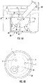
- Figure 6 illustrates another example of a detector unit 122 that may be used in the system 20.
- like reference numerals designate like elements where appropriate and reference numerals with the addition of one-hundred or multiples thereof designate modified elements that are understood to incorporate the same features and benefits of the corresponding elements.
- the detector unit 122 of Figure 6 includes the same features / benefits of detector unit 22 of Figure 1
- the detector 28 of Figure 6 includes the same features / benefits of the detector 28 / 128 from above.
- the detector unit 122 includes a passage 50 that has an inlet 50a and an outlet 50b for flow of an analyte, which again is represented at F.
- the passage 50 splits into first and second legs 50c/50d.
- the first leg 50c is a bypass leg and the second leg 50d is an analysis leg.
- a speed-oscillating fluid mover 130 is disposed in the passage 50.
- the fluid mover 130 is electrically connected with a controller 132, which can control operation of the fluid mover 130 and receive feedback.
- the controller 132 may be used in addition to the controller 32 associated with the detector 28 and described above. Alternatively, the described functionalities of the controllers 32/132 may be combined into a single controller.
- the fluid mover 130 may be a fan, blower, or compressor that is capable of being operated at multiple controlled speeds and may continuously oscillate. An average flow is known or may be determined by an installer and used to adjust an average and "worst case" transit time from the fluid mover 130 or other inlet reference position to the detector 28 (which may include any of the features of the detector 128 of Figure 5 ). This may then be used to plan the installation pipe layout of the passage 50.
- a flow sensor 54 is also disposed in the second leg 50d of the passage 50, downstream of the filter 52.
- the flow sensor 54 is electrically connected to the controller 132 and operable to emit flow sensor signals thereto.
- the detector 28 (or alternatively 128) may be located downstream of the flow sensor 54.
- the fluid mover 130 operates to draw analyte into the analyte collection network 24 and, in turn, the detector unit 122.
- the analyte may contain debris, large particles, or other pollutants that are undesired in the detector 28.
- the filter 52 serves to remove pollutants from the incoming flow of analyte to produce a cleaner or "clean" stream of flow of the analyte downstream of the filter 52.
- accumulation of pollutants in the filter 52 could reduce analyte flow to the detector 28, thus debiting detector performance.
- the speed-oscillating fluid mover 130, flow sensor 54, and controller 132 facilitate identification of such obstructions, which may be used to enhance system performance.
- the controller 132 is configured to determine whether the filter 52 becomes obstructed based on a response by the flow sensor 54 to speed-oscillations of the speed-oscillating fluid mover 130.
- the controller 132 oscillates the speed of the fluid mover 130 (i.e., between two speed set-points) via an oscillation generator circuit 130a, which may be in the fluid mover 130, outside the fluid mover 130, or in the controller 132.
- an oscillation generator circuit 130a which may be in the fluid mover 130, outside the fluid mover 130, or in the controller 132.
- the filter 52 is unobstructed
- changes in the speed of the fluid mover 130 between two different set point speeds generate two corresponding flows of the clean stream by the flow sensor 54.
- the difference between these two flows of the clean stream at the two different speeds represents an unobstructed condition and may be used to identify an obstructed condition. For instance, when the filter 52 becomes obstructed, the difference between the two flows by the flow sensor 54 changes.
- the controller 132 decides that an obstruction condition exists if this change in the difference between the two flows exceeds a threshold. In response, the controller 132 may trigger a fault, indicate that the operation of the detector 28 may have reduced reliability, and/or cease operation of the detector 28.
- the controller 132 oscillates the speed of the fluid mover between Speed 1 and Speed 2, which differs from Speed 1 by plus or minus 1-500%, or in more limiting examples from 1-30%.
- Speed 1 the flow at the flow sensor 54 is 5.5 meters per second (m/s) and at Speed 2 the flow at the flow sensor 54 is 9.5 m/s. The difference between the flows is thus 4.0 m/s.
- the flows at the two speeds are constant and the difference between the flows is thus also constant.
- the filter 54 then takes on particles or debris from the analyte such that flow of the analyte through the filter 54 is partially blocked.
- the flow at the flow sensor 54 is 2.0 m/s and the flow at Speed 2 is 3.5 m/s, for a difference in flow of 1.5 m/s.
- the controller 132 has a preset threshold change of 1.0 m/s, meaning that a change of 1.0 m/s or more in the 4.0 m/s value from the unobstructed state indicates an obstruction.
- the change in the difference value from 4.0 m/s to 1.5 m/s is 2.5 m/s, which is greater than the 1.0 m/s threshold.
- the controller 132 identifies that that an obstruction condition exists and triggers an alarm or other response.
- the flow sensor 54 includes a constant-power heating element, such as a resistor powered at constant current, and a thermometer (or other temperature sensor) attached to the heating element. Changes in the flow of analyte over the heating element change the rate of heat exchange of the heating element, thereby altering the temperature at the thermometer. While the filter 52 is unobstructed, the speed changes of the fluid mover 130 will thus change the temperature. When the filter is obstructed, the temperature will not change or will change less, thereby indicating existence of an obstruction in relation to a preset threshold.
- a constant-power heating element such as a resistor powered at constant current
- a thermometer or other temperature sensor
- the controller 132 could also be connected with an additional thermometer or other temperature sensor 60 to provide enhanced control capability.
- the temperature from temperature sensor 60 may be used as a baseline to compensate for temperature variations of the analyte that are unrelated to flow of the analyte by the flow sensor 54.
- the controller 132 may also use the speed-oscillating fluid mover 130 to enhance performance of the detector 28 (or alternatively detector 128 may be used here).
- the speed oscillations may be modulated with respect to a target average flow speed at the flow sensor 54, and thus an average flow speed into the detector 28.
- the magnitude of the speed oscillations i.e. a speed increase or a speed decrease relative to a reference speed
- the average flow speed at the flow sensor 54 is maintained at a target average flow speed or within a target range for the average flow speed. Maintaining the average flow speed constant at a target average flow speed or within a target range in turn may enhance detector reliability and sensitivity.
- Maintaining a certain flow value average also ensures that transportation time of the fluid from the sampling point to the detector has a certain average value, which is a determinant characteristic of a detection installation, because fire or target substance detection is always lagged by the transportation time from intake at a node 24b through conduits 24a to scanning at detector 28.
- the period of the oscillations may vary from 1 second to 240 seconds, and in more limiting cases from 6-12 seconds.
- the controller 132 may also be configured to determine a dynamic reference (baseline) condition of the analyte based on one or more wavelengths over the range of wavelengths, compare the sensor signals to the dynamic reference condition, and trigger an alarm in response to one or more of the sensor signals exceeding the dynamic reference condition by a threshold amount.
- the signal from the detector 28 is sampled at given intervals, such as greater than 5 samples per oscillation of the fan speed.
- the sensor signal may also be processed to provide a meta-value.
- the signal or meta-values are then statistically analyzed.
- the distribution of readings at given points in the fan speed are statistically analyzed in the controller 132.
- a mean and a standard deviation of the signal level are calculated from the distribution.
- the distribution curve is in a constant state of being updated. This constant value for the concentration is then obtained by filtering the data.
- a filter could be averaging as an example.
- the raw sensor signals are also analyzed to relate light scattering in the detector 28 as a function of the oscillating flow rate to enhance detectability needed to achieve high sensitivity particle or gas detection. This may be achieved by performing temporal analysis to evaluate frequency dependent sensor signals to the period in the air speed oscillation.
- the detection algorithm may be configured to apply one or more of a Fourier transform, Wavelet transform, space-time transform, Choi-Williams distribution, Wigner-Ville distribution and the like, to the signals to convert the signals from a temporal domain to a frequency domain. This transformation may be applied to the signals when the sensors 42 are being analyzed individually, collectively during a data fusion, or both.
- One example approach for establishing control parameters to enhance operation of the fluid mover 130, controller 132, and detector 28 uses linear optimization.
- An example linear optimization approach is shown in the flow diagram in Figure 7 and starts at block 61 with defining a set of reference environmental conditions under which to test the response of the detector 28, as further explained below. This is followed in block 63 by operating the detector 28 in a reference environment and varying control parameters of the fluid mover 130, controller 132, and detector 28.
- Performance metrics are then calculated at block 65 by comparing output of alarm response decisions to known representative environments.
- Detector unit parameters are then selected at block 67 based on the performance metric closest to the performance goal.
- the reference set of environmental tests is intended to represent the conditions in which the detector 28 (or 128) operates in its end use environment.
- the reference set of environmental tests may be in a lab or based on data collected during the operation of the detector 28 in its end use environment.
- the lab tests are prescriptive reference tests.
- the detector 28 is already in the field and the reference tests are performance-based environmental tests that have data categorized into background, nuisances, smoke or gas as further described below with reference to Fig. 8 .
- This categorization sets the ground truth.
- the detector response is then compared to the ground truth to determine performance.
- the resulting performance for a set of parameters may be evaluated.
- the optimization method may thus be run before installation or after installation in a building, data center, or industrial complex.
- the reference test has background, undesirable regions of alarm, and desirable regions of alarm, each labeled with the time period in hours ("HR") over which it occurs.
- the frequency spacing and timing, number and order may be changed or adjusted.
- the background is the normal environment that the detection unit is placed.
- the undesirable regions of alarm are those areas where nuisances such as dust or water vapor maybe present.
- the desirable alarm regions are when a fire or gas of interest is present and therefore an alarm is desirable.
- the reference set of environmental tests may be an experimental test, such as exposure to given levels of smoke over a period of time.
- the operation is based on a simulated algorithm response decision or field collected data.
- the same sensor 42 responses are run to determine how changes in the controller 132 would impact the alarm response decision.
- Figure 9 illustrates example graphs in which data as a percent transmission was recorded at 1 second intervals.
- the intensity of the sensor 42 signal features are represented by lines 71.
- the alarm response decision value is shown by lines 73. When line 71 is greater than line 73 at a given time, the alarm response decision relationship is true and an alarm is triggered.
- the graphs demonstrate that two signal feature evaluations may have different algorithm response decisions.
- the algorithm response decision line 73 is constant, and thus a large portion of the line 71, including a plateau portion 71a, is above the line 73.
- the algorithm response decision line 73 varies through the reference test, and only peaks 71b are above the line 73 while the plateau portion 71a is below line 73.
- the performance metric may be calculated from comparing output of the alarm response decision to known representative environments.
- the performance metric is the number of correctly identified values or the true positive rate (TPR) based on the alarm response decision relationship line 73 compared to the number of incorrectly identified values called the false positive rate (FPR) outputted based on the alarm response decision relationship line 73.
- TPR and FPR ranges from 0 to 1; and a pair of TPR and FPR values are calculated for each parameter as described below. As a number of parameters are tabulated, the values may be plotted. An example of such a plot is shown in Figure 10 , in which the resulting TPR and FPR of the first signal feature at line 75 and the second signal features at line 77 are plotted across several parameter variations.
- the parameters may be changes to the sensor 42 (e.g., number, response, type, filter wavelength, or orientation), light source (e.g., wavelength, light intensity, or pulse frequency), controller (e.g., feature, feature evaluation, algorithm, or relationship), fluid mover (e.g., fan speed, oscillation period, and magnitude).
- the TPR and FPR values are related to a set of detector unit parameters.
- a combination of parameters may then be selected for a performance metric closest to a desired performance goal by selection of the parameters based on the resulting TPR, FPR, or both.
- weights are applied to either values or both values.
- the maximum TPR value that has the minimum FPR value is considered optimum.
- the performance goal in some examples may have a TPR equal to 1 and a FPR value equal to 0.
- the FPR value is increased slightly to select parameters with a higher TPR value. This may be achieved by graphically calculating the linear distance of a TPR and FPR pair to a given goal and comparing all tabulated linear distances to determine the minimum linear distance.
- the identified TPR and FPR pair that has the minimum linear distance provides an optimized detector operation with respect to the reference test.
- the optimization technique reduces variability by balancing hardware performance with the detection algorithms that cannot be achieved by aspirating systems that rely on fixed sensitivity.
Landscapes
- Physics & Mathematics (AREA)
- Analytical Chemistry (AREA)
- General Physics & Mathematics (AREA)
- Chemical & Material Sciences (AREA)
- General Health & Medical Sciences (AREA)
- Biochemistry (AREA)
- Life Sciences & Earth Sciences (AREA)
- Health & Medical Sciences (AREA)
- Immunology (AREA)
- Pathology (AREA)
- Spectroscopy & Molecular Physics (AREA)
- Business, Economics & Management (AREA)
- Emergency Management (AREA)
- Investigating Or Analysing Materials By Optical Means (AREA)
- Investigating Or Analysing Materials By The Use Of Chemical Reactions (AREA)
Priority Applications (1)
| Application Number | Priority Date | Filing Date | Title |
|---|---|---|---|
| EP22163939.6A EP4053542B1 (de) | 2018-03-13 | 2019-03-13 | Ansaugendes detektorsystem |
Applications Claiming Priority (1)
| Application Number | Priority Date | Filing Date | Title |
|---|---|---|---|
| US201862642194P | 2018-03-13 | 2018-03-13 |
Related Child Applications (2)
| Application Number | Title | Priority Date | Filing Date |
|---|---|---|---|
| EP22163939.6A Division-Into EP4053542B1 (de) | 2018-03-13 | 2019-03-13 | Ansaugendes detektorsystem |
| EP22163939.6A Division EP4053542B1 (de) | 2018-03-13 | 2019-03-13 | Ansaugendes detektorsystem |
Publications (3)
| Publication Number | Publication Date |
|---|---|
| EP3540705A2 true EP3540705A2 (de) | 2019-09-18 |
| EP3540705A3 EP3540705A3 (de) | 2019-10-09 |
| EP3540705B1 EP3540705B1 (de) | 2022-05-04 |
Family
ID=65812099
Family Applications (2)
| Application Number | Title | Priority Date | Filing Date |
|---|---|---|---|
| EP22163939.6A Active EP4053542B1 (de) | 2018-03-13 | 2019-03-13 | Ansaugendes detektorsystem |
| EP19162661.3A Active EP3540705B1 (de) | 2018-03-13 | 2019-03-13 | Ansaugendes detektorsystem |
Family Applications Before (1)
| Application Number | Title | Priority Date | Filing Date |
|---|---|---|---|
| EP22163939.6A Active EP4053542B1 (de) | 2018-03-13 | 2019-03-13 | Ansaugendes detektorsystem |
Country Status (3)
| Country | Link |
|---|---|
| US (1) | US11783688B2 (de) |
| EP (2) | EP4053542B1 (de) |
| ES (1) | ES2978776T3 (de) |
Cited By (3)
| Publication number | Priority date | Publication date | Assignee | Title |
|---|---|---|---|---|
| CN110517438A (zh) * | 2019-10-11 | 2019-11-29 | 四川长虹电器股份有限公司 | 一种自适应调整烟雾报警器阈值的方法及报警装置 |
| CN112907885A (zh) * | 2021-01-12 | 2021-06-04 | 中国计量大学 | 基于scnn的分散集中式家居图像火灾报警系统及方法 |
| CN118858203A (zh) * | 2024-06-28 | 2024-10-29 | 江苏久创电气科技有限公司 | 一种基于大数据的多通道红外气体检测系统及方法 |
Families Citing this family (7)
| Publication number | Priority date | Publication date | Assignee | Title |
|---|---|---|---|---|
| US11783688B2 (en) * | 2018-03-13 | 2023-10-10 | Carrier Corporation | Aspirating detector system |
| KR102904321B1 (ko) * | 2019-10-25 | 2025-12-26 | 한국전자통신연구원 | 광스펙트럼 분석을 이용한 화재감지 장치 및 방법 |
| EP3828529B1 (de) | 2019-11-27 | 2025-12-24 | Carrier Corporation | Rauchdetektor für ansaugrauchmeldersystem |
| EP4068234B1 (de) * | 2021-03-31 | 2024-11-13 | Carrier Fire & Security EMEA BV | Ansaugsystem zur erkennung von krankheitserregern |
| CN113487826A (zh) * | 2021-07-14 | 2021-10-08 | 上海鸿真电子有限公司 | 一种吸气式感烟火灾探测装置及方法 |
| US11790765B1 (en) * | 2022-08-01 | 2023-10-17 | Honeywell International Inc. | Smoke detector device with secondary detection chamber and filter |
| CN120808522B (zh) * | 2025-09-15 | 2025-12-23 | 中科(湖南)先进轨道交通研究院有限公司 | 一种基于多光谱检测的极早期火灾隐患预警系统 |
Family Cites Families (34)
| Publication number | Priority date | Publication date | Assignee | Title |
|---|---|---|---|---|
| US5123731A (en) * | 1988-02-01 | 1992-06-23 | Canon Kabushiki Kaisha | Particle measuring device |
| GB9014015D0 (en) | 1990-06-23 | 1990-08-15 | Dennis Peter N J | Improvements in or relating to smoke detectors |
| GB9315779D0 (en) | 1993-07-30 | 1993-09-15 | Stoneplan Limited | Apparatus and methods |
| CA2291203A1 (en) | 1998-12-04 | 2000-06-04 | George A. Schoenfelder | Aspirated detector with flow sensor |
| US6476352B2 (en) * | 2000-12-18 | 2002-11-05 | General Electric Company | Laser beam stop sensor and method for automatically detecting the presence of laser beam stop material using a laser beam stop sensor |
| DE10124280A1 (de) | 2001-05-23 | 2002-12-12 | Preussag Ag Minimax | Selbstansaugende Brandmeldeeinrichtung |
| GB2389176C (en) | 2002-05-27 | 2011-07-27 | Kidde Ip Holdings Ltd | Smoke detector |
| US7106442B2 (en) * | 2003-04-29 | 2006-09-12 | Silcott David B | Multi-spectral optical method and system for detecting and classifying biological and non-biological particles |
| DE102004004098B3 (de) * | 2004-01-27 | 2005-09-01 | Wagner Alarm- Und Sicherungssysteme Gmbh | Verfahren zur Auswertung eines Streulichtsignals und Streulichtdetektor zur Durchführung des Verfahrens |
| WO2006050569A1 (en) | 2004-11-12 | 2006-05-18 | Vfs Technologies Limited | Method and apparatus for determining flow |
| US7669457B2 (en) | 2007-07-24 | 2010-03-02 | Honeywell International Inc. | Apparatus and method of smoke detection |
| US8098166B2 (en) * | 2009-04-23 | 2012-01-17 | Honeywell International Inc. | Variable air speed aspirating smoke detector |
| US9269248B2 (en) | 2009-09-03 | 2016-02-23 | Life Safety Distribution Ag | Environmental parameter responsive, aspirated fire detector |
| AU2011223512B2 (en) | 2010-03-05 | 2016-07-21 | Garrett Thermal Systems Limited | Filter bypass |
| US9993828B2 (en) | 2010-03-05 | 2018-06-12 | Garrett Thermal Systems Limited | Particle precipitator |
| EP2407946B1 (de) | 2010-07-15 | 2012-09-05 | Siemens Schweiz AG | Erkennen von Verstopfungen und Unterbrüchen bei einem Ansaug-rauchmelder (ASD) |
| DE102010042700B4 (de) | 2010-10-20 | 2013-12-24 | Siemens Aktiengesellschaft | Detektion und Ortsbestimmung eines Brandes mit einem Doppelrohr-Ansaugrauchmelder mit gemeinsamer Detektoreinheit |
| DK2492882T3 (da) | 2011-02-28 | 2014-05-12 | Hager Controls | Anordning til detektering af forhindringer, der tildækker en røgdetektor |
| EP2926325A4 (de) | 2012-11-27 | 2017-01-11 | Xtralis Technologies Ltd | Branderkennung |
| EP2650852A1 (de) | 2012-12-10 | 2013-10-16 | Siemens Aktiengesellschaft | Optische Empfangseinheit, insbesondere für einen nach dem Streulichtprinzip arbeitenden optischen Rauchmelder |
| US9075007B2 (en) | 2012-12-12 | 2015-07-07 | American Mine Research, Inc. | Active sampling smoke sensor for the mining industry |
| CN203025892U (zh) | 2013-01-08 | 2013-06-26 | 中国科学技术大学 | 一种主动吸气式点型光电感烟探测器 |
| US9140648B2 (en) * | 2013-03-12 | 2015-09-22 | Ecolab Usa Inc. | Fluorometer with multiple detection channels |
| GB2513854A (en) | 2013-05-04 | 2014-11-12 | Protec Fire Detection Plc | Improvements in and relating to aspirating smoke detectors |
| EP2848913A1 (de) | 2013-09-12 | 2015-03-18 | Siemens Schweiz AG | Detektionsgerät zur Feinstaubbestimmung |
| EP2879104B2 (de) | 2013-11-27 | 2022-05-11 | Siemens Schweiz AG | Zusatzeinrichtung für einen als Punktmelder ausgebildeten Gefahrenmelder zur Funktionsüberwachung des Gefahrenmelders, sowie Anordnung und Verwendung einer solchen Einrichtung |
| CN203759818U (zh) | 2013-12-20 | 2014-08-06 | 中国科学技术大学 | 一种基于复合探测技术的吸气式飞机货舱火灾探测装置 |
| CN104200606B (zh) | 2014-07-18 | 2017-02-15 | 中国科学技术大学 | 一种无光学迷宫的点型光散射式感烟探测器及信号处理方法 |
| CN104574776A (zh) | 2015-01-20 | 2015-04-29 | 西安博康电子有限公司 | 一种点型主动感烟探测器 |
| JP6688966B2 (ja) * | 2015-07-27 | 2020-04-28 | パナソニックIpマネジメント株式会社 | 粒子検出センサ |
| US10078948B2 (en) | 2016-01-26 | 2018-09-18 | Honeywell International Inc. | Smoke detector with a double optical chamber |
| US11127270B2 (en) | 2016-11-11 | 2021-09-21 | Carrier Corporation | High sensitivity fiber optic based detection |
| KR102182575B1 (ko) * | 2017-10-23 | 2020-11-26 | 더 유나이티드 스테이츠 오브 어메리카, 애즈 리프리젠티드 바이 더 세크러테리, 디파트먼트 오브 헬쓰 앤드 휴먼 서비씨즈 | 스펙트럼 산란 유세포 분석을 위한 광학적 구성 방법 |
| US11783688B2 (en) * | 2018-03-13 | 2023-10-10 | Carrier Corporation | Aspirating detector system |
-
2019
- 2019-03-12 US US16/299,461 patent/US11783688B2/en active Active
- 2019-03-13 ES ES22163939T patent/ES2978776T3/es active Active
- 2019-03-13 EP EP22163939.6A patent/EP4053542B1/de active Active
- 2019-03-13 EP EP19162661.3A patent/EP3540705B1/de active Active
Non-Patent Citations (1)
| Title |
|---|
| None |
Cited By (3)
| Publication number | Priority date | Publication date | Assignee | Title |
|---|---|---|---|---|
| CN110517438A (zh) * | 2019-10-11 | 2019-11-29 | 四川长虹电器股份有限公司 | 一种自适应调整烟雾报警器阈值的方法及报警装置 |
| CN112907885A (zh) * | 2021-01-12 | 2021-06-04 | 中国计量大学 | 基于scnn的分散集中式家居图像火灾报警系统及方法 |
| CN118858203A (zh) * | 2024-06-28 | 2024-10-29 | 江苏久创电气科技有限公司 | 一种基于大数据的多通道红外气体检测系统及方法 |
Also Published As
| Publication number | Publication date |
|---|---|
| EP3540705B1 (de) | 2022-05-04 |
| EP4053542A2 (de) | 2022-09-07 |
| EP4053542A3 (de) | 2022-11-16 |
| US11783688B2 (en) | 2023-10-10 |
| US20190287364A1 (en) | 2019-09-19 |
| EP3540705A3 (de) | 2019-10-09 |
| ES2978776T3 (es) | 2024-09-19 |
| EP4053542B1 (de) | 2024-05-01 |
Similar Documents
| Publication | Publication Date | Title |
|---|---|---|
| EP3540705B1 (de) | Ansaugendes detektorsystem | |
| EP1889238B1 (de) | Brand- oder rauchmelder mit hochleistungs-fehlalarmunterdrückung | |
| KR100955994B1 (ko) | 산란광 신호를 측정하기 위한 방법 및 상기 방법을구현하는 산란광 검출기 | |
| JP3973762B2 (ja) | 警報システム | |
| US20180136053A1 (en) | Fiber optic based smoke and/or overheat detection and monitoring for aircraft | |
| US20220157408A1 (en) | Pollution type sensing | |
| EP4300457A2 (de) | Hochempfindliche glasfaserbasierte detektion | |
| CN108074369A (zh) | 针对飞行器的基于光纤的烟雾和/或过热检测和监测 | |
| AU2010202665B2 (en) | Circuitry to monitor and control source of radiant energy in smoke detector | |
| CN119888949A (zh) | 一种基于量子光探测的烟雾报警方法及系统 | |
| US11598722B2 (en) | Multi-point detection system | |
| EP3821415B1 (de) | Erhöhte robustheit für hochempfindliche faseroptische rauchdetektion | |
| CN110632014A (zh) | 厨房设备及其控制方法、计算机可读存储介质 | |
| EP3538872B1 (de) | Verfahren zur faseroptik-basierten messung eines zustands | |
| FI111666B (fi) | Palohälytysjärjestelmä tulipalojen varhaiseksi toteamiseksi | |
| EP3539107B1 (de) | Auf hochempfindlicher faseroptik basierende detektion | |
| JP7414372B2 (ja) | 携帯型補助検出システム | |
| CN120526526B (zh) | 异物清除方法、装置、电子设备及存储介质 | |
| US20190287370A1 (en) | High sensitivity fiber optic based detection | |
| EP4160563A1 (de) | Brandunterscheidung durch zeitliche musteranalyse |
Legal Events
| Date | Code | Title | Description |
|---|---|---|---|
| PUAI | Public reference made under article 153(3) epc to a published international application that has entered the european phase |
Free format text: ORIGINAL CODE: 0009012 |
|
| STAA | Information on the status of an ep patent application or granted ep patent |
Free format text: STATUS: THE APPLICATION HAS BEEN PUBLISHED |
|
| PUAL | Search report despatched |
Free format text: ORIGINAL CODE: 0009013 |
|
| AK | Designated contracting states |
Kind code of ref document: A2 Designated state(s): AL AT BE BG CH CY CZ DE DK EE ES FI FR GB GR HR HU IE IS IT LI LT LU LV MC MK MT NL NO PL PT RO RS SE SI SK SM TR |
|
| AX | Request for extension of the european patent |
Extension state: BA ME |
|
| AK | Designated contracting states |
Kind code of ref document: A3 Designated state(s): AL AT BE BG CH CY CZ DE DK EE ES FI FR GB GR HR HU IE IS IT LI LT LU LV MC MK MT NL NO PL PT RO RS SE SI SK SM TR |
|
| AX | Request for extension of the european patent |
Extension state: BA ME |
|
| RIC1 | Information provided on ipc code assigned before grant |
Ipc: G01N 21/53 20060101ALN20190904BHEP Ipc: G08B 17/103 20060101AFI20190904BHEP |
|
| STAA | Information on the status of an ep patent application or granted ep patent |
Free format text: STATUS: REQUEST FOR EXAMINATION WAS MADE |
|
| 17P | Request for examination filed |
Effective date: 20200330 |
|
| RBV | Designated contracting states (corrected) |
Designated state(s): AL AT BE BG CH CY CZ DE DK EE ES FI FR GB GR HR HU IE IS IT LI LT LU LV MC MK MT NL NO PL PT RO RS SE SI SK SM TR |
|
| RIC1 | Information provided on ipc code assigned before grant |
Ipc: G08B 17/103 20060101AFI20200914BHEP Ipc: G01N 21/53 20060101ALN20200914BHEP |
|
| GRAP | Despatch of communication of intention to grant a patent |
Free format text: ORIGINAL CODE: EPIDOSNIGR1 |
|
| STAA | Information on the status of an ep patent application or granted ep patent |
Free format text: STATUS: GRANT OF PATENT IS INTENDED |
|
| RIC1 | Information provided on ipc code assigned before grant |
Ipc: G01N 21/53 20060101ALN20200918BHEP Ipc: G08B 17/103 20060101AFI20200918BHEP |
|
| RIC1 | Information provided on ipc code assigned before grant |
Ipc: G08B 17/103 20060101AFI20201007BHEP Ipc: G01N 21/53 20060101ALN20201007BHEP |
|
| INTG | Intention to grant announced |
Effective date: 20201023 |
|
| GRAJ | Information related to disapproval of communication of intention to grant by the applicant or resumption of examination proceedings by the epo deleted |
Free format text: ORIGINAL CODE: EPIDOSDIGR1 |
|
| STAA | Information on the status of an ep patent application or granted ep patent |
Free format text: STATUS: REQUEST FOR EXAMINATION WAS MADE |
|
| INTC | Intention to grant announced (deleted) | ||
| GRAP | Despatch of communication of intention to grant a patent |
Free format text: ORIGINAL CODE: EPIDOSNIGR1 |
|
| STAA | Information on the status of an ep patent application or granted ep patent |
Free format text: STATUS: GRANT OF PATENT IS INTENDED |
|
| RIC1 | Information provided on ipc code assigned before grant |
Ipc: G01N 21/53 20060101ALN20211119BHEP Ipc: G08B 17/103 20060101AFI20211119BHEP |
|
| INTG | Intention to grant announced |
Effective date: 20211222 |
|
| GRAS | Grant fee paid |
Free format text: ORIGINAL CODE: EPIDOSNIGR3 |
|
| GRAA | (expected) grant |
Free format text: ORIGINAL CODE: 0009210 |
|
| STAA | Information on the status of an ep patent application or granted ep patent |
Free format text: STATUS: THE PATENT HAS BEEN GRANTED |
|
| AK | Designated contracting states |
Kind code of ref document: B1 Designated state(s): AL AT BE BG CH CY CZ DE DK EE ES FI FR GB GR HR HU IE IS IT LI LT LU LV MC MK MT NL NO PL PT RO RS SE SI SK SM TR |
|
| REG | Reference to a national code |
Ref country code: GB Ref legal event code: FG4D |
|
| REG | Reference to a national code |
Ref country code: CH Ref legal event code: EP |
|
| REG | Reference to a national code |
Ref country code: AT Ref legal event code: REF Ref document number: 1489939 Country of ref document: AT Kind code of ref document: T Effective date: 20220515 |
|
| REG | Reference to a national code |
Ref country code: DE Ref legal event code: R096 Ref document number: 602019014316 Country of ref document: DE |
|
| REG | Reference to a national code |
Ref country code: IE Ref legal event code: FG4D |
|
| REG | Reference to a national code |
Ref country code: LT Ref legal event code: MG9D |
|
| REG | Reference to a national code |
Ref country code: NL Ref legal event code: MP Effective date: 20220504 |
|
| REG | Reference to a national code |
Ref country code: AT Ref legal event code: MK05 Ref document number: 1489939 Country of ref document: AT Kind code of ref document: T Effective date: 20220504 |
|
| PG25 | Lapsed in a contracting state [announced via postgrant information from national office to epo] |
Ref country code: SE Free format text: LAPSE BECAUSE OF FAILURE TO SUBMIT A TRANSLATION OF THE DESCRIPTION OR TO PAY THE FEE WITHIN THE PRESCRIBED TIME-LIMIT Effective date: 20220504 Ref country code: PT Free format text: LAPSE BECAUSE OF FAILURE TO SUBMIT A TRANSLATION OF THE DESCRIPTION OR TO PAY THE FEE WITHIN THE PRESCRIBED TIME-LIMIT Effective date: 20220905 Ref country code: NO Free format text: LAPSE BECAUSE OF FAILURE TO SUBMIT A TRANSLATION OF THE DESCRIPTION OR TO PAY THE FEE WITHIN THE PRESCRIBED TIME-LIMIT Effective date: 20220804 Ref country code: NL Free format text: LAPSE BECAUSE OF FAILURE TO SUBMIT A TRANSLATION OF THE DESCRIPTION OR TO PAY THE FEE WITHIN THE PRESCRIBED TIME-LIMIT Effective date: 20220504 Ref country code: LT Free format text: LAPSE BECAUSE OF FAILURE TO SUBMIT A TRANSLATION OF THE DESCRIPTION OR TO PAY THE FEE WITHIN THE PRESCRIBED TIME-LIMIT Effective date: 20220504 Ref country code: HR Free format text: LAPSE BECAUSE OF FAILURE TO SUBMIT A TRANSLATION OF THE DESCRIPTION OR TO PAY THE FEE WITHIN THE PRESCRIBED TIME-LIMIT Effective date: 20220504 Ref country code: GR Free format text: LAPSE BECAUSE OF FAILURE TO SUBMIT A TRANSLATION OF THE DESCRIPTION OR TO PAY THE FEE WITHIN THE PRESCRIBED TIME-LIMIT Effective date: 20220805 Ref country code: FI Free format text: LAPSE BECAUSE OF FAILURE TO SUBMIT A TRANSLATION OF THE DESCRIPTION OR TO PAY THE FEE WITHIN THE PRESCRIBED TIME-LIMIT Effective date: 20220504 Ref country code: ES Free format text: LAPSE BECAUSE OF FAILURE TO SUBMIT A TRANSLATION OF THE DESCRIPTION OR TO PAY THE FEE WITHIN THE PRESCRIBED TIME-LIMIT Effective date: 20220504 Ref country code: BG Free format text: LAPSE BECAUSE OF FAILURE TO SUBMIT A TRANSLATION OF THE DESCRIPTION OR TO PAY THE FEE WITHIN THE PRESCRIBED TIME-LIMIT Effective date: 20220804 Ref country code: AT Free format text: LAPSE BECAUSE OF FAILURE TO SUBMIT A TRANSLATION OF THE DESCRIPTION OR TO PAY THE FEE WITHIN THE PRESCRIBED TIME-LIMIT Effective date: 20220504 |
|
| PG25 | Lapsed in a contracting state [announced via postgrant information from national office to epo] |
Ref country code: RS Free format text: LAPSE BECAUSE OF FAILURE TO SUBMIT A TRANSLATION OF THE DESCRIPTION OR TO PAY THE FEE WITHIN THE PRESCRIBED TIME-LIMIT Effective date: 20220504 Ref country code: PL Free format text: LAPSE BECAUSE OF FAILURE TO SUBMIT A TRANSLATION OF THE DESCRIPTION OR TO PAY THE FEE WITHIN THE PRESCRIBED TIME-LIMIT Effective date: 20220504 Ref country code: LV Free format text: LAPSE BECAUSE OF FAILURE TO SUBMIT A TRANSLATION OF THE DESCRIPTION OR TO PAY THE FEE WITHIN THE PRESCRIBED TIME-LIMIT Effective date: 20220504 Ref country code: IS Free format text: LAPSE BECAUSE OF FAILURE TO SUBMIT A TRANSLATION OF THE DESCRIPTION OR TO PAY THE FEE WITHIN THE PRESCRIBED TIME-LIMIT Effective date: 20220904 |
|
| PG25 | Lapsed in a contracting state [announced via postgrant information from national office to epo] |
Ref country code: SM Free format text: LAPSE BECAUSE OF FAILURE TO SUBMIT A TRANSLATION OF THE DESCRIPTION OR TO PAY THE FEE WITHIN THE PRESCRIBED TIME-LIMIT Effective date: 20220504 Ref country code: SK Free format text: LAPSE BECAUSE OF FAILURE TO SUBMIT A TRANSLATION OF THE DESCRIPTION OR TO PAY THE FEE WITHIN THE PRESCRIBED TIME-LIMIT Effective date: 20220504 Ref country code: RO Free format text: LAPSE BECAUSE OF FAILURE TO SUBMIT A TRANSLATION OF THE DESCRIPTION OR TO PAY THE FEE WITHIN THE PRESCRIBED TIME-LIMIT Effective date: 20220504 Ref country code: EE Free format text: LAPSE BECAUSE OF FAILURE TO SUBMIT A TRANSLATION OF THE DESCRIPTION OR TO PAY THE FEE WITHIN THE PRESCRIBED TIME-LIMIT Effective date: 20220504 Ref country code: DK Free format text: LAPSE BECAUSE OF FAILURE TO SUBMIT A TRANSLATION OF THE DESCRIPTION OR TO PAY THE FEE WITHIN THE PRESCRIBED TIME-LIMIT Effective date: 20220504 Ref country code: CZ Free format text: LAPSE BECAUSE OF FAILURE TO SUBMIT A TRANSLATION OF THE DESCRIPTION OR TO PAY THE FEE WITHIN THE PRESCRIBED TIME-LIMIT Effective date: 20220504 |
|
| REG | Reference to a national code |
Ref country code: DE Ref legal event code: R097 Ref document number: 602019014316 Country of ref document: DE |
|
| PLBE | No opposition filed within time limit |
Free format text: ORIGINAL CODE: 0009261 |
|
| STAA | Information on the status of an ep patent application or granted ep patent |
Free format text: STATUS: NO OPPOSITION FILED WITHIN TIME LIMIT |
|
| PG25 | Lapsed in a contracting state [announced via postgrant information from national office to epo] |
Ref country code: AL Free format text: LAPSE BECAUSE OF FAILURE TO SUBMIT A TRANSLATION OF THE DESCRIPTION OR TO PAY THE FEE WITHIN THE PRESCRIBED TIME-LIMIT Effective date: 20220504 |
|
| 26N | No opposition filed |
Effective date: 20230207 |
|
| PG25 | Lapsed in a contracting state [announced via postgrant information from national office to epo] |
Ref country code: SI Free format text: LAPSE BECAUSE OF FAILURE TO SUBMIT A TRANSLATION OF THE DESCRIPTION OR TO PAY THE FEE WITHIN THE PRESCRIBED TIME-LIMIT Effective date: 20220504 |
|
| PG25 | Lapsed in a contracting state [announced via postgrant information from national office to epo] |
Ref country code: MC Free format text: LAPSE BECAUSE OF FAILURE TO SUBMIT A TRANSLATION OF THE DESCRIPTION OR TO PAY THE FEE WITHIN THE PRESCRIBED TIME-LIMIT Effective date: 20220504 |
|
| REG | Reference to a national code |
Ref country code: CH Ref legal event code: PL |
|
| REG | Reference to a national code |
Ref country code: BE Ref legal event code: MM Effective date: 20230331 |
|
| PG25 | Lapsed in a contracting state [announced via postgrant information from national office to epo] |
Ref country code: LU Free format text: LAPSE BECAUSE OF NON-PAYMENT OF DUE FEES Effective date: 20230313 |
|
| REG | Reference to a national code |
Ref country code: IE Ref legal event code: MM4A |
|
| PG25 | Lapsed in a contracting state [announced via postgrant information from national office to epo] |
Ref country code: LI Free format text: LAPSE BECAUSE OF NON-PAYMENT OF DUE FEES Effective date: 20230331 Ref country code: IT Free format text: LAPSE BECAUSE OF FAILURE TO SUBMIT A TRANSLATION OF THE DESCRIPTION OR TO PAY THE FEE WITHIN THE PRESCRIBED TIME-LIMIT Effective date: 20220504 Ref country code: IE Free format text: LAPSE BECAUSE OF NON-PAYMENT OF DUE FEES Effective date: 20230313 Ref country code: CH Free format text: LAPSE BECAUSE OF NON-PAYMENT OF DUE FEES Effective date: 20230331 |
|
| PG25 | Lapsed in a contracting state [announced via postgrant information from national office to epo] |
Ref country code: BE Free format text: LAPSE BECAUSE OF NON-PAYMENT OF DUE FEES Effective date: 20230331 |
|
| PG25 | Lapsed in a contracting state [announced via postgrant information from national office to epo] |
Ref country code: BG Free format text: LAPSE BECAUSE OF FAILURE TO SUBMIT A TRANSLATION OF THE DESCRIPTION OR TO PAY THE FEE WITHIN THE PRESCRIBED TIME-LIMIT Effective date: 20220504 |
|
| PG25 | Lapsed in a contracting state [announced via postgrant information from national office to epo] |
Ref country code: BG Free format text: LAPSE BECAUSE OF FAILURE TO SUBMIT A TRANSLATION OF THE DESCRIPTION OR TO PAY THE FEE WITHIN THE PRESCRIBED TIME-LIMIT Effective date: 20220504 |
|
| PGFP | Annual fee paid to national office [announced via postgrant information from national office to epo] |
Ref country code: DE Payment date: 20250218 Year of fee payment: 7 |
|
| PGFP | Annual fee paid to national office [announced via postgrant information from national office to epo] |
Ref country code: FR Payment date: 20250218 Year of fee payment: 7 |
|
| PGFP | Annual fee paid to national office [announced via postgrant information from national office to epo] |
Ref country code: GB Payment date: 20250221 Year of fee payment: 7 |
|
| PG25 | Lapsed in a contracting state [announced via postgrant information from national office to epo] |
Ref country code: CY Free format text: LAPSE BECAUSE OF FAILURE TO SUBMIT A TRANSLATION OF THE DESCRIPTION OR TO PAY THE FEE WITHIN THE PRESCRIBED TIME-LIMIT; INVALID AB INITIO Effective date: 20190313 |
|
| PG25 | Lapsed in a contracting state [announced via postgrant information from national office to epo] |
Ref country code: HU Free format text: LAPSE BECAUSE OF FAILURE TO SUBMIT A TRANSLATION OF THE DESCRIPTION OR TO PAY THE FEE WITHIN THE PRESCRIBED TIME-LIMIT; INVALID AB INITIO Effective date: 20190313 |
|
| PG25 | Lapsed in a contracting state [announced via postgrant information from national office to epo] |
Ref country code: TR Free format text: LAPSE BECAUSE OF FAILURE TO SUBMIT A TRANSLATION OF THE DESCRIPTION OR TO PAY THE FEE WITHIN THE PRESCRIBED TIME-LIMIT Effective date: 20220504 |