EP3540509B1 - Projektionsvorrichtung, mobiles objekt und verfahren zur einstellung der projektionsvorrichtung - Google Patents
Projektionsvorrichtung, mobiles objekt und verfahren zur einstellung der projektionsvorrichtung Download PDFInfo
- Publication number
- EP3540509B1 EP3540509B1 EP19161097.1A EP19161097A EP3540509B1 EP 3540509 B1 EP3540509 B1 EP 3540509B1 EP 19161097 A EP19161097 A EP 19161097A EP 3540509 B1 EP3540509 B1 EP 3540509B1
- Authority
- EP
- European Patent Office
- Prior art keywords
- unit
- projection device
- optical scanning
- vibration
- mobile object
- Prior art date
- Legal status (The legal status is an assumption and is not a legal conclusion. Google has not performed a legal analysis and makes no representation as to the accuracy of the status listed.)
- Active
Links
Images




Classifications
-
- G—PHYSICS
- G02—OPTICS
- G02B—OPTICAL ELEMENTS, SYSTEMS OR APPARATUS
- G02B27/00—Optical systems or apparatus not provided for by any of the groups G02B1/00 - G02B26/00, G02B30/00
- G02B27/01—Head-up displays
- G02B27/0149—Head-up displays characterised by mechanical features
-
- B—PERFORMING OPERATIONS; TRANSPORTING
- B60—VEHICLES IN GENERAL
- B60K—ARRANGEMENT OR MOUNTING OF PROPULSION UNITS OR OF TRANSMISSIONS IN VEHICLES; ARRANGEMENT OR MOUNTING OF PLURAL DIVERSE PRIME-MOVERS IN VEHICLES; AUXILIARY DRIVES FOR VEHICLES; INSTRUMENTATION OR DASHBOARDS FOR VEHICLES; ARRANGEMENTS IN CONNECTION WITH COOLING, AIR INTAKE, GAS EXHAUST OR FUEL SUPPLY OF PROPULSION UNITS IN VEHICLES
- B60K35/00—Instruments specially adapted for vehicles; Arrangement of instruments in or on vehicles
- B60K35/20—Output arrangements, i.e. from vehicle to user, associated with vehicle functions or specially adapted therefor
- B60K35/21—Output arrangements, i.e. from vehicle to user, associated with vehicle functions or specially adapted therefor using visual output, e.g. blinking lights or matrix displays
- B60K35/23—Head-up displays [HUD]
- B60K35/231—Head-up displays [HUD] characterised by their arrangement or structure for integration into vehicles
-
- G—PHYSICS
- G02—OPTICS
- G02B—OPTICAL ELEMENTS, SYSTEMS OR APPARATUS
- G02B26/00—Optical devices or arrangements for the control of light using movable or deformable optical elements
- G02B26/08—Optical devices or arrangements for the control of light using movable or deformable optical elements for controlling the direction of light
- G02B26/0816—Optical devices or arrangements for the control of light using movable or deformable optical elements for controlling the direction of light by means of one or more reflecting elements
- G02B26/0833—Optical devices or arrangements for the control of light using movable or deformable optical elements for controlling the direction of light by means of one or more reflecting elements the reflecting element being a micromechanical device, e.g. a MEMS mirror, DMD
-
- G—PHYSICS
- G02—OPTICS
- G02B—OPTICAL ELEMENTS, SYSTEMS OR APPARATUS
- G02B26/00—Optical devices or arrangements for the control of light using movable or deformable optical elements
- G02B26/08—Optical devices or arrangements for the control of light using movable or deformable optical elements for controlling the direction of light
- G02B26/10—Scanning systems
- G02B26/105—Scanning systems with one or more pivoting mirrors or galvano-mirrors
-
- G—PHYSICS
- G02—OPTICS
- G02B—OPTICAL ELEMENTS, SYSTEMS OR APPARATUS
- G02B27/00—Optical systems or apparatus not provided for by any of the groups G02B1/00 - G02B26/00, G02B30/00
- G02B27/01—Head-up displays
- G02B27/0101—Head-up displays characterised by optical features
-
- G—PHYSICS
- G03—PHOTOGRAPHY; CINEMATOGRAPHY; ANALOGOUS TECHNIQUES USING WAVES OTHER THAN OPTICAL WAVES; ELECTROGRAPHY; HOLOGRAPHY
- G03B—APPARATUS OR ARRANGEMENTS FOR TAKING PHOTOGRAPHS OR FOR PROJECTING OR VIEWING THEM; APPARATUS OR ARRANGEMENTS EMPLOYING ANALOGOUS TECHNIQUES USING WAVES OTHER THAN OPTICAL WAVES; ACCESSORIES THEREFOR
- G03B21/00—Projectors or projection-type viewers; Accessories therefor
- G03B21/005—Projectors using an electronic spatial light modulator but not peculiar thereto
-
- G—PHYSICS
- G03—PHOTOGRAPHY; CINEMATOGRAPHY; ANALOGOUS TECHNIQUES USING WAVES OTHER THAN OPTICAL WAVES; ELECTROGRAPHY; HOLOGRAPHY
- G03B—APPARATUS OR ARRANGEMENTS FOR TAKING PHOTOGRAPHS OR FOR PROJECTING OR VIEWING THEM; APPARATUS OR ARRANGEMENTS EMPLOYING ANALOGOUS TECHNIQUES USING WAVES OTHER THAN OPTICAL WAVES; ACCESSORIES THEREFOR
- G03B21/00—Projectors or projection-type viewers; Accessories therefor
- G03B21/10—Projectors with built-in or built-on screen
-
- G—PHYSICS
- G03—PHOTOGRAPHY; CINEMATOGRAPHY; ANALOGOUS TECHNIQUES USING WAVES OTHER THAN OPTICAL WAVES; ELECTROGRAPHY; HOLOGRAPHY
- G03B—APPARATUS OR ARRANGEMENTS FOR TAKING PHOTOGRAPHS OR FOR PROJECTING OR VIEWING THEM; APPARATUS OR ARRANGEMENTS EMPLOYING ANALOGOUS TECHNIQUES USING WAVES OTHER THAN OPTICAL WAVES; ACCESSORIES THEREFOR
- G03B21/00—Projectors or projection-type viewers; Accessories therefor
- G03B21/14—Details
- G03B21/145—Housing details, e.g. position adjustments thereof
-
- G—PHYSICS
- G03—PHOTOGRAPHY; CINEMATOGRAPHY; ANALOGOUS TECHNIQUES USING WAVES OTHER THAN OPTICAL WAVES; ELECTROGRAPHY; HOLOGRAPHY
- G03B—APPARATUS OR ARRANGEMENTS FOR TAKING PHOTOGRAPHS OR FOR PROJECTING OR VIEWING THEM; APPARATUS OR ARRANGEMENTS EMPLOYING ANALOGOUS TECHNIQUES USING WAVES OTHER THAN OPTICAL WAVES; ACCESSORIES THEREFOR
- G03B21/00—Projectors or projection-type viewers; Accessories therefor
- G03B21/14—Details
- G03B21/20—Lamp housings
-
- G—PHYSICS
- G03—PHOTOGRAPHY; CINEMATOGRAPHY; ANALOGOUS TECHNIQUES USING WAVES OTHER THAN OPTICAL WAVES; ELECTROGRAPHY; HOLOGRAPHY
- G03B—APPARATUS OR ARRANGEMENTS FOR TAKING PHOTOGRAPHS OR FOR PROJECTING OR VIEWING THEM; APPARATUS OR ARRANGEMENTS EMPLOYING ANALOGOUS TECHNIQUES USING WAVES OTHER THAN OPTICAL WAVES; ACCESSORIES THEREFOR
- G03B21/00—Projectors or projection-type viewers; Accessories therefor
- G03B21/14—Details
- G03B21/22—Soundproof bodies
-
- G—PHYSICS
- G03—PHOTOGRAPHY; CINEMATOGRAPHY; ANALOGOUS TECHNIQUES USING WAVES OTHER THAN OPTICAL WAVES; ELECTROGRAPHY; HOLOGRAPHY
- G03B—APPARATUS OR ARRANGEMENTS FOR TAKING PHOTOGRAPHS OR FOR PROJECTING OR VIEWING THEM; APPARATUS OR ARRANGEMENTS EMPLOYING ANALOGOUS TECHNIQUES USING WAVES OTHER THAN OPTICAL WAVES; ACCESSORIES THEREFOR
- G03B21/00—Projectors or projection-type viewers; Accessories therefor
- G03B21/14—Details
- G03B21/28—Reflectors in projection beam
-
- B—PERFORMING OPERATIONS; TRANSPORTING
- B60—VEHICLES IN GENERAL
- B60K—ARRANGEMENT OR MOUNTING OF PROPULSION UNITS OR OF TRANSMISSIONS IN VEHICLES; ARRANGEMENT OR MOUNTING OF PLURAL DIVERSE PRIME-MOVERS IN VEHICLES; AUXILIARY DRIVES FOR VEHICLES; INSTRUMENTATION OR DASHBOARDS FOR VEHICLES; ARRANGEMENTS IN CONNECTION WITH COOLING, AIR INTAKE, GAS EXHAUST OR FUEL SUPPLY OF PROPULSION UNITS IN VEHICLES
- B60K2360/00—Indexing scheme associated with groups B60K35/00 or B60K37/00 relating to details of instruments or dashboards
- B60K2360/20—Optical features of instruments
- B60K2360/33—Illumination features
- B60K2360/334—Projection means
-
- G—PHYSICS
- G02—OPTICS
- G02B—OPTICAL ELEMENTS, SYSTEMS OR APPARATUS
- G02B27/00—Optical systems or apparatus not provided for by any of the groups G02B1/00 - G02B26/00, G02B30/00
- G02B27/01—Head-up displays
- G02B27/0101—Head-up displays characterised by optical features
- G02B2027/0123—Head-up displays characterised by optical features comprising devices increasing the field of view
-
- G—PHYSICS
- G02—OPTICS
- G02B—OPTICAL ELEMENTS, SYSTEMS OR APPARATUS
- G02B27/00—Optical systems or apparatus not provided for by any of the groups G02B1/00 - G02B26/00, G02B30/00
- G02B27/01—Head-up displays
- G02B27/0149—Head-up displays characterised by mechanical features
- G02B2027/0154—Head-up displays characterised by mechanical features with movable elements
Definitions
- the present invention relates to a projection device, a mobile object, and a method of setting a projection device.
- optical scanning head-up display devices that project a virtual image of a screen image that is generated by scanning light that is emitted from a light source using an optical scanning device to an object on which the virtual image is to be represented such that the virtual image is viewable by a user.
- the optical scanning device that is provided on the head-up display device has a configuration in which, for example, a mirror unit with a diameter of approximately 1 mm is supported by a spring structure and thus the optical scanning device itself has a resonant frequency at which a high resonance occurs in the optical scanning device.
- Japanese Unexamined Patent Application Publication No. 2017-083657 discloses a video projection device capable of maintaining a projection angle range and a spatial position constant by appropriately controlling the mirror unit even when an external environmental factor changes.
- the video projection device calculates a product of the time until detection of light by an optical detector and the resonant frequency of the mirror unit. The mirror unit is driven such that the product is kept constant. Accordingly, even when the external environmental factor changes, it is possible to maintain the projection angle range and the spatial position constant.
- the damper itself has a high resonant frequency.
- it is necessary to design a resonant frequency of the damper within a low frequency band at or lower than a half of the scanning frequency of the optical scanning device.
- the spring structure that supports the mirror unit has low rigidity as described above and accordingly external vibration of the low frequency band further increases the amount of displacement of the mirror unit and thus the blur in the display image described above is remarkable.
- Japanese Unexamined Patent Application Publication No. 2017-083657 can deal with a change in the resonant frequency resulting from an external environmental factor that changes gently with respect to a drive frequency of a micro electro mechanical system (MEMS), such as the temperature or humidity; however, when a change in a frequency that matches the resonant frequency of the MEMS, resulting from, for example, external vibration, occurs, it is difficult to deal with the change and thus a blur occurs in the display image.
- MEMS micro electro mechanical system
- JP 2015 148655 discloses a display apparatus with vibration absorption.
- a projection device includes: a light source; an optical scanning unit that includes a base unit, a driver fixed to the base unit, and a reflective unit supported by the driver and that drives the reflective unit to scan light from the light source; and a scanned unit configured to be scanned with the light from the optical scanning unit so that a projection image is formed on the scanned unit.
- the projection device further includes an attachment unit for attaching the projection device to a setting unit of a setting object on which the projection device is set. The attachment unit attaches the projection device to the setting unit such that a direction in which vibration caused by the setting object is equal to or smaller than a predetermined value and a reflective surface of the reflective unit are approximately perpendicular to each other.
- a projection device, a mobile object, and a method of setting a projection device will be described below based on a mobile object that will be described as an example.
- FIG. 1 is a cross-sectional view of the mobile object taken long a direction in which the mobile object travels, illustrating a relevant part.
- a mobile object 1 is a so-called vehicle in which an instrument panel 2 and a front window glass 3 are provided in front of a driver (operator) who operates a wheel on a driver seat.
- a head-up display device 10 is provided as represented by a dotted-line block in FIG. 1 .
- the head-up display device 10 is an exemplary projection device.
- the mobile object 1 is an exemplary setting object and changes its physical position.
- the head-up display device 10 is a windshield head-up display device that uses part of the front window glass 3 as a projection surface.
- a display image that is formed by the head-up display device 10 is emitted to the front window glass 3 serving as an object on which the display image is represented and the light of the display image reflected on the front window glass 3 is viewed by the driver.
- the display image is viewed and recognized by the driver as a virtual image P of the display image in front of the front window glass 3.
- Coordinate axes are determined by setting X for the direction in which the vehicle travels, Y for the horizontal direction, and Z for the vertical direction.
- a combiner that is formed of a small-sized transparent plastic disk, or the like, may be used as a mirror that displays information.
- FIG. 2 is a top view of the head-up display device 10.
- two of attachment parts 41a to 41d for attaching the head-up display device 10 to the mobile object are provided on each of the right surface and the left surface of the head-up display device 10.
- screw holes are provided, respectively. Through the screw holes, the head-up display device 10 is attached to the mobile object 1.
- FIG. 3 is a side view of the head-up display device 10 that is attached to the mobile object 1, viewed from the right side.
- the mobile object 1 includes an attachment bracket 42 that is welded on or fastened to the instrument panel 2; and an attachment bracket 44 that is welded on or fastened to a cross car beam 43.
- the attachment bracket 42 and the attachment bracket 44 are an exemplary setting part.
- the attachment parts 41a and 41c are fastened to the attachment bracket 42 by screws, or the like, and the attachment parts 41b and 41d are fastened to the attachment bracket 44 by screws, or the like, thereby attaching the head-up display device 10 to the mobile object.
- FIG. 4 is a cross-sectional view of the head-up display device 10, taken along the direction in which the mobile object 1 travels.
- a display image forming device 20 that is an unit (an exemplary light source unit)
- a reflective mirror 14 that reflects a display image that is generated by the display image forming device 20, and a projection mirror 11 onto which the display image that is reflected on the reflective mirror 14 is projected are housed in a casing 13, thereby forming the head-up display device 10.
- an ejection window 12 that transmits the display image that is reflected on the projection mirror 11 to project the display image onto the front window glass 3 is provided in the casing 13, thereby forming the head-up display device 10.
- the casing 13 is fixed to and supported by an instrument panel structural member (not illustrated in the drawings) inside the instrument panel 2.
- the optical members that are the reflective mirror 14, the projection mirror 11, and the ejection window 12 in the casing 13 function as an image projection optical system.
- the optical members that are the reflective mirror 14, the projection mirror 11 and the ejection window 12 match a certain degree of optical design and are arranged with a certain level of arrangement accuracy that does not cause distortion and frame-out in a display image that is projected from the display image forming device 20.
- FIG. 5 illustrates an internal configuration of the display image forming device 20.
- a casing 30 of the display image forming device 20 is fixed to the casing 13 of the head-up display device 10 via anti-vibration members 21a to 21c.
- any one of the anti-vibration members 21a to 21c is arranged on any one of three spots such that an approximately triangular shape is formed when the three anti-vibration members 21a to 21c are connected by lines.
- the casing 30 of the display image forming device 20 is fixed to the casing 13 of the head-up display device 10 such that the center of gravity of the casing 30 matches the center of gravity J of a triangle that is formed by the three anti-vibration members 21a to 21c on a X-Y plane, a Y-Z plane, and a Z-X plane.
- Fixing the display image forming device 20 to the casing 13 such that the center of gravity of each of the planes of the display image forming device 20 and the center of gravity J of the triangle that is formed by the three anti-vibration members 21a to 21c match makes it possible to inhibit inertia moment from being applied to the casing 30, inhibit the casing 30 from vibrating and hold the casing 30 stably.
- the display image forming device 20 includes laser light sources 22, 23 and 24, a blue reflective mirror 25, a green reflective dichroic prism 26, a red reflective dichroic prism 27, an optical scanning device 28, and a screen 29.
- the laser light sources 22 to 24 of the respective colors are an exemplary light source.
- the optical scanning device 28 is an exemplary optical scanning device.
- the screen 29 is an exemplary unit to be scanned.
- Blue laser light that is emitted from the blue laser light source 24 is totally reflected on the blue reflective mirror 25 and is emitted through the green reflective dichroic prism 26 and the red reflective dichroic prism 27 sequentially to the optical scanning device 28.
- Green laser light that is emitted from the green laser light source 23 is reflected by the green reflective dichroic prism 26 and is emitted to the optical scanning device 28 via the red reflective dichroic prism 27.
- Red laser light that is emitted from the red laser light source 22 is reflected on the red reflective dichroic prism 27 and is emitted to the optical scanning device 28.
- the laser lights of the respective colors are synthesized by the red reflective dichroic prism 27 and then emitted to the optical scanning device 28.
- the above-described synthesized light that is incident on the optical scanning device 28 is scanned using two axes by the optical scanning device 28 to be scanning light (exemplary projection image) and the scanning light is emitted to the screen 29.
- the screen 29 is formed of a diffuser panel, a micro lens, etc.
- the screen 29 forms an intermediate image corresponding to the scanning light and emits the intermediate image.
- the intermediate image is emitted to the reflective mirror 14, the projection mirror 11, the ejection window 12, and the front window glass 3 that are illustrated in FIG. 4 .
- the driver views the virtual image P that is the display image as illustrated in FIG. 10 .
- a micro electro mechanical system (MEMS) mirror is provided in the optical scanning device 28.
- a metal coil is formed on single-crystal silicone, a mirror is formed inside the coil by MEMS processing, and a magnet is arranged under a substrate, thereby forming the MEMS mirror.
- the optical scanning device 28 in which such a MEMS mirror is provided includes a movable mirror unit 34 and a frame member 35.
- the movable mirror unit 34 is an exemplary reflective unit.
- the frame member 35 is an exemplary base unit.
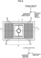
- FIG. 6 illustrates the frame member 35 that has a hollow frame shape. Alternatively, the frame member 35 may have a U-shape.
- the x'-y'-z' coordinate system is a coordinate system of the optical scanning device 28 and the X-Y-Z coordinate system is a coordinate system of the mobile object 1.
- the x' direction represents the longitudinal direction of the optical scanning device 28 that has an oblong rectangular shape
- the y' direction represents the direction of the thickness of the substrate of the optical scanning device 28
- the z' direction represents the lateral direction of the optical scanning device 28.
- the X direction represents the direction in which the mobile object travels
- the Y direction represents the horizontal direction of the mobile object
- the Z direction represents the vertical direction of the mobile object.
- the frame member 35 has multiple folded areas that support a tortuous beam pair 36 that is formed tortuously.
- the tortuous beam pair 36 is an exemplary driver and is divided into alternate beams 36a and beams 36b.
- piezoelectric members (piezoelectric layers) 37 that are independent of each other are respectively provided on the beam 36a and the beam 37b that are adjacent to each other.
- the movable mirror unit 34 has a small diameter of approximately 1 mm and has a small rotational moment, which makes it possible to increase the resonant frequency in the direction of torsion (direction of rotation) and obtain a large amplitude easily.
- the anti-vibration members 21a to 21c are formed of, for example, silicon rubber or butyl rubber.
- FIG. 7 represents vibration transmission characteristics of the anti-vibration members 21a to 21c.
- the horizontal axis in FIG. 7 represents frequency (Hz) and the vertical axis represents transmissibility.
- the mobile object 1 of the embodiment is designed such that the resonant frequency of the anti-vibration members 21a to 21c that are determined by the mass of the display image forming device 20 and the rigidity of the anti-vibration members 21a to 21c is within a range at or above 100 Hz. Near the resonant frequency, the transmissibility is larger than "1" represented by the dotted line in FIG. 7 .
- FIG. 8 represents vibrational characteristics of the mobile object 1.
- the horizontal axis of FIG. 8 represents frequency (Hz) and the vertical axis represents acceleration power spectral density (PSD).
- Hz frequency
- PSD acceleration power spectral density
- FIG. 8 in general, disturbance vibration that is transmitted from the mobile object 1 to the head-up display device 10 increases up to 100 Hz. For this reason, in the mobile object 1 of the embodiment, the resonant frequency of the anti-vibration members 21a to 21c is set at or above 100 Hz.
- the anti-vibration members 21a to 21c resonate, it is possible to prevent inconvenience in that the disturbance increases the vibration amplitude and maintain high positional accuracy between the display image forming device 20 and the latter optical elements (the reflective mirror 14, the projection mirror 11, the ejection window 12, and the front window glass 3).
- FIG. 9 represents vibration response characteristics of the optical scanning device 28 near a primary resonance point.
- the horizontal axis of FIG. 9 represents frequency (Hz) and the vertical axis of FIG. 9 represents response level.
- the optical scanning device 28 is supported by a spring structure as described above and thus has a steep response peak as represented by the solid line in FIG. 9 .
- the primary resonance is excited by disturbance vibration in the "y' direction" that is the direction of the thickness of the substrate of the optical scanning device 28 illustrated in FIG. 6 .
- the optical scanning device 28 resonates and two-dimensional scanning is disturbed and thus a blur occurs in the display image. This is because, in the "y' direction" of the optical scanning device 28, the rigidity is low and thus the resonant frequency lowers and the amount of displacement increases.
- FIG. 10 illustrates exemplary overall effective values of the attachment parts of the head-up display device 10 on the mobile object 1 in the X, Y and Z directions.
- the horizontal axis represents frequency (Hz) and the vertical axis represents overall effective value.
- An overall effective value is a value representing a magnitude of acceleration of a whole frequency range.
- the white bar represents an overall effective value of vibration in the anteroposterior direction (X direction) of the mobile object 1
- a bar with rightward slashes represents an overall effective value of vibration in the horizontal direction (Y direction) of the mobile object 1
- a bar with leftward slashes represents an overall effective value of vibration in the vertical direction (the gravitational direction: Z direction) of the mobile object 1.
- the overall effective value of vibration of the mobile object 1 is smaller in the Y direction (horizontal direction) than in the X direction (anteroposterior direction) and the Z direction (the center-of-gravity direction). This is because, while the X direction and the Y direction of the mobile object 1 are directions in which the mobile object 1 is susceptible to effects of unevenness of the road surface or variation in the vehicle speed, the Y direction is a direction that are not susceptible to these effects.
- the head-up display device 10 is attached to the mobile object 1 of the embodiment by fastening the attachment parts 41a to 41d with screws to the attachment bracket 42 and the attachment bracket 44 such that the horizontal direction (Y direction) in which vibration that is caused by the mobile object 1 is at or under a predetermined value and the reflective surface of the movable mirror unit 34 of the optical scanning device 28 are approximately perpendicular to each other.
- the optical scanning device 28 is provided in the head-up display device 10 such that the direction in which the optical scanning device 28 is the most susceptible to disturbance vibration from the mobile object 1 and the direction in which vibration that occurs in the mobile object 1 is the smallest, among the directions corresponding to the shape of the substrate of the optical scanning device 28, match.
- the display image forming device 20 is provided on the mobile object 1 such that the direction of the thickness (y' direction) of the substrate of the optical scanning device 28 in which the optical scanning device 28 is susceptible to the disturbance vibration and the horizontal direction (Y direction) that is a direction of the mobile object 1 in which the disturbance vibration reduces match each other.
- the horizontal direction (Y direction) of the mobile object 1 is an exemplary lateral direction that is parallel to the ground.
- the optical scanning device 28 is provided in the casing 30 of the display image forming device 20 such that the straight line in the longitudinal direction and the straight line connecting the anti-vibration member 21a and the anti-vibration member 21b are parallel to each other.
- the casing 30 is provided, being fixed to the mobile object 1 such that the straight line connecting the anti-vibration member 21a and the anti-vibration member 21b match the direction in which the mobile object 1 travels (X direction). Fixing the casing 30 of the display image forming device 20 to the mobile object 1 as described above makes it possible to, as illustrated in FIG. 4 , fix the display image forming device 20 to the mobile object 1 with the direction of the thickness of the substrate of the optical scanning device 28 (y' direction) and the horizontal direction (Y direction) of the mobile object 1 matching each other.
- the head-up display device 10 enabling preferable display images without blur in image due to resonance of the optical scanning device 28.
- Designing the anti-vibration members 21a to 21c with vibration damping characteristics that attenuate primary resonant frequency components (low-frequency component) of the optical scanning device 28 makes it possible to further inhibit disturbance vibration from being transmitted from the mobile object 1 to the optical scanning device 28.
- the mobile object 1 of the embodiment it is possible to inhibit transmission of vibration of the low frequency band to the optical scanning device 28 as described above. For this reason, even when lowering rigidity of the spring structure that supports the movable mirror unit 34 of the optical scanning device 28 enables the movable mirror unit 34 to have a natural resonant frequency of a low-frequency band, it is possible to prevent inconvenience in that the optical scanning device 28 resonates in the low frequency band. It is also possible to increase the angle of view by lowering rigidity of the spring structure that supports the movable mirror unit 34 without obstacle. Accordingly, it is possible to provide the head-up display device 10 with a wide angle of view and without image blur.
- FIG. 11 represents a result of evaluating changes in angle of a display image of the head-up display device 10 that are obtained when the "y' direction that is the direction of the thickness of the substrate of the optical scanning device 28 is gradually shifted from the "Y direction” that is the horizontal direction of the mobile object 1.
- the driver While the mobile object 1 is traveling, in general, the driver (operator) is able to recognize a change of about 5 min in the angle of display of a subject. For this reason, in order to prevent blur in the display image of the head-up display device 10, it is necessary to keep the image vibration angle at 5 mn or smaller, i.e., within an allowable amplitude range that is represented by the dotted line in FIG. 11 .
- the head-up display device 10 is attached to the mobile object 1 such that the angle that is formed by the straight line in a direction approximately orthogonal to the reflective surface of the movable mirror unit 34 of the optical scanning device 28 and the straight line in the ′′′y direction" in which vibration caused by the mobile object 1 is at or under the predetermined value is an angle within the allowable amplitude range that disables the operator to recognize a swing that is caused in the projected image due to vibration caused by the mobile object 1.
- the optical scanning device 28 is arranged such that the angle that is formed by the straight line in the "y' direction” that is the direction of the thickness of the substrate of the optical scanning device 28 and the straight line in the "Y direction” that is the horizontal direction of the mobile object 1 is 30 degrees or smaller.
- the display image forming device 20 is fixed to the mobile object 1 with the direction (y' direction) of the thickness of the substrate of the optical scanning device 28 and the horizontal direction (Y direction) of the mobile object 1 matching each other. Accordingly, it is possible to provide the head-up display device 10 that prevents inconvenience in that low-frequency vibration is transmitted from the mobile object 1 to the optical scanning device 28, thereby enabling a preferable display image without image blur.
- the display image forming device 20 is fixed to the mobile object 1 via the anti-vibration members 21a to 21c that have resonance characteristics with respect to frequencies equal to or higher than the resonant frequency in the horizontal direction (Y direction) of the mobile object 1 and that damp vibration of frequencies under the resonant frequency in the horizontal direction (Y direction) of the mobile object 1.
- the head-up display device 10 that enables significant reduction of vibration that is transmitted from the mobile object 1 to the head-up display device 10 and a wider angle of view without image blur.
- each of the above-described embodiments is represented as an example and is not intended to limit the scope of the invention.
- the three anti-vibration members 21a to 21c are used.
- four or five anti-vibration members may be used.
- a fluid damper may be used as the anti-vibration members 21a to 21c or the anti-vibration members 21a to 21c having a grommet shape may be used. Any of the cases enables the same effect as that described above.
- a light emitting diode may be used as each of the laser light sources 22 to 24 and an optical scanning device including the movable mirror units 34 may be used as the optical scanning device 28. This case also enables the same effect as that described above.
- the mobile object 1 is a vehicle.
- the mobile object 1 may be another mobile object, such as an airplane or a ship.
- the above-described embodiment is an example in which the present invention is applied to a head-up display device.
- the present invention may be applied to a so-called projector device. Any of the cases enables the same effect as that described above.
- the embodiment produces an effect that it is possible to reduce vibration that is transmitted from the setting object to the projection device.
Landscapes
- Physics & Mathematics (AREA)
- General Physics & Mathematics (AREA)
- Optics & Photonics (AREA)
- Engineering & Computer Science (AREA)
- Chemical & Material Sciences (AREA)
- Combustion & Propulsion (AREA)
- Transportation (AREA)
- Mechanical Engineering (AREA)
- Instrument Panels (AREA)
Claims (7)
- Projektionsvorrichtung (10), die Folgendes umfasst:eine Lichtquelle (22, 23, 24);eine optische Abtasteinheit (28), die eine Basiseinheit (35), einen an der Basiseinheit (35) befestigten Treiber (36) und eine reflektierende Einheit (34) enthält, die von dem Treiber (36) getragen wird und die die reflektierende Einheit (34) antreibt, um Licht von der Lichtquelle (22, 23, 24) abzutasten; undeine abgetastete Einheit (29), die dafür konfiguriert ist, mit dem Licht von der optischen Abtasteinheit (28) abgetastet zu werden, so dass ein Projektionsbild auf der abgetasteten Einheit (29) gebildet wird,wobei die Projektionsvorrichtung (10) ferner eine Anbringungseinheit (41) zum Anbringen der Projektionsvorrichtung (10) an einer Einstelleinheit (44) eines Einstellobjekts umfasst, auf das die Projektionsvorrichtung (10) eingestellt wird, unddadurch gekennzeichnet, dass die Anbringungseinheit (41) die Projektionsvorrichtung (10) an der Einstelleinheit (44) derart anbringt, dass eine seitliche Richtung des Einstellobjekts, in der die durch das Einstellobjekt verursachte Vibration gleich oder kleiner als ein vorbestimmter Wert ist, und eine Reflexionsfläche der Reflexionseinheit (34) annähernd senkrecht zueinander stehen, wobei die seitliche Richtung des Einstellobjekts parallel zum Boden und senkrecht zu einer Richtung ist, in der das Einstellobjekt zum Fahren konfiguriert ist.
- Projektionsvorrichtung (10) nach Anspruch 1, wobei die optische Abtasteinheit (28) in der Richtung annähernd senkrecht zur Reflexionsfläche der Reflexionseinheit (34) durch das Einstellobjekt in Schwingung versetzt werden kann.
- Projektionsvorrichtung (10) nach Anspruch 1 oder 2, wobei eine Lichtquelleneinheit (20) mit der Lichtquelle (22, 23, 24) und der optischen Abtasteinheit (28) über ein Antivibrationselement (21) an einem Gehäuse der Projektionsvorrichtung (10) befestigt ist, das schwingungsdämpfende Eigenschaften aufweist, die primäre Resonanzfrequenzkomponenten der Projektionsvorrichtung (10) abschwächen.
- Projektionsvorrichtung (10) nach Anspruch 3, wobei drei Antivibrationselemente (21a, 21b, 21c) vorhanden sind und die drei Antivibrationselemente (21a, 21b, 21c) in Form eines Dreiecks angeordnet sind, und
die Lichtquelleneinheit (20) über die drei Antivibrationselemente (21a, 21b, 21c) an dem Gehäuse der Projektionsvorrichtung (10) befestigt ist, so dass der Schwerpunkt der Lichtquelleneinheit (20) mit dem Schwerpunkt des Dreiecks auf einer X-Y-Ebene, einer Y-Z-Ebene und einer Z-X-Ebene übereinstimmt. - Projektionsvorrichtung (10) nach einem der Ansprüche 1 bis 4, wobei die Befestigungseinheit (41) die Projektionsvorrichtung (10) an der Einstelleinheit (44) befestigt, so dass ein Winkel, der von einer Geraden in der Richtung annähernd senkrecht zur reflektierenden Oberfläche der Reflexionseinheit (34) und einer Geraden in einer Richtung einer Dicke eines Substrats der optischen Abtasteinheit (28) gebildet wird, ein Winkel innerhalb eines zulässigen Amplitudenbereichs ist, der ein Bereich ist, der es einem Bediener unmöglich macht, ein Schwingen zu erfassen, das in dem Projektionsbild aufgrund der durch das Einstellobjekt verursachten Vibration verursacht wird.
- Bewegliches Objekt (1), das seine physische Position ändert, wobei an dem beweglichen Objekt (1) die Projektionsvorrichtung (10) nach einem der Ansprüche 1 bis 5 angebracht ist.
- Verfahren zum Einstellen von Folgendem: einer Projektionsvorrichtung (10) mit einer Lichtquelle (22, 23, 24); einer optischen Abtasteinheit (28), die eine Basiseinheit (35), einen an der Basiseinheit (35) befestigten Treiber (36) und eine von dem Treiber (36) getragene Reflexionseinheit (34) umfasst und die die Reflexionseinheit (34) antreibt, um Licht von der Lichtquelle (22, 23, 24) abzutasten; und einer abgetasteten Einheit (29), die mit dem Licht von der optischen Abtasteinheit (28) abgetastet wird, so dass ein Projektionsbild auf der abgetasteten Einheit (29) gebildet wird, wobei das Verfahren Folgendes umfasst:
durch eine Anbringungseinheit (41) zum Anbringen der Projektionsvorrichtung an einer Einstelleinheit (44) eines Einstellobjekts, auf das die Projektionsvorrichtung (10) eingestellt wird, Anbringen der Projektionsvorrichtung (10) an der Einstelleinheit (44) so dass eine seitliche Richtung des Einstellobjekts, in der die durch das Einstellobjekt verursachte Vibration gleich oder kleiner als ein vorbestimmter Wert ist, und eine reflektierende Oberfläche der reflektierenden Einheit (34) annähernd senkrecht zueinander stehen, wobei die seitliche Richtung des Einstellobjekts parallel zum Boden und senkrecht zu einer Richtung ist, in der das Einstellobjekt zum Fahren konfiguriert ist.
Applications Claiming Priority (1)
| Application Number | Priority Date | Filing Date | Title |
|---|---|---|---|
| JP2018044792A JP7047491B2 (ja) | 2018-03-12 | 2018-03-12 | 投射装置、移動体および投射装置の設置方法 |
Publications (2)
| Publication Number | Publication Date |
|---|---|
| EP3540509A1 EP3540509A1 (de) | 2019-09-18 |
| EP3540509B1 true EP3540509B1 (de) | 2023-05-03 |
Family
ID=65717933
Family Applications (1)
| Application Number | Title | Priority Date | Filing Date |
|---|---|---|---|
| EP19161097.1A Active EP3540509B1 (de) | 2018-03-12 | 2019-03-06 | Projektionsvorrichtung, mobiles objekt und verfahren zur einstellung der projektionsvorrichtung |
Country Status (3)
| Country | Link |
|---|---|
| US (1) | US11036047B2 (de) |
| EP (1) | EP3540509B1 (de) |
| JP (1) | JP7047491B2 (de) |
Families Citing this family (2)
| Publication number | Priority date | Publication date | Assignee | Title |
|---|---|---|---|---|
| EP3671315B1 (de) | 2018-11-28 | 2022-11-30 | Ricoh Company, Ltd. | Anzeigevorrichtung und mobiles objekt |
| FR3102412A1 (fr) * | 2019-10-23 | 2021-04-30 | Psa Automobiles Sa | Combiné d’instrumentation pour un véhicule |
Family Cites Families (9)
| Publication number | Priority date | Publication date | Assignee | Title |
|---|---|---|---|---|
| US20040184124A1 (en) * | 2002-11-13 | 2004-09-23 | Olympus Corporation | Optical deflection device |
| JP6340807B2 (ja) | 2014-02-05 | 2018-06-13 | 株式会社リコー | 画像表示装置及び移動体 |
| JP6369038B2 (ja) | 2014-02-05 | 2018-08-08 | 株式会社リコー | ヘッドアップディスプレイ装置 |
| JP6459446B2 (ja) | 2014-11-28 | 2019-01-30 | アイシン・エィ・ダブリュ株式会社 | 虚像表示装置 |
| US10491866B2 (en) | 2015-08-26 | 2019-11-26 | Ricoh Company, Ltd. | Actuator controlling device, drive system, video device, image projection device, and actuator controlling method |
| JP6604816B2 (ja) | 2015-10-28 | 2019-11-13 | スタンレー電気株式会社 | 映像投射装置及びmemsミラーの制御方法 |
| JP6820501B2 (ja) * | 2017-02-20 | 2021-01-27 | パナソニックIpマネジメント株式会社 | 画像表示装置 |
| EP3370103A1 (de) | 2017-03-02 | 2018-09-05 | Ricoh Company Ltd. | Anzeigevorrichtung und vorrichtung |
| EP3376280B1 (de) | 2017-03-15 | 2023-04-05 | Ricoh Company, Ltd. | Anzeigevorrichtung und vorrichtung |
-
2018
- 2018-03-12 JP JP2018044792A patent/JP7047491B2/ja not_active Expired - Fee Related
-
2019
- 2019-03-06 EP EP19161097.1A patent/EP3540509B1/de active Active
- 2019-03-07 US US16/294,964 patent/US11036047B2/en active Active
Also Published As
| Publication number | Publication date |
|---|---|
| EP3540509A1 (de) | 2019-09-18 |
| US11036047B2 (en) | 2021-06-15 |
| JP2019159066A (ja) | 2019-09-19 |
| JP7047491B2 (ja) | 2022-04-05 |
| US20190278084A1 (en) | 2019-09-12 |
Similar Documents
| Publication | Publication Date | Title |
|---|---|---|
| JP4856758B2 (ja) | 統合型および統合型フォトニクスモジュールを用いたデバイス | |
| JP6402278B2 (ja) | 投写型表示装置 | |
| WO2010044205A1 (ja) | 走査型画像表示装置 | |
| JP6369038B2 (ja) | ヘッドアップディスプレイ装置 | |
| US10031336B2 (en) | Image display device | |
| JP6760188B2 (ja) | ヘッドアップディスプレイ装置 | |
| EP3540509B1 (de) | Projektionsvorrichtung, mobiles objekt und verfahren zur einstellung der projektionsvorrichtung | |
| US10409063B2 (en) | Image display device | |
| JPH06308431A (ja) | 像安定化装置 | |
| EP3660577B1 (de) | Anzeigevorrichtung und mobiler körper | |
| JPH01293239A (ja) | ヘッドアップディスプレイ装置 | |
| JP2020190617A (ja) | 虚像表示装置 | |
| CN119270508B (zh) | 抬头显示器防抖光路、抗抖动方法与抗抖动检测方法 | |
| JP6579230B2 (ja) | ヘッドアップディスプレイ装置 | |
| JP2022187090A (ja) | プロジェクタ装置 | |
| JP2024108407A (ja) | 可動装置の台座、可動システム、画像投影装置、距離測定装置、音響装置および振動子 | |
| KR20140140321A (ko) | 마이크로디스플레이 장치 |
Legal Events
| Date | Code | Title | Description |
|---|---|---|---|
| PUAI | Public reference made under article 153(3) epc to a published international application that has entered the european phase |
Free format text: ORIGINAL CODE: 0009012 |
|
| STAA | Information on the status of an ep patent application or granted ep patent |
Free format text: STATUS: REQUEST FOR EXAMINATION WAS MADE |
|
| 17P | Request for examination filed |
Effective date: 20190306 |
|
| AK | Designated contracting states |
Kind code of ref document: A1 Designated state(s): AL AT BE BG CH CY CZ DE DK EE ES FI FR GB GR HR HU IE IS IT LI LT LU LV MC MK MT NL NO PL PT RO RS SE SI SK SM TR |
|
| AX | Request for extension of the european patent |
Extension state: BA ME |
|
| STAA | Information on the status of an ep patent application or granted ep patent |
Free format text: STATUS: EXAMINATION IS IN PROGRESS |
|
| 17Q | First examination report despatched |
Effective date: 20200908 |
|
| INTG | Intention to grant announced |
Effective date: 20221215 |
|
| RIN1 | Information on inventor provided before grant (corrected) |
Inventor name: GOTOH, TOKIKO |
|
| GRAS | Grant fee paid |
Free format text: ORIGINAL CODE: EPIDOSNIGR3 |
|
| STAA | Information on the status of an ep patent application or granted ep patent |
Free format text: STATUS: GRANT OF PATENT IS INTENDED |
|
| GRAA | (expected) grant |
Free format text: ORIGINAL CODE: 0009210 |
|
| STAA | Information on the status of an ep patent application or granted ep patent |
Free format text: STATUS: THE PATENT HAS BEEN GRANTED |
|
| AK | Designated contracting states |
Kind code of ref document: B1 Designated state(s): AL AT BE BG CH CY CZ DE DK EE ES FI FR GB GR HR HU IE IS IT LI LT LU LV MC MK MT NL NO PL PT RO RS SE SI SK SM TR |
|
| REG | Reference to a national code |
Ref country code: GB Ref legal event code: FG4D |
|
| REG | Reference to a national code |
Ref country code: AT Ref legal event code: REF Ref document number: 1565141 Country of ref document: AT Kind code of ref document: T Effective date: 20230515 Ref country code: CH Ref legal event code: EP |
|
| REG | Reference to a national code |
Ref country code: DE Ref legal event code: R096 Ref document number: 602019028237 Country of ref document: DE |
|
| REG | Reference to a national code |
Ref country code: IE Ref legal event code: FG4D |
|
| P01 | Opt-out of the competence of the unified patent court (upc) registered |
Effective date: 20230505 |
|
| REG | Reference to a national code |
Ref country code: LT Ref legal event code: MG9D |
|
| REG | Reference to a national code |
Ref country code: NL Ref legal event code: MP Effective date: 20230503 |
|
| REG | Reference to a national code |
Ref country code: AT Ref legal event code: MK05 Ref document number: 1565141 Country of ref document: AT Kind code of ref document: T Effective date: 20230503 |
|
| PG25 | Lapsed in a contracting state [announced via postgrant information from national office to epo] |
Ref country code: SE Free format text: LAPSE BECAUSE OF FAILURE TO SUBMIT A TRANSLATION OF THE DESCRIPTION OR TO PAY THE FEE WITHIN THE PRESCRIBED TIME-LIMIT Effective date: 20230503 Ref country code: PT Free format text: LAPSE BECAUSE OF FAILURE TO SUBMIT A TRANSLATION OF THE DESCRIPTION OR TO PAY THE FEE WITHIN THE PRESCRIBED TIME-LIMIT Effective date: 20230904 Ref country code: NO Free format text: LAPSE BECAUSE OF FAILURE TO SUBMIT A TRANSLATION OF THE DESCRIPTION OR TO PAY THE FEE WITHIN THE PRESCRIBED TIME-LIMIT Effective date: 20230803 Ref country code: NL Free format text: LAPSE BECAUSE OF FAILURE TO SUBMIT A TRANSLATION OF THE DESCRIPTION OR TO PAY THE FEE WITHIN THE PRESCRIBED TIME-LIMIT Effective date: 20230503 Ref country code: ES Free format text: LAPSE BECAUSE OF FAILURE TO SUBMIT A TRANSLATION OF THE DESCRIPTION OR TO PAY THE FEE WITHIN THE PRESCRIBED TIME-LIMIT Effective date: 20230503 Ref country code: AT Free format text: LAPSE BECAUSE OF FAILURE TO SUBMIT A TRANSLATION OF THE DESCRIPTION OR TO PAY THE FEE WITHIN THE PRESCRIBED TIME-LIMIT Effective date: 20230503 |
|
| PG25 | Lapsed in a contracting state [announced via postgrant information from national office to epo] |
Ref country code: RS Free format text: LAPSE BECAUSE OF FAILURE TO SUBMIT A TRANSLATION OF THE DESCRIPTION OR TO PAY THE FEE WITHIN THE PRESCRIBED TIME-LIMIT Effective date: 20230503 Ref country code: PL Free format text: LAPSE BECAUSE OF FAILURE TO SUBMIT A TRANSLATION OF THE DESCRIPTION OR TO PAY THE FEE WITHIN THE PRESCRIBED TIME-LIMIT Effective date: 20230503 Ref country code: LV Free format text: LAPSE BECAUSE OF FAILURE TO SUBMIT A TRANSLATION OF THE DESCRIPTION OR TO PAY THE FEE WITHIN THE PRESCRIBED TIME-LIMIT Effective date: 20230503 Ref country code: LT Free format text: LAPSE BECAUSE OF FAILURE TO SUBMIT A TRANSLATION OF THE DESCRIPTION OR TO PAY THE FEE WITHIN THE PRESCRIBED TIME-LIMIT Effective date: 20230503 Ref country code: IS Free format text: LAPSE BECAUSE OF FAILURE TO SUBMIT A TRANSLATION OF THE DESCRIPTION OR TO PAY THE FEE WITHIN THE PRESCRIBED TIME-LIMIT Effective date: 20230903 Ref country code: HR Free format text: LAPSE BECAUSE OF FAILURE TO SUBMIT A TRANSLATION OF THE DESCRIPTION OR TO PAY THE FEE WITHIN THE PRESCRIBED TIME-LIMIT Effective date: 20230503 Ref country code: GR Free format text: LAPSE BECAUSE OF FAILURE TO SUBMIT A TRANSLATION OF THE DESCRIPTION OR TO PAY THE FEE WITHIN THE PRESCRIBED TIME-LIMIT Effective date: 20230804 |
|
| PG25 | Lapsed in a contracting state [announced via postgrant information from national office to epo] |
Ref country code: FI Free format text: LAPSE BECAUSE OF FAILURE TO SUBMIT A TRANSLATION OF THE DESCRIPTION OR TO PAY THE FEE WITHIN THE PRESCRIBED TIME-LIMIT Effective date: 20230503 |
|
| PG25 | Lapsed in a contracting state [announced via postgrant information from national office to epo] |
Ref country code: SK Free format text: LAPSE BECAUSE OF FAILURE TO SUBMIT A TRANSLATION OF THE DESCRIPTION OR TO PAY THE FEE WITHIN THE PRESCRIBED TIME-LIMIT Effective date: 20230503 |
|
| PG25 | Lapsed in a contracting state [announced via postgrant information from national office to epo] |
Ref country code: SM Free format text: LAPSE BECAUSE OF FAILURE TO SUBMIT A TRANSLATION OF THE DESCRIPTION OR TO PAY THE FEE WITHIN THE PRESCRIBED TIME-LIMIT Effective date: 20230503 Ref country code: SK Free format text: LAPSE BECAUSE OF FAILURE TO SUBMIT A TRANSLATION OF THE DESCRIPTION OR TO PAY THE FEE WITHIN THE PRESCRIBED TIME-LIMIT Effective date: 20230503 Ref country code: RO Free format text: LAPSE BECAUSE OF FAILURE TO SUBMIT A TRANSLATION OF THE DESCRIPTION OR TO PAY THE FEE WITHIN THE PRESCRIBED TIME-LIMIT Effective date: 20230503 Ref country code: EE Free format text: LAPSE BECAUSE OF FAILURE TO SUBMIT A TRANSLATION OF THE DESCRIPTION OR TO PAY THE FEE WITHIN THE PRESCRIBED TIME-LIMIT Effective date: 20230503 Ref country code: DK Free format text: LAPSE BECAUSE OF FAILURE TO SUBMIT A TRANSLATION OF THE DESCRIPTION OR TO PAY THE FEE WITHIN THE PRESCRIBED TIME-LIMIT Effective date: 20230503 Ref country code: CZ Free format text: LAPSE BECAUSE OF FAILURE TO SUBMIT A TRANSLATION OF THE DESCRIPTION OR TO PAY THE FEE WITHIN THE PRESCRIBED TIME-LIMIT Effective date: 20230503 |
|
| REG | Reference to a national code |
Ref country code: DE Ref legal event code: R097 Ref document number: 602019028237 Country of ref document: DE |
|
| PLBE | No opposition filed within time limit |
Free format text: ORIGINAL CODE: 0009261 |
|
| STAA | Information on the status of an ep patent application or granted ep patent |
Free format text: STATUS: NO OPPOSITION FILED WITHIN TIME LIMIT |
|
| 26N | No opposition filed |
Effective date: 20240206 |
|
| PGFP | Annual fee paid to national office [announced via postgrant information from national office to epo] |
Ref country code: DE Payment date: 20240320 Year of fee payment: 6 Ref country code: GB Payment date: 20240320 Year of fee payment: 6 |
|
| PG25 | Lapsed in a contracting state [announced via postgrant information from national office to epo] |
Ref country code: SI Free format text: LAPSE BECAUSE OF FAILURE TO SUBMIT A TRANSLATION OF THE DESCRIPTION OR TO PAY THE FEE WITHIN THE PRESCRIBED TIME-LIMIT Effective date: 20230503 |
|
| PG25 | Lapsed in a contracting state [announced via postgrant information from national office to epo] |
Ref country code: SI Free format text: LAPSE BECAUSE OF FAILURE TO SUBMIT A TRANSLATION OF THE DESCRIPTION OR TO PAY THE FEE WITHIN THE PRESCRIBED TIME-LIMIT Effective date: 20230503 Ref country code: IT Free format text: LAPSE BECAUSE OF FAILURE TO SUBMIT A TRANSLATION OF THE DESCRIPTION OR TO PAY THE FEE WITHIN THE PRESCRIBED TIME-LIMIT Effective date: 20230503 |
|
| PGFP | Annual fee paid to national office [announced via postgrant information from national office to epo] |
Ref country code: FR Payment date: 20240328 Year of fee payment: 6 |
|
| REG | Reference to a national code |
Ref country code: CH Ref legal event code: PL |
|
| PG25 | Lapsed in a contracting state [announced via postgrant information from national office to epo] |
Ref country code: BG Free format text: LAPSE BECAUSE OF FAILURE TO SUBMIT A TRANSLATION OF THE DESCRIPTION OR TO PAY THE FEE WITHIN THE PRESCRIBED TIME-LIMIT Effective date: 20230503 |
|
| PG25 | Lapsed in a contracting state [announced via postgrant information from national office to epo] |
Ref country code: LU Free format text: LAPSE BECAUSE OF NON-PAYMENT OF DUE FEES Effective date: 20240306 |
|
| PG25 | Lapsed in a contracting state [announced via postgrant information from national office to epo] |
Ref country code: MC Free format text: LAPSE BECAUSE OF FAILURE TO SUBMIT A TRANSLATION OF THE DESCRIPTION OR TO PAY THE FEE WITHIN THE PRESCRIBED TIME-LIMIT Effective date: 20230503 |
|
| PG25 | Lapsed in a contracting state [announced via postgrant information from national office to epo] |
Ref country code: MC Free format text: LAPSE BECAUSE OF FAILURE TO SUBMIT A TRANSLATION OF THE DESCRIPTION OR TO PAY THE FEE WITHIN THE PRESCRIBED TIME-LIMIT Effective date: 20230503 Ref country code: LU Free format text: LAPSE BECAUSE OF NON-PAYMENT OF DUE FEES Effective date: 20240306 Ref country code: BG Free format text: LAPSE BECAUSE OF FAILURE TO SUBMIT A TRANSLATION OF THE DESCRIPTION OR TO PAY THE FEE WITHIN THE PRESCRIBED TIME-LIMIT Effective date: 20230503 |
|
| REG | Reference to a national code |
Ref country code: BE Ref legal event code: MM Effective date: 20240331 |
|
| PG25 | Lapsed in a contracting state [announced via postgrant information from national office to epo] |
Ref country code: BE Free format text: LAPSE BECAUSE OF NON-PAYMENT OF DUE FEES Effective date: 20240331 |
|
| PG25 | Lapsed in a contracting state [announced via postgrant information from national office to epo] |
Ref country code: IE Free format text: LAPSE BECAUSE OF NON-PAYMENT OF DUE FEES Effective date: 20240306 |
|
| PG25 | Lapsed in a contracting state [announced via postgrant information from national office to epo] |
Ref country code: IE Free format text: LAPSE BECAUSE OF NON-PAYMENT OF DUE FEES Effective date: 20240306 Ref country code: BE Free format text: LAPSE BECAUSE OF NON-PAYMENT OF DUE FEES Effective date: 20240331 Ref country code: CH Free format text: LAPSE BECAUSE OF NON-PAYMENT OF DUE FEES Effective date: 20240331 |
|
| PG25 | Lapsed in a contracting state [announced via postgrant information from national office to epo] |
Ref country code: CY Free format text: LAPSE BECAUSE OF FAILURE TO SUBMIT A TRANSLATION OF THE DESCRIPTION OR TO PAY THE FEE WITHIN THE PRESCRIBED TIME-LIMIT; INVALID AB INITIO Effective date: 20190306 |
|
| PG25 | Lapsed in a contracting state [announced via postgrant information from national office to epo] |
Ref country code: HU Free format text: LAPSE BECAUSE OF FAILURE TO SUBMIT A TRANSLATION OF THE DESCRIPTION OR TO PAY THE FEE WITHIN THE PRESCRIBED TIME-LIMIT; INVALID AB INITIO Effective date: 20190306 |
|
| REG | Reference to a national code |
Ref country code: DE Ref legal event code: R119 Ref document number: 602019028237 Country of ref document: DE |
|
| GBPC | Gb: european patent ceased through non-payment of renewal fee |
Effective date: 20250306 |
|
| PG25 | Lapsed in a contracting state [announced via postgrant information from national office to epo] |
Ref country code: TR Free format text: LAPSE BECAUSE OF FAILURE TO SUBMIT A TRANSLATION OF THE DESCRIPTION OR TO PAY THE FEE WITHIN THE PRESCRIBED TIME-LIMIT Effective date: 20230503 |
|
| PG25 | Lapsed in a contracting state [announced via postgrant information from national office to epo] |
Ref country code: DE Free format text: LAPSE BECAUSE OF NON-PAYMENT OF DUE FEES Effective date: 20251001 |
|
| PG25 | Lapsed in a contracting state [announced via postgrant information from national office to epo] |
Ref country code: GB Free format text: LAPSE BECAUSE OF NON-PAYMENT OF DUE FEES Effective date: 20250306 |
|
| PG25 | Lapsed in a contracting state [announced via postgrant information from national office to epo] |
Ref country code: FR Free format text: LAPSE BECAUSE OF NON-PAYMENT OF DUE FEES Effective date: 20250331 |