EP3540446A1 - Measurement system and method for operating a measurement system - Google Patents
Measurement system and method for operating a measurement system Download PDFInfo
- Publication number
- EP3540446A1 EP3540446A1 EP18161600.4A EP18161600A EP3540446A1 EP 3540446 A1 EP3540446 A1 EP 3540446A1 EP 18161600 A EP18161600 A EP 18161600A EP 3540446 A1 EP3540446 A1 EP 3540446A1
- Authority
- EP
- European Patent Office
- Prior art keywords
- probe unit
- unit
- measurement
- measurement system
- measurement device
- Prior art date
- Legal status (The legal status is an assumption and is not a legal conclusion. Google has not performed a legal analysis and makes no representation as to the accuracy of the status listed.)
- Granted
Links
Images
Classifications
-
- G—PHYSICS
- G01—MEASURING; TESTING
- G01R—MEASURING ELECTRIC VARIABLES; MEASURING MAGNETIC VARIABLES
- G01R1/00—Details of instruments or arrangements of the types included in groups G01R5/00 - G01R13/00 and G01R31/00
- G01R1/02—General constructional details
- G01R1/06—Measuring leads; Measuring probes
- G01R1/067—Measuring probes
- G01R1/06788—Hand-held or hand-manipulated probes, e.g. for oscilloscopes or for portable test instruments
-
- G—PHYSICS
- G01—MEASURING; TESTING
- G01D—MEASURING NOT SPECIALLY ADAPTED FOR A SPECIFIC VARIABLE; ARRANGEMENTS FOR MEASURING TWO OR MORE VARIABLES NOT COVERED IN A SINGLE OTHER SUBCLASS; TARIFF METERING APPARATUS; MEASURING OR TESTING NOT OTHERWISE PROVIDED FOR
- G01D7/00—Indicating measured values
-
- G—PHYSICS
- G01—MEASURING; TESTING
- G01R—MEASURING ELECTRIC VARIABLES; MEASURING MAGNETIC VARIABLES
- G01R13/00—Arrangements for displaying electric variables or waveforms
- G01R13/02—Arrangements for displaying electric variables or waveforms for displaying measured electric variables in digital form
-
- G—PHYSICS
- G01—MEASURING; TESTING
- G01R—MEASURING ELECTRIC VARIABLES; MEASURING MAGNETIC VARIABLES
- G01R23/00—Arrangements for measuring frequencies; Arrangements for analysing frequency spectra
- G01R23/16—Spectrum analysis; Fourier analysis
-
- G—PHYSICS
- G08—SIGNALLING
- G08C—TRANSMISSION SYSTEMS FOR MEASURED VALUES, CONTROL OR SIMILAR SIGNALS
- G08C17/00—Arrangements for transmitting signals characterised by the use of a wireless electrical link
- G08C17/02—Arrangements for transmitting signals characterised by the use of a wireless electrical link using a radio link
-
- G—PHYSICS
- G01—MEASURING; TESTING
- G01R—MEASURING ELECTRIC VARIABLES; MEASURING MAGNETIC VARIABLES
- G01R1/00—Details of instruments or arrangements of the types included in groups G01R5/00 - G01R13/00 and G01R31/00
- G01R1/02—General constructional details
- G01R1/025—General constructional details concerning dedicated user interfaces, e.g. GUI, or dedicated keyboards
-
- G—PHYSICS
- G08—SIGNALLING
- G08C—TRANSMISSION SYSTEMS FOR MEASURED VALUES, CONTROL OR SIMILAR SIGNALS
- G08C2201/00—Transmission systems of control signals via wireless link
- G08C2201/30—User interface
-
- H—ELECTRICITY
- H01—ELECTRIC ELEMENTS
- H01Q—ANTENNAS, i.e. RADIO AERIALS
- H01Q13/00—Waveguide horns or mouths; Slot antennas; Leaky-waveguide antennas; Equivalent structures causing radiation along the transmission path of a guided wave
- H01Q13/08—Radiating ends of two-conductor microwave transmission lines, e.g. of coaxial lines, of microstrip lines
- H01Q13/085—Slot-line radiating ends
Definitions
- the detector unit comprises a first and a second interface, the first interface being configured to receive electromagnetic waves and to provide a measurement signal to the second interface.
- the first interface may be an interface for receiving radio frequency signals.
- the measurement device 16 may just forward the control signal to the second probe unit 14.
- the first probe unit 12 only controls the second probe unit 14.
- the operational parameters may comprise one or more selected from the group of: an operational status (e.g. "on” or “off”), a measurement activity status, and a measurement parameter such as a frequency to be measured and a bandwidth of a frequency band to be measured.
- an operational status e.g. "on” or “off”
- a measurement activity status e.g. "on” or "off”
- a measurement parameter such as a frequency to be measured and a bandwidth of a frequency band to be measured.
Landscapes
- Physics & Mathematics (AREA)
- General Physics & Mathematics (AREA)
- Engineering & Computer Science (AREA)
- Computer Networks & Wireless Communication (AREA)
- Mathematical Physics (AREA)
- Arrangements For Transmission Of Measured Signals (AREA)
Abstract
Description
- The invention concerns a measurement system as well as a method for operating a measurement system
- For certain measurements, several measurement probes may be connected to a main measurement device, wherein the probes may be located at a certain distance from the main measurement device.
- In prior art measurement systems, operational parameters of the measurement system are adjusted via a graphical user interface at the main measurement device. Therefore, the operator or rather the user of the measurement system always has to operate the main measurement device for adjusting the operational parameters. Thus, it is not possible for the user to adjust the operational parameters of the measurement system when he is not near to the main measurement device. This can cause various difficulties when configuring the probes, in particular a functional interaction between the probes. Particularly, the installation and setup of the measurement system may be time-consuming.
- Therefore, the object of the invention is to provide a measurement system as well as a method for operating a measurement system which improve the disadvantages of the state of the art.
- According to the invention, the problem is solved by a measurement system comprising a measurement device and at least a first probe unit and a second probe unit. The first probe unit and the second probe unit each are connected to the measurement device in a signal transmitting manner. At least one of the measurement device and the first probe unit comprises a control unit. The first probe unit comprises an interface module being configured to generate an input data signal and to provide the input data signal to the control unit. The control unit is configured to generate and provide a control signal at least to the second probe unit based on the input data signal.
- The invention is characterized in that a user input received via the first probe unit is processed to provide a control signal to at least the second probe unit. Therefore, a user may control the second probe unit (which is possible located a certain distance away from the first probe) without having to walk to the second probe or to the measurements device. This way, configuring the probe units, in particular a functional interaction between the probe units, is greatly simplified for the user. Of course, the first probe unit may also be controlled via the interface module, such that a user can control the first probe unit and the second probe unit while standing at the first probe unit.
- Moreover, the second probe unit may also comprise an interface module being configured similar to the interface module of the first probe unit, such that a user may control all probe units while standing at either one of them.
- Generally, the probe units are formed separately from each other. Hence, the measurement system comprises at least two separately formed probe units.
- In addition, the measurement device may be established separately with respect to the probe units so that the measurement system comprises at least two separately formed probe units as well as one separately formed measurement device.
- The first probe unit may be configured to perform analog or digital signal processing. The measurement device may be an oscilloscope, a logic analyzer and/or any other measurement device suitable for a particular measurement at hand. Moreover, the probe units may be connected to the measurement device tethered or wirelessly.
- According to one aspect, the control unit is configured to provide the control signal to the second probe unit and the measurement device. This way, the user may control both the second probe unit and the measurement device while standing at the first probe unit without leaving the first probe unit.
- According to another aspect, the measurement device is configured to forward the control signal generated by the first probe unit comprising the control unit. In other words, the measurement device serves as a central router forwarding the control signal to the probe units. There may be additional probe units connected to the measurement device, and the measurement device may be configured to forward the control signals only to the proper probe units to be controlled.
- In one embodiment of the invention, at least the second probe unit is configured to adjust an operational parameter based on the control signal. The operational parameters may comprise one or more selected from the group of: an operational status (e.g. "on" or "off"), a measurement activity status, a frequency to be measured and a bandwidth of a frequency band to be measured. If the control signal is also provided to the first probe unit and/or the measurement device, the first probe unit and/or the measurement device may also be configured to adjust an operational parameter. Accordingly, the operational parameter may relate to a measurement parameter, namely a parameter to be measured.
- The interface module may be configured to forward the input data signal to the measurement device. The measurement device may store the input data signal and/or visualize the input data signal via a graphical user interface.
- In a further aspect, at least one of the first and the second probe units comprises a detector unit being configured to at least one of detect and transmit electromagnetic signals. In particular, the detector unit is configured to detect and/or transmit electromagnetic signals such as radio frequency (RF) signals. For example, the detector unit may comprise an antenna, in particular a tapered slot (Vivaldi) antenna.
- In another embodiment of the invention, the detector unit comprises a first and a second interface, the first interface being configured to receive electromagnetic waves and to provide a measurement signal to the second interface. The first interface may be an interface for receiving radio frequency signals.
- According to a further aspect, the second interface is configured to generate a processed measurement signal based on the measurement signal. In other words, the second interface converts the measurement signal provided by the first interface to a signal suitable for the measurement device. Accordingly, the second interface may be configured to generate an analog processed measurement signal and/or a digital processed measurement signal, depending on the kind of signal the measurement device is configured to process.
- In another aspect, a frequency of the processed measurement signal is lower than a frequency of the received electromagnetic waves. Put another way, the processed measurement signal is down-converted from the measurement signal provided by the first interface.
- The control signal may also be forwarded to the first probe unit. Thus, both probe units may be controlled by the user while standing at the first probe unit.
- In a certain embodiment of the invention, the control signal comprises at least one control command selected from the group of: switch on at least one of the first probe unit, the second probe unit and the measurement device; switch off at least one of the first probe unit, the second probe unit and the measurement device; transmit data to at least one of the first probe unit, the second probe unit and the measurement device; and adjust a trigger condition.
- According to one aspect, the first probe unit comprises a monitoring unit being connected to the measurement device in a signal transmitting manner. Via the monitoring unit, operational parameters of the measurement system may be indicated to the user. The monitoring unit may indicate the operational parameters graphically, e.g. via a display, or by means of one or more status lights. Alternatively or additionally, the operational parameters may also be indicated acoustically, e.g. with predefined acoustic patterns
- According to another aspect, the monitoring unit is configured to indicate a status of at least one of the probe units. Thus, the user is informed about the status (e.g. "on" or "off") of the probe units without walking to the measurement device or other probe units.
- In another embodiment of the invention, the monitoring unit is configured to indicate a representation of the control signal. For example, the monitoring unit displays a representation of possible control commands, in particular in the form of a list or a drop-down menu. This way, configuring the probe units and/or the measurement device is facilitated.
- According to one embodiment, the measurement system, in particular the control unit, is configured to provide the control signal to the second probe unit and the measurement device.
- According to another embodiment, the measurement system, in particular the control unit, is configured to provide the control signal only to the second probe unit.
- An embodiment provides that the measurement device may comprise the control unit so that the measurement device receives the input data signal generated by the first probe unit, in particular its interface module. Then, the control unit of the measurement device generates and provides the respective control signal.
- Another embodiment provides that the first probe unit itself comprises the control unit so that the input data signal provided by the interface module is forwarded internally (within the first probe unit) to the integrated control unit that is configured to generate and provide the respective control signal.
- According to the invention the problem is also solved by a method for operating a measurement system, in particular a measurement system as described above, wherein the measurement system comprises a measurement device and at least a first probe unit and a second probe unit. The method comprises the following steps:
- receiving a user input via the first probe unit;
- generating an input data signal based on the user input;
- generating a control signal based on the input data signal; and
- adjusting at least one operational parameter of the second probe unit based on the control signal.
- Of course, also operational parameters of the first probe unit and/or the measurement device may be adjusted. With regards to the advantages, reference is made to the explanations given above.
- As mentioned above, the control signal is generated by the control unit which may be integrated in the measurement device and/or the first probe unit so that the control signal may be generated by the measurement device and/or the first probe unit.
- Moreover, the second probe unit or rather the second probe unit and the measurement device may be set appropriately by the control signal.
- The foregoing aspects and many of the attendant advantages of the claimed subject matter will become more readily appreciated as the same become better understood by reference to the following detailed description, when taken in conjunction with the accompanying drawings, wherein:
-
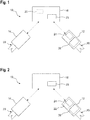
Fig. 1 shows a measurement system according to a first embodiment of a measurement system according to the invention; -
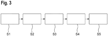
Fig. 2 shows a measurement system according to another embodiment of a measurement system according to the invention; and -
Fig. 3 shows a schematic flow chart of a method for operating a measurement system according to the invention. - The detailed description set forth below in connection with the appended drawings, where like numerals reference like elements, is intended as a description of various embodiments of the disclosed subject matter and is not intended to represent the only embodiments. Each embodiment described in this disclosure is provided merely as an example or illustration and should not be construed as preferred or advantageous over other embodiments. The illustrative examples provided herein are not intended to be exhaustive or to limit the claimed subject matter to the precise forms disclosed.
-
Figure 1 shows ameasurement system 10 comprising afirst probe unit 12, asecond probe unit 14 and ameasurement device 16 which are separately formed from each other. Themeasurement system 10 may also comprise additional probe units. - The
measurement device 16 may be an oscilloscope, a logic analyzer and/or any other measurement device suitable for a particular measurement at hand. - The
first probe unit 12 and thesecond probe unit 14 are connected to themeasurement device 16 in a signal transmitting manner (indicated by the dashed arrows inFigures 1 and 2 ), which may be tethered or wireless. - The
first probe unit 12 and thesecond probe unit 14 unit can each be configured to perform any kind of measurements. In the example shown inFigures 1 and 2 , thefirst probe unit 12 and thesecond probe unit 14 comprisedetector units detector units - At least one of the
detector units - The second interface is configured to process the measurement signal provided by the first interface. The second interface provides a processed measurement signal based on the measurement signal forwarded by the first interface, wherein the processed measurement signal may be an analog or a digital signal.
- In other words, the second interface converts the measurement signal provided by the first interface to a signal suitable for the
measurement device 16. Accordingly, the second interface may be configured to generate an analog processed measurement signal and/or a digital processed measurement signal, depending on the kind of signal themeasurement device 16 is configured to process. - The processed measurement signal may be down-converted from the measurement signal, i.e. a frequency of the processed measurement signal may be lower than a frequency of the received electromagnetic waves.
- The processed measurement signal can then be forwarded to the
measurement device 16, in particular by the second interface. - In the embodiment shown in
Figure 1 , themeasurement device 16 comprises acontrol unit 22, while in the embodiment shown inFigure 2 thefirst probe unit 12 comprises thecontrol unit 22. - An
interface module 24 is provided at thefirst probe unit 12. Via theinterface module 24, a user may input data and/or commands. Theinterface module 24 is configured to generate an input data signal based on the data and/or commands input by the user. - Of course, a second interface module may be provided at the
second probe unit 14, which may be configured in a similar manner as theinterface module 24. - A method for operating the
measurement system 10 is described below with reference toFigure 3 . Generally, the method may be applied to both embodiments shown inFigure 1 and Figure 2 . - First, a user input is received via the first probe unit 12 (step S1), more precisely via the
interface module 24. - Based on the user input, the input data signal is generated via the interface module 24 (step S2) and forwarded to the
control unit 22. - In the embodiment shown in
Figure 1 , the input data signal is forwarded to themeasurement device 16 by theinterface module 24. Themeasurement device 16 may store the input data signal and/or visualize the input data signal via agraphical user interface 25. - In the embodiment shown in
Figure 2 , the input data signal is processed internally since thecontrol unit 22 is integrated in thefirst probe unit 12. - Irrespective of the integration of the
control unit 22, thecontrol unit 22 generates a control signal based on the input data signal (step S3). The control signal may comprise at least one control command selected from the group of: switch on at least one of thefirst probe unit 12, thesecond probe unit 14 and themeasurement device 16; switch off at least one of thefirst probe unit 12, thesecond probe unit 14 and themeasurement device 16; transmit data to at least one of thefirst probe unit 12, thesecond probe unit 14 and themeasurement device 16; and adjust a trigger condition. - The control signal is then forwarded at least to the second probe unit 14 (step S4). Additionally, the control signal may also be forwarded to the
measurement device 16 and thefirst probe unit 12 as shown in the embodiment ofFigure 2 since thecontrol unit 22 is integrated in thefirst probe unit 12. - In particular, when the
control unit 22 is comprised in thefirst probe unit 12, themeasurement device 16 may just forward the control signal to thesecond probe unit 14. Hence, thefirst probe unit 12 only controls thesecond probe unit 14. - As indicated above, the control signal may also control the
second probe unit 14 and themeasurement device 16. - Based on the control signal, at least one operational parameter of the
second probe unit 14 and/or thefirst probe unit 12 and/or themeasurement device 16 is adjusted (step S5). - To summarize, at least one operational parameter of the
measurement system 10, more specifically an operational parameter of thesecond probe unit 14, thefirst probe unit 12 and/or themeasurement device 16, is adjusted based on an input issued by an user at the first probe unit 12 (or at any other probe unit). - The operational parameters may comprise one or more selected from the group of: an operational status (e.g. "on" or "off"), a measurement activity status, and a measurement parameter such as a frequency to be measured and a bandwidth of a frequency band to be measured.
- The
first probe unit 12 may comprise amonitoring unit 26 that is connected to themeasurement device 16 and/or thesecond probe unit 14 in a signal transmitting manner (i.e. tethered or wireless). - The
monitoring unit 26 may indicate a status and/or other operational parameters of at least one of theprobe units monitoring unit 26 may also indicate the status and/or other operational parameters of themeasurement device 16. - In particular, the
monitoring unit 26 indicates the status and/or other operational parameters graphically, e.g. via a display, or by means of one or more status lights. Alternatively or additionally, the status and/or operational parameters may also be indicated acoustically, e.g. with predefined acoustic patterns. - Moreover, the
monitoring unit 26 may be configured to indicate a representation of the control signal, in particular graphically, by means of one or more status lights and/or acoustically as described above.
Claims (15)
- A measurement system (10) comprising a measurement device (16) and at least a first probe unit (12) and a second probe unit (14),
the first probe unit (12) and the second probe unit (14) each being connected to the measurement device (16) in a signal transmitting manner,
at least one of the measurement device (16) and the first probe unit (12) comprising a control unit (22),
the first probe unit (12) comprising an interface module (24) being configured to generate an input data signal and to provide the input data signal to the control unit (22),
the control unit (22) being configured to generate and provide a control signal at least to the second probe unit (14) based on the input data signal. - The measurement system (10) according to claim 1, wherein the control unit (22) is configured to provide the control signal to the second probe unit (14) and the measurement device (16).
- The measurement system (10) according to claim 1 or 2, wherein the measurement device (16) is configured to forward the control signal generated by the first probe unit (12) comprising the control unit (22).
- The measurement system (10) according to any of the preceding claims, wherein at least the second probe unit (14) is configured to adjust an operational parameter based on the control signal.
- The measurement system (10) according to any one of the preceding claims, wherein the interface module (24) is configured to forward the input data signal to the measurement device (16).
- The measurement system (10) according to any one of the preceding claims, wherein at least one of the first and the second probe units (12, 14) comprises a detector unit (18, 20) being configured to at least one of detect and transmit electromagnetic signals.
- The measurement system (10) according to claim 6, wherein the detector unit (18, 20) comprises a first and a second interface, the first interface being configured to receive electromagnetic waves and to provide a measurement signal to the second interface.
- The measurement system (10) according to claim 7, wherein the second interface is configured to generate a processed measurement signal based on the measurement signal.
- The measurement system (10) according to claim 8, wherein a frequency of the processed measurement signal is lower than a frequency of the received electromagnetic waves.
- The measurement system (10) according to any one of the preceding claims, wherein the control signal is also forwarded to the first probe unit (12).
- The measurement system (10) according to any one of the preceding claims, wherein the control signal comprises at least one control command selected from the group of: switch on at least one of the first probe unit (12), the second probe unit (14) and the measurement device (16); switch off at least one of the first probe unit (12), the second probe unit (14) and the measurement device (16); transmit data to at least one of the first probe unit (12), the second probe unit (14) and the measurement device (16); and adjust a trigger condition.
- The measurement system (10) according to any one of the preceding claims, wherein the first probe unit (12) comprises a monitoring unit (26) being connected to the measurement device (16) in a signal transmitting manner.
- The measurement system (10) according to claim 12, the monitoring unit (26) being configured to indicate a status of at least one of the probe units (12, 14).
- The measurement system (10) according to claim 12 or 13, the monitoring unit (26) being configured to indicate a representation of the control signal.
- A method for operating a measurement system (10), in particular a measurement system (10) according to any one of the preceding claims, the measurement system (10) comprising a measurement device (16) and at least a first probe unit (12) and a second probe unit (14), with the following steps:- receiving a user input via the first probe unit (12);- generating an input data signal based on the user input;- generating a control signal based on the input data signal; and- adjusting at least one operational parameter of the second probe unit (12) based on the control signal.
Priority Applications (4)
| Application Number | Priority Date | Filing Date | Title |
|---|---|---|---|
| EP18161600.4A EP3540446B1 (en) | 2018-03-13 | 2018-03-13 | Measurement system and method for operating a measurement system |
| CN201910109839.1A CN110275055B (en) | 2018-03-13 | 2019-02-11 | Measurement system and method for operating a measurement system |
| US16/276,091 US11125587B2 (en) | 2018-03-13 | 2019-02-14 | Measurement system and method for operating a measurement system |
| US17/408,962 US11789040B2 (en) | 2018-03-13 | 2021-08-23 | Measurement system and method of operating a measurement system |
Applications Claiming Priority (1)
| Application Number | Priority Date | Filing Date | Title |
|---|---|---|---|
| EP18161600.4A EP3540446B1 (en) | 2018-03-13 | 2018-03-13 | Measurement system and method for operating a measurement system |
Publications (2)
| Publication Number | Publication Date |
|---|---|
| EP3540446A1 true EP3540446A1 (en) | 2019-09-18 |
| EP3540446B1 EP3540446B1 (en) | 2021-09-29 |
Family
ID=61691659
Family Applications (1)
| Application Number | Title | Priority Date | Filing Date |
|---|---|---|---|
| EP18161600.4A Active EP3540446B1 (en) | 2018-03-13 | 2018-03-13 | Measurement system and method for operating a measurement system |
Country Status (3)
| Country | Link |
|---|---|
| US (1) | US11125587B2 (en) |
| EP (1) | EP3540446B1 (en) |
| CN (1) | CN110275055B (en) |
Citations (5)
| Publication number | Priority date | Publication date | Assignee | Title |
|---|---|---|---|---|
| US20040160410A1 (en) * | 2003-02-14 | 2004-08-19 | Plathe Henry J. | Remote display for portable meter |
| US20040239308A1 (en) * | 2003-05-30 | 2004-12-02 | David Fazzina | Multimeter having off-device display device and selection device |
| US20040239309A1 (en) * | 2003-05-27 | 2004-12-02 | Barr Andrew Harvey | Remotely controllable oscilloscope |
| US20050200346A1 (en) * | 2004-03-11 | 2005-09-15 | Santronics, Inc. | Electrical power probe |
| EP3232205A1 (en) * | 2016-04-15 | 2017-10-18 | Rohde & Schwarz GmbH & Co. KG | Sensor head for a measuring device |
Family Cites Families (14)
| Publication number | Priority date | Publication date | Assignee | Title |
|---|---|---|---|---|
| GB9319044D0 (en) * | 1993-09-11 | 1993-10-27 | Rensihaw Plc | Signal transmission system for probes |
| US6897774B2 (en) * | 2003-05-07 | 2005-05-24 | Edwards Systems Technology, Inc. | Ambient condition detector with multipe sensors and single control unit |
| US7075309B2 (en) * | 2004-03-08 | 2006-07-11 | Livewire Test Labs, Inc. | System and method to locate an anomaly of a conductor |
| KR100942064B1 (en) * | 2008-01-04 | 2010-02-11 | 주식회사 에스디에이 | Probe card open inspection device and its providing method |
| DE102008035374A1 (en) * | 2008-06-06 | 2009-12-10 | Rohde & Schwarz Gmbh & Co. Kg | System for measuring high-frequency signals with standardized power supply and data interface |
| FR2959894B1 (en) * | 2010-05-07 | 2012-08-03 | Satimo Ind | SYSTEM FOR SIMULATION OF ELECTROMAGNETIC ENVIRONMENTS COMPRISING A NETWORK OF A PLURALITY OF PROBES |
| US8558552B2 (en) * | 2010-09-24 | 2013-10-15 | Jds Uniphase Corporation | Home network characterization method and system |
| JP5831000B2 (en) * | 2011-07-21 | 2015-12-09 | ソニー株式会社 | Signal processing apparatus, control method, and signal processing system and method |
| US20130106401A1 (en) * | 2011-10-31 | 2013-05-02 | Agilent Technologies, Inc. | Oscilloscope probe comprising status indicator |
| KR101313008B1 (en) * | 2012-09-18 | 2013-10-07 | 신주완 | Image device for improving measurement accuracy, measuring instrument including image device, measurement method using imaging device |
| CN103076507B (en) * | 2012-12-28 | 2015-07-08 | 苏州市大富通信技术有限公司 | Radio frequency module, sampling device, antenna test system and antenna test method |
| US9625495B2 (en) * | 2013-08-22 | 2017-04-18 | Tektronix, Inc. | Isolated probe with digital multimeter or digital voltmeter |
| CN203705546U (en) * | 2013-12-27 | 2014-07-09 | 苏州市大富通信技术有限公司 | Antenna phase position testing system |
| CN106908642B (en) * | 2015-12-23 | 2021-05-28 | 普源精电科技股份有限公司 | A probe, oscilloscope, motion recognition system and method |
-
2018
- 2018-03-13 EP EP18161600.4A patent/EP3540446B1/en active Active
-
2019
- 2019-02-11 CN CN201910109839.1A patent/CN110275055B/en active Active
- 2019-02-14 US US16/276,091 patent/US11125587B2/en active Active
Patent Citations (5)
| Publication number | Priority date | Publication date | Assignee | Title |
|---|---|---|---|---|
| US20040160410A1 (en) * | 2003-02-14 | 2004-08-19 | Plathe Henry J. | Remote display for portable meter |
| US20040239309A1 (en) * | 2003-05-27 | 2004-12-02 | Barr Andrew Harvey | Remotely controllable oscilloscope |
| US20040239308A1 (en) * | 2003-05-30 | 2004-12-02 | David Fazzina | Multimeter having off-device display device and selection device |
| US20050200346A1 (en) * | 2004-03-11 | 2005-09-15 | Santronics, Inc. | Electrical power probe |
| EP3232205A1 (en) * | 2016-04-15 | 2017-10-18 | Rohde & Schwarz GmbH & Co. KG | Sensor head for a measuring device |
Also Published As
| Publication number | Publication date |
|---|---|
| CN110275055B (en) | 2024-06-18 |
| CN110275055A (en) | 2019-09-24 |
| EP3540446B1 (en) | 2021-09-29 |
| US11125587B2 (en) | 2021-09-21 |
| US20190285440A1 (en) | 2019-09-19 |
Similar Documents
| Publication | Publication Date | Title |
|---|---|---|
| US9130271B2 (en) | Apparatus and method for an active antenna system with near-field radio frequency probes | |
| CN105375935B (en) | Compensation module for transmitting and receiving unit, radio system and method for operating the compensation module and radio system | |
| CN110402548B (en) | Equipment for configuring reference signal beams based on user equipment positioning accuracy | |
| JP2010096780A (en) | Device for detecting interference electromagnetic wave | |
| CN108289276B (en) | Room antenna and system, information processing method and storage medium | |
| JP2013529014A (en) | A system that simulates an electromagnetic environment including a network of multiple probes | |
| CN109874144B (en) | Communication terminal device suitable for aircraft and action communication method thereof | |
| JP2012026913A (en) | Ils device | |
| JP6970063B2 (en) | Electronic devices, measuring devices and methods | |
| KR101401889B1 (en) | Apparatus and method for processing signal in tpms | |
| EP3540446B1 (en) | Measurement system and method for operating a measurement system | |
| CN109617625B (en) | Method for measuring distance between antennas | |
| US11789040B2 (en) | Measurement system and method of operating a measurement system | |
| CN111051912B (en) | Position estimation system | |
| KR101993327B1 (en) | Device for integrated analysis of signal | |
| US8743999B2 (en) | Digital signal processor, communication device, communication system and method for operating a digital signal processor | |
| WO2019079348A1 (en) | Systems and methods for providing l-band rf architectures | |
| US9485024B2 (en) | Auto commissioning for optic distributed antenna system | |
| US10575196B2 (en) | Measurement system and method for testing a device under test | |
| JP2022076281A (en) | System and method | |
| JP2017059933A (en) | Communication system, base station, and antenna control method | |
| TWI542896B (en) | Radiation parameter setting method of positioning signal | |
| JP2551337B2 (en) | Secondary surveillance radar device | |
| KR102192557B1 (en) | Transmission system, apparatus and method for controlling transmission system | |
| KR20220061637A (en) | Signal control apparatus having signal generator |
Legal Events
| Date | Code | Title | Description |
|---|---|---|---|
| PUAI | Public reference made under article 153(3) epc to a published international application that has entered the european phase |
Free format text: ORIGINAL CODE: 0009012 |
|
| STAA | Information on the status of an ep patent application or granted ep patent |
Free format text: STATUS: THE APPLICATION HAS BEEN PUBLISHED |
|
| AK | Designated contracting states |
Kind code of ref document: A1 Designated state(s): AL AT BE BG CH CY CZ DE DK EE ES FI FR GB GR HR HU IE IS IT LI LT LU LV MC MK MT NL NO PL PT RO RS SE SI SK SM TR |
|
| AX | Request for extension of the european patent |
Extension state: BA ME |
|
| STAA | Information on the status of an ep patent application or granted ep patent |
Free format text: STATUS: REQUEST FOR EXAMINATION WAS MADE |
|
| 17P | Request for examination filed |
Effective date: 20200305 |
|
| RBV | Designated contracting states (corrected) |
Designated state(s): AL AT BE BG CH CY CZ DE DK EE ES FI FR GB GR HR HU IE IS IT LI LT LU LV MC MK MT NL NO PL PT RO RS SE SI SK SM TR |
|
| RIC1 | Information provided on ipc code assigned before grant |
Ipc: G01R 1/067 20060101AFI20210408BHEP |
|
| GRAP | Despatch of communication of intention to grant a patent |
Free format text: ORIGINAL CODE: EPIDOSNIGR1 |
|
| STAA | Information on the status of an ep patent application or granted ep patent |
Free format text: STATUS: GRANT OF PATENT IS INTENDED |
|
| INTG | Intention to grant announced |
Effective date: 20210514 |
|
| GRAS | Grant fee paid |
Free format text: ORIGINAL CODE: EPIDOSNIGR3 |
|
| GRAA | (expected) grant |
Free format text: ORIGINAL CODE: 0009210 |
|
| STAA | Information on the status of an ep patent application or granted ep patent |
Free format text: STATUS: THE PATENT HAS BEEN GRANTED |
|
| AK | Designated contracting states |
Kind code of ref document: B1 Designated state(s): AL AT BE BG CY CZ DE DK EE ES FI FR GB GR HR HU IS IT LT LU LV MC MK MT NL NO PL PT RO RS SE SI SK SM TR |
|
| RBV | Designated contracting states (corrected) |
Designated state(s): AL AT BE BG CY CZ DE DK EE ES FI FR GB GR HR HU IS IT LT LU LV MC MK MT NL NO PL PT RO RS SE SI SK SM TR |
|
| REG | Reference to a national code |
Ref country code: GB Ref legal event code: FG4D |
|
| REG | Reference to a national code |
Ref country code: AT Ref legal event code: REF Ref document number: 1434644 Country of ref document: AT Kind code of ref document: T Effective date: 20211015 |
|
| REG | Reference to a national code |
Ref country code: DE Ref legal event code: R096 Ref document number: 602018024126 Country of ref document: DE |
|
| REG | Reference to a national code |
Ref country code: LT Ref legal event code: MG9D |
|
| PG25 | Lapsed in a contracting state [announced via postgrant information from national office to epo] |
Ref country code: BG Free format text: LAPSE BECAUSE OF FAILURE TO SUBMIT A TRANSLATION OF THE DESCRIPTION OR TO PAY THE FEE WITHIN THE PRESCRIBED TIME-LIMIT Effective date: 20211229 Ref country code: LT Free format text: LAPSE BECAUSE OF FAILURE TO SUBMIT A TRANSLATION OF THE DESCRIPTION OR TO PAY THE FEE WITHIN THE PRESCRIBED TIME-LIMIT Effective date: 20210929 Ref country code: NO Free format text: LAPSE BECAUSE OF FAILURE TO SUBMIT A TRANSLATION OF THE DESCRIPTION OR TO PAY THE FEE WITHIN THE PRESCRIBED TIME-LIMIT Effective date: 20211229 Ref country code: SE Free format text: LAPSE BECAUSE OF FAILURE TO SUBMIT A TRANSLATION OF THE DESCRIPTION OR TO PAY THE FEE WITHIN THE PRESCRIBED TIME-LIMIT Effective date: 20210929 Ref country code: RS Free format text: LAPSE BECAUSE OF FAILURE TO SUBMIT A TRANSLATION OF THE DESCRIPTION OR TO PAY THE FEE WITHIN THE PRESCRIBED TIME-LIMIT Effective date: 20210929 Ref country code: FI Free format text: LAPSE BECAUSE OF FAILURE TO SUBMIT A TRANSLATION OF THE DESCRIPTION OR TO PAY THE FEE WITHIN THE PRESCRIBED TIME-LIMIT Effective date: 20210929 Ref country code: HR Free format text: LAPSE BECAUSE OF FAILURE TO SUBMIT A TRANSLATION OF THE DESCRIPTION OR TO PAY THE FEE WITHIN THE PRESCRIBED TIME-LIMIT Effective date: 20210929 |
|
| REG | Reference to a national code |
Ref country code: NL Ref legal event code: MP Effective date: 20210929 |
|
| REG | Reference to a national code |
Ref country code: AT Ref legal event code: MK05 Ref document number: 1434644 Country of ref document: AT Kind code of ref document: T Effective date: 20210929 |
|
| PG25 | Lapsed in a contracting state [announced via postgrant information from national office to epo] |
Ref country code: LV Free format text: LAPSE BECAUSE OF FAILURE TO SUBMIT A TRANSLATION OF THE DESCRIPTION OR TO PAY THE FEE WITHIN THE PRESCRIBED TIME-LIMIT Effective date: 20210929 Ref country code: GR Free format text: LAPSE BECAUSE OF FAILURE TO SUBMIT A TRANSLATION OF THE DESCRIPTION OR TO PAY THE FEE WITHIN THE PRESCRIBED TIME-LIMIT Effective date: 20211230 |
|
| PG25 | Lapsed in a contracting state [announced via postgrant information from national office to epo] |
Ref country code: AT Free format text: LAPSE BECAUSE OF FAILURE TO SUBMIT A TRANSLATION OF THE DESCRIPTION OR TO PAY THE FEE WITHIN THE PRESCRIBED TIME-LIMIT Effective date: 20210929 |
|
| PG25 | Lapsed in a contracting state [announced via postgrant information from national office to epo] |
Ref country code: IS Free format text: LAPSE BECAUSE OF FAILURE TO SUBMIT A TRANSLATION OF THE DESCRIPTION OR TO PAY THE FEE WITHIN THE PRESCRIBED TIME-LIMIT Effective date: 20220129 Ref country code: SK Free format text: LAPSE BECAUSE OF FAILURE TO SUBMIT A TRANSLATION OF THE DESCRIPTION OR TO PAY THE FEE WITHIN THE PRESCRIBED TIME-LIMIT Effective date: 20210929 Ref country code: RO Free format text: LAPSE BECAUSE OF FAILURE TO SUBMIT A TRANSLATION OF THE DESCRIPTION OR TO PAY THE FEE WITHIN THE PRESCRIBED TIME-LIMIT Effective date: 20210929 Ref country code: PT Free format text: LAPSE BECAUSE OF FAILURE TO SUBMIT A TRANSLATION OF THE DESCRIPTION OR TO PAY THE FEE WITHIN THE PRESCRIBED TIME-LIMIT Effective date: 20220131 Ref country code: PL Free format text: LAPSE BECAUSE OF FAILURE TO SUBMIT A TRANSLATION OF THE DESCRIPTION OR TO PAY THE FEE WITHIN THE PRESCRIBED TIME-LIMIT Effective date: 20210929 Ref country code: NL Free format text: LAPSE BECAUSE OF FAILURE TO SUBMIT A TRANSLATION OF THE DESCRIPTION OR TO PAY THE FEE WITHIN THE PRESCRIBED TIME-LIMIT Effective date: 20210929 Ref country code: ES Free format text: LAPSE BECAUSE OF FAILURE TO SUBMIT A TRANSLATION OF THE DESCRIPTION OR TO PAY THE FEE WITHIN THE PRESCRIBED TIME-LIMIT Effective date: 20210929 Ref country code: EE Free format text: LAPSE BECAUSE OF FAILURE TO SUBMIT A TRANSLATION OF THE DESCRIPTION OR TO PAY THE FEE WITHIN THE PRESCRIBED TIME-LIMIT Effective date: 20210929 Ref country code: CZ Free format text: LAPSE BECAUSE OF FAILURE TO SUBMIT A TRANSLATION OF THE DESCRIPTION OR TO PAY THE FEE WITHIN THE PRESCRIBED TIME-LIMIT Effective date: 20210929 Ref country code: AL Free format text: LAPSE BECAUSE OF FAILURE TO SUBMIT A TRANSLATION OF THE DESCRIPTION OR TO PAY THE FEE WITHIN THE PRESCRIBED TIME-LIMIT Effective date: 20210929 |
|
| REG | Reference to a national code |
Ref country code: DE Ref legal event code: R097 Ref document number: 602018024126 Country of ref document: DE |
|
| PG25 | Lapsed in a contracting state [announced via postgrant information from national office to epo] |
Ref country code: DK Free format text: LAPSE BECAUSE OF FAILURE TO SUBMIT A TRANSLATION OF THE DESCRIPTION OR TO PAY THE FEE WITHIN THE PRESCRIBED TIME-LIMIT Effective date: 20210929 |
|
| PLBE | No opposition filed within time limit |
Free format text: ORIGINAL CODE: 0009261 |
|
| STAA | Information on the status of an ep patent application or granted ep patent |
Free format text: STATUS: NO OPPOSITION FILED WITHIN TIME LIMIT |
|
| 26N | No opposition filed |
Effective date: 20220630 |
|
| PG25 | Lapsed in a contracting state [announced via postgrant information from national office to epo] |
Ref country code: MC Free format text: LAPSE BECAUSE OF FAILURE TO SUBMIT A TRANSLATION OF THE DESCRIPTION OR TO PAY THE FEE WITHIN THE PRESCRIBED TIME-LIMIT Effective date: 20210929 |
|
| PG25 | Lapsed in a contracting state [announced via postgrant information from national office to epo] |
Ref country code: SI Free format text: LAPSE BECAUSE OF FAILURE TO SUBMIT A TRANSLATION OF THE DESCRIPTION OR TO PAY THE FEE WITHIN THE PRESCRIBED TIME-LIMIT Effective date: 20210929 |
|
| REG | Reference to a national code |
Ref country code: BE Ref legal event code: MM Effective date: 20220331 |
|
| PG25 | Lapsed in a contracting state [announced via postgrant information from national office to epo] |
Ref country code: LU Free format text: LAPSE BECAUSE OF NON-PAYMENT OF DUE FEES Effective date: 20220313 Ref country code: IT Free format text: LAPSE BECAUSE OF FAILURE TO SUBMIT A TRANSLATION OF THE DESCRIPTION OR TO PAY THE FEE WITHIN THE PRESCRIBED TIME-LIMIT Effective date: 20210929 |
|
| PG25 | Lapsed in a contracting state [announced via postgrant information from national office to epo] |
Ref country code: BE Free format text: LAPSE BECAUSE OF NON-PAYMENT OF DUE FEES Effective date: 20220331 |
|
| P01 | Opt-out of the competence of the unified patent court (upc) registered |
Effective date: 20230525 |
|
| PG25 | Lapsed in a contracting state [announced via postgrant information from national office to epo] |
Ref country code: SM Free format text: LAPSE BECAUSE OF FAILURE TO SUBMIT A TRANSLATION OF THE DESCRIPTION OR TO PAY THE FEE WITHIN THE PRESCRIBED TIME-LIMIT Effective date: 20210929 Ref country code: MK Free format text: LAPSE BECAUSE OF FAILURE TO SUBMIT A TRANSLATION OF THE DESCRIPTION OR TO PAY THE FEE WITHIN THE PRESCRIBED TIME-LIMIT Effective date: 20210929 Ref country code: CY Free format text: LAPSE BECAUSE OF FAILURE TO SUBMIT A TRANSLATION OF THE DESCRIPTION OR TO PAY THE FEE WITHIN THE PRESCRIBED TIME-LIMIT Effective date: 20210929 |
|
| PG25 | Lapsed in a contracting state [announced via postgrant information from national office to epo] |
Ref country code: HU Free format text: LAPSE BECAUSE OF FAILURE TO SUBMIT A TRANSLATION OF THE DESCRIPTION OR TO PAY THE FEE WITHIN THE PRESCRIBED TIME-LIMIT; INVALID AB INITIO Effective date: 20180313 |
|
| PG25 | Lapsed in a contracting state [announced via postgrant information from national office to epo] |
Ref country code: MT Free format text: LAPSE BECAUSE OF FAILURE TO SUBMIT A TRANSLATION OF THE DESCRIPTION OR TO PAY THE FEE WITHIN THE PRESCRIBED TIME-LIMIT Effective date: 20210929 |
|
| PG25 | Lapsed in a contracting state [announced via postgrant information from national office to epo] |
Ref country code: TR Free format text: LAPSE BECAUSE OF FAILURE TO SUBMIT A TRANSLATION OF THE DESCRIPTION OR TO PAY THE FEE WITHIN THE PRESCRIBED TIME-LIMIT Effective date: 20210929 |
|
| PGFP | Annual fee paid to national office [announced via postgrant information from national office to epo] |
Ref country code: GB Payment date: 20260324 Year of fee payment: 9 |
|
| PGFP | Annual fee paid to national office [announced via postgrant information from national office to epo] |
Ref country code: DE Payment date: 20260320 Year of fee payment: 9 |
|
| PGFP | Annual fee paid to national office [announced via postgrant information from national office to epo] |
Ref country code: FR Payment date: 20260324 Year of fee payment: 9 |