EP3540433B1 - Method for estimating concentration of soil injection agent - Google Patents
Method for estimating concentration of soil injection agent Download PDFInfo
- Publication number
- EP3540433B1 EP3540433B1 EP17868770.3A EP17868770A EP3540433B1 EP 3540433 B1 EP3540433 B1 EP 3540433B1 EP 17868770 A EP17868770 A EP 17868770A EP 3540433 B1 EP3540433 B1 EP 3540433B1
- Authority
- EP
- European Patent Office
- Prior art keywords
- ground
- concentration
- groundwater
- agent
- injection
- Prior art date
- Legal status (The legal status is an assumption and is not a legal conclusion. Google has not performed a legal analysis and makes no representation as to the accuracy of the status listed.)
- Active
Links
Images


Classifications
-
- G—PHYSICS
- G01—MEASURING; TESTING
- G01N—INVESTIGATING OR ANALYSING MATERIALS BY DETERMINING THEIR CHEMICAL OR PHYSICAL PROPERTIES
- G01N33/00—Investigating or analysing materials by specific methods not covered by groups G01N1/00 - G01N31/00
- G01N33/24—Earth materials
-
- B—PERFORMING OPERATIONS; TRANSPORTING
- B09—DISPOSAL OF SOLID WASTE; RECLAMATION OF CONTAMINATED SOIL
- B09C—RECLAMATION OF CONTAMINATED SOIL
- B09C1/00—Reclamation of contaminated soil
- B09C1/02—Extraction using liquids, e.g. washing, leaching, flotation
-
- B—PERFORMING OPERATIONS; TRANSPORTING
- B09—DISPOSAL OF SOLID WASTE; RECLAMATION OF CONTAMINATED SOIL
- B09C—RECLAMATION OF CONTAMINATED SOIL
- B09C1/00—Reclamation of contaminated soil
- B09C1/002—Reclamation of contaminated soil involving in-situ ground water treatment
-
- B—PERFORMING OPERATIONS; TRANSPORTING
- B09—DISPOSAL OF SOLID WASTE; RECLAMATION OF CONTAMINATED SOIL
- B09C—RECLAMATION OF CONTAMINATED SOIL
- B09C1/00—Reclamation of contaminated soil
- B09C1/08—Reclamation of contaminated soil chemically
-
- B—PERFORMING OPERATIONS; TRANSPORTING
- B09—DISPOSAL OF SOLID WASTE; RECLAMATION OF CONTAMINATED SOIL
- B09C—RECLAMATION OF CONTAMINATED SOIL
- B09C1/00—Reclamation of contaminated soil
- B09C1/10—Reclamation of contaminated soil microbiologically, biologically or by using enzymes
-
- G—PHYSICS
- G01—MEASURING; TESTING
- G01N—INVESTIGATING OR ANALYSING MATERIALS BY DETERMINING THEIR CHEMICAL OR PHYSICAL PROPERTIES
- G01N21/00—Investigating or analysing materials by the use of optical means, i.e. using sub-millimetre waves, infrared, visible or ultraviolet light
- G01N21/62—Systems in which the material investigated is excited whereby it emits light or causes a change in wavelength of the incident light
- G01N21/63—Systems in which the material investigated is excited whereby it emits light or causes a change in wavelength of the incident light optically excited
- G01N21/64—Fluorescence; Phosphorescence
-
- B—PERFORMING OPERATIONS; TRANSPORTING
- B09—DISPOSAL OF SOLID WASTE; RECLAMATION OF CONTAMINATED SOIL
- B09C—RECLAMATION OF CONTAMINATED SOIL
- B09C2101/00—In situ
Definitions
- the present disclosure relates to a ground injection agent concentration estimation method.
- a soil purification method disclosed in Japanese Patent Application Laid-Open ( JP-A) No. 2005-305282 purification utilizing microorganisms is performed on contaminated soil.
- a nitrate solution is injected into the contaminated soil as nutrient for the microorganisms, and the amount of nitrate solution injected is controlled by measuring the nitrate concentration in groundwater of the contaminated soil and determining when there is too much or too little of the nitrate solution.
- CN105973759 discloses another example of a method for in-situ injection and remediation of contaminated soil and groundwater where a tracer is injected together with an injection agent.
- JP-A No. 2005-305282 discloses directly measuring the concentration of the nitrate solution, which acts as nutrient for the microorganisms for purifying the contaminated soil, in the groundwater of the contaminated soil.
- an injection agent for injection into the soil such as a purification agent for injecting into the contaminated soil, an activator to promote a purification action of the purification agent, or the like.
- an object of the present invention is to provide a ground injection agent concentration estimation method enabling a concentration of injection agent injected into ground to be estimated.
- the present invention provides therefore a ground injection agent concentration estimation method comprising: injecting an injection liquid comprising an injection agent comprising a purification agent to decompose a contaminant and an activator to activate bio-decomposition by the purification agent and markers comprising a first marker and a second different type of marker into the ground through a water injection well, wherein the first marker is characterized by exhibiting similar behavior to the purification agent in ground, and the second different type of marker is characterized by exhibiting similar behavior to the activator in ground and wherein the markers comprise one or more fluorescent dyes; measuring a concentration of the markers in groundwater at a location spaced apart from the water injection well; and estimating a concentration of the injection agent in the groundwater from the concentration of the markers.
- Preferred embodiments of the invention are set forth in the dependent claims.
- the injection agent comprises a purification agent to decompose a contaminant and an activator to activate bio-decomposition by the purification agent and markers comprising a first and a second different type or marker wherein the first marker has similar behavior to the purification agent in ground and the second different type of marker has similar behavior to the activator in the ground.
- the ground injection agent concentration estimation method of the present invention is able to purify the ground due to the purification agent and the activator being added to the injection liquid.
- the concentration of the purification agent and the activator in the groundwater of the ground needs to be appropriately managed in order to effectively decompose the contaminant in the ground.
- sampled groundwater needs to be brought to a test laboratory and measured with bulky facilities in order to directly measure the concentration of the purification agent or the activator, and this takes effort to perform.
- the concentration of the markers in the groundwater is measured at a location spaced apart from the water injection well.
- the first marker exhibits similar behavior in the ground to that of the purification agent and the second marker exhibits similar behavior in the ground to that of the activator, and this accordingly enables the concentration of the purification agent and of the activator to be estimated from the concentration of the marker.
- the concentration of the purification agent and of the activator in the groundwater of the ground can accordingly be found.
- the contaminant can accordingly be effectively decomposed by appropriately managing the concentration of the purification agent and the activator in the groundwater of the ground.
- the markers comprise one or more fluorescent dyes.
- the concentration of the purification agent and of the activator is estimated from the concentration of the fluorescent dyes in the groundwater at the location spaced apart from the water injection well.
- the concentration of the fluorescent dyes can be measured quantitatively as light intensity using a fluorescence measurement instrument. This enables a certain degree of precision to be guaranteed.
- the purification agent and the activator are injected into the ground through the water injection well, and the markers include one marker exhibiting similar behavior to the purification agent, and another different type of marker exhibiting similar behavior to the activator.
- the purification agent and the activator are injected into the ground. Different types of marker are then respectively employed for the purification agent and the activator. This accordingly enables the concentration of the purification agent and the activator to be estimated from these respective concentrations.
- the ground injection agent concentration estimation method according to the present invention enables the estimation of a concentration of an injection agent injected into ground.
- FIG. 1A and Fig. 1B An example of a ground injection agent concentration estimation system suitable for carrying out the method according to the present invention is applied to a contaminated ground purification system 20 illustrated in Fig. 1A and Fig. 1B for decomposing a contaminant contained in subsurface ground 10.
- the contaminated ground purification system 20 includes water pumping wells 22, water injection wells 24, observation wells 26, and a water-shielding wall 28 constructed in the subsurface ground 10, a purification unit 30 that is constructed above ground level GL and that circulates groundwater between the subsurface ground 10, the water pumping wells 22, and the water injection wells 24, and a measurement device 40 for analyzing groundwater sampled from the observation wells 26.
- the subsurface ground 10 is ground below the ground level GL, and includes an aquifer layer 12 through which groundwater flows, and an impermeable layer 14 through which groundwater does not flow.
- a portion of the subsurface ground 10 containing contaminant at a reference value or greater (for example a value set for each contaminant type) is referred to as contaminated ground E.
- contaminant includes organic substances such as tetrachloroethylene, trichloroethylene, cis-1,2-dichloroethylene, vinyl chloride monomers, benzene, and the like, inorganic compounds such as hexavalent chromium, cyan, and the like, and oils such as mineral oils like gasoline, diesel, and the like.
- a groundwater level HL is indicated in Fig. 1B by a dotted-dashed line, and the direction of a flow of groundwater through the subsurface ground is indicated by dashed arrows.
- the flow of groundwater is a flow generated by injecting an injection liquid containing a purification agent or the like, described later, into the subsurface ground 10 through the water injection wells 24, and by also pumping groundwater from the water pumping wells 22.
- the water pumping wells 22 are water pumping means for pumping groundwater from the subsurface ground 10. Groundwater in the aquifer layer 12 may be drawn up by water pump P and fed to the purification unit 30. Although the water pump P is illustrated in Fig. 1A and Fig. 1B as being installed outside the water pumping wells 22 (water pumping wells 22a, 22b), this is merely for configuration explanation purposes, and the water pump P is actually installed inside the water pumping wells 22. However, the water pump P may be installed outside the water pumping wells 22.
- the water pumping wells 22 are disposed between the contaminated ground E and the water-shielding wall 28, and the water pumping wells 22 are buried in the subsurface ground 10 such that a depth of lower ends of the water pumping wells 22 are at the depth of the contaminated ground E or deeper.
- exemplary embodiments of the present disclosure are not limited thereto, and any appropriate number of the water pumping wells 22 may be disposed, according to the size of the site and so on.
- water pumping wells 22 may be disposed in the contaminated ground E. Specific methods for pumping water using the water pumping wells 22, and the profile, size, and the like of the water pumping wells 22 are known, and so detailed explanation thereof is omitted.
- the water injection wells 24 are injection means used to inject injection liquid produced in the purification unit 30 into the subsurface ground 10.
- the injection liquid may be fed into the subsurface ground 10 using pumps and the like, not illustrated in the drawings.
- the water injection wells 24 are wells disposed between the contaminated ground E and the water-shielding wall 28 (on the opposite side to the water pumping wells 22 from the perspective of the contaminated ground E), and are buried in the subsurface ground 10 such that a depth of lower ends of the water injection wells 24 is at the depth of the contaminated ground E or deeper.
- exemplary embodiments of the present disclosure are not limited thereto, and any appropriate number of the water injection wells 24 may be disposed, according to the size of the site and so on.
- water injection wells 24 may be disposed within the contaminated ground E. Specific methods for injecting the injection liquid using the water injection wells 24, and the profile, size, and the like of the water injection wells 24 are known, and so detailed explanation thereof is omitted.
- the observation wells 26 are observation means for observing a subsurface state.
- the "subsurface state” refers to a state in the subsurface ground 10 at positions where the observation wells 26 are buried. This includes, for example, a groundwater level, an in-ground temperature, a concentration in the groundwater of a later described purification agent, activator, and marker, and a concentration of a contaminant in the groundwater.
- sensors are also installed inside the water pumping wells 22 and the water injection wells 24. Namely, the respective water pumping wells 22 and water injection wells 24 also function as observation means. Signal lines connected to the respective sensors and to the controller 38 are omitted from illustration in Fig. 1A and Fig. 1B , in order to avoid increasing the complexity of the drawings.
- the non-illustrated water pump installed inside or outside the observation wells 26 is able to take a sample of groundwater at a predetermined depth in the observation wells 26, and to pump the sampled groundwater to the measurement device 40 installed above ground.
- observation wells 26 are buried at plural locations in the subsurface ground 10 enclosed by the water-shielding wall 28 and, for convenience, only the three observation wells 26a, 26b, 26c are illustrated in Fig. 1A .
- exemplary embodiments of the present invention are not limited thereto, and any appropriate number of the observation wells 26 may be disposed, according to the size of the site and so on.
- the water-shielding wall 28 is a water-shielding means made from steel poling plates (sheet pile) disposed in the subsurface ground 10 so as to enclose the periphery of the contaminated ground E and block the flow of groundwater between the inside and the outside of the water-shielding wall 28.
- the water-shielding wall 28 is disposed so as to the flow of groundwater in the subsurface ground 10 at the "outside" of the water-shielding wall 28 and the flow of groundwater in the subsurface ground 10 at the "inside” of the water-shielding wall 28 do not affect one another.
- a lower end of the water-shielding wall 28 is embedded in the impermeable layer 14.
- the contaminated ground E is thus enclosed by the water-shielding wall 28 and the impermeable layer 14, suppressing the flow of contaminant out into the subsurface ground 10 on the outside of the water-shielding wall 28.
- the purification unit 30 is a device to purify the groundwater pumped from the water pumping wells by adding at least one of a purification agent and an activator, described later, to the groundwater, and returning the groundwater to the subsurface ground 10.
- the purification unit 30 is configured including a water treatment/warming device 32, an addition tank 36, and the controller 38.
- the water treatment/warming device 32 separates (and purges) volatile contaminants and oil from groundwater pumped from the water pumping wells. Moreover, the water treatment/warming device 32 warms the purified groundwater using a non-illustrated heater that is temperature-controlled by the controller 38, described later. Warming the groundwater using the water treatment/warming device 32 promotes reproduction of a decomposer microorganism that biodegrades contaminants in the subsurface ground 10, enabling the activity of the decomposer microorganism to be increased.
- the addition tank 36 produces injection liquid by adding to the groundwater at least one out of the purification agent and the activator, and a marker. Specifically, at least one out of the purification agent and activator, and the marker, are added to the groundwater inside the addition tank 36 from a feeder (not illustrated in the drawings) controlled by the controller 38, described later. This is then agitated to produce the injection liquid for injecting into the subsurface ground 10 through the water injection wells 24.
- an injection agent according to the present invention comprises a purification and activator.
- the "purification agent” is a substance that decomposes the contaminant in the subsurface ground 10, and is, for example, a “decomposer microorganism” such as dehalococcoides, dehalosulphide, or the like for biodegrading the contaminant, or a “chemical decomposer” for chemically decomposing the contaminant.
- reducing agents such as an iron-based slurry or "oxidizing agents” such as hydrogen peroxide, a persulfate, Fenton's reagent, a permanganate, a percarbonate, or the like.
- decomposer microorganism (dehalococcoides) is employed as the purification agent.
- an activator is also added in addition to the purification agent, and detailed exemplary embodiments thereof are described below.
- the “marker” is a substance exhibiting similar behavior in the subsurface ground 10 (including the contaminated ground E) to that of the purification agent or the activator, described later.
- the “marker” is also a substance whose concentration is easily measured in-situ (such as, for example, inside a building on or in the vicinity of the contaminated ground E) without employing bulky facilities, even when in a low concentration state. Examples thereof include a fluorescent dye, a halogen ion, a radioisotope, or the like.
- uranine, eosin, rhodamine B, rhodamine WT, pyranine, amino G acid, sodium naphthionate, sulforhodamine G, or the like may be employed as a fluorescent dye.
- a fluorescent dye (eosin) is employed in the first exemplary embodiment.
- Reference here to "exhibiting similar behavior ...to that of the purification agent or the activator” specifically means that the density, viscosity, adsorption/desorption characteristics, and the like of the marker with respect to the groundwater are about the same as those of the purification agent or the activator.
- the marker may be employed as a substance (tracer) to measure the concentration of the purification agent or the activator in the groundwater of the subsurface ground 10.
- concentration of the purification agent or the activator in the groundwater of the subsurface ground 10 can be estimated by measuring the concentration of the marker.
- the injection liquid is produced by adding the marker to the groundwater in the addition tank 36
- the concentration of the purification agent or the activator in the groundwater of the subsurface ground 10 can be estimated without employing the marker.
- the temperature of the groundwater is measured.
- the injection liquid warmed in the water treatment/warming device 32 mixes with the groundwater of the subsurface ground 10 and raises the temperature thereof.
- the purification agent or the activator can accordingly be determined to have reached the location where the temperature is measured when the temperature of the groundwater becomes higher than before the start of injection of the injection liquid.
- the concentration of the purification agent or activator in the groundwater of the subsurface ground 10 can be estimated by measuring the change in this temperature.
- the temperature of the groundwater does not necessarily always need to be measured in the observation well, and the temperature of the subsurface ground 10 may, for example, be measured by a thermocouple buried in the subsurface ground 10.
- a thermocouple buried in the subsurface ground 10.
- Fig. 2 illustrates a vertical cross-section to explain a relationship between the observation wells 26 and the measurement device 40.
- the measurement device 40 is configured including a header 42 and a fluorescence measurement instrument 44.
- the groundwater inside the observation wells 26a, 26b, 26c is pumped by pumping water from a predetermined depth using a non-illustrated water pump installed inside each of the wells, and is fed to the fluorescence measurement instrument 44 through the header 42 of the measurement device 40.
- the header 42 is a consolidation pipe member to consolidate plural pipes into a single pipe. Opening or closing non-illustrated solenoid valves or valves therein enables selection of whichever groundwater is to be fed to the fluorescence measurement instrument 44 from out of the groundwater pumped from each of the observation wells 26a, 26b, 26c.
- the fluorescence measurement instrument 44 is able to measure the intensity of light emitted from the fluorescent dye serving as the marker contained in the groundwater that has been fed in from the header 42. More specifically, a light intensity C of fluorescence emitted by the fluorescent dye contained in the groundwater when excitation light has been illuminated from a light source device onto the groundwater can be measured.
- Fig. 3 illustrates a specific example of light intensities for the wavelengths of the excitation light and the wavelengths of the fluorescence.
- the concentration of the fluorescent dye can be computed from the light intensity C.
- the fluorescent dye concentration is expressed as a function of light intensity C, i.e. as F(C) (mg/l)
- an estimated concentration X (mg/l) of the purification agent (decomposer microorganism) can be expressed in the following manner.
- estimated purification agent concentration X ⁇ ⁇ fluorescent dye concentration F C Wherein ⁇ is a coefficient.
- the coefficient ⁇ is found from differences in adsorption/desorption characteristics measured by performing adsorption/desorption tests with the purification agent (decomposer microorganism) and the fluorescent dye. Note that although the adsorption/desorption characteristics of the marker with respect to the groundwater are, as stated above, about the same as those of the purification agent, there may be an amount of difference therebetween for which the coefficient ⁇ can be computed in this manner.
- the controller 38 receives, as electric signals, information regarding the groundwater level, the in-ground temperature, the concentration and the like of the purification agent or activator in the groundwater, and so on measured by the sensors respectively installed in the observation wells 26, the water injection wells 24, and the water pumping wells 22.
- the controller 38 controls driving of the water treatment/warming device 32, the addition tank 36, and the water pumps P according to the received information.
- the decomposer microorganism (dehalococcoides) serving as the purification agent, and the fluorescent dye (eosin) serving as the marker, are added to the injection liquid for injection into the subsurface ground 10 through the water injection wells 24.
- the injection liquid to which the decomposer microorganism (dehalococcoides) and the fluorescent dye (eosin) have been added, is injected from the addition tank 36 into the water injection wells 24.
- the injection liquid injected into the water injection wells 24 disperses from the water injection wells 24 into the subsurface ground 10 and the contaminated ground E at a target speed by generating a water gradient in the groundwater using the water pump P illustrated in Fig. 1A and Fig. 1B to pump groundwater from the water pumping wells 22.
- the speeds of dispersing are about the same as each other, as respectively illustrated by S and T in Fig. 2 .
- the decomposer microorganism (dehalococcoides) and the fluorescent dye (eosin) have slightly different adsorption/desorption characteristics, and so differences arise in the concentration in the groundwater in the process of dispersing in the subsurface ground 10.
- the relationship between the respective concentrations in the groundwater is accordingly estimated in the following manner by employing the coefficient ⁇ that accords with the adsorption/desorption characteristics.
- the water pumps (not illustrated in the drawings) provided inside the observation wells 26a, 26b, 26c, which are provided at locations spaced apart from the water injection wells 24 as illustrated in Fig. 2 , take samples of groundwater inside the observation wells 26a, 26b, 26c, and feed the groundwater to the fluorescence measurement instrument 44.
- the light intensity C of the fluorescent dye (eosin) is measured by the fluorescence measurement instrument, and the fluorescent dye (eosin) concentration F(C) (g/l) is computed therefrom.
- Equation (1) above is obtained by modifying Equation (1-3), and the decomposer microorganism concentration is computed therefrom.
- the decomposer microorganism concentration in the injection liquid and the fluorescent dye concentration in the injection liquid are the same as each other, exemplary embodiments of the present disclosure are not limited thereto.
- the ratio between the decomposer microorganism concentration in the injection liquid and the fluorescent dye concentration in the injection liquid is (a: 1), then the estimated decomposer microorganism concentration is computed by multiplying the right hand side of Equation (1) by a.
- the decomposer microorganism concentration in the groundwater becomes lower than a detection limit (of the order of 10 2 copies/ml) measureable using an ordinary measurement method (quantitative PCR method such as quantitative real-time PCR). This makes it difficult to measure the decomposer microorganism concentration in the groundwater in a diluted state.
- the fluorescent dye is diluted to a low concentration state in the groundwater, the light intensity can still be measured using the fluorescence measurement instrument. The fluorescent dye concentration can then be computed from the light intensity.
- the decomposer microorganism having the densities, viscosities, adsorption/desorption characteristics, and the like with respect to the groundwater that are about the same as those of the fluorescent dye.
- the decomposer microorganism concentration can accordingly be estimated as long as the fluorescent dye concentration in the groundwater is known.
- the contaminant can accordingly be effectively decomposed by appropriately managing the decomposer microorganism concentration in the subsurface ground 10 and the groundwater of the contaminated ground E.
- the estimated purification agent (decomposer microorganism) concentration X copies/ml
- the concentration G(D) (mg/l) of the marker (halogen ion) is a function of the electrical conductivity D (S/m) measured using an electrical conductivity meter instead of the fluorescence measurement instrument 44.
- estimated purification agent concentration X ⁇ ⁇ marker concentration G D Wherein ⁇ is a coefficient.
- the coefficient ⁇ is, similarly to the coefficient ⁇ in Equation (1) of the first exemplary embodiment, found from differences in adsorption/desorption characteristics found by performing adsorption/desorption tests for the purification agent (decomposer microorganism) and the marker (halogen ion).
- concentration G(D) (mg/l) of the halogen ion serving as the marker may be computed as an ion concentration (mol/l) measured using an ion meter instead of an electrical conductivity meter.
- a radioisotope may also be employed as the marker.
- the marker concentration G(D) (mg/l) in Equation (2) is computed from an amount of radiation (Bq) measured using a radiation measurement instrument.
- the “activator” is a substance that stimulates bio-decomposition by a decomposer microorganism, and a hydrogen releasing agent, an organic substance, a pH adjuster, micronutrients, trace elements, or the like may be employed as the activator.
- organic substances examples include formic acid, acetic acid, propionic acid, butyric acid, lactic acid, or citric acid, sodium salts, potassium salts, or calcium salts thereof, glucose, fructose, galactose, lactose, maltose, trehalose, peptone, triptone, yeast extract, humic acid, plant oils, and the like.
- pH adjusters examples include sodium or potassium carbonates or bicarbonates such as sodium bicarbonate, sodium carbonate, and the like, ammonium hydroxide, ammonium carbonate, sodium tripolyphosphate, sodium diphosphate, sodium triphosphate, and the like.
- micronutrients examples include vitamin B12, vitamin B1, pantothenic acid, biotin, folate, and the like.
- trace elements examples include Co, Zn, Fe, Mg, Ni, Mo, B, and the like.
- the concentration of the activator can be estimated using the marker.
- a yeast extract is employed as the activator, and a fluorescent dye (eosin) is employed as the marker.
- the estimated activator (yeast extract) concentration Y (mg/l) can be expressed in terms of the fluorescent dye concentration F(C) (mg/l) in the following manner.
- estimated activator concentration Y ⁇ ⁇ fluorescent dye concentration F C Wherein ⁇ is a coefficient.
- the estimated activator (yeast extract) concentration Y (mg/l) can be expressed in the following manner using a concentration X(D) (mg/l) of the marker (halogen ion).
- a radioisotope may also be employed as the marker.
- estimated activator concentration Y ⁇ ⁇ marker concentration G D Wherein ⁇ is a coefficient.
- a decomposer microorganism (dehalococcoides) and a chemical decomposer (hydrogen peroxide) are employed as the purification agent, and a yeast extract is employed as the activator.
- a halogen ion is employed as the marker for the decomposer microorganism
- a radioisotope is employed as the marker for the chemical decomposer
- a fluorescent dye is employed as the marker for the activator (yeast extract).
- the concentration of the decomposer microorganism (dehalococcoides) and the chemical decomposer (hydrogen peroxide) serving as the purification agent are both estimated using Equation (2).
- the coefficient ⁇ in Equation (2) is replaced as appropriate according to the respective adsorption/desorption characteristics of the decomposer microorganism (dehalococcoides), the chemical decomposer (hydrogen peroxide), the halogen ion, and the radioisotope.
- the concentration of the activator (yeast extract) is estimated using Equation (3).
- the respective concentrations of the decomposer microorganism, the chemical decomposer, and the activator can be estimated by measuring the concentration of the halogen ion, the amount of radiation of the radioisotope, and the light intensity of the fluorescent dye in the groundwater sampled from the observation wells 26.
- plural fluorescent dyes may be employed alone as the marker without employing a halogen ion or a radioisotope.
- a yeast extract and a hydrogen releasing agent are added as activators to the injection liquid, and different types of fluorescent dye (eosin and uranine) are employed as respective markers therefor.
- the injection liquid may, for example, have a decomposer microorganism added as a purification agent, a yeast extract added as an activator, a fluorescent dye (uranine) added as a marker for the decomposer microorganism, and a fluorescent dye (eosin) added as a marker for the yeast extract.
- purification agents, activators, and markers may be combined freely, and various combinations may be employed. These combinations include one type of purification agent together with one type of marker, plural types of purification agent together with plural types of marker, one type of activator together with one type of marker, plural types of activator together with plural types of marker, one type of purification agent and one type of activator together with two types of marker, plural types of purification agent and plural types of activator together with plural types of marker, etc.
- a reducing agent for example, an iron-based slurry serving as a purification agent is preferably not employed in combination with an activator.
- the ground injection agent concentration estimation system suitable for carrying out the method according to the present invention.
- the present inventions is not limited thereto.
- the contaminated ground E1, E2 in "double-layer" aquifer layers 12A, 12B, formed by the aquifer layer 12 being interrupted in the vertical direction by an impermeable layer 16 may be purified.
- a "multilayer" aquifer layer of three or more layers may also be purified.
- water pumping wells 22 water pumping wells 22a, 22b
- water injection wells 24 water injection wells 24a, 24b
- observation wells 26 observation wells 26a, 26b, 26c
- water pumping wells 62 water pumping wells 62a, 62b
- water injection wells 64 water injection wells 64a, 64b
- observation wells 66 observation wells 66a, 66b
- a purification unit 50 is also provided for circulating groundwater between the aquifer layer 12A, the water pumping wells 62, and the water injection wells 64.
- This approach enables purification of the two aquifer layers 12A and 12B that are interrupted in the vertical direction by the impermeable layer 16.
- the purification unit 50 also includes a water treatment/warming device 52, an addition tank 56, and a controller 58. Note that the controller 38 of the purification unit 30 and the controller 58 of the purification unit 50 may be consolidated into a single unit.
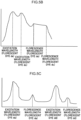
- a fluorescent dye da and a fluorescent dye db have excitation wavelength bands and fluorescence wavelength bands that are mutually adjacent to each other, there is interference between the fluorescence wavelengths of the fluorescent dye da and the excitation wavelengths of the fluorescent dye db. This might accordingly make detection of the fluorescence wavelengths of the fluorescent dye da difficult.
- the two fluorescent dyes employed in the aquifer layers 12A, 12B isolated from each other by the impermeable layer 16 are preferably selected such that there is sufficient separation between their respective excitation wavelength bands and fluorescence wavelength bands, such with the fluorescent dyes da, dd illustrated in Fig. 5C .
- the two fluorescent dyes employed in the aquifer layers 12A, 12B isolated from each other by the impermeable layer 16 are preferably selected such that there is sufficient separation between their respective excitation wavelength bands and fluorescence wavelength bands, such with the fluorescent dyes da, dd illustrated in Fig. 5C .
- interference patterns are not limited thereto.
- the fluorescence wavelengths of the fluorescent dye da is also sometimes affected so as to become difficult to detect.
- the same fluorescent dye may be employed as the marker for the purification agents to purify the aquifer layers 12A, 12B when the impermeable layer 16 illustrated in Fig. 4B is sufficiently thick, not cracked, etc. There is a low possibility of the fluorescent dye mixing in such cases even when the same fluorescent dye is employed therefor.
- exemplary embodiments of the present disclosure are not limited thereto.
- frozen earth, concrete, a cement-improved body, or the like may be employed therefor.
- the water-shielding wall 28 does not necessarily need to be provided.
- the water injection wells 24 are preferably disposed on an upstream side of a groundwater flow, and the water pumping wells 22 are preferably installed on the downstream side thereof. This enables injection liquid that has been injected into the subsurface ground 10 from the water injection wells 24 to be made to permeate smoothly into the subsurface ground 10.
- water quality improvement is performed in the first to the fifth examples by air being feed into the groundwater with the water treatment/warming device 32 illustrated in Fig. 1A and Fig. 1B
- the present invention is not limited thereto.
- a method to perform water quality improvement by adding a purification agent to the groundwater to cause a reaction or a method designed to separate contaminants from the groundwater by adsorption of the contaminants contained in the groundwater, may be employed as methods to perform water quality improvement.
- Nutrient salts and oxygen may be mixed in, or fresh decomposer microorganism may be mixed in, as the purification agent in cases in which groundwater is purified by employing a decomposer microorganism to biodegrade a contaminant.
- a flocculant may be mixed in to achieve smooth injection of the injection liquid using the water injection wells 24.
- the groundwater purified in the water treatment/warming device 32 is warmed by a heater in the first to the fifth example, the present invention not limited thereto.
- the groundwater may be warmed by causing heat exchange to take place between a heating medium in an air conditioner unit (not illustrated in the drawings) and the groundwater purified in the water treatment/warming device 32.
- waste heat, steam or the like from a building on or in the vicinity of the contaminated ground E may be utilized for warming. Note that warming might not always be needed in cases such as those in which the decomposer microorganisms are already active at a predetermined activity level.
- the ground injection agent concentration estimation system may be applied to a ground improvement system to counter liquefaction of the subsurface ground 10.
- a supercooled aqueous solution, air bubble infused water, a solidification agent, or the like may be employed as the injection agent, and similarly to in the contaminated ground purification system 20, a fluorescent dye, halogen ion, radioisotope, or the like may be employed as the marker.
- the concentration of the injection agent may be estimated from temperature measurements of the groundwater instead of by using a marker.
- a supercooled aqueous solution is an aqueous solution such as erythritol, sodium acetate trihydrate, sodium acetate decahydrate, or the like for injection into the subsurface ground 10 in a super-cooled state. Crystals are then introduced or a shock is imparted thereto at the point in time when the concentration of the supercooled aqueous solution in the groundwater has reached a predetermined concentration, thereby inducing crystallization to occur. Ground improvement is thereby achieved by solidifying the subsurface ground 10.
- air bubble infused water is a liquid resulting from infusing water with fine bubbles (air bubbles having a diameter of 100 ⁇ m or less), microbubbles (air bubbles having a diameter of 1 to 100 ⁇ m), or ultrafine bubbles (air bubbles having a diameter of 1 ⁇ m or less).
- the air bubble infused water is then injected into the subsurface ground 10 so as to achieve a state in which the groundwater does not saturate the subsurface ground 10 and contains air bubbles at a predetermined concentration.
- the water pressure in pores between particles of the subsurface ground 10 is thereby suppressed from rising during an earthquake, enabling liquefaction to be made less liable to occur.
- a material that may be employed as the solidification agent may be: a liquid suspension type non-waterglass based solidification agent such as a clay/cement based (such as bentonite, cement, or the like), an ultrafine particle based (such as Highbrid Silica (registered trademark)), or a special slag based (such as SILACSOL (registered trademark)- UF or the like) non-waterglass based solidification agent; a liquid suspension type waterglass based solidification agent such as an alkali (RMG-S5 or the like) or a neutral/acidic (Creanfarm or the like) liquid suspension type waterglass based solidification agent; a waterglass based liquid type inorganic solidification agent such as an alkali (ALSELICA (registered trademark) or the like), a neutral/acidic (HARDLIZER (registered trademark) or the like), a special neutral/acidic (Ecoryon(registered trademark) or the like), a special silica
- the ground injection agent concentration estimation system may be applied to a heat storage system utilizing heat in the ground of the subsurface ground 10.
- a heat storage material such as a supercooled aqueous solution is employed as the injection agent, and similarly to in the contaminated ground purification system 20, a fluorescent dye, halogen ion, radioisotope, or the like is employed as the marker.
- erythritol, sodium acetate trihydrate, sodium acetate decahydrate, or the like have a relatively large heat capacity when employed as a supercooled aqueous solution, in comparison to water or concrete, and accordingly readily exhibit the functionality of a heat storage material.
- the ground injection agent concentration estimation system may be applied as a water shielding system to reduce the groundwater level when excavating the subsurface ground 10.
- a supercooled aqueous solution or a solidification agent is employed as the injection agent, and similarly to in the contaminated ground purification system 20, a fluorescent dye, halogen ion, radioisotope, or the like is employed as the marker.
- the concentration of the injection agent may be estimated by measuring the temperature of the groundwater instead of by employing a marker.
Landscapes
- Life Sciences & Earth Sciences (AREA)
- Engineering & Computer Science (AREA)
- Health & Medical Sciences (AREA)
- Environmental & Geological Engineering (AREA)
- General Health & Medical Sciences (AREA)
- Soil Sciences (AREA)
- Chemical & Material Sciences (AREA)
- General Physics & Mathematics (AREA)
- Physics & Mathematics (AREA)
- Analytical Chemistry (AREA)
- Biochemistry (AREA)
- Immunology (AREA)
- Pathology (AREA)
- Nuclear Medicine, Radiotherapy & Molecular Imaging (AREA)
- Biomedical Technology (AREA)
- Mycology (AREA)
- Molecular Biology (AREA)
- Microbiology (AREA)
- Biotechnology (AREA)
- Remote Sensing (AREA)
- General Life Sciences & Earth Sciences (AREA)
- Water Supply & Treatment (AREA)
- Hydrology & Water Resources (AREA)
- Geology (AREA)
- Food Science & Technology (AREA)
- Medicinal Chemistry (AREA)
- Processing Of Solid Wastes (AREA)
- Investigating, Analyzing Materials By Fluorescence Or Luminescence (AREA)
- Investigating Or Analysing Materials By The Use Of Chemical Reactions (AREA)
Description
- The present disclosure relates to a ground injection agent concentration estimation method.
- In a soil purification method disclosed in Japanese Patent Application Laid-Open (
JP-A) No. 2005-305282
CN105973759 discloses another example of a method for in-situ injection and remediation of contaminated soil and groundwater where a tracer is injected together with an injection agent. -
JP-A No. 2005-305282 - In consideration of the above circumstances, an object of the present invention is to provide a ground injection agent concentration estimation method enabling a concentration of injection agent injected into ground to be estimated.
- The present invention provides therefore a ground injection agent concentration estimation method comprising: injecting an injection liquid comprising an injection agent comprising a purification agent to decompose a contaminant and an activator to activate bio-decomposition by the purification agent and markers comprising a first marker and a second different type of marker into the ground through a water injection well, wherein the first marker is characterized by exhibiting similar behavior to the purification agent in ground, and the second different type of marker is characterized by exhibiting similar behavior to the activator in ground and wherein the markers comprise one or more fluorescent dyes; measuring a concentration of the markers in groundwater at a location spaced apart from the water injection well; and estimating a concentration of the injection agent in the groundwater from the concentration of the markers. Preferred embodiments of the invention are set forth in the dependent claims.
- When an injection agent is injected into ground for the objective of contaminant purification, ground improvement, heat storage, water blocking, or the like, the concentration of the injection agent in groundwater needs to be appropriately managed in order to make the injection agent function effectively. However, sometimes sampled groundwater needs to be brought to a test laboratory and measured with bulky facilities in order to directly measure the concentration of the injection agent, and this takes effort to perform. Moreover, there is an issue in that sometimes measuring low concentrations of injection agent are difficult, or even though measurements are possible, it is difficult to discern whether or not the injection agent has arrived due to the injection agent dissolving and dispersing.
- In the ground injection agent concentration estimation method of the present invention, the injection agent comprises a purification agent to decompose a contaminant and an activator to activate bio-decomposition by the purification agent and markers comprising a first and a second different type or marker wherein the first marker has similar behavior to the purification agent in ground and the second different type of marker has similar behavior to the activator in the ground.
- The ground injection agent concentration estimation method of the present invention is able to purify the ground due to the purification agent and the activator being added to the injection liquid. The concentration of the purification agent and the activator in the groundwater of the ground needs to be appropriately managed in order to effectively decompose the contaminant in the ground. However, sometimes sampled groundwater needs to be brought to a test laboratory and measured with bulky facilities in order to directly measure the concentration of the purification agent or the activator, and this takes effort to perform.
- In the ground injection agent concentration estimation method of the present invention, the concentration of the markers in the groundwater is measured at a location spaced apart from the water injection well. The first marker exhibits similar behavior in the ground to that of the purification agent and the second marker exhibits similar behavior in the ground to that of the activator, and this accordingly enables the concentration of the purification agent and of the activator to be estimated from the concentration of the marker.
- The concentration of the purification agent and of the activator in the groundwater of the ground can accordingly be found. The contaminant can accordingly be effectively decomposed by appropriately managing the concentration of the purification agent and the activator in the groundwater of the ground.
- In the ground injection agent concentration estimation method of the present invention the markers comprise one or more fluorescent dyes.
- In the ground injection agent concentration estimation method of the present invention, the concentration of the purification agent and of the activator is estimated from the concentration of the fluorescent dyes in the groundwater at the location spaced apart from the water injection well. The concentration of the fluorescent dyes can be measured quantitatively as light intensity using a fluorescence measurement instrument. This enables a certain degree of precision to be guaranteed.
- In the ground injection agent concentration estimation of the present invention, the purification agent and the activator are injected into the ground through the water injection well, and the markers include one marker exhibiting similar behavior to the purification agent, and another different type of marker exhibiting similar behavior to the activator.
- In the ground injection agent concentration estimation method of the present invention, the purification agent and the activator are injected into the ground. Different types of marker are then respectively employed for the purification agent and the activator. This accordingly enables the concentration of the purification agent and the activator to be estimated from these respective concentrations.
- Thus even in cases in which the purification agent and the activator are mixed when injected into the ground, the respective concentrations thereof in the groundwater of the ground are able to be accurately estimated.
- The ground injection agent concentration estimation method according to the present invention enables the estimation of a concentration of an injection agent injected into ground.
-
-
Fig. 1A is a plan view illustrating a schematic configuration of an example of a ground injection agent concentration estimation system suitable for carrying out the method according to the present invention. -
Fig. 1B is a vertical cross-section illustrating a schematic configuration of a ground injection agent concentration estimation system according to said example.Fig. 2 is a vertical cross-section illustrating a relationship between an observation well and a measurement position in the ground injection agent concentration estimation system according to said example. -
Fig. 3 is a graph illustrating relationships against wavelength for excitation light and fluorescence intensity in a measurement device in the ground injection agent concentration estimation system according to said example. -
Fig. 4A is a plan view illustrating a modified example of purifying contaminated ground in double-layer aquifer layers formed by being interrupted in the vertical direction by an impermeable layer in an example of a ground injection agent concentration estimation system suitable for carrying out the method according to the present invention. -
Fig. 4B is a vertical cross-section illustrating a modified example of purifying contaminated ground in double-layer aquifer layers formed by being interrupted in the vertical direction by an impermeable layer in an example of a ground injection agent concentration estimation system suitable for carrying out the method according to the present invention. -
Fig. 5A is a graph illustrating relationships against wavelength for excitation light and fluorescence intensity for two types of fluorescent dye having respective excitation wavelength bands and fluorescence wavelength bands that are adjacent to each other in a measurement device an example of in a ground injection agent concentration estimation system suitable for carrying out the method according to the present invention. -
Fig. 5B is a graph illustrating relationships against wavelength for excitation light and fluorescence intensity for two types of fluorescent dye having respective excitation wavelength bands and fluorescence wavelength bands the overlap with each other in a measurement device in a ground injection agent concentration estimation system according to said example. -
Fig. 5C is a graph illustrating relationships against wavelength for excitation light and fluorescence intensity for two types of fluorescent dye having respective excitation wavelength bands and fluorescence wavelength bands that are separated from each other in a measurement device in a ground injection agent concentration estimation system according to said example. - Explanation follows regarding exemplary embodiments of the present disclosure, with reference to the drawings. Note that explanation regarding common configuration elements represented by the same reference numerals in plural drawings is sometimes omitted.
- An example of a ground injection agent concentration estimation system suitable for carrying out the method according to the present invention is applied to a contaminated
ground purification system 20 illustrated inFig. 1A andFig. 1B for decomposing a contaminant contained insubsurface ground 10. The contaminatedground purification system 20 includeswater pumping wells 22,water injection wells 24,observation wells 26, and a water-shielding wall 28 constructed in thesubsurface ground 10, apurification unit 30 that is constructed above ground level GL and that circulates groundwater between thesubsurface ground 10, the water pumpingwells 22, and thewater injection wells 24, and ameasurement device 40 for analyzing groundwater sampled from theobservation wells 26. - The
subsurface ground 10 is ground below the ground level GL, and includes anaquifer layer 12 through which groundwater flows, and animpermeable layer 14 through which groundwater does not flow. A portion of thesubsurface ground 10 containing contaminant at a reference value or greater (for example a value set for each contaminant type) is referred to as contaminated ground E. The definition of "contaminant" includes organic substances such as tetrachloroethylene, trichloroethylene, cis-1,2-dichloroethylene, vinyl chloride monomers, benzene, and the like, inorganic compounds such as hexavalent chromium, cyan, and the like, and oils such as mineral oils like gasoline, diesel, and the like. - A groundwater level HL is indicated in
Fig. 1B by a dotted-dashed line, and the direction of a flow of groundwater through the subsurface ground is indicated by dashed arrows. Note that the flow of groundwater is a flow generated by injecting an injection liquid containing a purification agent or the like, described later, into thesubsurface ground 10 through thewater injection wells 24, and by also pumping groundwater from thewater pumping wells 22. - The
water pumping wells 22 are water pumping means for pumping groundwater from thesubsurface ground 10. Groundwater in theaquifer layer 12 may be drawn up by water pump P and fed to thepurification unit 30. Although the water pump P is illustrated inFig. 1A andFig. 1B as being installed outside the water pumping wells 22 (water pumping wells water pumping wells 22. However, the water pump P may be installed outside thewater pumping wells 22. Moreover, thewater pumping wells 22 are disposed between the contaminated ground E and the water-shieldingwall 28, and thewater pumping wells 22 are buried in thesubsurface ground 10 such that a depth of lower ends of thewater pumping wells 22 are at the depth of the contaminated ground E or deeper. - Although, for convenience, only the two
water pumping wells Fig. 1A , exemplary embodiments of the present disclosure are not limited thereto, and any appropriate number of thewater pumping wells 22 may be disposed, according to the size of the site and so on. - Note that the
water pumping wells 22 may be disposed in the contaminated ground E. Specific methods for pumping water using thewater pumping wells 22, and the profile, size, and the like of thewater pumping wells 22 are known, and so detailed explanation thereof is omitted. - The water injection wells 24 (
water injection wells purification unit 30 into thesubsurface ground 10. The injection liquid may be fed into thesubsurface ground 10 using pumps and the like, not illustrated in the drawings. Thewater injection wells 24 are wells disposed between the contaminated ground E and the water-shielding wall 28 (on the opposite side to thewater pumping wells 22 from the perspective of the contaminated ground E), and are buried in thesubsurface ground 10 such that a depth of lower ends of thewater injection wells 24 is at the depth of the contaminated ground E or deeper. - Although, for convenience, only the two
water injection wells Fig. 1A , exemplary embodiments of the present disclosure are not limited thereto, and any appropriate number of thewater injection wells 24 may be disposed, according to the size of the site and so on. - Note that the
water injection wells 24 may be disposed within the contaminated ground E. Specific methods for injecting the injection liquid using thewater injection wells 24, and the profile, size, and the like of thewater injection wells 24 are known, and so detailed explanation thereof is omitted. - The observation wells 26 (
observation wells subsurface ground 10 at positions where theobservation wells 26 are buried. This includes, for example, a groundwater level, an in-ground temperature, a concentration in the groundwater of a later described purification agent, activator, and marker, and a concentration of a contaminant in the groundwater. - Various sensors, not illustrated in the drawings, are installed in the
observation wells 26. The groundwater level, the in-ground temperature, the concentration and the like of the marker, purification agent and the activator in the groundwater as mentioned above are measured by these sensors, and measured values thereof are transmitted as electrical signals to acontroller 38 of thepurification unit 30. - Note that sensors are also installed inside the
water pumping wells 22 and thewater injection wells 24. Namely, the respectivewater pumping wells 22 andwater injection wells 24 also function as observation means. Signal lines connected to the respective sensors and to thecontroller 38 are omitted from illustration inFig. 1A andFig. 1B , in order to avoid increasing the complexity of the drawings. - Moreover, the non-illustrated water pump installed inside or outside the
observation wells 26 is able to take a sample of groundwater at a predetermined depth in theobservation wells 26, and to pump the sampled groundwater to themeasurement device 40 installed above ground. - The
observation wells 26 are buried at plural locations in thesubsurface ground 10 enclosed by the water-shieldingwall 28 and, for convenience, only the threeobservation wells Fig. 1A . However, exemplary embodiments of the present invention are not limited thereto, and any appropriate number of theobservation wells 26 may be disposed, according to the size of the site and so on. - The water-shielding
wall 28 is a water-shielding means made from steel poling plates (sheet pile) disposed in thesubsurface ground 10 so as to enclose the periphery of the contaminated ground E and block the flow of groundwater between the inside and the outside of the water-shieldingwall 28. Namely, the water-shieldingwall 28 is disposed so as to the flow of groundwater in thesubsurface ground 10 at the "outside" of the water-shieldingwall 28 and the flow of groundwater in thesubsurface ground 10 at the "inside" of the water-shieldingwall 28 do not affect one another. - As illustrated in
Fig. 1B , a lower end of the water-shieldingwall 28 is embedded in theimpermeable layer 14. The contaminated ground E is thus enclosed by the water-shieldingwall 28 and theimpermeable layer 14, suppressing the flow of contaminant out into thesubsurface ground 10 on the outside of the water-shieldingwall 28. - The
purification unit 30 is a device to purify the groundwater pumped from the water pumping wells by adding at least one of a purification agent and an activator, described later, to the groundwater, and returning the groundwater to thesubsurface ground 10. Thepurification unit 30 is configured including a water treatment/warming device 32, anaddition tank 36, and thecontroller 38. - The water treatment/
warming device 32 separates (and purges) volatile contaminants and oil from groundwater pumped from the water pumping wells. Moreover, the water treatment/warming device 32 warms the purified groundwater using a non-illustrated heater that is temperature-controlled by thecontroller 38, described later. Warming the groundwater using the water treatment/warming device 32 promotes reproduction of a decomposer microorganism that biodegrades contaminants in thesubsurface ground 10, enabling the activity of the decomposer microorganism to be increased. - The
addition tank 36 produces injection liquid by adding to the groundwater at least one out of the purification agent and the activator, and a marker. Specifically, at least one out of the purification agent and activator, and the marker, are added to the groundwater inside theaddition tank 36 from a feeder (not illustrated in the drawings) controlled by thecontroller 38, described later. This is then agitated to produce the injection liquid for injecting into thesubsurface ground 10 through thewater injection wells 24. - Note that an injection agent according to the present invention comprises a purification and activator. The "purification agent" is a substance that decomposes the contaminant in the
subsurface ground 10, and is, for example, a "decomposer microorganism" such as dehalococcoides, dehalosulphide, or the like for biodegrading the contaminant, or a "chemical decomposer" for chemically decomposing the contaminant. Specific examples of such a chemical decomposer include "reducing agents" such as an iron-based slurry or "oxidizing agents" such as hydrogen peroxide, a persulfate, Fenton's reagent, a permanganate, a percarbonate, or the like. - Note that in said examplea decomposer microorganism (dehalococcoides) is employed as the purification agent. Moreover in the
addition tank 36, an activator is also added in addition to the purification agent, and detailed exemplary embodiments thereof are described below. - The "marker" is a substance exhibiting similar behavior in the subsurface ground 10 (including the contaminated ground E) to that of the purification agent or the activator, described later. The "marker" is also a substance whose concentration is easily measured in-situ (such as, for example, inside a building on or in the vicinity of the contaminated ground E) without employing bulky facilities, even when in a low concentration state. Examples thereof include a fluorescent dye, a halogen ion, a radioisotope, or the like. From among these, uranine, eosin, rhodamine B, rhodamine WT, pyranine, amino G acid, sodium naphthionate, sulforhodamine G, or the like may be employed as a fluorescent dye. A fluorescent dye (eosin) is employed in the first exemplary embodiment.
- Reference here to "exhibiting similar behavior ...to that of the purification agent or the activator" specifically means that the density, viscosity, adsorption/desorption characteristics, and the like of the marker with respect to the groundwater are about the same as those of the purification agent or the activator.
- Moreover, "about the same as" includes cases in which there is a complete match, and cases in which a slight difference arises that is measurable in tests.
- This means that the marker may be employed as a substance (tracer) to measure the concentration of the purification agent or the activator in the groundwater of the
subsurface ground 10. The concentration of the purification agent or the activator in the groundwater of thesubsurface ground 10 can be estimated by measuring the concentration of the marker. - Note that although in the present example the injection liquid is produced by adding the marker to the groundwater in the
addition tank 36, the concentration of the purification agent or the activator in the groundwater of thesubsurface ground 10 can be estimated without employing the marker. - In such cases, outside the scope of the present invention, the temperature of the groundwater is measured. Namely, the injection liquid warmed in the water treatment/
warming device 32 mixes with the groundwater of thesubsurface ground 10 and raises the temperature thereof. The purification agent or the activator can accordingly be determined to have reached the location where the temperature is measured when the temperature of the groundwater becomes higher than before the start of injection of the injection liquid. Furthermore, the concentration of the purification agent or activator in the groundwater of thesubsurface ground 10 can be estimated by measuring the change in this temperature. - Note that in temperature measurement the temperature of the groundwater does not necessarily always need to be measured in the observation well, and the temperature of the
subsurface ground 10 may, for example, be measured by a thermocouple buried in thesubsurface ground 10. Such a method to estimate the concentration of injection agent from the temperature of thesubsurface ground 10 or the groundwater without employing the marker may also be applied but falls outside the scope of the present invention. -
Fig. 2 illustrates a vertical cross-section to explain a relationship between theobservation wells 26 and themeasurement device 40. Themeasurement device 40 is configured including aheader 42 and afluorescence measurement instrument 44. - The groundwater inside the
observation wells fluorescence measurement instrument 44 through theheader 42 of themeasurement device 40. - The
header 42 is a consolidation pipe member to consolidate plural pipes into a single pipe. Opening or closing non-illustrated solenoid valves or valves therein enables selection of whichever groundwater is to be fed to thefluorescence measurement instrument 44 from out of the groundwater pumped from each of theobservation wells - The
fluorescence measurement instrument 44 is able to measure the intensity of light emitted from the fluorescent dye serving as the marker contained in the groundwater that has been fed in from theheader 42. More specifically, a light intensity C of fluorescence emitted by the fluorescent dye contained in the groundwater when excitation light has been illuminated from a light source device onto the groundwater can be measured.Fig. 3 illustrates a specific example of light intensities for the wavelengths of the excitation light and the wavelengths of the fluorescence. - The concentration of the fluorescent dye can be computed from the light intensity C. When the fluorescent dye concentration is expressed as a function of light intensity C, i.e. as F(C) (mg/l), then an estimated concentration X (mg/l) of the purification agent (decomposer microorganism) can be expressed in the following manner.

- The coefficient α is found from differences in adsorption/desorption characteristics measured by performing adsorption/desorption tests with the purification agent (decomposer microorganism) and the fluorescent dye. Note that although the adsorption/desorption characteristics of the marker with respect to the groundwater are, as stated above, about the same as those of the purification agent, there may be an amount of difference therebetween for which the coefficient α can be computed in this manner.
- The
controller 38 receives, as electric signals, information regarding the groundwater level, the in-ground temperature, the concentration and the like of the purification agent or activator in the groundwater, and so on measured by the sensors respectively installed in theobservation wells 26, thewater injection wells 24, and thewater pumping wells 22. Thecontroller 38 controls driving of the water treatment/warming device 32, theaddition tank 36, and the water pumps P according to the received information. - In the ground injection agent concentration estimation system of the first exemplary embodiment, as illustrated in
Fig. 2 , first in theaddition tank 36, the decomposer microorganism (dehalococcoides) serving as the purification agent, and the fluorescent dye (eosin) serving as the marker, are added to the injection liquid for injection into thesubsurface ground 10 through thewater injection wells 24. The concentration of the decomposer microorganism in the injection liquid and the fluorescent dye concentration in the injection liquid are made the same as each other in this case. Namely, the relationship between the respective concentrations in the injection liquid is expressed in the following manner.
- Next, the injection liquid, to which the decomposer microorganism (dehalococcoides) and the fluorescent dye (eosin) have been added, is injected from the
addition tank 36 into thewater injection wells 24. The injection liquid injected into thewater injection wells 24 disperses from thewater injection wells 24 into thesubsurface ground 10 and the contaminated ground E at a target speed by generating a water gradient in the groundwater using the water pump P illustrated inFig. 1A andFig. 1B to pump groundwater from thewater pumping wells 22. - When this is performed, due to the decomposer microorganism (dehalococcoides) and the fluorescent dye (eosin) having densities, viscosities, adsorption/desorption characteristics, and the like with respect to the groundwater that are about the same as those of the purification agent or the activator, the speeds of dispersing are about the same as each other, as respectively illustrated by S and T in
Fig. 2 . - However, the decomposer microorganism (dehalococcoides) and the fluorescent dye (eosin) have slightly different adsorption/desorption characteristics, and so differences arise in the concentration in the groundwater in the process of dispersing in the
subsurface ground 10. The relationship between the respective concentrations in the groundwater is accordingly estimated in the following manner by employing the coefficient α that accords with the adsorption/desorption characteristics.
- Next, the water pumps (not illustrated in the drawings) provided inside the
observation wells water injection wells 24 as illustrated inFig. 2 , take samples of groundwater inside theobservation wells fluorescence measurement instrument 44. The light intensity C of the fluorescent dye (eosin) is measured by the fluorescence measurement instrument, and the fluorescent dye (eosin) concentration F(C) (g/l) is computed therefrom. - Substituting the estimated decomposer microorganism concentration X (g/l) and the fluorescent dye (eosin) concentration F(C) (g/l) for the left side of Equation (1-2) yields the following expressions.

- The Equation (1) above is obtained by modifying Equation (1-3), and the decomposer microorganism concentration is computed therefrom.
- Note that although in the present exemplary embodiment the decomposer microorganism concentration in the injection liquid and the fluorescent dye concentration in the injection liquid are the same as each other, exemplary embodiments of the present disclosure are not limited thereto. For example, when the ratio between the decomposer microorganism concentration in the injection liquid and the fluorescent dye concentration in the injection liquid is (a: 1), then the estimated decomposer microorganism concentration is computed by multiplying the right hand side of Equation (1) by a.
- The value of "a" may be freely selected, however, since a contaminant decomposing effect is not expected from the fluorescent dye, the fluorescent dye may be contained at an amount needed to compute the decomposer microorganism concentration, and may be set at a = 60, for example.
- When the injection liquid to which the decomposer microorganism has been added is diluted by the groundwater, the decomposer microorganism concentration in the groundwater becomes lower than a detection limit (of the order of 102 copies/ml) measureable using an ordinary measurement method (quantitative PCR method such as quantitative real-time PCR). This makes it difficult to measure the decomposer microorganism concentration in the groundwater in a diluted state.
- In contrast thereto, even when the fluorescent dye is diluted to a low concentration state in the groundwater, the light intensity can still be measured using the fluorescence measurement instrument. The fluorescent dye concentration can then be computed from the light intensity.
- Moreover, the decomposer microorganism having the densities, viscosities, adsorption/desorption characteristics, and the like with respect to the groundwater that are about the same as those of the fluorescent dye. The decomposer microorganism concentration can accordingly be estimated as long as the fluorescent dye concentration in the groundwater is known.
- The contaminant can accordingly be effectively decomposed by appropriately managing the decomposer microorganism concentration in the
subsurface ground 10 and the groundwater of the contaminated ground E. - Although in the first example a fluorescent dye (eosin) is employed as the marker, a halogen ion is employed as the marker in a second example. In such cases, the estimated purification agent (decomposer microorganism) concentration X (copies/ml) can be expressed in terms of a concentration G(D) (mg/l) of the marker (halogen ion) in the following manner. Note that the concentration G(D) (mg/l) of the marker (halogen ion) is a function of the electrical conductivity D (S/m) measured using an electrical conductivity meter instead of the
fluorescence measurement instrument 44.
- The coefficient β is, similarly to the coefficient α in Equation (1) of the first exemplary embodiment, found from differences in adsorption/desorption characteristics found by performing adsorption/desorption tests for the purification agent (decomposer microorganism) and the marker (halogen ion).
- Note that the concentration G(D) (mg/l) of the halogen ion serving as the marker may be computed as an ion concentration (mol/l) measured using an ion meter instead of an electrical conductivity meter.
- Furthermore, as well as a halogen ion, a radioisotope may also be employed as the marker. In such cases, the marker concentration G(D) (mg/l) in Equation (2) is computed from an amount of radiation (Bq) measured using a radiation measurement instrument.
- Although in the first and second examples it is a "purification agent" that is added to the injection liquid in the
addition tank 36, in a third example outside the scope of the present invention an "activator" is added instead of the "purification agent". - The "activator" is a substance that stimulates bio-decomposition by a decomposer microorganism, and a hydrogen releasing agent, an organic substance, a pH adjuster, micronutrients, trace elements, or the like may be employed as the activator.
- Examples of organic substances that may be employed therefor include formic acid, acetic acid, propionic acid, butyric acid, lactic acid, or citric acid, sodium salts, potassium salts, or calcium salts thereof, glucose, fructose, galactose, lactose, maltose, trehalose, peptone, triptone, yeast extract, humic acid, plant oils, and the like.
- Examples of pH adjusters that may be employed include sodium or potassium carbonates or bicarbonates such as sodium bicarbonate, sodium carbonate, and the like, ammonium hydroxide, ammonium carbonate, sodium tripolyphosphate, sodium diphosphate, sodium triphosphate, and the like.
- Examples of micronutrients that may be employed include vitamin B12, vitamin B1, pantothenic acid, biotin, folate, and the like.
- Examples of trace elements that may be employed include Co, Zn, Fe, Mg, Ni, Mo, B, and the like.
- Due to these activators also having about the same densities, viscosities, adsorption/desorption characteristics, and the like with respect to groundwater as those of the marker, similarly to with the purification agent in the first exemplary embodiment, the concentration of the activator can be estimated using the marker.
- In the present exemplary embodiment a yeast extract is employed as the activator, and a fluorescent dye (eosin) is employed as the marker. The estimated activator (yeast extract) concentration Y (mg/l) can be expressed in terms of the fluorescent dye concentration F(C) (mg/l) in the following manner.

- Although a fluorescent dye is employed as the marker in said third example , a halogen ion is employed as the marker in a fourth example . In such cases, the estimated activator (yeast extract) concentration Y (mg/l) can be expressed in the following manner using a concentration X(D) (mg/l) of the marker (halogen ion). Note that as well as halogen ions, a radioisotope may also be employed as the marker.

- Although in the first to the fourth examples, one type of "purification agent" or "activator" is added as the "marker" to the injection liquid in the
addition tank 36, both "purification agent" and "activator" are added as the "marker" in a fifth example. - More specifically, a decomposer microorganism (dehalococcoides) and a chemical decomposer (hydrogen peroxide) are employed as the purification agent, and a yeast extract is employed as the activator. Moreover, a halogen ion is employed as the marker for the decomposer microorganism, a radioisotope is employed as the marker for the chemical decomposer, and a fluorescent dye is employed as the marker for the activator (yeast extract).
- The concentration of the decomposer microorganism (dehalococcoides) and the chemical decomposer (hydrogen peroxide) serving as the purification agent are both estimated using Equation (2). However, the coefficient β in Equation (2) is replaced as appropriate according to the respective adsorption/desorption characteristics of the decomposer microorganism (dehalococcoides), the chemical decomposer (hydrogen peroxide), the halogen ion, and the radioisotope. Moreover, the concentration of the activator (yeast extract) is estimated using Equation (3).
- In the fifth example, the respective concentrations of the decomposer microorganism, the chemical decomposer, and the activator can be estimated by measuring the concentration of the halogen ion, the amount of radiation of the radioisotope, and the light intensity of the fluorescent dye in the groundwater sampled from the
observation wells 26. - Thus in cases in which the contaminated ground E is contaminated by a contaminant such as tetrachloroethylene and a contaminant such as hexavalent chromium, effective decomposition of the contaminant can be achieved by appropriately managing the respective concentrations of the "decomposer microorganism" and the "chemical decomposer" employed as the purification agents appropriate for the respective contaminant, and by appropriately managing the concentration of the "activator" employed to raise the activity of the decomposer microorganism.
- Moreover, plural fluorescent dyes may be employed alone as the marker without employing a halogen ion or a radioisotope.
- For example, a yeast extract and a hydrogen releasing agent (polylactate ester) are added as activators to the injection liquid, and different types of fluorescent dye (eosin and uranine) are employed as respective markers therefor.
- This thereby enables the respective concentrations of the yeast extract and the hydrogen releasing agent (polylactate ester) to be estimated. Moreover, employing only the fluorescent dyes as markers eliminates the need to use an electrical conductivity meter or a radiation measurement instrument, enabling the concentration of the plural types of activator to be estimated using the fluorescence measurement instrument alone.
- Combinations of the above examples may also be employed. For example, the fifth example in which both "purification agents" and an "activator" and "markers" are added, may be combined with the other examplein which different types of fluorescent dye are employed as markers. In such cases, the injection liquid may, for example, have a decomposer microorganism added as a purification agent, a yeast extract added as an activator, a fluorescent dye (uranine) added as a marker for the decomposer microorganism, and a fluorescent dye (eosin) added as a marker for the yeast extract.
- Namely, purification agents, activators, and markers may be combined freely, and various combinations may be employed. These combinations include one type of purification agent together with one type of marker, plural types of purification agent together with plural types of marker, one type of activator together with one type of marker, plural types of activator together with plural types of marker, one type of purification agent and one type of activator together with two types of marker, plural types of purification agent and plural types of activator together with plural types of marker, etc. However, a reducing agent (for example, an iron-based slurry) serving as a purification agent is preferably not employed in combination with an activator.
- Explanation follows regarding various modified examples of the ground injection agent concentration estimation system suitable for carrying out the method according to the present invention. For example, although in the first to the fifth examples, as illustrated in
Fig. 1B , the contaminated ground E in the "single-layer"aquifer layer 12 formed above theimpermeable layer 14 is purified, the present inventions is not limited thereto. For example, as illustrated inFig. 4B , the contaminated ground E1, E2 in "double-layer" aquifer layers 12A, 12B, formed by theaquifer layer 12 being interrupted in the vertical direction by animpermeable layer 16, may be purified. Alternatively a "multilayer" aquifer layer of three or more layers may also be purified. - When purifying the contaminated ground E1, E2 of the "double-layer" aquifer layers 12A, 12B, in addition to water pumping wells 22 (
water pumping wells water injection wells observation wells lower aquifer layer 12B, water pumping wells 62 (water pumping wells water injection wells observation wells upper aquifer layer 12A. - Then, as illustrated in
Fig. 4A , in addition to apurification unit 30 for circulating groundwater between theaquifer layer 12B, thewater pumping wells 22, and thewater injection wells 24, apurification unit 50 is also provided for circulating groundwater between theaquifer layer 12A, thewater pumping wells 62, and thewater injection wells 64. This approach enables purification of the twoaquifer layers impermeable layer 16. Similarly to thepurification unit 30, thepurification unit 50 also includes a water treatment/warming device 52, anaddition tank 56, and acontroller 58. Note that thecontroller 38 of thepurification unit 30 and thecontroller 58 of thepurification unit 50 may be consolidated into a single unit. - However, in cases in which fluorescent dyes are employed as markers for the purification agents purifying the aquifer layers 12A, 12B, there is a possibility of a fluorescent dye flowing from the
aquifer layer 12A to theaquifer layer 12B through portions where the thickness of theimpermeable layer 16 is thin or there are cracks therein, resulting in two fluorescent dyes mixing in theaquifer layer 12B. There is also the possibility of a fluorescent dye flowing from theaquifer layer 12B to theaquifer layer 12A such that two fluorescent dyes mix in theaquifer layer 12A. - For example, as illustrated in
Fig. 5A , when a fluorescent dye da and a fluorescent dye db have excitation wavelength bands and fluorescence wavelength bands that are mutually adjacent to each other, there is interference between the fluorescence wavelengths of the fluorescent dye da and the excitation wavelengths of the fluorescent dye db. This might accordingly make detection of the fluorescence wavelengths of the fluorescent dye da difficult. - Moreover, as illustrated in
Fig. 5B , when the fluorescent dye da and a fluorescent dye dc that have excitation wavelength bands and fluorescence wavelength bands that overlap with each other are mixed together, there is interference between the fluorescence wavelengths of the fluorescent dye da and the excitation wavelengths of the fluorescent dye dc. Moreover, there is also interference between the fluorescence wavelengths of the fluorescent dye da and the fluorescence wavelengths of the fluorescent dye dc. This might accordingly make detection of the fluorescence wavelengths of the fluorescent dye da and the fluorescence wavelengths of the fluorescent dye dc difficult. - Thus in order to suppress interference between light such as that of the examples illustrated in
Fig. 5A andFig. 5B , the two fluorescent dyes employed in the aquifer layers 12A, 12B isolated from each other by theimpermeable layer 16 are preferably selected such that there is sufficient separation between their respective excitation wavelength bands and fluorescence wavelength bands, such with the fluorescent dyes da, dd illustrated inFig. 5C . Note that although examples illustrated inFig. 5A andFig. 5B show light interference that makes detection of the fluorescence wavelengths of the fluorescent dye da difficult, interference patterns are not limited thereto. For example, when there is interference between the excitation wavelengths of the fluorescent dye da and the fluorescence wavelengths or the excitation wavelength of a different fluorescent dye, then the fluorescence wavelengths of the fluorescent dye da is also sometimes affected so as to become difficult to detect. - Note that the same fluorescent dye may be employed as the marker for the purification agents to purify the aquifer layers 12A, 12B when the
impermeable layer 16 illustrated inFig. 4B is sufficiently thick, not cracked, etc. There is a low possibility of the fluorescent dye mixing in such cases even when the same fluorescent dye is employed therefor. - Moreover, although steel poling plates (sheet pile) is employed as the material of the water-shielding
wall 28 illustrated inFig. 1A andFig. 1B in the first to the fifth exemplary embodiments, exemplary embodiments of the present disclosure are not limited thereto. For example, frozen earth, concrete, a cement-improved body, or the like may be employed therefor. Moreover, the water-shieldingwall 28 does not necessarily need to be provided. In cases in which the water-shieldingwall 28 is not provided, thewater injection wells 24 are preferably disposed on an upstream side of a groundwater flow, and thewater pumping wells 22 are preferably installed on the downstream side thereof. This enables injection liquid that has been injected into thesubsurface ground 10 from thewater injection wells 24 to be made to permeate smoothly into thesubsurface ground 10. - Although water quality improvement is performed in the first to the fifth examples by air being feed into the groundwater with the water treatment/
warming device 32 illustrated inFig. 1A andFig. 1B , the present invention is not limited thereto. For example, a method to perform water quality improvement by adding a purification agent to the groundwater to cause a reaction, or a method designed to separate contaminants from the groundwater by adsorption of the contaminants contained in the groundwater, may be employed as methods to perform water quality improvement. - Nutrient salts and oxygen may be mixed in, or fresh decomposer microorganism may be mixed in, as the purification agent in cases in which groundwater is purified by employing a decomposer microorganism to biodegrade a contaminant. Moreover, a flocculant may be mixed in to achieve smooth injection of the injection liquid using the
water injection wells 24. - Although the groundwater purified in the water treatment/
warming device 32 is warmed by a heater in the first to the fifth example, the present invention not limited thereto. For example, the groundwater may be warmed by causing heat exchange to take place between a heating medium in an air conditioner unit (not illustrated in the drawings) and the groundwater purified in the water treatment/warming device 32. Furthermore, waste heat, steam or the like from a building on or in the vicinity of the contaminated ground E may be utilized for warming. Note that warming might not always be needed in cases such as those in which the decomposer microorganisms are already active at a predetermined activity level. - In an example outside to scope of the present invention, the ground injection agent concentration estimation system may be applied to a ground improvement system to counter liquefaction of the
subsurface ground 10. In such cases, a supercooled aqueous solution, air bubble infused water, a solidification agent, or the like may be employed as the injection agent, and similarly to in the contaminatedground purification system 20, a fluorescent dye, halogen ion, radioisotope, or the like may be employed as the marker. Alternatively, the concentration of the injection agent may be estimated from temperature measurements of the groundwater instead of by using a marker. - Note that a supercooled aqueous solution is an aqueous solution such as erythritol, sodium acetate trihydrate, sodium acetate decahydrate, or the like for injection into the
subsurface ground 10 in a super-cooled state. Crystals are then introduced or a shock is imparted thereto at the point in time when the concentration of the supercooled aqueous solution in the groundwater has reached a predetermined concentration, thereby inducing crystallization to occur. Ground improvement is thereby achieved by solidifying thesubsurface ground 10. - Moreover, air bubble infused water is a liquid resulting from infusing water with fine bubbles (air bubbles having a diameter of 100 µm or less), microbubbles (air bubbles having a diameter of 1 to 100 µm), or ultrafine bubbles (air bubbles having a diameter of 1 µm or less). The air bubble infused water is then injected into the
subsurface ground 10 so as to achieve a state in which the groundwater does not saturate thesubsurface ground 10 and contains air bubbles at a predetermined concentration. The water pressure in pores between particles of thesubsurface ground 10 is thereby suppressed from rising during an earthquake, enabling liquefaction to be made less liable to occur. - Moreover, a material that may be employed as the solidification agent may be: a liquid suspension type non-waterglass based solidification agent such as a clay/cement based (such as bentonite, cement, or the like), an ultrafine particle based (such as Highbrid Silica (registered trademark)), or a special slag based (such as SILACSOL (registered trademark)- UF or the like) non-waterglass based solidification agent; a liquid suspension type waterglass based solidification agent such as an alkali (RMG-S5 or the like) or a neutral/acidic (Creanfarm or the like) liquid suspension type waterglass based solidification agent; a waterglass based liquid type inorganic solidification agent such as an alkali (ALSELICA (registered trademark) or the like), a neutral/acidic (HARDLIZER (registered trademark) or the like), a special neutral/acidic (Ecoryon(registered trademark) or the like), a special silica (ECOSILICA (registered trademark) or the like) waterglass based liquid type inorganic solidification agent; or an alkali (RSG-3) waterglass based liquid organic solidification agent.
- Furthermore, the ground injection agent concentration estimation system may be applied to a heat storage system utilizing heat in the ground of the
subsurface ground 10. In such cases, a heat storage material such as a supercooled aqueous solution is employed as the injection agent, and similarly to in the contaminatedground purification system 20, a fluorescent dye, halogen ion, radioisotope, or the like is employed as the marker. - Note that erythritol, sodium acetate trihydrate, sodium acetate decahydrate, or the like have a relatively large heat capacity when employed as a supercooled aqueous solution, in comparison to water or concrete, and accordingly readily exhibit the functionality of a heat storage material.
- Furthermore, the ground injection agent concentration estimation system may be applied as a water shielding system to reduce the groundwater level when excavating the
subsurface ground 10. In such cases a supercooled aqueous solution or a solidification agent is employed as the injection agent, and similarly to in the contaminatedground purification system 20, a fluorescent dye, halogen ion, radioisotope, or the like is employed as the marker. Alternatively, the concentration of the injection agent may be estimated by measuring the temperature of the groundwater instead of by employing a marker.
Claims (4)
- A ground injection agent concentration estimation method comprising:injecting an injection liquid comprising an injection agent comprising a purification agent to decompose a contaminant and an activator to activate bio-decomposition by the purification agent and markers comprising a first marker and a second different type of marker into the ground through a water injection well (24), wherein the first marker is characterized by exhibiting similar behavior to the purification agent in ground, and the second different type of marker is characterized by exhibiting similar behavior to the activator in ground and wherein the markers comprise one or more fluorescent dyes;measuring a concentration of the markers in groundwater at a location spaced apart from the water injection well (24); andestimating a concentration of the injection agent in the groundwater from the concentration of the markers.
- The ground injection agent concentration estimation method of claim 1, wherein the one or more fluorescent dye is selected from the group consisting of uranine, eosin, rhodamine B, rhodamine WT, pyranine, amino G acid, sodium naphthionate, and sulforhodamine.
- The ground injection agent concentration estimation method of claim 1, wherein the injection agent and the markers exhibit similar density, viscosity, adsorption/desorption characteristics with respect to the groundwater.
- The ground injection agent concentration estimation method of claim 3, wherein the injection agent and the markers are both characterized by exhibiting a similar speed of dispersing into the ground.
Priority Applications (1)
| Application Number | Priority Date | Filing Date | Title |
|---|---|---|---|
| EP22183131.6A EP4108350B1 (en) | 2016-11-14 | 2017-08-29 | Ground injection agent concentration management method |
Applications Claiming Priority (2)
| Application Number | Priority Date | Filing Date | Title |
|---|---|---|---|
| JP2016221687 | 2016-11-14 | ||
| PCT/JP2017/031018 WO2018087996A1 (en) | 2016-11-14 | 2017-08-29 | System for estimating concentration of soil injection agent |
Related Child Applications (2)
| Application Number | Title | Priority Date | Filing Date |
|---|---|---|---|
| EP22183131.6A Division EP4108350B1 (en) | 2016-11-14 | 2017-08-29 | Ground injection agent concentration management method |
| EP22183131.6A Division-Into EP4108350B1 (en) | 2016-11-14 | 2017-08-29 | Ground injection agent concentration management method |
Publications (3)
| Publication Number | Publication Date |
|---|---|
| EP3540433A1 EP3540433A1 (en) | 2019-09-18 |
| EP3540433A4 EP3540433A4 (en) | 2020-08-19 |
| EP3540433B1 true EP3540433B1 (en) | 2023-10-04 |
Family
ID=62109211
Family Applications (2)
| Application Number | Title | Priority Date | Filing Date |
|---|---|---|---|
| EP17868770.3A Active EP3540433B1 (en) | 2016-11-14 | 2017-08-29 | Method for estimating concentration of soil injection agent |
| EP22183131.6A Active EP4108350B1 (en) | 2016-11-14 | 2017-08-29 | Ground injection agent concentration management method |
Family Applications After (1)
| Application Number | Title | Priority Date | Filing Date |
|---|---|---|---|
| EP22183131.6A Active EP4108350B1 (en) | 2016-11-14 | 2017-08-29 | Ground injection agent concentration management method |
Country Status (6)
| Country | Link |
|---|---|
| US (1) | US11231406B2 (en) |
| EP (2) | EP3540433B1 (en) |
| JP (1) | JP7136415B2 (en) |
| CN (1) | CN109983339B (en) |
| PL (2) | PL4108350T3 (en) |
| WO (1) | WO2018087996A1 (en) |
Families Citing this family (11)
| Publication number | Priority date | Publication date | Assignee | Title |
|---|---|---|---|---|
| CN107720853B (en) * | 2017-11-20 | 2021-04-16 | 中国环境科学研究院 | DNAPL pollution remediation system and method in groundwater based on pollution control |
| JP7036383B2 (en) * | 2018-11-29 | 2022-03-15 | 株式会社竹中工務店 | Soil purification method |
| JP6586503B6 (en) * | 2018-11-30 | 2019-12-11 | 株式会社エーバイシー | Fine bubble water replacement method and fine bubble water replacement device |
| JP7099670B2 (en) * | 2018-12-27 | 2022-07-12 | 株式会社竹中工務店 | Optical brightener fading system |
| JP7095840B2 (en) * | 2018-12-27 | 2022-07-05 | 株式会社竹中工務店 | Fluorescent dye concentration control system and fluorescent dye concentration control method |
| JP2020142175A (en) * | 2019-03-05 | 2020-09-10 | 栗田工業株式会社 | Soil and / or groundwater purification methods |
| CN110530762A (en) * | 2019-09-05 | 2019-12-03 | 陕西煤业化工技术研究院有限责任公司 | A kind of grouting and reinforcing liquid diffusion test device and method |
| JP7499081B2 (en) | 2020-06-19 | 2024-06-13 | 株式会社竹中工務店 | Method for estimating the concentration of injectable agent |
| JP7510793B2 (en) | 2020-06-19 | 2024-07-04 | 株式会社竹中工務店 | Method for estimating the concentration of injectable agent |
| CN114951242B (en) * | 2022-04-18 | 2023-01-10 | 生态环境部土壤与农业农村生态环境监管技术中心 | Multiphase extraction and tail gas purification device and application method for pollutants in heterogeneous soil |
| CN118444358B (en) * | 2024-05-11 | 2024-10-11 | 江苏省环境科学研究院 | A method for detecting cross contamination in soil sampling for site investigation based on 14C labeling |
Family Cites Families (27)
| Publication number | Priority date | Publication date | Assignee | Title |
|---|---|---|---|---|
| US4783314A (en) * | 1987-02-26 | 1988-11-08 | Nalco Chemical Company | Fluorescent tracers - chemical treatment monitors |
| US5120661A (en) * | 1987-12-11 | 1992-06-09 | Diversey Corporation | Method for detection and quantitative analysis for water treatment chemicals |
| DE4234466A1 (en) * | 1992-10-13 | 1994-04-14 | Henkel Kgaa | Method for determining the concentration of an active substance containing a tracer in active substance solutions |
| US5370478A (en) * | 1993-05-11 | 1994-12-06 | E. I. Du Pont De Nemours And Company | Process for isolating contaminated soil |
| US5411889A (en) * | 1994-02-14 | 1995-05-02 | Nalco Chemical Company | Regulating water treatment agent dosage based on operational system stresses |
| JPH07308690A (en) * | 1994-05-20 | 1995-11-28 | Canon Inc | Degradation material and method of implementation for in-situ microbial degradation |
| DE69606378T2 (en) * | 1995-11-09 | 2000-07-06 | Nalco Chemical Co., Naperville | Monitoring of microbiological activity in a fluid system |
| DE19722999A1 (en) * | 1997-06-02 | 1998-12-03 | Peter Dipl Biol Dr Harborth | Soil decontamination process |
| JPH1157731A (en) | 1997-08-15 | 1999-03-02 | Japan Organo Co Ltd | Water treatment and water treatment plant |
| JP3420949B2 (en) * | 1997-12-25 | 2003-06-30 | キヤノン株式会社 | Soil purification device and method for repairing contaminated soil |
| JP2000263033A (en) * | 1999-03-16 | 2000-09-26 | Aquas Corp | Method for controlling drug concentration in circulating water system |
| JP2002119951A (en) | 2000-10-13 | 2002-04-23 | Sumitomo Metal Mining Co Ltd | Soil and groundwater purification management system and purification management method |
| JP3808712B2 (en) | 2001-02-26 | 2006-08-16 | 鹿島建設株式会社 | Tracer test apparatus and single hole tracer test method |
| US7032662B2 (en) * | 2001-05-23 | 2006-04-25 | Core Laboratories Lp | Method for determining the extent of recovery of materials injected into oil wells or subsurface formations during oil and gas exploration and production |
| JP2004170085A (en) * | 2002-11-15 | 2004-06-17 | Kankyo Eng Co Ltd | Monitoring structure and monitoring method of soil after purification work of contaminated soil |
| JP2005305282A (en) | 2004-04-21 | 2005-11-04 | Hitachi Plant Eng & Constr Co Ltd | Soil purification method |
| JP2006275940A (en) | 2005-03-30 | 2006-10-12 | Hitachi Plant Technologies Ltd | Soil purification monitoring method |
| JP5023850B2 (en) * | 2007-07-05 | 2012-09-12 | パナソニック株式会社 | Method for purifying contaminated soil and groundwater |
| CN101424672A (en) | 2007-10-31 | 2009-05-06 | 中国石油化工股份有限公司 | Tracer and its use method |
| JP5184225B2 (en) | 2008-06-20 | 2013-04-17 | 株式会社竹中工務店 | How to remove pollutants |
| CN101726475A (en) * | 2008-10-31 | 2010-06-09 | 中国石油化工股份有限公司 | Fluorescent tracer for water treatment and using method thereof |
| JP2011173037A (en) | 2010-02-23 | 2011-09-08 | Sumitomo Metal Mining Co Ltd | Method for cleaning soil or underground water and method for confirming concentration of microbial nutritive composition |
| JP5952706B2 (en) * | 2012-10-15 | 2016-07-13 | 大成建設株式会社 | Tracer test method |
| JP6411716B2 (en) * | 2013-07-29 | 2018-10-24 | Dowaエコシステム株式会社 | Soil / groundwater purification method and soil / groundwater purification device |
| JP2016221687A (en) | 2015-05-27 | 2016-12-28 | 住友ゴム工業株式会社 | Manufacturing method of sheet material |
| JP5971606B1 (en) * | 2015-12-18 | 2016-08-17 | 強化土株式会社 | Soil purification method |
| CN105973759B (en) * | 2016-06-23 | 2018-06-05 | 北京建工环境修复股份有限公司 | Injection reparation dilation angle determines method in situ for a kind of contaminated soil and underground water |
-
2017
- 2017-08-29 PL PL22183131.6T patent/PL4108350T3/en unknown
- 2017-08-29 EP EP17868770.3A patent/EP3540433B1/en active Active
- 2017-08-29 JP JP2018550041A patent/JP7136415B2/en active Active
- 2017-08-29 WO PCT/JP2017/031018 patent/WO2018087996A1/en not_active Ceased
- 2017-08-29 US US16/348,755 patent/US11231406B2/en active Active
- 2017-08-29 CN CN201780069363.2A patent/CN109983339B/en active Active
- 2017-08-29 EP EP22183131.6A patent/EP4108350B1/en active Active
- 2017-08-29 PL PL17868770.3T patent/PL3540433T3/en unknown
Also Published As
| Publication number | Publication date |
|---|---|
| WO2018087996A1 (en) | 2018-05-17 |
| EP4108350A1 (en) | 2022-12-28 |
| JP7136415B2 (en) | 2022-09-13 |
| JPWO2018087996A1 (en) | 2019-09-26 |
| US11231406B2 (en) | 2022-01-25 |
| US20190324008A1 (en) | 2019-10-24 |
| CN109983339A (en) | 2019-07-05 |
| EP3540433A1 (en) | 2019-09-18 |
| PL3540433T3 (en) | 2024-01-03 |
| CN109983339B (en) | 2022-08-05 |
| EP3540433A4 (en) | 2020-08-19 |
| EP4108350B1 (en) | 2024-10-02 |
| PL4108350T3 (en) | 2024-12-16 |
Similar Documents
| Publication | Publication Date | Title |
|---|---|---|
| EP4108350B1 (en) | Ground injection agent concentration management method | |
| Gomez et al. | Biogeochemical changes during bio-cementation mediated by stimulated and augmented ureolytic microorganisms | |
| Pauwels et al. | Field tracer test for denitrification in a pyrite-bearing schist aquifer | |
| Borden et al. | Control of BTEX migration using a biologically enhanced permeable barrier | |
| Jahnke et al. | Advective pore water input of nutrients to the Satilla River Estuary, Georgia, USA | |
| US6268205B1 (en) | Subsurface decontamination method | |
| Patterson et al. | Fate of nine recycled water trace organic contaminants and metal (loid) s during managed aquifer recharge into a anaerobic aquifer: column studies | |
| Valhondo et al. | Evaluation of EOC removal processes during artificial recharge through a reactive barrier | |
| Brunsting et al. | In situ treatment of arsenic-contaminated groundwater by air sparging | |
| Wiesner et al. | Reduced permeability in groundwater remediation systems: Role of mobilized colloids and injected chemicals | |
| Zhao et al. | Oxidative precipitation of Fe (II) in porous media: Laboratory experiment and numerical simulation | |
| Klein | Sediment porewater exchange and solute release during ebullition | |
| Graffam et al. | Hydro-biogeochemical processes and nitrogen removal potential of a tidally influenced permeable reactive barrier behind a perforated marine bulkhead | |
| JP7095840B2 (en) | Fluorescent dye concentration control system and fluorescent dye concentration control method | |
| JP7499081B2 (en) | Method for estimating the concentration of injectable agent | |
| JP7510793B2 (en) | Method for estimating the concentration of injectable agent | |
| Hatton et al. | Field demonstration of polymer stabilized activated carbon for in situ treatment of per-and polyfluoroalkyl substances (PFAS)-impacted groundwater | |
| CN114632809B (en) | Risk control method for polluted site and in-situ risk control domain of polluted site | |
| Rust et al. | Laboratory sand column study of encapsulated buffer release for potential in situ pH control | |
| JP4680718B2 (en) | Optimization method for remediation of contaminated soil and permeation rate measuring device used therefor | |
| JP7099670B2 (en) | Optical brightener fading system | |
| JP6797090B2 (en) | Purification method | |
| Balcke et al. | Nitrogen as an indicator of mass transfer during in-situ gas sparging | |
| Levakov et al. | Quantification of in-situ remediation of deep unsaturated zone and groundwater | |
| Adams | Hydraulic response to emulsified vegetable oil biostimulation: in-situ test in a highly heterogenous uranium contaminated aquifer |
Legal Events
| Date | Code | Title | Description |
|---|---|---|---|
| STAA | Information on the status of an ep patent application or granted ep patent |
Free format text: STATUS: THE INTERNATIONAL PUBLICATION HAS BEEN MADE |
|
| PUAI | Public reference made under article 153(3) epc to a published international application that has entered the european phase |
Free format text: ORIGINAL CODE: 0009012 |
|
| STAA | Information on the status of an ep patent application or granted ep patent |
Free format text: STATUS: REQUEST FOR EXAMINATION WAS MADE |
|
| 17P | Request for examination filed |
Effective date: 20190605 |
|
| AK | Designated contracting states |
Kind code of ref document: A1 Designated state(s): AL AT BE BG CH CY CZ DE DK EE ES FI FR GB GR HR HU IE IS IT LI LT LU LV MC MK MT NL NO PL PT RO RS SE SI SK SM TR |
|
| AX | Request for extension of the european patent |
Extension state: BA ME |
|
| DAV | Request for validation of the european patent (deleted) | ||
| DAX | Request for extension of the european patent (deleted) | ||
| REG | Reference to a national code |
Ref country code: DE Ref legal event code: R079 Free format text: PREVIOUS MAIN CLASS: G01N0033240000 Ipc: B09C0001020000 Ref country code: DE Ref legal event code: R079 Ref document number: 602017075035 Country of ref document: DE Free format text: PREVIOUS MAIN CLASS: G01N0033240000 Ipc: B09C0001020000 |
|
| A4 | Supplementary search report drawn up and despatched |
Effective date: 20200720 |
|
| RIC1 | Information provided on ipc code assigned before grant |
Ipc: G01N 21/64 20060101ALI20200714BHEP Ipc: B09C 1/02 20060101AFI20200714BHEP Ipc: B09C 1/10 20060101ALI20200714BHEP Ipc: G01N 33/24 20060101ALI20200714BHEP Ipc: B09C 1/08 20060101ALI20200714BHEP |
|
| STAA | Information on the status of an ep patent application or granted ep patent |
Free format text: STATUS: EXAMINATION IS IN PROGRESS |
|
| 17Q | First examination report despatched |
Effective date: 20210326 |
|
| GRAP | Despatch of communication of intention to grant a patent |
Free format text: ORIGINAL CODE: EPIDOSNIGR1 |
|
| STAA | Information on the status of an ep patent application or granted ep patent |
Free format text: STATUS: GRANT OF PATENT IS INTENDED |
|
| INTG | Intention to grant announced |
Effective date: 20221201 |
|
| GRAJ | Information related to disapproval of communication of intention to grant by the applicant or resumption of examination proceedings by the epo deleted |
Free format text: ORIGINAL CODE: EPIDOSDIGR1 |
|
| STAA | Information on the status of an ep patent application or granted ep patent |
Free format text: STATUS: EXAMINATION IS IN PROGRESS |
|
| INTC | Intention to grant announced (deleted) | ||
| GRAP | Despatch of communication of intention to grant a patent |
Free format text: ORIGINAL CODE: EPIDOSNIGR1 |
|
| STAA | Information on the status of an ep patent application or granted ep patent |
Free format text: STATUS: GRANT OF PATENT IS INTENDED |
|
| INTG | Intention to grant announced |
Effective date: 20230425 |
|
| P01 | Opt-out of the competence of the unified patent court (upc) registered |
Effective date: 20230620 |
|
| GRAS | Grant fee paid |
Free format text: ORIGINAL CODE: EPIDOSNIGR3 |
|
| GRAA | (expected) grant |
Free format text: ORIGINAL CODE: 0009210 |
|
| STAA | Information on the status of an ep patent application or granted ep patent |
Free format text: STATUS: THE PATENT HAS BEEN GRANTED |
|
| AK | Designated contracting states |
Kind code of ref document: B1 Designated state(s): AL AT BE BG CH CY CZ DE DK EE ES FI FR GB GR HR HU IE IS IT LI LT LU LV MC MK MT NL NO PL PT RO RS SE SI SK SM TR |
|
| REG | Reference to a national code |
Ref country code: GB Ref legal event code: FG4D |
|
| REG | Reference to a national code |
Ref country code: CH Ref legal event code: EP |
|
| REG | Reference to a national code |
Ref country code: DE Ref legal event code: R096 Ref document number: 602017075035 Country of ref document: DE |
|
| REG | Reference to a national code |
Ref country code: IE Ref legal event code: FG4D |
|
| REG | Reference to a national code |
Ref country code: NL Ref legal event code: FP |
|
| REG | Reference to a national code |
Ref country code: LT Ref legal event code: MG9D |
|
| REG | Reference to a national code |
Ref country code: AT Ref legal event code: MK05 Ref document number: 1617210 Country of ref document: AT Kind code of ref document: T Effective date: 20231004 |
|
| PG25 | Lapsed in a contracting state [announced via postgrant information from national office to epo] |
Ref country code: GR Free format text: LAPSE BECAUSE OF FAILURE TO SUBMIT A TRANSLATION OF THE DESCRIPTION OR TO PAY THE FEE WITHIN THE PRESCRIBED TIME-LIMIT Effective date: 20240105 |
|
| PG25 | Lapsed in a contracting state [announced via postgrant information from national office to epo] |
Ref country code: IS Free format text: LAPSE BECAUSE OF FAILURE TO SUBMIT A TRANSLATION OF THE DESCRIPTION OR TO PAY THE FEE WITHIN THE PRESCRIBED TIME-LIMIT Effective date: 20240204 |
|
| PG25 | Lapsed in a contracting state [announced via postgrant information from national office to epo] |
Ref country code: LT Free format text: LAPSE BECAUSE OF FAILURE TO SUBMIT A TRANSLATION OF THE DESCRIPTION OR TO PAY THE FEE WITHIN THE PRESCRIBED TIME-LIMIT Effective date: 20231004 |
|
| PG25 | Lapsed in a contracting state [announced via postgrant information from national office to epo] |
Ref country code: AT Free format text: LAPSE BECAUSE OF FAILURE TO SUBMIT A TRANSLATION OF THE DESCRIPTION OR TO PAY THE FEE WITHIN THE PRESCRIBED TIME-LIMIT Effective date: 20231004 |
|
| PG25 | Lapsed in a contracting state [announced via postgrant information from national office to epo] |
Ref country code: ES Free format text: LAPSE BECAUSE OF FAILURE TO SUBMIT A TRANSLATION OF THE DESCRIPTION OR TO PAY THE FEE WITHIN THE PRESCRIBED TIME-LIMIT Effective date: 20231004 |
|
| PG25 | Lapsed in a contracting state [announced via postgrant information from national office to epo] |
Ref country code: LT Free format text: LAPSE BECAUSE OF FAILURE TO SUBMIT A TRANSLATION OF THE DESCRIPTION OR TO PAY THE FEE WITHIN THE PRESCRIBED TIME-LIMIT Effective date: 20231004 Ref country code: IS Free format text: LAPSE BECAUSE OF FAILURE TO SUBMIT A TRANSLATION OF THE DESCRIPTION OR TO PAY THE FEE WITHIN THE PRESCRIBED TIME-LIMIT Effective date: 20240204 Ref country code: GR Free format text: LAPSE BECAUSE OF FAILURE TO SUBMIT A TRANSLATION OF THE DESCRIPTION OR TO PAY THE FEE WITHIN THE PRESCRIBED TIME-LIMIT Effective date: 20240105 Ref country code: ES Free format text: LAPSE BECAUSE OF FAILURE TO SUBMIT A TRANSLATION OF THE DESCRIPTION OR TO PAY THE FEE WITHIN THE PRESCRIBED TIME-LIMIT Effective date: 20231004 Ref country code: BG Free format text: LAPSE BECAUSE OF FAILURE TO SUBMIT A TRANSLATION OF THE DESCRIPTION OR TO PAY THE FEE WITHIN THE PRESCRIBED TIME-LIMIT Effective date: 20240104 Ref country code: AT Free format text: LAPSE BECAUSE OF FAILURE TO SUBMIT A TRANSLATION OF THE DESCRIPTION OR TO PAY THE FEE WITHIN THE PRESCRIBED TIME-LIMIT Effective date: 20231004 Ref country code: PT Free format text: LAPSE BECAUSE OF FAILURE TO SUBMIT A TRANSLATION OF THE DESCRIPTION OR TO PAY THE FEE WITHIN THE PRESCRIBED TIME-LIMIT Effective date: 20240205 |
|
| PG25 | Lapsed in a contracting state [announced via postgrant information from national office to epo] |
Ref country code: SE Free format text: LAPSE BECAUSE OF FAILURE TO SUBMIT A TRANSLATION OF THE DESCRIPTION OR TO PAY THE FEE WITHIN THE PRESCRIBED TIME-LIMIT Effective date: 20231004 Ref country code: RS Free format text: LAPSE BECAUSE OF FAILURE TO SUBMIT A TRANSLATION OF THE DESCRIPTION OR TO PAY THE FEE WITHIN THE PRESCRIBED TIME-LIMIT Effective date: 20231004 Ref country code: NO Free format text: LAPSE BECAUSE OF FAILURE TO SUBMIT A TRANSLATION OF THE DESCRIPTION OR TO PAY THE FEE WITHIN THE PRESCRIBED TIME-LIMIT Effective date: 20240104 Ref country code: LV Free format text: LAPSE BECAUSE OF FAILURE TO SUBMIT A TRANSLATION OF THE DESCRIPTION OR TO PAY THE FEE WITHIN THE PRESCRIBED TIME-LIMIT Effective date: 20231004 Ref country code: HR Free format text: LAPSE BECAUSE OF FAILURE TO SUBMIT A TRANSLATION OF THE DESCRIPTION OR TO PAY THE FEE WITHIN THE PRESCRIBED TIME-LIMIT Effective date: 20231004 |
|
| REG | Reference to a national code |
Ref country code: DE Ref legal event code: R097 Ref document number: 602017075035 Country of ref document: DE |
|
| PG25 | Lapsed in a contracting state [announced via postgrant information from national office to epo] |
Ref country code: DK Free format text: LAPSE BECAUSE OF FAILURE TO SUBMIT A TRANSLATION OF THE DESCRIPTION OR TO PAY THE FEE WITHIN THE PRESCRIBED TIME-LIMIT Effective date: 20231004 |
|
| PG25 | Lapsed in a contracting state [announced via postgrant information from national office to epo] |
Ref country code: SK Free format text: LAPSE BECAUSE OF FAILURE TO SUBMIT A TRANSLATION OF THE DESCRIPTION OR TO PAY THE FEE WITHIN THE PRESCRIBED TIME-LIMIT Effective date: 20231004 |
|
| PG25 | Lapsed in a contracting state [announced via postgrant information from national office to epo] |
Ref country code: SM Free format text: LAPSE BECAUSE OF FAILURE TO SUBMIT A TRANSLATION OF THE DESCRIPTION OR TO PAY THE FEE WITHIN THE PRESCRIBED TIME-LIMIT Effective date: 20231004 Ref country code: SK Free format text: LAPSE BECAUSE OF FAILURE TO SUBMIT A TRANSLATION OF THE DESCRIPTION OR TO PAY THE FEE WITHIN THE PRESCRIBED TIME-LIMIT Effective date: 20231004 Ref country code: RO Free format text: LAPSE BECAUSE OF FAILURE TO SUBMIT A TRANSLATION OF THE DESCRIPTION OR TO PAY THE FEE WITHIN THE PRESCRIBED TIME-LIMIT Effective date: 20231004 Ref country code: IT Free format text: LAPSE BECAUSE OF FAILURE TO SUBMIT A TRANSLATION OF THE DESCRIPTION OR TO PAY THE FEE WITHIN THE PRESCRIBED TIME-LIMIT Effective date: 20231004 Ref country code: EE Free format text: LAPSE BECAUSE OF FAILURE TO SUBMIT A TRANSLATION OF THE DESCRIPTION OR TO PAY THE FEE WITHIN THE PRESCRIBED TIME-LIMIT Effective date: 20231004 Ref country code: DK Free format text: LAPSE BECAUSE OF FAILURE TO SUBMIT A TRANSLATION OF THE DESCRIPTION OR TO PAY THE FEE WITHIN THE PRESCRIBED TIME-LIMIT Effective date: 20231004 |
|
| PLBE | No opposition filed within time limit |
Free format text: ORIGINAL CODE: 0009261 |
|
| STAA | Information on the status of an ep patent application or granted ep patent |
Free format text: STATUS: NO OPPOSITION FILED WITHIN TIME LIMIT |
|
| 26N | No opposition filed |
Effective date: 20240705 |
|
| PG25 | Lapsed in a contracting state [announced via postgrant information from national office to epo] |
Ref country code: SI Free format text: LAPSE BECAUSE OF FAILURE TO SUBMIT A TRANSLATION OF THE DESCRIPTION OR TO PAY THE FEE WITHIN THE PRESCRIBED TIME-LIMIT Effective date: 20231004 |
|
| PG25 | Lapsed in a contracting state [announced via postgrant information from national office to epo] |
Ref country code: SI Free format text: LAPSE BECAUSE OF FAILURE TO SUBMIT A TRANSLATION OF THE DESCRIPTION OR TO PAY THE FEE WITHIN THE PRESCRIBED TIME-LIMIT Effective date: 20231004 |
|
| REG | Reference to a national code |
Ref country code: CH Ref legal event code: PL |
|
| PG25 | Lapsed in a contracting state [announced via postgrant information from national office to epo] |
Ref country code: LU Free format text: LAPSE BECAUSE OF NON-PAYMENT OF DUE FEES Effective date: 20240829 |
|
| GBPC | Gb: european patent ceased through non-payment of renewal fee |
Effective date: 20240829 |
|
| PG25 | Lapsed in a contracting state [announced via postgrant information from national office to epo] |
Ref country code: MC Free format text: LAPSE BECAUSE OF FAILURE TO SUBMIT A TRANSLATION OF THE DESCRIPTION OR TO PAY THE FEE WITHIN THE PRESCRIBED TIME-LIMIT Effective date: 20231004 Ref country code: CH Free format text: LAPSE BECAUSE OF NON-PAYMENT OF DUE FEES Effective date: 20240831 |
|
| REG | Reference to a national code |
Ref country code: BE Ref legal event code: MM Effective date: 20240831 |
|
| PG25 | Lapsed in a contracting state [announced via postgrant information from national office to epo] |
Ref country code: GB Free format text: LAPSE BECAUSE OF NON-PAYMENT OF DUE FEES Effective date: 20240829 |
|
| PG25 | Lapsed in a contracting state [announced via postgrant information from national office to epo] |
Ref country code: BE Free format text: LAPSE BECAUSE OF NON-PAYMENT OF DUE FEES Effective date: 20240831 |
|
| PG25 | Lapsed in a contracting state [announced via postgrant information from national office to epo] |
Ref country code: FR Free format text: LAPSE BECAUSE OF NON-PAYMENT OF DUE FEES Effective date: 20240831 |
|
| PG25 | Lapsed in a contracting state [announced via postgrant information from national office to epo] |
Ref country code: IE Free format text: LAPSE BECAUSE OF NON-PAYMENT OF DUE FEES Effective date: 20240829 |
|
| PGFP | Annual fee paid to national office [announced via postgrant information from national office to epo] |
Ref country code: NL Payment date: 20250821 Year of fee payment: 9 |
|
| PG25 | Lapsed in a contracting state [announced via postgrant information from national office to epo] |
Ref country code: FI Free format text: LAPSE BECAUSE OF FAILURE TO SUBMIT A TRANSLATION OF THE DESCRIPTION OR TO PAY THE FEE WITHIN THE PRESCRIBED TIME-LIMIT Effective date: 20231004 |
|
| PGFP | Annual fee paid to national office [announced via postgrant information from national office to epo] |
Ref country code: DE Payment date: 20250820 Year of fee payment: 9 |
|
| PGFP | Annual fee paid to national office [announced via postgrant information from national office to epo] |
Ref country code: PL Payment date: 20250727 Year of fee payment: 9 |
|
| PGFP | Annual fee paid to national office [announced via postgrant information from national office to epo] |
Ref country code: CZ Payment date: 20250827 Year of fee payment: 9 |
|
| PG25 | Lapsed in a contracting state [announced via postgrant information from national office to epo] |
Ref country code: CY Free format text: LAPSE BECAUSE OF FAILURE TO SUBMIT A TRANSLATION OF THE DESCRIPTION OR TO PAY THE FEE WITHIN THE PRESCRIBED TIME-LIMIT; INVALID AB INITIO Effective date: 20170829 |
|
| PG25 | Lapsed in a contracting state [announced via postgrant information from national office to epo] |
Ref country code: HU Free format text: LAPSE BECAUSE OF FAILURE TO SUBMIT A TRANSLATION OF THE DESCRIPTION OR TO PAY THE FEE WITHIN THE PRESCRIBED TIME-LIMIT; INVALID AB INITIO Effective date: 20170829 |