EP3540396A1 - Spectroscopic measurement device and spectrometry system - Google Patents
Spectroscopic measurement device and spectrometry system Download PDFInfo
- Publication number
- EP3540396A1 EP3540396A1 EP17869842.9A EP17869842A EP3540396A1 EP 3540396 A1 EP3540396 A1 EP 3540396A1 EP 17869842 A EP17869842 A EP 17869842A EP 3540396 A1 EP3540396 A1 EP 3540396A1
- Authority
- EP
- European Patent Office
- Prior art keywords
- housing
- light
- measurement
- opening
- measurement device
- Prior art date
- Legal status (The legal status is an assumption and is not a legal conclusion. Google has not performed a legal analysis and makes no representation as to the accuracy of the status listed.)
- Withdrawn
Links
- 238000005259 measurement Methods 0.000 title claims abstract description 416
- 238000004611 spectroscopical analysis Methods 0.000 title claims description 23
- 230000003287 optical effect Effects 0.000 claims description 142
- 238000012545 processing Methods 0.000 claims description 34
- 230000005540 biological transmission Effects 0.000 claims description 6
- 238000004891 communication Methods 0.000 description 34
- 230000004048 modification Effects 0.000 description 26
- 238000012986 modification Methods 0.000 description 26
- 238000010586 diagram Methods 0.000 description 9
- 238000000034 method Methods 0.000 description 9
- 239000011347 resin Substances 0.000 description 6
- 229920005989 resin Polymers 0.000 description 6
- 230000008859 change Effects 0.000 description 5
- 230000001276 controlling effect Effects 0.000 description 4
- 230000009545 invasion Effects 0.000 description 4
- 230000000694 effects Effects 0.000 description 3
- NIXOWILDQLNWCW-UHFFFAOYSA-N acrylic acid group Chemical group C(C=C)(=O)O NIXOWILDQLNWCW-UHFFFAOYSA-N 0.000 description 2
- 230000005484 gravity Effects 0.000 description 2
- 230000007246 mechanism Effects 0.000 description 2
- 230000001105 regulatory effect Effects 0.000 description 2
- 239000000126 substance Substances 0.000 description 2
- 238000009825 accumulation Methods 0.000 description 1
- 238000004364 calculation method Methods 0.000 description 1
- 238000007405 data analysis Methods 0.000 description 1
- 238000005516 engineering process Methods 0.000 description 1
- 239000007789 gas Substances 0.000 description 1
- 239000011521 glass Substances 0.000 description 1
- 239000007788 liquid Substances 0.000 description 1
- 239000000843 powder Substances 0.000 description 1
- 239000010453 quartz Substances 0.000 description 1
- 230000004044 response Effects 0.000 description 1
- VYPSYNLAJGMNEJ-UHFFFAOYSA-N silicon dioxide Inorganic materials O=[Si]=O VYPSYNLAJGMNEJ-UHFFFAOYSA-N 0.000 description 1
- 239000007787 solid Substances 0.000 description 1
Images







Classifications
-
- G—PHYSICS
- G01—MEASURING; TESTING
- G01J—MEASUREMENT OF INTENSITY, VELOCITY, SPECTRAL CONTENT, POLARISATION, PHASE OR PULSE CHARACTERISTICS OF INFRARED, VISIBLE OR ULTRAVIOLET LIGHT; COLORIMETRY; RADIATION PYROMETRY
- G01J3/00—Spectrometry; Spectrophotometry; Monochromators; Measuring colours
- G01J3/28—Investigating the spectrum
- G01J3/42—Absorption spectrometry; Double beam spectrometry; Flicker spectrometry; Reflection spectrometry
-
- G—PHYSICS
- G01—MEASURING; TESTING
- G01J—MEASUREMENT OF INTENSITY, VELOCITY, SPECTRAL CONTENT, POLARISATION, PHASE OR PULSE CHARACTERISTICS OF INFRARED, VISIBLE OR ULTRAVIOLET LIGHT; COLORIMETRY; RADIATION PYROMETRY
- G01J3/00—Spectrometry; Spectrophotometry; Monochromators; Measuring colours
- G01J3/02—Details
- G01J3/0256—Compact construction
-
- G—PHYSICS
- G01—MEASURING; TESTING
- G01J—MEASUREMENT OF INTENSITY, VELOCITY, SPECTRAL CONTENT, POLARISATION, PHASE OR PULSE CHARACTERISTICS OF INFRARED, VISIBLE OR ULTRAVIOLET LIGHT; COLORIMETRY; RADIATION PYROMETRY
- G01J3/00—Spectrometry; Spectrophotometry; Monochromators; Measuring colours
- G01J3/02—Details
- G01J3/0202—Mechanical elements; Supports for optical elements
-
- G—PHYSICS
- G01—MEASURING; TESTING
- G01J—MEASUREMENT OF INTENSITY, VELOCITY, SPECTRAL CONTENT, POLARISATION, PHASE OR PULSE CHARACTERISTICS OF INFRARED, VISIBLE OR ULTRAVIOLET LIGHT; COLORIMETRY; RADIATION PYROMETRY
- G01J3/00—Spectrometry; Spectrophotometry; Monochromators; Measuring colours
- G01J3/02—Details
- G01J3/0262—Constructional arrangements for removing stray light
-
- G—PHYSICS
- G01—MEASURING; TESTING
- G01J—MEASUREMENT OF INTENSITY, VELOCITY, SPECTRAL CONTENT, POLARISATION, PHASE OR PULSE CHARACTERISTICS OF INFRARED, VISIBLE OR ULTRAVIOLET LIGHT; COLORIMETRY; RADIATION PYROMETRY
- G01J3/00—Spectrometry; Spectrophotometry; Monochromators; Measuring colours
- G01J3/02—Details
- G01J3/0289—Field-of-view determination; Aiming or pointing of a spectrometer; Adjusting alignment; Encoding angular position; Size of measurement area; Position tracking
-
- G—PHYSICS
- G01—MEASURING; TESTING
- G01J—MEASUREMENT OF INTENSITY, VELOCITY, SPECTRAL CONTENT, POLARISATION, PHASE OR PULSE CHARACTERISTICS OF INFRARED, VISIBLE OR ULTRAVIOLET LIGHT; COLORIMETRY; RADIATION PYROMETRY
- G01J3/00—Spectrometry; Spectrophotometry; Monochromators; Measuring colours
- G01J3/02—Details
- G01J3/0291—Housings; Spectrometer accessories; Spatial arrangement of elements, e.g. folded path arrangements
-
- G—PHYSICS
- G01—MEASURING; TESTING
- G01J—MEASUREMENT OF INTENSITY, VELOCITY, SPECTRAL CONTENT, POLARISATION, PHASE OR PULSE CHARACTERISTICS OF INFRARED, VISIBLE OR ULTRAVIOLET LIGHT; COLORIMETRY; RADIATION PYROMETRY
- G01J3/00—Spectrometry; Spectrophotometry; Monochromators; Measuring colours
- G01J3/02—Details
- G01J3/08—Beam switching arrangements
-
- G—PHYSICS
- G01—MEASURING; TESTING
- G01N—INVESTIGATING OR ANALYSING MATERIALS BY DETERMINING THEIR CHEMICAL OR PHYSICAL PROPERTIES
- G01N21/00—Investigating or analysing materials by the use of optical means, i.e. using sub-millimetre waves, infrared, visible or ultraviolet light
- G01N21/01—Arrangements or apparatus for facilitating the optical investigation
-
- G—PHYSICS
- G01—MEASURING; TESTING
- G01N—INVESTIGATING OR ANALYSING MATERIALS BY DETERMINING THEIR CHEMICAL OR PHYSICAL PROPERTIES
- G01N21/00—Investigating or analysing materials by the use of optical means, i.e. using sub-millimetre waves, infrared, visible or ultraviolet light
- G01N21/17—Systems in which incident light is modified in accordance with the properties of the material investigated
- G01N21/25—Colour; Spectral properties, i.e. comparison of effect of material on the light at two or more different wavelengths or wavelength bands
- G01N21/27—Colour; Spectral properties, i.e. comparison of effect of material on the light at two or more different wavelengths or wavelength bands using photo-electric detection ; circuits for computing concentration
-
- G—PHYSICS
- G01—MEASURING; TESTING
- G01N—INVESTIGATING OR ANALYSING MATERIALS BY DETERMINING THEIR CHEMICAL OR PHYSICAL PROPERTIES
- G01N21/00—Investigating or analysing materials by the use of optical means, i.e. using sub-millimetre waves, infrared, visible or ultraviolet light
- G01N21/17—Systems in which incident light is modified in accordance with the properties of the material investigated
- G01N2021/1738—Optionally different kinds of measurements; Method being valid for different kinds of measurement
- G01N2021/1742—Optionally different kinds of measurements; Method being valid for different kinds of measurement either absorption or reflection
-
- G—PHYSICS
- G01—MEASURING; TESTING
- G01N—INVESTIGATING OR ANALYSING MATERIALS BY DETERMINING THEIR CHEMICAL OR PHYSICAL PROPERTIES
- G01N2201/00—Features of devices classified in G01N21/00
- G01N2201/02—Mechanical
- G01N2201/022—Casings
- G01N2201/0224—Pivoting casing
-
- G—PHYSICS
- G01—MEASURING; TESTING
- G01N—INVESTIGATING OR ANALYSING MATERIALS BY DETERMINING THEIR CHEMICAL OR PHYSICAL PROPERTIES
- G01N2201/00—Features of devices classified in G01N21/00
- G01N2201/02—Mechanical
- G01N2201/022—Casings
- G01N2201/0225—Part of casing being slidable, telescopic
-
- G—PHYSICS
- G01—MEASURING; TESTING
- G01N—INVESTIGATING OR ANALYSING MATERIALS BY DETERMINING THEIR CHEMICAL OR PHYSICAL PROPERTIES
- G01N2201/00—Features of devices classified in G01N21/00
- G01N2201/02—Mechanical
- G01N2201/024—Modular construction
Definitions
- One aspect of the present invention relates to a spectroscopic measurement device and a spectrometry system.
- Patent Literature 1 An apparatus described in Patent Literature 1 is known as an example of a conventional spectroscopic measurement device.
- the apparatus described in Patent Literature 1 uses a light source lamp (light source) to emit light onto a specimen (measurement target) mounted on a specimen table, and detects the light (measurement light) output from the specimen corresponding to the light emission by using an integrating sphere and a photodetector (spectrometer), so as to measure optical properties of the specimen.
- light source lamp light source
- spectrometer photodetector
- Patent Literature 1 Japanese Patent No. 3446120
- the spectroscopic measurement device described above includes: a motor-rotatable first rotating member constituting an optical path of the light emitted onto the measurement target; and a motor-rotatable second rotating member constituting an optical path of the measurement light output from the measurement target, in order to arrange the light source and the spectrometer at desired relative positions.
- a motor-rotatable first rotating member constituting an optical path of the light emitted onto the measurement target
- a motor-rotatable second rotating member constituting an optical path of the measurement light output from the measurement target, in order to arrange the light source and the spectrometer at desired relative positions.
- one aspect of the present invention is to provide a spectroscopic measurement device capable of disposing a light source and a spectrometer at desired relative positions and downsizing the device, and provide a spectrometry system including the spectroscopic measurement device.
- a spectroscopic measurement device configured to emit light onto a measurement target to measure measurement light output from the measurement target corresponding to the light emission, the device including: a first housing having a light shielding property and configured to house a light source that emits light and having a first opening through which the light emitted from the light source passes; a second housing having a light shielding property and having a second opening through which the measurement light passes and configured to house a spectrometer that receives the measurement light that has passed through the second opening; and a junction configured to join the first housing and the second housing such that relative positions of the first housing and the second housing can be changed.
- the spectroscopic measurement device enables, with its junction, the first housing and the second housing to be positioned in a desired positional relationship, and consequently enables the light source housed in the first housing and the spectrometer housed in the second housing to be disposed at desired relative positions with a simple configuration. Additionally, the first housing and the second housing have a light shielding property, and thus, can shield external light without a need to provide a separate configuration. Accordingly, it is possible to arrange the light source and the spectrometer at desired relative positions and downsize the apparatus.
- the junction may relatively rotatably join the first housing and the second housing.
- the first housing that houses the light source and the second housing that houses the spectrometer it is possible to arrange the light source and the spectrometer at desired relative angular positions.
- the junction may slidably join one of the first housing and the second housing to the other in a direction to allow the first opening and the second opening to come closer to or away from each other.
- the measurement target can be firmly sandwiched and held by the first opening and the second opening regardless of the thickness of the measurement target.
- the junction may be capable of changing the relative positions to a position at which the first opening and the second opening face each other.
- the transmitted light that is, light transmitted through the measurement target, can be received by the spectrometer as measurement light.
- the junction may be configured to be able to change the relative position to a position at which an optical axis of the light to be emitted onto the measurement target and an optical axis of the measurement light output from the measurement target intersect at a predetermined angle.
- reflected light reflected by the measurement target can be received by the spectrometer as measurement light.
- the spectroscopic measurement device may further include an attachment to detachably hold the first housing and the second housing joined by the junction.
- the first housing and the second housing positioned in a desired positional relationship by the junction can be held by the attachment.
- the attachment may have a light shielding property, and may internally include: a first optical path being an optical path of the light emitted onto the measurement target and is continuous with the first opening; and a second optical path being an optical path of the measurement light output from the measurement target and is continuous with the second opening.
- the configuration in this case, would suppress invasion of external light into the first optical path and the second optical path provided inside the attachment.
- the attachment may have a position regulator to regulate a position of the measurement target or a position of a container accommodating the measurement target. In this case, it is possible to hold the measurement target or the container accommodating the measurement target by the position regulator.
- a spectrometry system includes: the above-described spectroscopic measurement device; a measurement result transmission unit provided in the spectroscopic measurement device and configured to transmit a measurement result of the spectrometer; and a measurement result processing device configured to receive the measurement result of the spectrometer from the measurement result transmission unit directly or through a network and perform processing of the measurement result.
- this spectrometry system includes the above-described spectroscopic measurement device, it is possible to obtain the above effect of enabling the light source and the spectrometer to be disposed at desired relative positions and enabling downsizing of the device. Furthermore, it is possible to have a configuration in which the spectroscopic measurement device has no measurement result processing function, leading to downsizing of the spectroscopic measurement device.
- the spectrometry system further includes: a control terminal configured to generate a control signal for controlling the light source in accordance with operation of an operator and transmit the control signal; a control signal reception unit provided in the spectroscopic measurement device and configured to receive the control signal from the control terminal directly or through a network; and a light source control unit provided in the spectroscopic measurement device and configured to control the light source on the basis of the control signal received by the control signal reception unit.
- a control terminal configured to generate a control signal for controlling the light source in accordance with operation of an operator and transmit the control signal
- a control signal reception unit provided in the spectroscopic measurement device and configured to receive the control signal from the control terminal directly or through a network
- a light source control unit provided in the spectroscopic measurement device and configured to control the light source on the basis of the control signal received by the control signal reception unit.
- a spectroscopic measurement device capable of disposing the light source and the spectrometer at desired relative positions and downsizing the device, and a spectrometry system including the spectroscopic measurement device.
- a spectrometry system 100 includes: a spectroscopic measurement device 1; a data processing server 50; and a mobile information terminal 60.
- the spectrometry system 100 has a configuration in which the spectroscopic measurement device 1, the data processing server 50, and the mobile information terminal 60 can perform data communication with each other via a network N.
- the spectroscopic measurement device 1 is a mobile-type (portable-type) measurement device that emits light to a measurement target S and measures measurement light output from the measurement target S corresponding to the light emission.
- the spectroscopic measurement device 1 according to the present embodiment, in particular, can perform transmitted light measurement using transmitted light, that is, light transmitted through the measurement target S, as measurement light.
- the spectroscopic measurement device 1 includes a first housing 10, a second housing 20, and a junction 30. In the spectroscopic measurement device 1, the first housing 10 and the second housing 20 are joined by the junction 30.
- the measurement target S is a plant, although not particularly limited.
- the measurement target S is also referred to as a sample or a specimen.
- the measurement target S may also be a substance in a form of liquid, powder, or gas, stored in a container, for example, in addition to a solid substance.
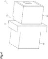
- the thickness of the measurement target S is not particularly limited, and the measurement target S may be thin, for example, as illustrated in FIG. 3 , or it may be thick as illustrated in FIG. 4 .
- the first housing 10 is a box member having a rectangular parallelepiped outer shape and having an internal space R1.
- the first housing 10 is a light projection block for projecting light L1 onto the measurement target S.
- the first housing 10 accommodates a light source 11 and a battery 13 in the internal space R1.
- the battery 13 supplies electric power to the light source 11 and to a spectrometer 21 and a communication control module 22 of the second housing to be described below.
- the light source 11 emits the light L1.
- Examples of the light source 11 include a light emitting diode or a mini lamp (incandescent light bulb).
- the light source 11 is provided so as to be changeable in the first housing 10.
- wavelength characteristics of the light L1 of the light source 11 are changeable in accordance with the measurement application. For example, when a light emitting diode in the ultraviolet range is used as the light source 11, it is possible to measure the fluorescence of the measurement target S. For example, when a white light emitting diode is used as the light source 11, it is possible to measure the chromaticity of the measurement target S. In addition, when a light emitting diode is used as the light source 11, it is possible to turn on and off the light source 11 in a short cycle with pulse lighting.
- One side surface 10b of the first housing 10 has a first opening 10a through which the light L1 emitted from the light source 11 passes.
- the first opening 10a having a circular cross section is provided on an optical axis of the light L1 from the light source 11 through an outer wall of the first housing 10.
- the first opening 10a is closed with a transparent member (such as an acrylic plate) that transmits the light L1. This makes it possible to prevent the measurement target S from directly coming in contact with the light source 11.
- a lens may be disposed in the first opening 10a so as to facilitate enhancement of the ability to collect the light L1.
- the first housing 10 has a light shielding property.
- the first housing 10 is formed of resin having high light shielding property so as not to obstruct wireless communication by a wireless communication unit 22a to be described below.
- the second housing 20 is box member having a rectangular parallelepiped outer shape and having an internal space R2.
- the second housing 20 is a light receiving block for receiving measurement light L2 from the measurement target S.
- the second housing 20 accommodates the spectrometer 21 and the communication control module 22 in the internal space R2.
- the spectrometer 21 receives the measurement light L2, and analyzes the measurement light L2 separately for individual wavelengths.
- Examples of the spectrometer 21 applicable include a micro-spectrometer or a micro-spectroscopic sensor.
- the communication control module 22 includes a central processing unit (CPU).
- the communication control module 22 includes: a wireless communication circuit configured to implement a wireless communication function with the outside; and a driver circuit configured to implement a control function of the light source 11.
- the communication control module 22 is electrically connected to the spectrometer 21, and to the light source 11 and the battery 13 provided in the first housing 10, via a cable C such as a flexible cable having flexibility or elasticity.
- a cable C such as a flexible cable having flexibility or elasticity.
- another side surface 10d adjacent to the one side surface 10b of the first housing 10 has a third opening 10c communicating with the internal space R1.
- the cable C can be pulled out from the inside of the first housing 10 to the outside via the third opening 10c.
- the communication control module 22 functionally includes a wireless communication unit (measurement result transmission unit, control signal reception unit) 22a, and a light source control unit 22b.
- the wireless communication unit 22a receives a control signal (also referred to as a control command) for controlling the light source 11 from the outside by wireless communication and also transmits a signal related to the measurement result of the spectrometer 21 to the outside by wireless communication.
- the light source control unit 22b performs control (ON/OFF control, etc.) of the light source 11 on the basis of the control signal received by the wireless communication unit 22a.
- One side surface 20b of the second housing 20 has a second opening 20a through which the measurement light L2 passes.
- the spectrometer 21 is disposed at a position in proximity to the second opening 20a in the internal space R2 in a state where an entrance slit of the spectrometer 21 faces the second opening 20a.
- the second opening 20a is closed with a transparent member (such as an acrylic plate) that transmits the measurement light L2. This makes it possible to prevent the measurement target S from directly coming in contact with the spectrometer 21.
- a lens may be disposed in the second opening 20a so as to facilitate enhancement of the ability to collect the measurement light L2.
- the second housing 20 has a light shielding property.
- the second housing 20 is formed of resin having high light shielding property so as not to obstruct wireless communication by a wireless communication unit 22a.
- the junction 30 joins the first housing 10 and the second housing 20 such that the relative positions of the first housing 10 and the second housing 20 are changeable. Specifically, the junction 30 slidably joins the second housing 20 to the first housing 10 in a direction to allow the first opening 10a and the second opening 20a to come close to or away from each other, in a state where the first opening 10a and the second opening 20a face each other. With this configuration, the junction 30 enables the light source 11 of the first housing 10 and the spectrometer 21 of the second housing 20 to be disposed at desired relative positions.
- the desired relative position in the present embodiment is a position where the optical axis of the light L1 to be emitted onto the measurement target S and the optical axis of the measurement light L2 output from the measurement target S are coaxial, being a position at which the first housing 10 and the second housing 20 are in contact with the measurement target S.
- the junction 30 is a sliding mechanism that slidably joins the second housing 20 to the first housing 10.
- the junction 30 includes an inserting part 30a and an insert receiving part 30b.
- the inserting part 30a is provided upright on one side surface 10b of the first housing 10. Specifically, the inserting part 30a is provided so as to protrude in a rectangular flat plate shape in a direction orthogonal to the one side surface 10b at an edge portion along one side of the one side surface 10b.
- the inserting part 30a has a rectangular cutout 30c formed to open to the distal end side and having a rectangular shape when viewed in a thickness direction of the inserting part 30a.
- the cutout 30c is provided in a central portion of the inserting part 30a in the direction along the one side of the one side surface 10b.
- the insert receiving part 30b is a recess (hole) formed along one side on an adjacent other side surface 20d on the one side surface 20b of the second housing 20.
- the insert receiving part 30b is formed in a rectangular cross section corresponding to the shape of the inserting part 30a, on the side wall portion 20c on the other side surface 20d side of the second housing 20.
- the insert receiving part 30b is provided on a bottom surface of a stepped portion 20e formed by cutting out an edge portion along the one side of the one side surface 20b.
- the insert receiving part 30b communicates with a cutout 30d formed in the side wall portion 20c.
- the cutout 30d opens on the bottom surface of the stepped portion 20e and is formed in a rectangular shape when it is viewed from the other side surface 20d.
- the cutout 30d is provided in a central portion of the other side surface 20d in the direction along the one side of the one side surface 20b.
- the cutout 30d is formed at a position corresponding to the position of the cutout 30c of the inserting part 30a in a state where the inserting part 30a is inserted in the insert receiving part 30b.
- the cable C can be pulled out from the inside of the second housing 20 to the outside via the cutouts 30c and 30d (refer to FIG. 6 ).
- the junction 30 is in a state where the inserting part 30a is slidably inserted into the insert receiving part 30b.
- the junction 30 joins the first housing 10 with the second housing 20 so as to bring the second housing 20 to a slidable state with respect to the first housing 10 (that is, so as to set the relative distance between the first housing 10 and the second housing 20 to be changeable) in a state where one side surfaces 10b and 20b (the first opening 10a and the second opening 20a) face each other.
- the junction 30 may include an inserting part on the second housing 20 and include an insert receiving part on the first housing 10 so as to bring the first housing 10 into a slidable state with respect to the second housing 20, as opposed to the above configuration.
- the wireless communication unit 22a can wirelessly communicate with a wireless gateway 71 connected to the network N.
- the wireless communication unit 22a receives a control signal for controlling the light source 11 from the network N via the wireless gateway 71 and also transmits a measurement result of the spectrometer 21 onto the network N via the wireless gateway 71.
- the data processing server 50 is connected to the network N.
- the data processing server 50 receives the measurement result of the spectrometer 21 from the network N.
- the data processing server 50 is a measurement result processing device that performs various data processing related to the received measurement result.
- the data processing server 50 performs at least one of data analysis, data calculation, and data accumulation on the basis of the received measurement result. For example, the data processing server 50 calculates and accumulates optical properties such as chromaticity and fluorescence properties of the measurement target S.
- the data processing server 50 transmits the processing result on the network N.
- the data processing server 50 constitutes a cloud server.
- the mobile information terminal 60 is a control terminal having an interface such as a touch panel.
- An example of the mobile information terminal 60 is a tablet terminal.
- the mobile information terminal 60 is not particularly limited, and may be a smartphone, a personal computer, or the like.
- the mobile information terminal 60 generates a control signal to control the light source 11 in accordance with operation (input to the interface) by an operator.
- the mobile information terminal 60 is capable of wireless communication with the wireless gateway 72 connected to the network N.
- the mobile information terminal 60 transmits the generated control signal onto the network via the wireless gateway 72.
- the mobile information terminal 60 receives various processing results of the data processing server 50 from the network N via the wireless gateway 72.
- the mobile information terminal 60 displays the received processing result on the interface. This allows the operator to confirm or refer to the processing result.
- the junction 30 is used to slide the second housing 20 with respect to the first housing 10 in a direction of allowing the first opening 10a and the second opening 20a to be separated from each other.
- the measurement target S is disposed between the one side surface 10b of the first housing 10 and the one side surface 20b of the second housing 20, and then, as illustrated in FIG. 3 , the second housing 20 is slid with respect to the first housing 10 in a direction to allow the first opening 10a and the second opening 20a to come closer to each other until the measurement target S abuts both the first housing 10 and the second housing 20 (or until a pressing force of a predetermined level or more is generated after the abutment).
- an operator operates the mobile information terminal 60 so as to transmit a control signal for driving the light source 11 from the mobile information terminal 60 to the network N.
- the wireless communication unit 22a receives the control signal from the network N, and then, the light source control unit 22b controls the light source 11 to emit the light L1 from the light source 11 on the basis of the control signal
- the emitted light L1 passes through the first opening 10a to be emitted on the measurement target S.
- the measurement light L2 as the transmitted light travels toward the second opening 20a and is then received and measured by the spectrometer 21.
- the measurement result of the spectrometer 21 is transmitted to the data processing server 50 via the network N by the wireless communication unit 22a.
- the data processing server 50 performs data processing of the received measurement result.
- the data processing server 50 transmits the data processing result to the mobile information terminal 60 via the network N.
- the processing result received on the mobile information terminal 60 is displayed on the interface.
- the spectroscopic measurement device 1 enables, with its junction 30, the first housing 10 and the second housing 20 to be positioned in a desired positional relationship, and consequently enables the light source 11 housed in the first housing 10 and the spectrometer 21 housed in the second housing 20 to be disposed at desired relative positions with a simple configuration.
- the first housing 10 and the second housing 20 have a light shielding property, and thus, can shield external light without a need to provide a separate configuration. Accordingly, it is possible to arrange the light source 11 and the spectrometer 21 at desired relative positions and downsize the apparatus.
- the junction 30 slidably joins the first housing 10 to the second housing 20 in a direction to allow the first opening 10a and the second opening 20a to come closer to or away from each other.
- the measurement target S can be firmly sandwiched and held by the first opening 10a and the second opening 20a regardless of the thickness of the measurement target S.
- the spectrometry system 100 includes the spectroscopic measurement device 1. Therefore, it is possible to obtain the above-described effects of being able to arrange the light source 11 and the spectrometer 21 at desired relative positions and to achieve downsizing of the apparatus. Furthermore, it is possible to have a configuration in which the spectroscopic measurement device 1 has no measurement result processing function, leading to downsizing of the spectroscopic measurement device 1.
- the spectrometry system 100 includes: a mobile information terminal 60 configured to generate a control signal for controlling the light source 11 in accordance with operation of an operator and transmit the control signal; a wireless communication unit 22a provided in the spectroscopic measurement device 1 and configured to receive the control signal from the mobile information terminal 60 via the network N; and a light source control unit 22b provided in the spectroscopic measurement device 1 and configured to control the light source 11 on the basis of the control signal received by the wireless communication unit 22a.
- a mobile information terminal 60 configured to generate a control signal for controlling the light source 11 in accordance with operation of an operator and transmit the control signal
- a wireless communication unit 22a provided in the spectroscopic measurement device 1 and configured to receive the control signal from the mobile information terminal 60 via the network N
- a light source control unit 22b provided in the spectroscopic measurement device 1 and configured to control the light source 11 on the basis of the control signal received by the wireless communication unit 22a.
- a spectroscopic measurement device 1B according to a second embodiment will be described with reference to FIG. 7 .
- points different from the first embodiment will be described, and duplicate description will be omitted.
- the spectroscopic measurement device 1B includes a junction 31 instead of the junction 30 (refer to FIG. 5 ).
- the spectroscopic measurement device 1B can perform reflected light measurement, that is, measurement including emission of the light L1 to the measurement target S and using reflected light reflected by the measurement target S as measurement light L2 corresponding to the light emission.
- the spectroscopic measurement device 1B can perform transmitted light measurement when the measurement target S is sufficiently thin.
- the junction 31 relatively rotatably joins the first housing 10 and the second housing 20 to each other so that the light source 11 of the first housing 10 and the spectrometer 21 of the second housing 20 are disposed at desired relative positions.
- the desired relative position is a position at which the optical axis of the light L1 emitted on the measurement target S and the optical axis of the measurement light L2 output from the measurement target S intersect at a predetermined angle.
- the desired relative position is a position at which the optical axis of the light L1 emitted on the measurement target S and the optical axis of the measurement light L2 output from the measurement target S are coaxial.
- the junction 31 can change the relative positions between the first housing 10 and the second housing 20 from the state where the first opening 10a and the second opening 20a face each other and where the optical axis of the light L1 and the optical axis of the measurement light L2 are coaxial to the state where the optical axis of the light L1 and the optical axis of the measurement light L2 intersect each other at a predetermined angle.
- the junction 31 is configured as a hinge that relatively rotatably joins the first housing 10 and the second housing 20.
- the junction 31 includes a first pipe portion 31a, a second pipe portion 31b, and a shaft portion 31c.
- the first pipe portion 31a has a substantially cylindrical shape.
- the first pipe portion 31a is provided at both end portions of an edge portion along one side of one side surface 10b of the first housing 10 in such a manner that its axis runs along the one side.
- the second pipe portion 31b has a substantially cylindrical shape.
- the second pipe portion 31b is provided at both end portions of an edge portion along one side of one side surface 20b of the second housing 20 in such a manner that its axis runs along the one side.
- the first pipe portion 31a and the second pipe portion 31b are disposed so that their axes are coaxial (axis A1).
- the first pipe portion 31a and the second pipe portion 31b are relatively rotatably joined to each other by the shaft portion 31c.
- the shaft portion 31c may be a shaft, a bolt, or the like.
- the junction 31 relatively rotatably joins the first housing 10 and the second housing 20 from the state where the one side surfaces 10b and 20b (the first opening 10a and the second opening 20a) are oriented in the same direction to the state where the one side surface 10b and 20b (the first opening 10a and the second opening 20a) faces each other.
- the first housing 10 and the second housing 20 are rotated relative to each other in a direction of allowing the first opening 10a and the second opening 20a to come closer to or away from each other by the junction 31.
- the spectroscopic measurement device 1B and the measurement target S are disposed so that the measurement target S is located at a point where the optical axis of the light L1 emitted on the measurement target S intersects the optical axis of the measurement light L2 output from the measurement target S.
- the light L1 is emitted from the light source 11.
- the emitted light L1 passes through the first opening 10a to be emitted on the measurement target S.
- the measurement light L2 as the reflected light travels toward the second opening 20a and is then received and measured by the spectrometer 21.
- the spectroscopic measurement device 1B can perform the transmitted light measurement solely for the measurement target S that is thin enough to set the optical axis of the light L1 to be emitted onto the measurement target S to be substantially coaxial with the optical axis of the measurement light L2 output from the measurement target S even when the measurement target S is disposed between the first housing 10 and the second housing 20.
- the first housing 10 and the second housing 20 are rotated relative to each other in a direction of allowing the first opening 10a and the second opening 20a to move away from each other by the junction 31.
- the measurement target S is disposed between the one side surface 10b of the first housing 10 and the one side surface 20b of the second housing 20, and then, the first housing 10 and the second housing 20 are relatively rotated in a direction to allow the first opening 10a and the second opening 20a to come close to each other until the measurement target S abuts both the first housing 10 and the second housing 20 (or until a pressing force of a predetermined level or more is generated after the abutment).
- the light L1 is emitted from the light source 11.
- the emitted light L1 passes through the first opening 10a to be emitted on the measurement target S.
- the measurement light L2 as the transmitted light travels toward the second opening 20a and is then received and measured by the spectrometer 21.
- the spectroscopic measurement device 1B has a configuration in which the junction 31 relatively rotatably joins the first housing 10 and the second housing 20, and thus, it is possible to relatively rotate the first housing 10 accommodating the light source 11 and second housing 20 accommodating the spectrometer 21 so as to arrange the light source 11 and the spectrometer 21 at desired relative angular positions.
- the junction 31 is capable of changing the relative positions to a position at which the first opening 10a and the second opening 20a face each other. Therefore, the transmitted light transmitted through the measurement target S can be received by the spectrometer 21 as the measurement light L2.
- the junction 31 can change the relative position to a position where the optical axis of the light L1 emitted on the measurement target S and the optical axis of the measurement light output from the measurement target S intersect with a predetermined angle. Therefore, the reflected light reflected by the measurement target S can be received by the spectrometer 21 as the measurement light L2.
- a spectroscopic measurement device 1C according to a third embodiment will be described with reference to FIG. 8 .
- points different from the first embodiment will be described, and duplicate description will be omitted.
- the spectroscopic measurement device 1C includes a junction 32 instead of the junction 30 (refer to FIG. 5 ).
- the spectroscopic measurement device 1C can perform reflected light measurement and transmitted light measurement.
- the junction 32 relatively rotatably joins the first housing 10 and the second housing 20 to each other so that the light source 11 of the first housing 10 and the spectrometer 21 of the second housing 20 are disposed at desired relative positions.
- the junction 32 slidably joins the second housing 20 with respect to the first housing 10 so that the light source 11 of the first housing 10 and the spectrometer 21 of the second housing 20 are disposed at desired relative positions.
- the desired relative position is a position at which the optical axis of the light L1 emitted on the measurement target S and the optical axis of the measurement light L2 output from the measurement target S intersect at a predetermined angle.
- the desired relative position is a position at which the optical axis of the light L1 emitted on the measurement target S and the optical axis of the measurement light L2 output from the measurement target S are coaxial.
- the junction 32 can change the relative positions between the first housing 10 and the second housing 20 from the state where the first opening 10a and the second opening 20a face each other and where the optical axis of the light L1 and the optical axis of the measurement light L2 are coaxial to the state where the optical axis of the light L1 and the optical axis of the measurement light L2 intersect each other at a predetermined angle.
- the junction 32 is configured as a hinge that relatively rotatably joins the first housing 10 and the second housing 20. Furthermore, the junction 32 is configured as a sliding mechanism that slidably joins the second housing 20 to the first housing 10.
- the junction 32 includes a first pipe portion 32a, a second pipe portion 32b, a shaft portion 32c, an inserting part 32d, and an insert receiving part 32e.
- the first pipe portion 32a has a substantially cylindrical shape.
- the first pipe portion 32a is provided at both end portions of an edge portion along one side of one side surface 10b of the first housing 10 so as to run along the one side.
- the second pipe portion 32b has a substantially cylindrical shape.
- the second pipe portion 32b is provided at both end portions of an edge portion along one side of one side surface 10b of the first housing 10 in such a manner that its axis runs along the one side, on the proximal end side of the inserting part 32d.
- the first pipe portion 32a and the second pipe portion 32b are disposed so that their axes are coaxial with each other (axis A2).
- the first pipe portion 32a and the second pipe portion 32b are relatively rotatably joined to each other by the shaft portion 32c.
- the shaft portion 32c may be a shaft, a bolt, or the like.
- the inserting part 32d is provided on an edge portion along one side of the one side surface 10b of the first housing 10 via the first pipe portion 32a and the second pipe portion 32b joined by the shaft portion 32c.
- the inserting part 32d is provided so as to protrude in a rectangular flat plate shape.
- the inserting part 32d has a rectangular cutout formed to open to the distal end side and having a rectangular shape when viewed in a thickness direction of the inserting part 32d.
- the cutout of the inserting part 32d is provided in a central portion of the inserting part 32d in the direction along the one side of the one side surface 10b.
- the insert receiving part 32e is a recess (hole) formed along one side on an adjacent other side surface 20d on the one side surface 20b of the second housing 20.
- the insert receiving part 32e is formed in a rectangular cross section corresponding to the shape of the inserting part 32d, on the side wall portion 20c on the other side surface 20d side of the second housing 20.
- the insert receiving part 32e is provided on a bottom surface of a stepped portion 20e formed by cutting out an edge portion along the one side of the one side surface 20b.
- the insert receiving part 32e communicates with a cutout formed in the side wall portion 20c.
- the cutout of the insert receiving part 32e opens on the bottom surface of the stepped portion 20e and is formed in a rectangular shape when it is viewed from the other side surface 20d.
- the cutout of the insert receiving part 32e is provided in the central portion of the other side surface 20d in the direction along the one side of the one side surface 20b.
- the cutout o the insert receiving part 32e is formed at a position corresponding to the position of the cutout of the inserting part 32d in a state where the inserting part 32d is inserted in the insert receiving part 32e.
- the cable C can be pulled out from the inside of the second housing 20 to the outside via the these cutouts.
- the junction 32 is in a state where the inserting part 32d is slidably inserted into the insert receiving part 32e.
- the junction 32 joins the first housing 10 with the second housing 20 so as to bring the second housing 20 to a slidable state with respect to the first housing 10 (that is, so as to set the relative distance between the first housing 10 and the second housing 20 to be changeable).
- the junction 32 may include an inserting part on the second housing 20 and include an insert receiving part on the first housing 10 so as to bring the first housing 10 into a slidable state with respect to the second housing 20, as opposed to the above configuration.
- junction 32 relatively rotatably joins the first housing 10 and the second housing 20 from the state where the one side surfaces 10b and 20b (the first opening 10a and the second opening 20a) are oriented in the same direction to the state where the one side surface 10b and 20b (the first opening 10a and the second opening 20a) faces each other.
- the junction 32 is used to slide the second housing 20 with respect to the first housing 10 so as to adjust the first housing 10 and the second housing 20 to be disposed with an appropriate interval.
- the first housing 10 and the second housing 20 are rotated relative to each other in a direction of allowing the first opening 10a and the second opening 20a to come closer to or away from each other by the junction 32.
- the spectroscopic measurement device 1C and the measurement target S are disposed so that the measurement target S is located at a point where the optical axis of the light L1 emitted on the measurement target S intersects the optical axis of the measurement light L2 output from the measurement target S.
- the light L1 is emitted from the light source 11.
- the emitted light L1 passes through the first opening 10a to be emitted on the measurement target S.
- the measurement light L2 as the reflected light travels toward the second opening 20a and is then received and measured by the spectrometer 21.
- the junction 32 is used to relatively rotate the first housing 10 and the second housing 20 in a direction of allowing the first opening 10a and the second opening 20a to come closer to or away from each other so as to set the optical axis of the light L1 emitted onto the measurement target S and the optical axis of the measurement light L2 output from the measurement target S to be coaxial.
- the measurement target S is disposed between the one side surface 10b of the first housing 10 and the one side surface 20b of the second housing 20, and then, the first housing 10 and the second housing 20 are relatively rotated in a direction to allow the first opening 10a and the second opening 20a to come close to each other until the measurement target S abuts both the first housing 10 and the second housing 20 (or until a pressing force of a predetermined level or more is generated after the abutment).
- the light L1 is emitted from the light source 11.
- the emitted light L1 passes through the first opening 10a to be emitted on the measurement target S.
- the measurement light L2 as the transmitted light travels toward the second opening 20a and is then received and measured by the spectrometer 21.
- the spectroscopic measurement device 1C has a configuration in which the junction 32 relatively rotatably joins the first housing 10 and the second housing 20, and thus, it is possible to relatively rotates the first housing 10 accommodating the light source 11 and second housing 20 accommodating the spectrometer 21 so as to arrange the light source 11 and the spectrometer 21 at desired relative angular positions.
- the junction 32 slidably joins the first housing 10 to the second housing 20 in a direction to allow the first opening 10a and the second opening 20a to come closer to or away from each other.
- the measurement target S can be firmly sandwiched and held by the first opening 10a and the second opening 20a regardless of the thickness of the measurement target S.
- the junction 32 is capable of changing the relative positions to a position at which the first opening 10a and the second opening 20a face each other. Therefore, the transmitted light transmitted through the measurement target S can be received by the spectrometer 21 as the measurement light L2.
- the junction 32 can change the relative position to a position where the optical axis of the light L1 emitted on the measurement target S and the optical axis of the measurement light output from the measurement target S intersect with a predetermined angle. Therefore, the reflected light reflected by the measurement target S can be received by the spectrometer 21 as the measurement light L2.
- the spectroscopic measurement device 1B may further include an attachment 40.
- the attachment 40 makes it easy to hold the light source 11 of the first housing 10 and the spectrometer 21 of the second housing 20 in a state of being disposed in desired relative positions for performing reflected light measurement.
- the desired relative position is a position at which the optical axis of the light L1 emitted on the measurement target S and the optical axis of the measurement light L2 output from the measurement target S intersect at a predetermined angle (here, 45 degrees).
- a predetermined angle here, 45 degrees
- the attachment 40 detachably holds the first housing 10 and the second housing 20 so that the light source 11 of the first housing 10 and the spectrometer 21 of the second housing 20 are disposed at desired relative positions.
- the attachment 40 includes a main body 40a, a first holding part 40c, and a second holding part 40d.
- the main body 40a is a block member including a planar lower surface 40b.
- the main body 40a has a configuration in which the main body 40a is mounted on the measurement target S, and this configuration allows the lower surface 40b in contact with the measurement target S to function as a position regulator 40g that regulates the position of the measurement target S.
- the main body 40a includes: a first columnar member 40e having a quadrangular prism-like outer shape having an axial direction inclined with respect to the lower surface 40b; a second columnar member 40f having a quadrangular columnar shape having an axial direction orthogonal to the lower surface 40b.
- the first holding part 40c is provided on the upper surface of the first columnar member 40e, while the second holding part 40d is provided on the upper surface of the second columnar member 40f.
- the first holding part 40c detachably holds the first housing 10 with respect to the main body 40a.
- the first holding part 40c includes a wall portion upright on the upper surface of the first columnar member 40e.
- the wall portion constituting the first holding part 40c is formed so as to be engaged with the first housing 10 on three sides except for the second holding part 40d side.
- the attachment 40 uses the first holding part 40c to hold the first housing 10 in a state where the first opening 10a faces the main body 40a side (upper surface side of the first columnar member 40e).
- the first housing 10 may be detachably secured to the main body 40a or the first holding part 40c by a screw or the like.
- the second holding part 40d detachably holds the second housing 20 with respect to the main body 40a.
- the second holding part 40d includes a wall portion upright on the upper surface of the second columnar member 40f.
- the wall portion constituting the second holding part 40d is formed so as to be engaged with the second housing 20 on three sides except for the side of the first holding part 40c.
- the attachment 40 uses the second holding part 40d to hold the second housing 20 in a state where the second opening 20a faces the main body 40a side (upper surface side of the second columnar member 40f).
- the second housing 20 may be detachably secured to the main body 40a or the second holding part 40d by a screw or the like.
- the distance between the first holding part 40c and the second holding part 40d is set to a distance that enables simultaneously holding the first housing 10 and the second housing 20 of the spectroscopic measurement device 1B (that is, the first housing 10 and the second housing 20 joined by the junction 31).
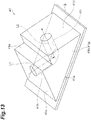
- the main body 40a internally includes: a first optical path 40h being an optical path of the light L1 emitted onto the measurement target S and continuous with the first opening 10a; and a second optical path 40i being an optical path of the measurement light L2 output from the measurement target S and continuous with the second opening 20a.
- first optical path 40h opens to the upper surface of the first columnar member 40e.
- the other end of the first optical path 40h opens to the lower surface 40b of the main body 40a.
- One end of the second optical path 40i opens to the upper surface of the second columnar member 40f.
- the other end of the second optical path 40i opens to the same region as the other end of the first optical path 40h, out of the lower surface 40b of the main body 40a. That is, the other end of the first optical path 40h and the other end of the second optical path 40i share an opening portion on the lower surface 40b of the main body 40a.
- the angle between the first optical path 40h and the second optical path 40i is set to a predetermined angle in accordance with the measurement application.
- the angle between the first optical path 40h and the second optical path 40i is set to 45 degrees as an example, but it is not limited thereto, and may be set to 90 degrees, for example.
- the attachment 40 has a light shielding property.
- the attachment 40 is formed of resin having high light shielding property so as not to obstruct wireless communication by a wireless communication unit 22a.
- the attachment 40 is mounted on the measurement target S.
- the first housing 10 is mounted on the first holding part 40c so that the first opening 10a faces the upper surface of the first columnar member 40e.
- the second housing 20 is mounted on the second holding part 40d so that the second opening 20a faces the upper surface of the second columnar member 40f.
- the optical axis of the light L1 emitted on the measurement target S and the optical axis of the measurement light L2 output from the measurement target S are set to intersect each other at a predetermined angle (here, 45 degrees) at a point corresponding to the other end of the first optical path 40h opened in the lower surface 40b of the main body 40a (that is, the other end of the second optical path 40i).
- the light L1 is emitted from the light source 11.
- the emitted light L1 passes through the first opening 10a and the first optical path 40h to be emitted on the measurement target S.
- the measurement light L2 as the reflected light passes the second optical path 40i and travels toward the second opening 20a, so as to be received and measured by the spectrometer 21.
- the spectroscopic measurement device 1B further includes the attachment 40 configured to detachably hold the first housing 10 and the second housing 20 joined by the junction 31, making it possible to use the attachment 40 to hold the first housing 10 and the second housing 20 positioned in a desired positional relationship by the junction 31.
- the attachment 40 has a light shielding property, and the attachment 40 internally includes the first optical path 40h and the second optical path 40i.
- the configuration in this case, would suppress invasion of external light into the first optical path 40h and the second optical path 40i provided inside the attachment 40.
- the attachment 40 has a lower surface 40b that functions as the position regulator 40g that regulates the position of the measurement target S. Therefore, it is possible to use the position regulator 40g to hold the measurement target S.
- the spectroscopic measurement device 1B according to the second embodiment may further include the attachment 40.
- the spectroscopic measurement device 1C according to the third embodiment may further include the attachment 40.
- the spectroscopic measurement device 1B of the second embodiment may further include an attachment 41.
- the attachment 41 makes it easy to hold the light source 11 of the first housing 10 and the spectrometer 21 of the second housing 20 in a state of being disposed in desired relative positions for performing reflected light measurement.
- the desired relative position is a position at which the optical axis of the light L1 emitted on the measurement target S and the optical axis of the measurement light L2 output from the measurement target S intersect at a predetermined angle (here, 90 degrees).
- a predetermined angle here, 90 degrees
- the attachment 41 detachably holds the first housing 10 and the second housing 20 so that the light source 11 of the first housing 10 and the spectrometer 21 of the second housing 20 are disposed at desired relative positions.
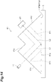
- the attachment 41 includes a main body 41a, an slope 41c, and an slope 41d.
- the main body 41a is a block member including a planar lower surface 41b.
- the main body 41a has a configuration in which the main body 41a is mounted on the measurement target S, and this configuration allows the lower surface 41b in contact with the measurement target S to function as a position regulator 41g that regulates the position of the measurement target S.
- the main body 41a has a substantially triangular prism shape.
- the main body 41a has an isosceles triangular prism shape having side surfaces, namely, the lower surface 41b and a pair of slopes 41c and 41d each of which being inclined by 45 degrees with respect to the lower surface 41b and intersecting with each other.
- the main body 41a has, in its upper portion, a cutout 41e extending in axial directions.
- the cutout 41a is a space including a plane orthogonal to the slope 41c and a plane perpendicular to the slope 41d.
- the cutout 41e is formed at a position corresponding to a right angle corner of the isosceles triangular prism shape.
- the slope 41c functions as a first holding part to detachably hold the first housing 10 with respect to the main body 41a.
- the attachment 41 holds the first housing 10 in a state where the slope 41c allows the first opening 10a to face the main body 41a side (the slope 41c side).
- the slope 41d functions as a second holding part to detachably hold the second housing 20 with respect to the main body 41a.
- the attachment 41 holds the second housing 20 in a state where the slope 41d allows the second opening 20a to face the main body 41a side (the slope 41d side).
- an extending direction of the cutout 41e of the main body 41a is defined as the axis A1 (refer to FIG. 7 ) of the junction 31, and the junction 31 is disposed in the cutout 41e in this state.
- the first housing 10 is mounted on the slope 41c
- the second housing 20 is mounted on the slope 41d.
- the first housing 10 is supported by the slope 41c while the second housing 20 is supported by the slope 41d.
- the junction 31 is pulled in individual directions by a component along the slope 41c of the gravity acting on the first housing 10 and a component along the slope 41d of the gravity acting on the second housing 20.
- forces acting on the first housing 10 and the second housing 20 joined by the junction 31 are balanced, so as to be able to stably and detachably hold the two housings on the attachment 41.
- first housing 10 and the second housing 20 may be detachably secured to the main body 41a by a screw or the like.
- the main body 41a internally includes: a first optical path 41h being an optical path of the light L1 emitted onto the measurement target S and continuous with the first opening 10a; and a second optical path 41i being an optical path of the measurement light L2 output from the measurement target S and continuous with the second opening 20a.
- the angle between the first optical path 41h and the second optical path 41i is set to a predetermined angle in accordance with the measurement application.
- the angle between the first optical path 41h and the second optical path 41i is set to 90 degrees as an example, but it is not limited thereto, and may be set to 45 degrees, for example.
- the attachment 41 has a light shielding property.
- the attachment 41 here is formed of a resin having high light shielding property so as not to hamper wireless communication by the wireless communication unit 22a.
- the attachment 41 is mounted on the measurement target S.
- the first housing 10 and the second housing 20 joined by the junction 31 are arranged such that the junction 31 is mounted at the cutout 41e portion of the main body 41a, the first housing 10 is mounted on the slope 41c, and the second housing 20 is mounted on the slope 41d.
- the first opening 10a is set to face the main body 41a side and the second opening 20a is set to face the main body 41a side.
- the optical axis of the light L1 emitted on the measurement target S and the optical axis of the measurement light L2 output from the measurement target S are set to intersect each other at a predetermined angle (here, 90 degrees) at a point corresponding to the other end of the first optical path 41h opened in the lower surface 41b of the main body 41a (that is, the other end of the second optical path 41i).
- the light L1 is emitted from the light source 11.
- the emitted light L1 passes through the first opening 10a and the first optical path 41h to be emitted on the measurement target S.
- the measurement light L2 as the reflected light passes the second optical path 41i and travels toward the second opening 20a, so as to be received and measured by the spectrometer 21.
- the spectroscopic measurement device 1B further includes the attachment 41 to detachably hold the first housing 10 and the second housing 20 joined by the junction 31, making it possible to use the attachment 41 to hold the first housing 10 and the second housing 20 positioned in a desired positional relationship by the junction 31.
- the attachment 41 has a light shielding property, and the attachment 41 internally includes the first optical path 41h and the second optical path 41i.
- the configuration in this case, would suppress invasion of external light into the first optical path 41h and the second optical path 41i provided inside the attachment 41.
- the attachment 41 has a lower surface 41b that functions as the position regulator 41g that regulates the position of the measurement target S. Therefore, it is possible to use the position regulator 41g to hold the measurement target S.
- the spectroscopic measurement device 1B according to the second embodiment may further include the attachment 41.
- the spectroscopic measurement device 1C according to the third embodiment may further include the attachment 41.
- the spectroscopic measurement device 1B of the second embodiment may further include an attachment 42.
- the attachment 42 makes it easy to hold the light source 11 of the first housing 10 and the spectrometer 21 of the second housing 20 in a state of being disposed in desired relative positions for performing fluorescence measurement.
- the desired relative position is a position at which the optical axis of the light L1 emitted onto a cuvette S1 containing the measurement target S and the optical axis of the measurement light L2 output from the measurement target S intersect at a predetermined angle (here, 90 degrees).
- the cuvette S1 herein is a container formed of a transparent member (glass, resin, quartz, or the like) that transmits the light L1 and the measurement light L2, and accommodates the measurement target S.
- a transparent member glass, resin, quartz, or the like
- the upper side (cap side) of the cuvette S1 will be referred to as “upper side” and the opposite side will be described as “lower side” for the sake of convenience.
- the attachment 42 detachably holds the first housing 10 and the second housing 20 so that the light source 11 of the first housing 10 and the spectrometer 21 of the second housing 20 are disposed at desired relative positions.
- the attachment 42 includes a main body 42a, a first holding part 42b, and a second holding part 42c.
- the main body 42a is a block member having a substantially parallelepiped shape.
- the upper surface of the main body 42a has a recess 42d formed to have a rectangular cross section.
- the cuvette S1 having a predetermined external dimension is fitted into the recess 42d. In other words, the cuvette S1 can be inserted into the recess 42d without a gap.
- the first holding part 42b detachably holds the first housing 10 with respect to the main body 42a.
- the first holding part 42b includes a wall portion upright on a portion (L-shaped edge portion) of the edge portion on one side surface 42e of the main body 42a.
- the first housing 10 is positioned on the one side surface 42e by the first holding part 42b and is detachably secured to the main body 42a or the first holding part 42b by a screw or the like. Note that the first holding part 42b may hold the first housing 10 by engaging with the first housing 10.
- the second holding part 42c detachably holds the second housing 20 with respect to the main body 42a.
- the second holding part 42c includes a wall portion upright on a part of the edge portion (L-shaped edge portion) on another side surface 42f adjacent to the one side surface 42e of the main body 42a.
- the second housing 20 is positioned on the other side surface 42f by the second holding part 42c and is detachably secured to the main body 42a or the second holding part 42c by a screw or the like. Note that the second holding part 42c may hold the second housing 20 by engaging with the second housing 20.
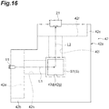
- the main body 42a internally includes: a first optical path 42h being an optical path of the light L1 emitted onto the cuvette S1 and continuous with the first opening 10a; and a second optical path 42i being an optical path of the measurement light L2 output from the measurement target S and continuous with the second opening 20a.
- One end of the first optical path 42h opens to the one side surface 42e of the main body 42a.
- the other end of the first optical path 42h opens to the inner wall surface of the recess 42d of the main body 42a.
- One end of the second optical path 42i opens to the other side surface 42f of the main body 42a.
- the other end of the second optical path 42i opens to the other surface adjacent to the inner wall surface of the recess 42d of the main body 42a.
- the angle between the first optical path 42h and the second optical path 42i is set to a predetermined angle in accordance with the measurement application.
- the angle between the first optical path 42h and the second optical path 42i is set to 90 degrees as an example, but it is not limited thereto, and may be set to 45 degrees, for example.
- the attachment 42 has a light shielding property.
- the attachment 42 here is formed of a resin having high light shielding property so as not to hamper wireless communication by the wireless communication unit 22a.
- the first housing 10 is held by the first holding part 42b so that the first opening 10a faces the side surface 42e side (the first holding part 42b side) of the main body 42a.
- the second housing 20 is held by the second holding part 42c so that the second opening 20a faces the other side surface 42f side (the second holding part 42c side) of the main body 42a.
- the cuvette S1 is fitted into the recess 42d.
- the optical axis of the light L1 emitted on the measurement target S contained in the cuvette S1 and the optical axis of the measurement light L2 (fluorescence) output from the measurement target S intersect with each other at a predetermined angle (here, 90 degrees) at a center of the recess 42d of the main body 42a in plan view.
- the light L1 is emitted from the light source 11.
- the emitted light L1 passes through the first opening 10a and the first optical path 42h to be emitted on the measurement target S.
- the measurement light L2 as the fluorescence passes the second optical path 42i and travels toward the second opening 20a, so as to be received and measured by the spectrometer 21.
- the spectroscopic measurement device 1B further includes the attachment 42 to detachably hold the first housing 10 and the second housing 20 joined by the junction 31, making it possible to use the attachment 42 to hold the first housing 10 and the second housing 20 positioned in a desired positional relationship by the junction 31.
- the spectroscopic measurement device 1B can allow the recess 42d of the attachment 42 to function as a position regulator 42g for regulating the position of the inserted cuvette S1, enabling the cuvette S1 to be reliably held in the recess 42d.
- the attachment 42 has a light shielding property, and the attachment 42 internally includes the first optical path 42h and the second optical path 42i.
- the configuration in this case, makes it possible to suppress invasion of external light into the first optical path 42h and the second optical path 42i provided inside the attachment 42.
- the spectroscopic measurement device 1C may further include an attachment 43.
- the attachment 43 makes it easy to hold the light source 11 of the first housing 10 and the spectrometer 21 of the second housing 20 in a state of being disposed in desired relative positions for performing transmitted light measurement.
- the desired relative position is a position at which the optical axis of the light L1 emitted on the cuvette S1 containing the measurement target S and the optical axis of the measurement light L2 output from the measurement target S are coaxial.
- the attachment 43 detachably holds the first housing 10, the cuvette S1, and the second housing 20 sequentially in this order.
- the attachment 43 includes a main body 43a, wall portions 43b and 43e, and column portions 43c and 43d.
- the main body 43a has a rectangular plate shape.
- the wall portions 43b and 43e and the column portions 43c and 43d are provided upright on the main body 43a.
- the wall portions 43b and 43e and the column portions 43c and 43d hold the first housing 10, the cuvette S1 containing the measurement target S, and the second housing 20.
- the wall portion 43b is formed in an L shape along an edge portion on one side in the longitudinal direction of the main body 43a in plan view. Specifically, the wall portion 43b includes a portion along one end edge of the main body 43a and a portion along one side edge continuous to the one end edge.
- the wall portion 43e is formed in an L shape along the other edge portion on the opposite side to the one side in the longitudinal direction of the main body 43a in plan view. Specifically, the wall portion 43e has a portion along the other end edge opposite to the one end edge of the main body 43a, and a portion along one side edge continuing from the other end edge.
- the column portion 43c is formed between the wall portions 43b and 43e in the longitudinal direction of the main body 43a so as to be continuous with the wall portions 43b and 43e.
- the column portion 43c is formed thicker in the short-side direction of the main body 43a than the wall portions 43b and 43e.
- the column portion 43d is provided upright at a predetermined interval in the short-side direction of the main body 43a with respect to the column portion 43c. This predetermined interval corresponds to the external dimension of the cuvette S1 (length of the cuvette S1 in the short-side direction of the main body 43a in a state where the cuvette S1 is held by the attachment 43).
- the column portion 43d is formed such that the width of the main body 43a in the longitudinal direction is substantially the same as the width of the column portion 43c. This width corresponds to the external dimension of the cuvette S1 (length of the cuvette S1 in the longitudinal direction of the main body 43a in a state where the cuvette S1 is held by the attachment 43).
- the wall portion 43b and the column portions 43c and 43d define a space to contain the first housing 10 so as to be engaged with the first housing 10.
- the wall portion 43e and the column portions 43c and 43d define a space to contain the second housing 20 so as to be engaged with the second housing 20.
- the first housing 10 and the second housing 20 may be detachably secured to at least one of the main body 43a, the wall portions 43b and 43e, and the column portions 43c and 43d by a screw or the like.
- the attachment 43 holds the first housing 10 such that the first opening 10a faces the cuvette S1 side by the wall portion 43b and the column portions 43c and 43d. Furthermore, the attachment 43 holds the second housing 20 such that the second opening 20a faces the cuvette S1 side by the wall portion 43e and the column portions 43c and 43d. That is, the attachment 43 holds the first housing 10 and the second housing 20 so that the first opening 10a and the second opening 20a face each other. In other words, the attachment 43 holds the first housing 10 and the second housing 20 such that the optical axis of the light L1 emitted on the cuvette S1 and the optical axis of the measurement light L2 output from the cuvette S1 are coaxial. Furthermore, the attachment 43 holds the cuvette S 1 by the column portions 43c and 43d.
- the column portion 43c may include, at its tip, a pressing part for pressing at least one of the first housing 10 and the second housing 20 toward the main body 43a side.
- the column portion 43c may have an elongated pressing part extending from the tip of the column portion 43c to both ends in the longitudinal direction of the main body 43a at a position having a height substantially the same as the height of the upper surface of the first housing 10 (the second housing 20) in illustration.
- the column portion 43c may have a substantially T shape including the pressing part formed at the distal end side as viewed in the short-side direction of the main body 43a.
- the attachment 43 can firmly hold the first housing and the second housing.
- the first housing 10 and the second housing 20 are rotated relative to each other by the junction 32 such that the first opening 10a and the second opening 20a face each other, and together with this, the second housing 20 is slid with respect to the first housing 10 so that the length between the first opening and the second opening becomes equal to the width of the column portions 43c and 43d in the longitudinal direction of the main body 43a.
- the first housing 10 is disposed between the wall portion 43b and the column portions 43c and 43d
- the second housing 20 is disposed between the wall portion 43e and the column portions 43c and 43d.
- the cuvette S1 is disposed between the column portions 43c and 43d.
- the light L1 is emitted from the light source 11.
- the emitted light L1 passes through the first opening 10a and is directed to the cuvette S1.
- the measurement light L2 as the transmitted light travels toward the second opening 20a, and then is received and measured by the spectrometer 21.
- the spectroscopic measurement device 1C further includes the attachment 43 to detachably hold the first housing 10 and the second housing 20 joined by the junction 32, making it possible to use the attachment 43 to hold the first housing 10 and the second housing 20 positioned in a desired positional relationship by the junction 32.
- the spectroscopic measurement device 1C can allow the column portions 43c and 43d of the attachment 43 to function as the position regulator 43f for regulating the position of the cuvette S1, enabling the cuvette S1 to be reliably held by the position regulator 43f.
- the spectroscopic measurement device 1 and the mobile information terminal 60 may be configured to be capable of directly communicating without going through a network.
- the measurement result of the spectrometer 21 of the spectroscopic measurement device 1 may be directly transmitted wirelessly from the wireless communication unit 22a to the mobile information terminal 60, and then, the measurement result may be processed by the mobile information terminal 60, and the processing result may be displayed on the interface of the mobile information terminal 60.
- a control signal to control the light source 11 may be directly transmitted from the mobile information terminal 60 to the wireless communication unit 22a by radio.
- the mobile information terminal 60 functions as a control terminal and a measurement result processing device.
- one side surface 10b on which the first opening 10a is formed out of the outer surfaces of the first housing 10 may include a rubber layer.
- one side surface 20b on which the second opening 20a is formed out of the outer surfaces of the second housing 20 may include a rubber layer. This can enhance the light shielding property.
- the first housing 10 and the second housing 20 can be abutted against the measurement target S via the rubber layer, the first housing 10 and the second housing 20 can be firmly pressed against the measurement target S, making it possible to strongly hold the measurement target S.
- the transmitted light measurement or the reflected light measurement can be replaced by the fluorescence measurement of measuring the fluorescence generated in the measurement target S as the measurement light L2.
- fluorescence measurement may be performed in place of transmitted light measurement in a case where the relative positions of the light source 11 and the spectrometer 21 are such that the optical axis of the light L1 and the optical axis of the measurement light L2 are coaxial.
- Fluorescence measurement may be performed in place of reflected light measurement in a case where the relative positions of the light source 11 and the spectrometer 21 are such that the optical axis of the light L1 and the optical axis of the measurement light L2 intersect at a predetermined angle.
- the spectroscopic measurement device or the spectrometry system according to the above embodiment may include a plurality of types of attachments (for example, all or a part of the attachments 40 to 43).
- one of the plurality of types of attachments is selected in accordance with the desired relative positions of the light source 11 and the spectrometer 21 as a desired arrangement in the spectrometry.
- Spectrometry is performed by using the selected attachment.
- one aspect of the present invention can also be regarded as a spectrometric method of performing spectrometry using the spectroscopic measurement device or the spectrometry system according to the above embodiment.
- the technology makes it possible to provide a spectroscopic measurement device capable of disposing the light source and the spectrometer at desired relative positions and downsizing the device, and a spectrometry system including the spectroscopic measurement device.
Landscapes
- Physics & Mathematics (AREA)
- Spectroscopy & Molecular Physics (AREA)
- General Physics & Mathematics (AREA)
- Immunology (AREA)
- Health & Medical Sciences (AREA)
- Life Sciences & Earth Sciences (AREA)
- Chemical & Material Sciences (AREA)
- Analytical Chemistry (AREA)
- Biochemistry (AREA)
- General Health & Medical Sciences (AREA)
- Pathology (AREA)
- Mathematical Physics (AREA)
- Theoretical Computer Science (AREA)
- Engineering & Computer Science (AREA)
- Investigating Or Analysing Materials By Optical Means (AREA)
- Spectrometry And Color Measurement (AREA)
Abstract
Description
- One aspect of the present invention relates to a spectroscopic measurement device and a spectrometry system.
- An apparatus described in
Patent Literature 1 is known as an example of a conventional spectroscopic measurement device. The apparatus described inPatent Literature 1 uses a light source lamp (light source) to emit light onto a specimen (measurement target) mounted on a specimen table, and detects the light (measurement light) output from the specimen corresponding to the light emission by using an integrating sphere and a photodetector (spectrometer), so as to measure optical properties of the specimen. - Patent Literature 1: Japanese Patent No.
3446120 - Meanwhile, relative positions at which the light source and the spectrometer should be disposed are different between the case of measuring transmitted light, that is, light transmitted through the measurement target, and the case of measuring reflected light, that is, light reflected by the measurement target. Accordingly, the spectroscopic measurement device described above includes: a motor-rotatable first rotating member constituting an optical path of the light emitted onto the measurement target; and a motor-rotatable second rotating member constituting an optical path of the measurement light output from the measurement target, in order to arrange the light source and the spectrometer at desired relative positions. This, however, would complicate the configuration and enlarge the apparatus. In an attempt, in particular, to shield external light that is likely to greatly influence the measurement of the optical properties of the measurement target, for example, it would be necessary to dispose the whole device in a housing having a light shielding property, and this would further enlarge the device.
- In view of the above, one aspect of the present invention is to provide a spectroscopic measurement device capable of disposing a light source and a spectrometer at desired relative positions and downsizing the device, and provide a spectrometry system including the spectroscopic measurement device.
- A spectroscopic measurement device according to one aspect of the present invention is a spectroscopic measurement device configured to emit light onto a measurement target to measure measurement light output from the measurement target corresponding to the light emission, the device including: a first housing having a light shielding property and configured to house a light source that emits light and having a first opening through which the light emitted from the light source passes; a second housing having a light shielding property and having a second opening through which the measurement light passes and configured to house a spectrometer that receives the measurement light that has passed through the second opening; and a junction configured to join the first housing and the second housing such that relative positions of the first housing and the second housing can be changed.
- The spectroscopic measurement device enables, with its junction, the first housing and the second housing to be positioned in a desired positional relationship, and consequently enables the light source housed in the first housing and the spectrometer housed in the second housing to be disposed at desired relative positions with a simple configuration. Additionally, the first housing and the second housing have a light shielding property, and thus, can shield external light without a need to provide a separate configuration. Accordingly, it is possible to arrange the light source and the spectrometer at desired relative positions and downsize the apparatus.
- In the spectroscopic measurement device, the junction may relatively rotatably join the first housing and the second housing. In this case, by relatively rotating, by the junction, the first housing that houses the light source and the second housing that houses the spectrometer, it is possible to arrange the light source and the spectrometer at desired relative angular positions.
- In the spectroscopic measurement device according to one aspect of the present invention, the junction may slidably join one of the first housing and the second housing to the other in a direction to allow the first opening and the second opening to come closer to or away from each other. In this case, the measurement target can be firmly sandwiched and held by the first opening and the second opening regardless of the thickness of the measurement target.
- In the spectroscopic measurement device according to one aspect of the present invention, the junction may be capable of changing the relative positions to a position at which the first opening and the second opening face each other. In this case, the transmitted light, that is, light transmitted through the measurement target, can be received by the spectrometer as measurement light.
- In the spectroscopic measurement device according to one aspect of the present invention, the junction may be configured to be able to change the relative position to a position at which an optical axis of the light to be emitted onto the measurement target and an optical axis of the measurement light output from the measurement target intersect at a predetermined angle. In this case, reflected light reflected by the measurement target can be received by the spectrometer as measurement light.
- The spectroscopic measurement device according to one aspect of the present invention may further include an attachment to detachably hold the first housing and the second housing joined by the junction. In this case, the first housing and the second housing positioned in a desired positional relationship by the junction can be held by the attachment.
- In the spectroscopic measurement device according to one aspect of the present invention, the attachment may have a light shielding property, and may internally include: a first optical path being an optical path of the light emitted onto the measurement target and is continuous with the first opening; and a second optical path being an optical path of the measurement light output from the measurement target and is continuous with the second opening. The configuration, in this case, would suppress invasion of external light into the first optical path and the second optical path provided inside the attachment.
- In the spectroscopic measurement device according to one aspect of the present invention, the attachment may have a position regulator to regulate a position of the measurement target or a position of a container accommodating the measurement target. In this case, it is possible to hold the measurement target or the container accommodating the measurement target by the position regulator.
- A spectrometry system according to one aspect of the present invention includes: the above-described spectroscopic measurement device; a measurement result transmission unit provided in the spectroscopic measurement device and configured to transmit a measurement result of the spectrometer; and a measurement result processing device configured to receive the measurement result of the spectrometer from the measurement result transmission unit directly or through a network and perform processing of the measurement result.
- Since this spectrometry system includes the above-described spectroscopic measurement device, it is possible to obtain the above effect of enabling the light source and the spectrometer to be disposed at desired relative positions and enabling downsizing of the device. Furthermore, it is possible to have a configuration in which the spectroscopic measurement device has no measurement result processing function, leading to downsizing of the spectroscopic measurement device.
- The spectrometry system according to one aspect of the present invention further includes: a control terminal configured to generate a control signal for controlling the light source in accordance with operation of an operator and transmit the control signal; a control signal reception unit provided in the spectroscopic measurement device and configured to receive the control signal from the control terminal directly or through a network; and a light source control unit provided in the spectroscopic measurement device and configured to control the light source on the basis of the control signal received by the control signal reception unit. With this configuration, it is possible to remotely operate the light source.
- According to one aspect of the present invention, it is possible to provide a spectroscopic measurement device capable of disposing the light source and the spectrometer at desired relative positions and downsizing the device, and a spectrometry system including the spectroscopic measurement device.
-
-
FIG. 1 is a configuration diagram illustrating a spectrometry system according to a first embodiment. -
FIG. 2 is a perspective view illustrating a spectroscopic measurement device ofFIG. 1 . -
FIG. 3 is a perspective view illustrating a state of measuring the measurement light in the spectroscopic measurement device ofFIG. 2 . -
FIG. 4 is a perspective view illustrating a state where measurement light is measured by the spectroscopic measurement device ofFIG. 2 . -
FIG. 5 is a perspective view illustrating a state where the spectroscopic measurement device ofFIG. 2 is disassembled. -
FIG. 6 is a diagram schematically illustrating a cross section taken along line VI-VI ofFIG. 3 . -
FIG. 7 is a perspective view illustrating a spectroscopic measurement device according to a second embodiment. -
FIG. 8 is a perspective view illustrating a spectroscopic measurement device according to a third embodiment. -
FIG. 9 is a configuration diagram illustrating a spectroscopic measurement device according to a modification. -
FIG. 10 is a perspective view illustrating a first optical path and a second optical path provided in an attachment of the spectroscopic measurement device ofFIG. 9 . -
FIG. 11 is a view schematically illustrating a cross section taken along line XI-XI ofFIG. 9 . -
FIG. 12 is a configuration diagram illustrating a spectroscopic measurement device according to a modification. -
FIG. 13 is a perspective view illustrating a first optical path and a second optical path provided in an attachment of the spectroscopic measurement device ofFIG. 12 . -
FIG. 14 is a diagram schematically illustrating a cross section taken along line XIV-XIV ofFIG. 12 . -
FIG. 15 is a configuration diagram illustrating a spectroscopic measurement device according to a modification. -
FIG. 16 is a diagram schematically illustrating a cross section taken along line XVI-XVI ofFIG. 15 . -
FIG. 17 is a configuration diagram illustrating a spectroscopic measurement device according to a modification. -
FIG. 18 is a configuration diagram illustrating a spectroscopic measurement device according to a modification. - Hereinafter, one embodiment of the present invention will be described in detail with reference to the accompanying drawings. In the following, the same or equivalent elements are denoted by the same reference numerals, and duplicate explanation is omitted.
- As illustrated in
FIG. 1 , aspectrometry system 100 according to a first embodiment includes: aspectroscopic measurement device 1; adata processing server 50; and amobile information terminal 60. Thespectrometry system 100 has a configuration in which thespectroscopic measurement device 1, thedata processing server 50, and themobile information terminal 60 can perform data communication with each other via a network N. - First, a configuration of the
spectroscopic measurement device 1 will be described. As illustrated inFIGS. 2 to 5 , thespectroscopic measurement device 1 is a mobile-type (portable-type) measurement device that emits light to a measurement target S and measures measurement light output from the measurement target S corresponding to the light emission. Thespectroscopic measurement device 1 according to the present embodiment, in particular, can perform transmitted light measurement using transmitted light, that is, light transmitted through the measurement target S, as measurement light. Thespectroscopic measurement device 1 includes afirst housing 10, asecond housing 20, and ajunction 30. In thespectroscopic measurement device 1, thefirst housing 10 and thesecond housing 20 are joined by thejunction 30. - An example of the measurement target S is a plant, although not particularly limited. The measurement target S is also referred to as a sample or a specimen. The measurement target S may also be a substance in a form of liquid, powder, or gas, stored in a container, for example, in addition to a solid substance. The thickness of the measurement target S is not particularly limited, and the measurement target S may be thin, for example, as illustrated in
FIG. 3 , or it may be thick as illustrated inFIG. 4 . - As illustrated in
FIGS. 5 and6 , thefirst housing 10 is a box member having a rectangular parallelepiped outer shape and having an internal space R1. Thefirst housing 10 is a light projection block for projecting light L1 onto the measurement target S. Thefirst housing 10 accommodates alight source 11 and abattery 13 in the internal space R1. Thebattery 13 supplies electric power to thelight source 11 and to aspectrometer 21 and acommunication control module 22 of the second housing to be described below. - The
light source 11 emits the light L1. Examples of thelight source 11 include a light emitting diode or a mini lamp (incandescent light bulb). Thelight source 11 is provided so as to be changeable in thefirst housing 10. Specifically, wavelength characteristics of the light L1 of thelight source 11 are changeable in accordance with the measurement application. For example, when a light emitting diode in the ultraviolet range is used as thelight source 11, it is possible to measure the fluorescence of the measurement target S. For example, when a white light emitting diode is used as thelight source 11, it is possible to measure the chromaticity of the measurement target S. In addition, when a light emitting diode is used as thelight source 11, it is possible to turn on and off thelight source 11 in a short cycle with pulse lighting. - One
side surface 10b of thefirst housing 10 has afirst opening 10a through which the light L1 emitted from thelight source 11 passes. Thefirst opening 10a having a circular cross section is provided on an optical axis of the light L1 from thelight source 11 through an outer wall of thefirst housing 10. Thefirst opening 10a is closed with a transparent member (such as an acrylic plate) that transmits the light L1. This makes it possible to prevent the measurement target S from directly coming in contact with thelight source 11. Note that a lens may be disposed in thefirst opening 10a so as to facilitate enhancement of the ability to collect the light L1. Thefirst housing 10 has a light shielding property. Here, thefirst housing 10 is formed of resin having high light shielding property so as not to obstruct wireless communication by awireless communication unit 22a to be described below. - The
second housing 20 is box member having a rectangular parallelepiped outer shape and having an internal space R2. Thesecond housing 20 is a light receiving block for receiving measurement light L2 from the measurement target S. Thesecond housing 20 accommodates thespectrometer 21 and thecommunication control module 22 in the internal space R2. - The
spectrometer 21 receives the measurement light L2, and analyzes the measurement light L2 separately for individual wavelengths. Examples of thespectrometer 21 applicable include a micro-spectrometer or a micro-spectroscopic sensor. - The
communication control module 22 includes a central processing unit (CPU). Thecommunication control module 22 includes: a wireless communication circuit configured to implement a wireless communication function with the outside; and a driver circuit configured to implement a control function of thelight source 11. Thecommunication control module 22 is electrically connected to thespectrometer 21, and to thelight source 11 and thebattery 13 provided in thefirst housing 10, via a cable C such as a flexible cable having flexibility or elasticity. Meanwhile, anotherside surface 10d adjacent to the oneside surface 10b of thefirst housing 10 has athird opening 10c communicating with the internal space R1. The cable C can be pulled out from the inside of thefirst housing 10 to the outside via thethird opening 10c. - The
communication control module 22 functionally includes a wireless communication unit (measurement result transmission unit, control signal reception unit) 22a, and a lightsource control unit 22b. Thewireless communication unit 22a receives a control signal (also referred to as a control command) for controlling thelight source 11 from the outside by wireless communication and also transmits a signal related to the measurement result of thespectrometer 21 to the outside by wireless communication. The lightsource control unit 22b performs control (ON/OFF control, etc.) of thelight source 11 on the basis of the control signal received by thewireless communication unit 22a. - One
side surface 20b of thesecond housing 20 has asecond opening 20a through which the measurement light L2 passes. Thespectrometer 21 is disposed at a position in proximity to thesecond opening 20a in the internal space R2 in a state where an entrance slit of thespectrometer 21 faces thesecond opening 20a. Thesecond opening 20a is closed with a transparent member (such as an acrylic plate) that transmits the measurement light L2. This makes it possible to prevent the measurement target S from directly coming in contact with thespectrometer 21. Note that a lens may be disposed in thesecond opening 20a so as to facilitate enhancement of the ability to collect the measurement light L2. Thesecond housing 20 has a light shielding property. Here, thesecond housing 20 is formed of resin having high light shielding property so as not to obstruct wireless communication by awireless communication unit 22a. - As illustrated in
FIGS. 2 ,5 , and6 , thejunction 30 joins thefirst housing 10 and thesecond housing 20 such that the relative positions of thefirst housing 10 and thesecond housing 20 are changeable. Specifically, thejunction 30 slidably joins thesecond housing 20 to thefirst housing 10 in a direction to allow thefirst opening 10a and thesecond opening 20a to come close to or away from each other, in a state where thefirst opening 10a and thesecond opening 20a face each other. With this configuration, thejunction 30 enables thelight source 11 of thefirst housing 10 and thespectrometer 21 of thesecond housing 20 to be disposed at desired relative positions. The desired relative position in the present embodiment is a position where the optical axis of the light L1 to be emitted onto the measurement target S and the optical axis of the measurement light L2 output from the measurement target S are coaxial, being a position at which thefirst housing 10 and thesecond housing 20 are in contact with the measurement target S. - The
junction 30 is a sliding mechanism that slidably joins thesecond housing 20 to thefirst housing 10. Thejunction 30 includes an insertingpart 30a and aninsert receiving part 30b. The insertingpart 30a is provided upright on oneside surface 10b of thefirst housing 10. Specifically, the insertingpart 30a is provided so as to protrude in a rectangular flat plate shape in a direction orthogonal to the oneside surface 10b at an edge portion along one side of the oneside surface 10b. The insertingpart 30a has arectangular cutout 30c formed to open to the distal end side and having a rectangular shape when viewed in a thickness direction of the insertingpart 30a. Thecutout 30c is provided in a central portion of the insertingpart 30a in the direction along the one side of the oneside surface 10b. - The
insert receiving part 30b is a recess (hole) formed along one side on an adjacentother side surface 20d on the oneside surface 20b of thesecond housing 20. Theinsert receiving part 30b is formed in a rectangular cross section corresponding to the shape of the insertingpart 30a, on theside wall portion 20c on theother side surface 20d side of thesecond housing 20. Theinsert receiving part 30b is provided on a bottom surface of a steppedportion 20e formed by cutting out an edge portion along the one side of the oneside surface 20b. - The
insert receiving part 30b communicates with acutout 30d formed in theside wall portion 20c. Thecutout 30d opens on the bottom surface of the steppedportion 20e and is formed in a rectangular shape when it is viewed from theother side surface 20d. Thecutout 30d is provided in a central portion of theother side surface 20d in the direction along the one side of the oneside surface 20b. As will be described below, thecutout 30d is formed at a position corresponding to the position of thecutout 30c of the insertingpart 30a in a state where the insertingpart 30a is inserted in theinsert receiving part 30b. The cable C can be pulled out from the inside of thesecond housing 20 to the outside via thecutouts FIG. 6 ). - In the above configuration, the
junction 30 is in a state where the insertingpart 30a is slidably inserted into theinsert receiving part 30b. With this configuration, thejunction 30 joins thefirst housing 10 with thesecond housing 20 so as to bring thesecond housing 20 to a slidable state with respect to the first housing 10 (that is, so as to set the relative distance between thefirst housing 10 and thesecond housing 20 to be changeable) in a state where one side surfaces 10b and 20b (thefirst opening 10a and thesecond opening 20a) face each other. Note that thejunction 30 may include an inserting part on thesecond housing 20 and include an insert receiving part on thefirst housing 10 so as to bring thefirst housing 10 into a slidable state with respect to thesecond housing 20, as opposed to the above configuration. - As illustrated in
FIGS. 1 and6 , thewireless communication unit 22a can wirelessly communicate with awireless gateway 71 connected to the network N. Thewireless communication unit 22a receives a control signal for controlling thelight source 11 from the network N via thewireless gateway 71 and also transmits a measurement result of thespectrometer 21 onto the network N via thewireless gateway 71. - As illustrated in
FIG. 1 , thedata processing server 50 is connected to the network N. Thedata processing server 50 receives the measurement result of thespectrometer 21 from the network N. Thedata processing server 50 is a measurement result processing device that performs various data processing related to the received measurement result. Thedata processing server 50 performs at least one of data analysis, data calculation, and data accumulation on the basis of the received measurement result. For example, thedata processing server 50 calculates and accumulates optical properties such as chromaticity and fluorescence properties of the measurement target S. Thedata processing server 50 transmits the processing result on the network N. Thedata processing server 50 constitutes a cloud server. - The
mobile information terminal 60 is a control terminal having an interface such as a touch panel. An example of themobile information terminal 60 is a tablet terminal. Themobile information terminal 60 is not particularly limited, and may be a smartphone, a personal computer, or the like. Themobile information terminal 60 generates a control signal to control thelight source 11 in accordance with operation (input to the interface) by an operator. - The
mobile information terminal 60 is capable of wireless communication with thewireless gateway 72 connected to the network N. Themobile information terminal 60 transmits the generated control signal onto the network via thewireless gateway 72. Themobile information terminal 60 receives various processing results of thedata processing server 50 from the network N via thewireless gateway 72. Themobile information terminal 60 displays the received processing result on the interface. This allows the operator to confirm or refer to the processing result. - Next, a method for performing transmitted light measurement of the measurement target S using the
spectroscopic measurement device 1 in thespectrometry system 100 will be described. - As illustrated in
FIG. 2 , first, thejunction 30 is used to slide thesecond housing 20 with respect to thefirst housing 10 in a direction of allowing thefirst opening 10a and thesecond opening 20a to be separated from each other. Next, the measurement target S is disposed between the oneside surface 10b of thefirst housing 10 and the oneside surface 20b of thesecond housing 20, and then, as illustrated inFIG. 3 , thesecond housing 20 is slid with respect to thefirst housing 10 in a direction to allow thefirst opening 10a and thesecond opening 20a to come closer to each other until the measurement target S abuts both thefirst housing 10 and the second housing 20 (or until a pressing force of a predetermined level or more is generated after the abutment). - Subsequently, as illustrated in
FIGS. 1 and6 , an operator operates themobile information terminal 60 so as to transmit a control signal for driving thelight source 11 from themobile information terminal 60 to the network N. In response to this, thewireless communication unit 22a receives the control signal from the network N, and then, the lightsource control unit 22b controls thelight source 11 to emit the light L1 from thelight source 11 on the basis of the control signal The emitted light L1 passes through thefirst opening 10a to be emitted on the measurement target S. The measurement light L2 as the transmitted light travels toward thesecond opening 20a and is then received and measured by thespectrometer 21. - The measurement result of the
spectrometer 21 is transmitted to thedata processing server 50 via the network N by thewireless communication unit 22a. Thedata processing server 50 performs data processing of the received measurement result. Thedata processing server 50 transmits the data processing result to themobile information terminal 60 via the network N. As a result, the processing result received on themobile information terminal 60 is displayed on the interface. - As described above, the
spectroscopic measurement device 1 enables, with itsjunction 30, thefirst housing 10 and thesecond housing 20 to be positioned in a desired positional relationship, and consequently enables thelight source 11 housed in thefirst housing 10 and thespectrometer 21 housed in thesecond housing 20 to be disposed at desired relative positions with a simple configuration. Additionally, thefirst housing 10 and thesecond housing 20 have a light shielding property, and thus, can shield external light without a need to provide a separate configuration. Accordingly, it is possible to arrange thelight source 11 and thespectrometer 21 at desired relative positions and downsize the apparatus. - In the
spectroscopic measurement device 1, thejunction 30 slidably joins thefirst housing 10 to thesecond housing 20 in a direction to allow thefirst opening 10a and thesecond opening 20a to come closer to or away from each other. With this configuration, the measurement target S can be firmly sandwiched and held by thefirst opening 10a and thesecond opening 20a regardless of the thickness of the measurement target S. - The
spectrometry system 100 includes thespectroscopic measurement device 1. Therefore, it is possible to obtain the above-described effects of being able to arrange thelight source 11 and thespectrometer 21 at desired relative positions and to achieve downsizing of the apparatus. Furthermore, it is possible to have a configuration in which thespectroscopic measurement device 1 has no measurement result processing function, leading to downsizing of thespectroscopic measurement device 1. - The
spectrometry system 100 includes: amobile information terminal 60 configured to generate a control signal for controlling thelight source 11 in accordance with operation of an operator and transmit the control signal; awireless communication unit 22a provided in thespectroscopic measurement device 1 and configured to receive the control signal from themobile information terminal 60 via the network N; and a lightsource control unit 22b provided in thespectroscopic measurement device 1 and configured to control thelight source 11 on the basis of the control signal received by thewireless communication unit 22a. With this configuration, it is possible to remotely operate thelight source 11. - Next, a
spectroscopic measurement device 1B according to a second embodiment will be described with reference toFIG. 7 . In the description of the present embodiment, points different from the first embodiment will be described, and duplicate description will be omitted. - The
spectroscopic measurement device 1B includes ajunction 31 instead of the junction 30 (refer toFIG. 5 ). Thespectroscopic measurement device 1B can perform reflected light measurement, that is, measurement including emission of the light L1 to the measurement target S and using reflected light reflected by the measurement target S as measurement light L2 corresponding to the light emission. In addition, thespectroscopic measurement device 1B can perform transmitted light measurement when the measurement target S is sufficiently thin. Thejunction 31 relatively rotatably joins thefirst housing 10 and thesecond housing 20 to each other so that thelight source 11 of thefirst housing 10 and thespectrometer 21 of thesecond housing 20 are disposed at desired relative positions. In performing the reflected light measurement, the desired relative position is a position at which the optical axis of the light L1 emitted on the measurement target S and the optical axis of the measurement light L2 output from the measurement target S intersect at a predetermined angle. In performing the transmitted light measurement, the desired relative position is a position at which the optical axis of the light L1 emitted on the measurement target S and the optical axis of the measurement light L2 output from the measurement target S are coaxial. - The
junction 31 can change the relative positions between thefirst housing 10 and thesecond housing 20 from the state where thefirst opening 10a and thesecond opening 20a face each other and where the optical axis of the light L1 and the optical axis of the measurement light L2 are coaxial to the state where the optical axis of the light L1 and the optical axis of the measurement light L2 intersect each other at a predetermined angle. Thejunction 31 is configured as a hinge that relatively rotatably joins thefirst housing 10 and thesecond housing 20. Thejunction 31 includes afirst pipe portion 31a, asecond pipe portion 31b, and ashaft portion 31c. - The
first pipe portion 31a has a substantially cylindrical shape. Thefirst pipe portion 31a is provided at both end portions of an edge portion along one side of oneside surface 10b of thefirst housing 10 in such a manner that its axis runs along the one side. Thesecond pipe portion 31b has a substantially cylindrical shape. Thesecond pipe portion 31b is provided at both end portions of an edge portion along one side of oneside surface 20b of thesecond housing 20 in such a manner that its axis runs along the one side. Thefirst pipe portion 31a and thesecond pipe portion 31b are disposed so that their axes are coaxial (axis A1). Thefirst pipe portion 31a and thesecond pipe portion 31b are relatively rotatably joined to each other by theshaft portion 31c. Theshaft portion 31c may be a shaft, a bolt, or the like. - With the above-described configuration, the
junction 31 relatively rotatably joins thefirst housing 10 and thesecond housing 20 from the state where the one side surfaces 10b and 20b (thefirst opening 10a and thesecond opening 20a) are oriented in the same direction to the state where the oneside surface first opening 10a and thesecond opening 20a) faces each other. - Next, a method of performing reflected light measurement of the measurement target S by using the
spectroscopic measurement device 1B will be described. - First, the
first housing 10 and thesecond housing 20 are rotated relative to each other in a direction of allowing thefirst opening 10a and thesecond opening 20a to come closer to or away from each other by thejunction 31. Next, thespectroscopic measurement device 1B and the measurement target S are disposed so that the measurement target S is located at a point where the optical axis of the light L1 emitted on the measurement target S intersects the optical axis of the measurement light L2 output from the measurement target S. - Subsequently, the light L1 is emitted from the
light source 11. The emitted light L1 passes through thefirst opening 10a to be emitted on the measurement target S. The measurement light L2 as the reflected light travels toward thesecond opening 20a and is then received and measured by thespectrometer 21. - Next, a method of performing transmitted light measurement of the measurement target S by using the
spectroscopic measurement device 1B will be described. Note that thespectroscopic measurement device 1B can perform the transmitted light measurement solely for the measurement target S that is thin enough to set the optical axis of the light L1 to be emitted onto the measurement target S to be substantially coaxial with the optical axis of the measurement light L2 output from the measurement target S even when the measurement target S is disposed between thefirst housing 10 and thesecond housing 20. - First, the
first housing 10 and thesecond housing 20 are rotated relative to each other in a direction of allowing thefirst opening 10a and thesecond opening 20a to move away from each other by thejunction 31. Next, the measurement target S is disposed between the oneside surface 10b of thefirst housing 10 and the oneside surface 20b of thesecond housing 20, and then, thefirst housing 10 and thesecond housing 20 are relatively rotated in a direction to allow thefirst opening 10a and thesecond opening 20a to come close to each other until the measurement target S abuts both thefirst housing 10 and the second housing 20 (or until a pressing force of a predetermined level or more is generated after the abutment). - Subsequently, the light L1 is emitted from the
light source 11. The emitted light L1 passes through thefirst opening 10a to be emitted on the measurement target S. The measurement light L2 as the transmitted light travels toward thesecond opening 20a and is then received and measured by thespectrometer 21. - As described above, it is possible to arrange the
light source 11 and thespectrometer 21 at desired relative positions and downsize the apparatus also in thespectroscopic measurement device 1B. Moreover, thespectroscopic measurement device 1B has a configuration in which thejunction 31 relatively rotatably joins thefirst housing 10 and thesecond housing 20, and thus, it is possible to relatively rotate thefirst housing 10 accommodating thelight source 11 andsecond housing 20 accommodating thespectrometer 21 so as to arrange thelight source 11 and thespectrometer 21 at desired relative angular positions. - In the
spectroscopic measurement device 1B, thejunction 31 is capable of changing the relative positions to a position at which thefirst opening 10a and thesecond opening 20a face each other. Therefore, the transmitted light transmitted through the measurement target S can be received by thespectrometer 21 as the measurement light L2. - In the
spectroscopic measurement device 1B, thejunction 31 can change the relative position to a position where the optical axis of the light L1 emitted on the measurement target S and the optical axis of the measurement light output from the measurement target S intersect with a predetermined angle. Therefore, the reflected light reflected by the measurement target S can be received by thespectrometer 21 as the measurement light L2. - Next, a
spectroscopic measurement device 1C according to a third embodiment will be described with reference toFIG. 8 . In the description of the present embodiment, points different from the first embodiment will be described, and duplicate description will be omitted. - The
spectroscopic measurement device 1C includes ajunction 32 instead of the junction 30 (refer toFIG. 5 ). Thespectroscopic measurement device 1C can perform reflected light measurement and transmitted light measurement. Thejunction 32 relatively rotatably joins thefirst housing 10 and thesecond housing 20 to each other so that thelight source 11 of thefirst housing 10 and thespectrometer 21 of thesecond housing 20 are disposed at desired relative positions. Furthermore, thejunction 32 slidably joins thesecond housing 20 with respect to thefirst housing 10 so that thelight source 11 of thefirst housing 10 and thespectrometer 21 of thesecond housing 20 are disposed at desired relative positions. In performing the reflected light measurement, the desired relative position is a position at which the optical axis of the light L1 emitted on the measurement target S and the optical axis of the measurement light L2 output from the measurement target S intersect at a predetermined angle. In performing the transmitted light measurement, the desired relative position is a position at which the optical axis of the light L1 emitted on the measurement target S and the optical axis of the measurement light L2 output from the measurement target S are coaxial. - The
junction 32 can change the relative positions between thefirst housing 10 and thesecond housing 20 from the state where thefirst opening 10a and thesecond opening 20a face each other and where the optical axis of the light L1 and the optical axis of the measurement light L2 are coaxial to the state where the optical axis of the light L1 and the optical axis of the measurement light L2 intersect each other at a predetermined angle. - The
junction 32 is configured as a hinge that relatively rotatably joins thefirst housing 10 and thesecond housing 20. Furthermore, thejunction 32 is configured as a sliding mechanism that slidably joins thesecond housing 20 to thefirst housing 10. Thejunction 32 includes afirst pipe portion 32a, asecond pipe portion 32b, ashaft portion 32c, an insertingpart 32d, and aninsert receiving part 32e. - The
first pipe portion 32a has a substantially cylindrical shape. Thefirst pipe portion 32a is provided at both end portions of an edge portion along one side of oneside surface 10b of thefirst housing 10 so as to run along the one side. Thesecond pipe portion 32b has a substantially cylindrical shape. Thesecond pipe portion 32b is provided at both end portions of an edge portion along one side of oneside surface 10b of thefirst housing 10 in such a manner that its axis runs along the one side, on the proximal end side of the insertingpart 32d. Thefirst pipe portion 32a and thesecond pipe portion 32b are disposed so that their axes are coaxial with each other (axis A2). Thefirst pipe portion 32a and thesecond pipe portion 32b are relatively rotatably joined to each other by theshaft portion 32c. Theshaft portion 32c may be a shaft, a bolt, or the like. - The inserting
part 32d is provided on an edge portion along one side of the oneside surface 10b of thefirst housing 10 via thefirst pipe portion 32a and thesecond pipe portion 32b joined by theshaft portion 32c. The insertingpart 32d is provided so as to protrude in a rectangular flat plate shape. The insertingpart 32d has a rectangular cutout formed to open to the distal end side and having a rectangular shape when viewed in a thickness direction of the insertingpart 32d. The cutout of the insertingpart 32d is provided in a central portion of the insertingpart 32d in the direction along the one side of the oneside surface 10b. - The
insert receiving part 32e is a recess (hole) formed along one side on an adjacentother side surface 20d on the oneside surface 20b of thesecond housing 20. Theinsert receiving part 32e is formed in a rectangular cross section corresponding to the shape of the insertingpart 32d, on theside wall portion 20c on theother side surface 20d side of thesecond housing 20. Theinsert receiving part 32e is provided on a bottom surface of a steppedportion 20e formed by cutting out an edge portion along the one side of the oneside surface 20b. - The
insert receiving part 32e communicates with a cutout formed in theside wall portion 20c. The cutout of theinsert receiving part 32e opens on the bottom surface of the steppedportion 20e and is formed in a rectangular shape when it is viewed from theother side surface 20d. The cutout of theinsert receiving part 32e is provided in the central portion of theother side surface 20d in the direction along the one side of the oneside surface 20b. As will be described below, the cutout o theinsert receiving part 32e is formed at a position corresponding to the position of the cutout of the insertingpart 32d in a state where the insertingpart 32d is inserted in theinsert receiving part 32e. The cable C can be pulled out from the inside of thesecond housing 20 to the outside via the these cutouts. - In the above configuration, the
junction 32 is in a state where the insertingpart 32d is slidably inserted into theinsert receiving part 32e. With this configuration, thejunction 32 joins thefirst housing 10 with thesecond housing 20 so as to bring thesecond housing 20 to a slidable state with respect to the first housing 10 (that is, so as to set the relative distance between thefirst housing 10 and thesecond housing 20 to be changeable). Note that thejunction 32 may include an inserting part on thesecond housing 20 and include an insert receiving part on thefirst housing 10 so as to bring thefirst housing 10 into a slidable state with respect to thesecond housing 20, as opposed to the above configuration. - Furthermore, the
junction 32 relatively rotatably joins thefirst housing 10 and thesecond housing 20 from the state where the one side surfaces 10b and 20b (thefirst opening 10a and thesecond opening 20a) are oriented in the same direction to the state where the oneside surface first opening 10a and thesecond opening 20a) faces each other. - Next, a method of performing reflected light measurement of the measurement target S by using the
spectroscopic measurement device 1C will be described. - First, the
junction 32 is used to slide thesecond housing 20 with respect to thefirst housing 10 so as to adjust thefirst housing 10 and thesecond housing 20 to be disposed with an appropriate interval. Next, thefirst housing 10 and thesecond housing 20 are rotated relative to each other in a direction of allowing thefirst opening 10a and thesecond opening 20a to come closer to or away from each other by thejunction 32. Next, thespectroscopic measurement device 1C and the measurement target S are disposed so that the measurement target S is located at a point where the optical axis of the light L1 emitted on the measurement target S intersects the optical axis of the measurement light L2 output from the measurement target S. - Subsequently, the light L1 is emitted from the
light source 11. The emitted light L1 passes through thefirst opening 10a to be emitted on the measurement target S. The measurement light L2 as the reflected light travels toward thesecond opening 20a and is then received and measured by thespectrometer 21. - Next, a method of performing transmitted light measurement of the measurement target S by using the
spectroscopic measurement device 1C will be described. - First, the
junction 32 is used to relatively rotate thefirst housing 10 and thesecond housing 20 in a direction of allowing thefirst opening 10a and thesecond opening 20a to come closer to or away from each other so as to set the optical axis of the light L1 emitted onto the measurement target S and the optical axis of the measurement light L2 output from the measurement target S to be coaxial. Next, the measurement target S is disposed between the oneside surface 10b of thefirst housing 10 and the oneside surface 20b of thesecond housing 20, and then, thefirst housing 10 and thesecond housing 20 are relatively rotated in a direction to allow thefirst opening 10a and thesecond opening 20a to come close to each other until the measurement target S abuts both thefirst housing 10 and the second housing 20 (or until a pressing force of a predetermined level or more is generated after the abutment). - Subsequently, the light L1 is emitted from the
light source 11. The emitted light L1 passes through thefirst opening 10a to be emitted on the measurement target S. The measurement light L2 as the transmitted light travels toward thesecond opening 20a and is then received and measured by thespectrometer 21. - As described above, it is possible to arrange the
light source 11 and thespectrometer 21 at desired relative positions and downsize the apparatus also in thespectroscopic measurement device 1C. Moreover, thespectroscopic measurement device 1C has a configuration in which thejunction 32 relatively rotatably joins thefirst housing 10 and thesecond housing 20, and thus, it is possible to relatively rotates thefirst housing 10 accommodating thelight source 11 andsecond housing 20 accommodating thespectrometer 21 so as to arrange thelight source 11 and thespectrometer 21 at desired relative angular positions. - In the
spectroscopic measurement device 1C, thejunction 32 slidably joins thefirst housing 10 to thesecond housing 20 in a direction to allow thefirst opening 10a and thesecond opening 20a to come closer to or away from each other. With this configuration, the measurement target S can be firmly sandwiched and held by thefirst opening 10a and thesecond opening 20a regardless of the thickness of the measurement target S. - In the
spectroscopic measurement device 1C, thejunction 32 is capable of changing the relative positions to a position at which thefirst opening 10a and thesecond opening 20a face each other. Therefore, the transmitted light transmitted through the measurement target S can be received by thespectrometer 21 as the measurement light L2. - In the
spectroscopic measurement device 1C, thejunction 32 can change the relative position to a position where the optical axis of the light L1 emitted on the measurement target S and the optical axis of the measurement light output from the measurement target S intersect with a predetermined angle. Therefore, the reflected light reflected by the measurement target S can be received by thespectrometer 21 as the measurement light L2. - While one embodiment of the present invention has been described hereinabove, the present invention is not limited to the above-described embodiments, but may include modifications and other applications obtained within the spirit and scope described in individual claims.
- As illustrated in
FIGS. 9 ,10 , and11 , thespectroscopic measurement device 1B according to the second embodiment may further include anattachment 40. Theattachment 40 makes it easy to hold thelight source 11 of thefirst housing 10 and thespectrometer 21 of thesecond housing 20 in a state of being disposed in desired relative positions for performing reflected light measurement. The desired relative position is a position at which the optical axis of the light L1 emitted on the measurement target S and the optical axis of the measurement light L2 output from the measurement target S intersect at a predetermined angle (here, 45 degrees). In the following description, for the sake of convenience, the side away from the measurement target S will be referred to as "upper side" and the side closer to the measurement target S will be described as "lower side". - The
attachment 40 detachably holds thefirst housing 10 and thesecond housing 20 so that thelight source 11 of thefirst housing 10 and thespectrometer 21 of thesecond housing 20 are disposed at desired relative positions. Theattachment 40 includes amain body 40a, a first holdingpart 40c, and asecond holding part 40d. Themain body 40a is a block member including a planarlower surface 40b. Themain body 40a has a configuration in which themain body 40a is mounted on the measurement target S, and this configuration allows thelower surface 40b in contact with the measurement target S to function as aposition regulator 40g that regulates the position of the measurement target S. Themain body 40a includes: a firstcolumnar member 40e having a quadrangular prism-like outer shape having an axial direction inclined with respect to thelower surface 40b; a secondcolumnar member 40f having a quadrangular columnar shape having an axial direction orthogonal to thelower surface 40b. Thefirst holding part 40c is provided on the upper surface of the firstcolumnar member 40e, while thesecond holding part 40d is provided on the upper surface of the secondcolumnar member 40f. - The
first holding part 40c detachably holds thefirst housing 10 with respect to themain body 40a. Thefirst holding part 40c includes a wall portion upright on the upper surface of the firstcolumnar member 40e. The wall portion constituting the first holdingpart 40c is formed so as to be engaged with thefirst housing 10 on three sides except for thesecond holding part 40d side. Theattachment 40 uses the first holdingpart 40c to hold thefirst housing 10 in a state where thefirst opening 10a faces themain body 40a side (upper surface side of the firstcolumnar member 40e). Thefirst housing 10 may be detachably secured to themain body 40a or the first holdingpart 40c by a screw or the like. - The
second holding part 40d detachably holds thesecond housing 20 with respect to themain body 40a. Thesecond holding part 40d includes a wall portion upright on the upper surface of the secondcolumnar member 40f. The wall portion constituting thesecond holding part 40d is formed so as to be engaged with thesecond housing 20 on three sides except for the side of the first holdingpart 40c. Theattachment 40 uses thesecond holding part 40d to hold thesecond housing 20 in a state where thesecond opening 20a faces themain body 40a side (upper surface side of the secondcolumnar member 40f). Thesecond housing 20 may be detachably secured to themain body 40a or thesecond holding part 40d by a screw or the like. - The distance between the first holding
part 40c and thesecond holding part 40d is set to a distance that enables simultaneously holding thefirst housing 10 and thesecond housing 20 of thespectroscopic measurement device 1B (that is, thefirst housing 10 and thesecond housing 20 joined by the junction 31). - As illustrated in
FIGS. 10 and11 , themain body 40a internally includes: a firstoptical path 40h being an optical path of the light L1 emitted onto the measurement target S and continuous with thefirst opening 10a; and a secondoptical path 40i being an optical path of the measurement light L2 output from the measurement target S and continuous with thesecond opening 20a. - One end of the first
optical path 40h opens to the upper surface of the firstcolumnar member 40e. The other end of the firstoptical path 40h opens to thelower surface 40b of themain body 40a. One end of the secondoptical path 40i opens to the upper surface of the secondcolumnar member 40f. The other end of the secondoptical path 40i opens to the same region as the other end of the firstoptical path 40h, out of thelower surface 40b of themain body 40a. That is, the other end of the firstoptical path 40h and the other end of the secondoptical path 40i share an opening portion on thelower surface 40b of themain body 40a. The angle between the firstoptical path 40h and the secondoptical path 40i is set to a predetermined angle in accordance with the measurement application. Here, the angle between the firstoptical path 40h and the secondoptical path 40i is set to 45 degrees as an example, but it is not limited thereto, and may be set to 90 degrees, for example. - The
attachment 40 has a light shielding property. Here, theattachment 40 is formed of resin having high light shielding property so as not to obstruct wireless communication by awireless communication unit 22a. - Next, a method of performing reflected light measurement of the measurement target S by using the
spectroscopic measurement device 1B according to the present modification will be described. - First, as illustrated in
FIG. 9 , theattachment 40 is mounted on the measurement target S. Next, thefirst housing 10 is mounted on the first holdingpart 40c so that thefirst opening 10a faces the upper surface of the firstcolumnar member 40e. Thesecond housing 20 is mounted on thesecond holding part 40d so that thesecond opening 20a faces the upper surface of the secondcolumnar member 40f. With this configuration, the optical axis of the light L1 emitted on the measurement target S and the optical axis of the measurement light L2 output from the measurement target S are set to intersect each other at a predetermined angle (here, 45 degrees) at a point corresponding to the other end of the firstoptical path 40h opened in thelower surface 40b of themain body 40a (that is, the other end of the secondoptical path 40i). - Subsequently, the light L1 is emitted from the
light source 11. The emitted light L1 passes through thefirst opening 10a and the firstoptical path 40h to be emitted on the measurement target S. The measurement light L2 as the reflected light passes the secondoptical path 40i and travels toward thesecond opening 20a, so as to be received and measured by thespectrometer 21. - As described above, it is possible to arrange the
light source 11 and thespectrometer 21 at desired relative positions and downsize the apparatus also in thespectroscopic measurement device 1B according to the present modification. Moreover, since thespectroscopic measurement device 1B further includes theattachment 40 configured to detachably hold thefirst housing 10 and thesecond housing 20 joined by thejunction 31, making it possible to use theattachment 40 to hold thefirst housing 10 and thesecond housing 20 positioned in a desired positional relationship by thejunction 31. - In the
spectroscopic measurement device 1B according to the present modification, theattachment 40 has a light shielding property, and theattachment 40 internally includes the firstoptical path 40h and the secondoptical path 40i. The configuration, in this case, would suppress invasion of external light into the firstoptical path 40h and the secondoptical path 40i provided inside theattachment 40. - In the
spectroscopic measurement device 1B according to the present modification, theattachment 40 has alower surface 40b that functions as theposition regulator 40g that regulates the position of the measurement target S. Therefore, it is possible to use theposition regulator 40g to hold the measurement target S. - It has been described that the
spectroscopic measurement device 1B according to the second embodiment may further include theattachment 40. Alternatively, however, thespectroscopic measurement device 1C according to the third embodiment may further include theattachment 40. - As illustrated in
FIGS. 12 ,13 , and14 , thespectroscopic measurement device 1B of the second embodiment may further include anattachment 41. Theattachment 41 makes it easy to hold thelight source 11 of thefirst housing 10 and thespectrometer 21 of thesecond housing 20 in a state of being disposed in desired relative positions for performing reflected light measurement. The desired relative position is a position at which the optical axis of the light L1 emitted on the measurement target S and the optical axis of the measurement light L2 output from the measurement target S intersect at a predetermined angle (here, 90 degrees). In the following description, for the sake of convenience, the side away from the measurement target S will be referred to as "upper side" and the side closer to the measurement target S will be described as "lower side". - The
attachment 41 detachably holds thefirst housing 10 and thesecond housing 20 so that thelight source 11 of thefirst housing 10 and thespectrometer 21 of thesecond housing 20 are disposed at desired relative positions. Theattachment 41 includes amain body 41a, anslope 41c, and anslope 41d. Themain body 41a is a block member including a planarlower surface 41b. Themain body 41a has a configuration in which themain body 41a is mounted on the measurement target S, and this configuration allows thelower surface 41b in contact with the measurement target S to function as aposition regulator 41g that regulates the position of the measurement target S. Themain body 41a has a substantially triangular prism shape. Specifically, themain body 41a has an isosceles triangular prism shape having side surfaces, namely, thelower surface 41b and a pair ofslopes lower surface 41b and intersecting with each other. - The
main body 41a has, in its upper portion, acutout 41e extending in axial directions. Thecutout 41a is a space including a plane orthogonal to theslope 41c and a plane perpendicular to theslope 41d. Thecutout 41e is formed at a position corresponding to a right angle corner of the isosceles triangular prism shape. - The
slope 41c functions as a first holding part to detachably hold thefirst housing 10 with respect to themain body 41a. Theattachment 41 holds thefirst housing 10 in a state where theslope 41c allows thefirst opening 10a to face themain body 41a side (theslope 41c side). In contrast, theslope 41d functions as a second holding part to detachably hold thesecond housing 20 with respect to themain body 41a. Theattachment 41 holds thesecond housing 20 in a state where theslope 41d allows thesecond opening 20a to face themain body 41a side (theslope 41d side). - Specifically, first, an extending direction of the
cutout 41e of themain body 41a is defined as the axis A1 (refer toFIG. 7 ) of thejunction 31, and thejunction 31 is disposed in thecutout 41e in this state. With this configuration, it is possible to avoid interference that would occur between thefirst pipe portion 31a/thesecond pipe portion 31b constituting thejunction 31, and themain body 41a. In this state, thefirst housing 10 is mounted on theslope 41c, and thesecond housing 20 is mounted on theslope 41d. With this arrangement, thefirst housing 10 is supported by theslope 41c while thesecond housing 20 is supported by theslope 41d. At this time, thejunction 31 is pulled in individual directions by a component along theslope 41c of the gravity acting on thefirst housing 10 and a component along theslope 41d of the gravity acting on thesecond housing 20. As a result, forces acting on thefirst housing 10 and thesecond housing 20 joined by thejunction 31 are balanced, so as to be able to stably and detachably hold the two housings on theattachment 41. - It would be also possible to provide a cylindrical protrusion on the
slope 41c and a recess to be engaged with the protrusion on oneside surface 10b of thefirst housing 10, so as to position thefirst housing 10 on theslope 41c. It would be also possible to provide a cylindrical protrusion on theslope 41d and a recess to be engaged with the protrusion on oneside surface 20b of thesecond housing 20, so as to position thesecond housing 20 on the second holdingpart 42c. Thefirst housing 10 and thesecond housing 20 may be detachably secured to themain body 41a by a screw or the like. - As illustrated in
FIGS. 13 and14 , themain body 41a internally includes: a firstoptical path 41h being an optical path of the light L1 emitted onto the measurement target S and continuous with thefirst opening 10a; and a secondoptical path 41i being an optical path of the measurement light L2 output from the measurement target S and continuous with thesecond opening 20a. - One end of the first
optical path 41h opens to theslope 41c. The other end of the firstoptical path 41h opens to thelower surface 41b of themain body 41a. One end of the secondoptical path 41i opens to theslope 41d. The other end of the secondoptical path 41i opens to the same region as the other end of the firstoptical path 41h, out of thelower surface 41b of themain body 41a. That is, the other end of the firstoptical path 41h and the other end of the secondoptical path 41i share an opening portion on thelower surface 41b of themain body 41a. The angle between the firstoptical path 41h and the secondoptical path 41i is set to a predetermined angle in accordance with the measurement application. Here, the angle between the firstoptical path 41h and the secondoptical path 41i is set to 90 degrees as an example, but it is not limited thereto, and may be set to 45 degrees, for example. - The
attachment 41 has a light shielding property. Theattachment 41 here is formed of a resin having high light shielding property so as not to hamper wireless communication by thewireless communication unit 22a. - Next, a method of performing reflected light measurement of the measurement target S by using the
spectroscopic measurement device 1B according to the present modification will be described. - First, as illustrated in
FIG. 12 , theattachment 41 is mounted on the measurement target S. Next, thefirst housing 10 and thesecond housing 20 joined by thejunction 31 are arranged such that thejunction 31 is mounted at thecutout 41e portion of themain body 41a, thefirst housing 10 is mounted on theslope 41c, and thesecond housing 20 is mounted on theslope 41d. At this time, thefirst opening 10a is set to face themain body 41a side and thesecond opening 20a is set to face themain body 41a side. With this configuration, the optical axis of the light L1 emitted on the measurement target S and the optical axis of the measurement light L2 output from the measurement target S are set to intersect each other at a predetermined angle (here, 90 degrees) at a point corresponding to the other end of the firstoptical path 41h opened in thelower surface 41b of themain body 41a (that is, the other end of the secondoptical path 41i). - Subsequently, the light L1 is emitted from the
light source 11. The emitted light L1 passes through thefirst opening 10a and the firstoptical path 41h to be emitted on the measurement target S. The measurement light L2 as the reflected light passes the secondoptical path 41i and travels toward thesecond opening 20a, so as to be received and measured by thespectrometer 21. - As described above, it is possible to arrange the
light source 11 and thespectrometer 21 at desired relative positions and downsize the apparatus also in thespectroscopic measurement device 1B according to the present modification. Moreover, since thespectroscopic measurement device 1B further includes theattachment 41 to detachably hold thefirst housing 10 and thesecond housing 20 joined by thejunction 31, making it possible to use theattachment 41 to hold thefirst housing 10 and thesecond housing 20 positioned in a desired positional relationship by thejunction 31. - In the
spectroscopic measurement device 1B according to the present modification, theattachment 41 has a light shielding property, and theattachment 41 internally includes the firstoptical path 41h and the secondoptical path 41i. The configuration, in this case, would suppress invasion of external light into the firstoptical path 41h and the secondoptical path 41i provided inside theattachment 41. - In the
spectroscopic measurement device 1B according to the present modification, theattachment 41 has alower surface 41b that functions as theposition regulator 41g that regulates the position of the measurement target S. Therefore, it is possible to use theposition regulator 41g to hold the measurement target S. - It has been described that the
spectroscopic measurement device 1B according to the second embodiment may further include theattachment 41. Alternatively, however, thespectroscopic measurement device 1C according to the third embodiment may further include theattachment 41. - As illustrated in
FIGS. 15 and16 , thespectroscopic measurement device 1B of the second embodiment may further include anattachment 42. Theattachment 42 makes it easy to hold thelight source 11 of thefirst housing 10 and thespectrometer 21 of thesecond housing 20 in a state of being disposed in desired relative positions for performing fluorescence measurement. The desired relative position is a position at which the optical axis of the light L1 emitted onto a cuvette S1 containing the measurement target S and the optical axis of the measurement light L2 output from the measurement target S intersect at a predetermined angle (here, 90 degrees). The cuvette S1 herein is a container formed of a transparent member (glass, resin, quartz, or the like) that transmits the light L1 and the measurement light L2, and accommodates the measurement target S. In the following description, the upper side (cap side) of the cuvette S1 will be referred to as "upper side" and the opposite side will be described as "lower side" for the sake of convenience. - The
attachment 42 detachably holds thefirst housing 10 and thesecond housing 20 so that thelight source 11 of thefirst housing 10 and thespectrometer 21 of thesecond housing 20 are disposed at desired relative positions. Theattachment 42 includes amain body 42a, a first holdingpart 42b, and asecond holding part 42c. Themain body 42a is a block member having a substantially parallelepiped shape. The upper surface of themain body 42a has arecess 42d formed to have a rectangular cross section. The cuvette S1 having a predetermined external dimension is fitted into therecess 42d. In other words, the cuvette S1 can be inserted into therecess 42d without a gap. - The
first holding part 42b detachably holds thefirst housing 10 with respect to themain body 42a. Thefirst holding part 42b includes a wall portion upright on a portion (L-shaped edge portion) of the edge portion on oneside surface 42e of themain body 42a. Thefirst housing 10 is positioned on the oneside surface 42e by the first holdingpart 42b and is detachably secured to themain body 42a or the first holdingpart 42b by a screw or the like. Note that the first holdingpart 42b may hold thefirst housing 10 by engaging with thefirst housing 10. - The
second holding part 42c detachably holds thesecond housing 20 with respect to themain body 42a. Thesecond holding part 42c includes a wall portion upright on a part of the edge portion (L-shaped edge portion) on anotherside surface 42f adjacent to the oneside surface 42e of themain body 42a. Thesecond housing 20 is positioned on theother side surface 42f by the second holdingpart 42c and is detachably secured to themain body 42a or the second holdingpart 42c by a screw or the like. Note that the second holdingpart 42c may hold thesecond housing 20 by engaging with thesecond housing 20. - As illustrated in
FIG. 16 , themain body 42a internally includes: a firstoptical path 42h being an optical path of the light L1 emitted onto the cuvette S1 and continuous with thefirst opening 10a; and a secondoptical path 42i being an optical path of the measurement light L2 output from the measurement target S and continuous with thesecond opening 20a. One end of the firstoptical path 42h opens to the oneside surface 42e of themain body 42a. The other end of the firstoptical path 42h opens to the inner wall surface of therecess 42d of themain body 42a. One end of the secondoptical path 42i opens to theother side surface 42f of themain body 42a. The other end of the secondoptical path 42i opens to the other surface adjacent to the inner wall surface of therecess 42d of themain body 42a. The angle between the firstoptical path 42h and the secondoptical path 42i is set to a predetermined angle in accordance with the measurement application. Here, the angle between the firstoptical path 42h and the secondoptical path 42i is set to 90 degrees as an example, but it is not limited thereto, and may be set to 45 degrees, for example. - The
attachment 42 has a light shielding property. Theattachment 42 here is formed of a resin having high light shielding property so as not to hamper wireless communication by thewireless communication unit 22a. - Next, a method of performing fluorescence measurement of the measurement target S contained in the cuvette S1 by using the
spectroscopic measurement device 1B according to the present modification will be described. - First, as illustrated in
FIG. 15 , thefirst housing 10 is held by the first holdingpart 42b so that thefirst opening 10a faces theside surface 42e side (the first holdingpart 42b side) of themain body 42a. Thesecond housing 20 is held by the second holdingpart 42c so that thesecond opening 20a faces theother side surface 42f side (the second holdingpart 42c side) of themain body 42a. Next, the cuvette S1 is fitted into therecess 42d. With this configuration, the optical axis of the light L1 emitted on the measurement target S contained in the cuvette S1 and the optical axis of the measurement light L2 (fluorescence) output from the measurement target S intersect with each other at a predetermined angle (here, 90 degrees) at a center of therecess 42d of themain body 42a in plan view. - Subsequently, the light L1 is emitted from the
light source 11. The emitted light L1 passes through thefirst opening 10a and the firstoptical path 42h to be emitted on the measurement target S. The measurement light L2 as the fluorescence passes the secondoptical path 42i and travels toward thesecond opening 20a, so as to be received and measured by thespectrometer 21. - As described above, it is possible to arrange the
light source 11 and thespectrometer 21 at desired relative positions and downsize the apparatus also in thespectroscopic measurement device 1B according to the present modification. Moreover, since thespectroscopic measurement device 1B further includes theattachment 42 to detachably hold thefirst housing 10 and thesecond housing 20 joined by thejunction 31, making it possible to use theattachment 42 to hold thefirst housing 10 and thesecond housing 20 positioned in a desired positional relationship by thejunction 31. - The
spectroscopic measurement device 1B according to the present modification can allow therecess 42d of theattachment 42 to function as aposition regulator 42g for regulating the position of the inserted cuvette S1, enabling the cuvette S1 to be reliably held in therecess 42d. - In the
spectroscopic measurement device 1B according to the present modification, theattachment 42 has a light shielding property, and theattachment 42 internally includes the firstoptical path 42h and the secondoptical path 42i. The configuration, in this case, makes it possible to suppress invasion of external light into the firstoptical path 42h and the secondoptical path 42i provided inside theattachment 42. - As illustrated in
FIG. 17 , thespectroscopic measurement device 1C according to the third embodiment may further include anattachment 43. Theattachment 43 makes it easy to hold thelight source 11 of thefirst housing 10 and thespectrometer 21 of thesecond housing 20 in a state of being disposed in desired relative positions for performing transmitted light measurement. The desired relative position is a position at which the optical axis of the light L1 emitted on the cuvette S1 containing the measurement target S and the optical axis of the measurement light L2 output from the measurement target S are coaxial. Theattachment 43 detachably holds thefirst housing 10, the cuvette S1, and thesecond housing 20 sequentially in this order. Theattachment 43 includes amain body 43a,wall portions column portions main body 43a has a rectangular plate shape. Thewall portions column portions main body 43a. Thewall portions column portions first housing 10, the cuvette S1 containing the measurement target S, and thesecond housing 20. - The
wall portion 43b is formed in an L shape along an edge portion on one side in the longitudinal direction of themain body 43a in plan view. Specifically, thewall portion 43b includes a portion along one end edge of themain body 43a and a portion along one side edge continuous to the one end edge. Thewall portion 43e is formed in an L shape along the other edge portion on the opposite side to the one side in the longitudinal direction of themain body 43a in plan view. Specifically, thewall portion 43e has a portion along the other end edge opposite to the one end edge of themain body 43a, and a portion along one side edge continuing from the other end edge. - The
column portion 43c is formed between thewall portions main body 43a so as to be continuous with thewall portions column portion 43c is formed thicker in the short-side direction of themain body 43a than thewall portions column portion 43d is provided upright at a predetermined interval in the short-side direction of themain body 43a with respect to thecolumn portion 43c. This predetermined interval corresponds to the external dimension of the cuvette S1 (length of the cuvette S1 in the short-side direction of themain body 43a in a state where the cuvette S1 is held by the attachment 43). Furthermore, thecolumn portion 43d is formed such that the width of themain body 43a in the longitudinal direction is substantially the same as the width of thecolumn portion 43c. This width corresponds to the external dimension of the cuvette S1 (length of the cuvette S1 in the longitudinal direction of themain body 43a in a state where the cuvette S1 is held by the attachment 43). - The
wall portion 43b and thecolumn portions first housing 10 so as to be engaged with thefirst housing 10. Thewall portion 43e and thecolumn portions second housing 20 so as to be engaged with thesecond housing 20. Thefirst housing 10 and thesecond housing 20 may be detachably secured to at least one of themain body 43a, thewall portions column portions - With the above configuration, the
attachment 43 holds thefirst housing 10 such that thefirst opening 10a faces the cuvette S1 side by thewall portion 43b and thecolumn portions attachment 43 holds thesecond housing 20 such that thesecond opening 20a faces the cuvette S1 side by thewall portion 43e and thecolumn portions attachment 43 holds thefirst housing 10 and thesecond housing 20 so that thefirst opening 10a and thesecond opening 20a face each other. In other words, theattachment 43 holds thefirst housing 10 and thesecond housing 20 such that the optical axis of the light L1 emitted on the cuvette S1 and the optical axis of the measurement light L2 output from the cuvette S1 are coaxial. Furthermore, theattachment 43 holds thecuvette S 1 by thecolumn portions - Note that the
column portion 43c may include, at its tip, a pressing part for pressing at least one of thefirst housing 10 and thesecond housing 20 toward themain body 43a side. Specifically, thecolumn portion 43c may have an elongated pressing part extending from the tip of thecolumn portion 43c to both ends in the longitudinal direction of themain body 43a at a position having a height substantially the same as the height of the upper surface of the first housing 10 (the second housing 20) in illustration. In other words, thecolumn portion 43c may have a substantially T shape including the pressing part formed at the distal end side as viewed in the short-side direction of themain body 43a. In this case, theattachment 43 can firmly hold the first housing and the second housing. - Next, a method of performing transmitted light measurement of the measurement target S contained in the
cuvette S 1 by using thespectroscopic measurement device 1C according to the present modification will be described. - As illustrated in
FIG. 17 , first, thefirst housing 10 and thesecond housing 20 are rotated relative to each other by thejunction 32 such that thefirst opening 10a and thesecond opening 20a face each other, and together with this, thesecond housing 20 is slid with respect to thefirst housing 10 so that the length between the first opening and the second opening becomes equal to the width of thecolumn portions main body 43a. Thereafter, thefirst housing 10 is disposed between thewall portion 43b and thecolumn portions second housing 20 is disposed between thewall portion 43e and thecolumn portions column portions - Subsequently, the light L1 is emitted from the
light source 11. The emitted light L1 passes through thefirst opening 10a and is directed to the cuvette S1. The measurement light L2 as the transmitted light travels toward thesecond opening 20a, and then is received and measured by thespectrometer 21. - As described above, it is possible to arrange the
light source 11 and thespectrometer 21 at desired relative positions and downsize the apparatus also in thespectroscopic measurement device 1C according to the present modification. Moreover, since thespectroscopic measurement device 1C further includes theattachment 43 to detachably hold thefirst housing 10 and thesecond housing 20 joined by thejunction 32, making it possible to use theattachment 43 to hold thefirst housing 10 and thesecond housing 20 positioned in a desired positional relationship by thejunction 32. - The
spectroscopic measurement device 1C according to the present modification can allow thecolumn portions attachment 43 to function as theposition regulator 43f for regulating the position of the cuvette S1, enabling the cuvette S1 to be reliably held by theposition regulator 43f. - [Other Modifications] As illustrated in
FIG. 18 , in the above embodiment, thespectroscopic measurement device 1 and themobile information terminal 60 may be configured to be capable of directly communicating without going through a network. In this case, the measurement result of thespectrometer 21 of thespectroscopic measurement device 1 may be directly transmitted wirelessly from thewireless communication unit 22a to themobile information terminal 60, and then, the measurement result may be processed by themobile information terminal 60, and the processing result may be displayed on the interface of themobile information terminal 60. Additionally, in this case, a control signal to control thelight source 11 may be directly transmitted from themobile information terminal 60 to thewireless communication unit 22a by radio. Here, themobile information terminal 60 functions as a control terminal and a measurement result processing device. - In the above embodiment, one
side surface 10b on which thefirst opening 10a is formed out of the outer surfaces of thefirst housing 10 may include a rubber layer. Similarly, oneside surface 20b on which thesecond opening 20a is formed out of the outer surfaces of thesecond housing 20 may include a rubber layer. This can enhance the light shielding property. In addition, since thefirst housing 10 and thesecond housing 20 can be abutted against the measurement target S via the rubber layer, thefirst housing 10 and thesecond housing 20 can be firmly pressed against the measurement target S, making it possible to strongly hold the measurement target S. - In the first to third embodiments described above, the transmitted light measurement or the reflected light measurement can be replaced by the fluorescence measurement of measuring the fluorescence generated in the measurement target S as the measurement light L2. Specifically, fluorescence measurement may be performed in place of transmitted light measurement in a case where the relative positions of the
light source 11 and thespectrometer 21 are such that the optical axis of the light L1 and the optical axis of the measurement light L2 are coaxial. Fluorescence measurement may be performed in place of reflected light measurement in a case where the relative positions of thelight source 11 and thespectrometer 21 are such that the optical axis of the light L1 and the optical axis of the measurement light L2 intersect at a predetermined angle. - The spectroscopic measurement device or the spectrometry system according to the above embodiment may include a plurality of types of attachments (for example, all or a part of the
attachments 40 to 43). In this case, one of the plurality of types of attachments is selected in accordance with the desired relative positions of thelight source 11 and thespectrometer 21 as a desired arrangement in the spectrometry. Spectrometry is performed by using the selected attachment. Note that one aspect of the present invention can also be regarded as a spectrometric method of performing spectrometry using the spectroscopic measurement device or the spectrometry system according to the above embodiment. - The technology makes it possible to provide a spectroscopic measurement device capable of disposing the light source and the spectrometer at desired relative positions and downsizing the device, and a spectrometry system including the spectroscopic measurement device.
-
- 1, 1B, 1C Spectroscopic measurement device
- 10 First housing
- 10a First opening
- 11 Light source
- 22b Light source control unit
- 20 Second housing
- 20a Second opening
- 21 Spectrometer
- 22a Wireless communication unit (measurement result transmission unit, control signal reception unit)
- 30,31,32 Junction
- 40, 41, 42, 43 Attachment
- 40g, 41g, 42g, 43f Position regulator
- 40h, 41h, 42h First optical path
- 40i, 41i, 42i Second optical path
- 50 Data processing server (measurement result processing device)
- 60 Mobile information terminal (control terminal, measurement result processing device)
- 100 Spectrometry system
- N Network
- S Measurement target
- S1 Cuvette (container)
- L1 Light
- L2 Measurement light
Claims (10)
- A spectroscopic measurement device configured to emit light onto a measurement target to measure measurement light output from the measurement target corresponding to the light emission,
the device comprising:a first housing having a light shielding property and configured to house a light source that emits light and having a first opening through which the light emitted from the light source passes;a second housing having a light shielding property and having a second opening through which the measurement light passes and configured to house a spectrometer that receives the measurement light that has passed through the second opening; anda junction configured to join the first housing and the second housing such that relative positions of the first housing and the second housing can be changed. - The spectroscopic measurement device according to claim 1, wherein the junction relatively rotatably joins the first housing and the second housing.
- The spectroscopic measurement device according to claim 1 or 2, wherein the junction slidably joins either one of the first housing and the second housing with respect to the other in a direction to allow the first opening and the second opening to come closer to or away from each other.
- The spectroscopic measurement device according to any one of claims 1 to 3,
wherein the junction is capable of changing the relative positions to positions where the first opening and the second opening face each other. - The spectroscopic measurement device according to any one of claims 1 to 4,
wherein the junction is capable of changing the relative positions to a position at which an optical axis of the light to be emitted onto the measurement target and an optical axis of the measurement light output from the measurement target intersect at a predetermined angle. - The spectroscopic measurement device according to any one of claims 1 to 5, further comprising an attachment configured to detachably hold the first housing and the second housing joined by the junction.
- The spectroscopic measurement device according to claim 6,
wherein the attachment has a light shielding property, and
the attachment internally includes: a first optical path being an optical path of the light emitted onto the measurement target and is continuous with the first opening; and a second optical path being an optical path of the measurement light output from the measurement target and is continuous with the second opening. - The spectroscopic measurement device according to claim 6 or 7, wherein the attachment has a position regulator configured to regulate a position of the measurement target or a container accommodating the measurement target.
- A spectrometry system comprising:the spectroscopic measurement device according to any one of claims 1 to 8;a measurement result transmission unit provided in the spectroscopic measurement device and configured to transmit a measurement result of the spectrometer; anda measurement result processing device configured to receive the measurement result of the spectrometer from the measurement result transmission unit directly or through a network and perform processing of the measurement result.
- The spectrometry system according to claim 9, further comprising:a control terminal configured to generate a control signal for controlling the light source in accordance with operation of an operator and transmit the control signal;a control signal reception unit provided in the spectroscopic measurement device and configured to receive the control signal from the control terminal directly or through a network; anda light source control unit provided in the spectroscopic measurement device and configured to control the light source on the basis of the control signal received by the control signal reception unit.
Applications Claiming Priority (2)
| Application Number | Priority Date | Filing Date | Title |
|---|---|---|---|
| JP2016221594A JP6867785B2 (en) | 2016-11-14 | 2016-11-14 | Spectral measuring device and spectroscopic measuring system |
| PCT/JP2017/040743 WO2018088553A1 (en) | 2016-11-14 | 2017-11-13 | Spectroscopic measurement device and spectrometry system |
Publications (2)
| Publication Number | Publication Date |
|---|---|
| EP3540396A1 true EP3540396A1 (en) | 2019-09-18 |
| EP3540396A4 EP3540396A4 (en) | 2020-08-12 |
Family
ID=62109391
Family Applications (1)
| Application Number | Title | Priority Date | Filing Date |
|---|---|---|---|
| EP17869842.9A Withdrawn EP3540396A4 (en) | 2016-11-14 | 2017-11-13 | Spectroscopic measurement device and spectrometry system |
Country Status (5)
| Country | Link |
|---|---|
| US (1) | US10520362B2 (en) |
| EP (1) | EP3540396A4 (en) |
| JP (1) | JP6867785B2 (en) |
| CN (1) | CN109937352B (en) |
| WO (1) | WO2018088553A1 (en) |
Families Citing this family (2)
| Publication number | Priority date | Publication date | Assignee | Title |
|---|---|---|---|---|
| US12140535B2 (en) * | 2021-12-02 | 2024-11-12 | The Boeing Company | System, apparatus and method for rapid evaluation of light transmission through opaque coatings and films |
| DE102022203374A1 (en) * | 2022-04-05 | 2023-10-05 | 2Mag Ag | MEASURING DEVICE FOR PERFORMING A REFLECTION MEASUREMENT ON A VESSEL |
Family Cites Families (23)
| Publication number | Priority date | Publication date | Assignee | Title |
|---|---|---|---|---|
| GB2013362B (en) * | 1978-01-20 | 1982-07-14 | Hoffmann La Roche | Spectrophotometer |
| JPS63182530A (en) * | 1987-01-26 | 1988-07-27 | Japan Spectroscopic Co | Light source for spectrophotometer |
| FR2623621B1 (en) * | 1987-11-20 | 1991-12-27 | Commissariat Energie Atomique | OPTICAL DEVICE FOR FORMING AND LINEAR SCANNING OF AN IMAGE ON A DETECTOR AND ITS APPLICATION TO A PYROMETER |
| DE3918994C1 (en) * | 1989-06-10 | 1990-06-13 | Draegerwerk Ag, 2400 Luebeck, De | |
| EP0860721B1 (en) * | 1993-03-31 | 2002-06-26 | Sumitomo Electric Industries, Ltd. | Optical fiber array and method of manufacturing |
| JPH07198597A (en) * | 1993-12-29 | 1995-08-01 | Kurabo Ind Ltd | Photoelectric measuring device |
| WO2001006232A2 (en) | 1999-07-16 | 2001-01-25 | Textron Systems Corporation | Integrated optics block for spectroscopy |
| JP3446120B2 (en) | 2000-03-13 | 2003-09-16 | 朝日分光株式会社 | Sample horizontal type goniometer photometer |
| US7630063B2 (en) * | 2000-08-02 | 2009-12-08 | Honeywell International Inc. | Miniaturized cytometer for detecting multiple species in a sample |
| WO2005015187A1 (en) * | 2003-08-08 | 2005-02-17 | Optical Metrology Patents Limited | An inspection system support mechanism |
| US7548317B2 (en) * | 2006-05-05 | 2009-06-16 | Agc Flat Glass North America, Inc. | Apparatus and method for angular colorimetry |
| CN201540160U (en) * | 2009-10-21 | 2010-08-04 | 周哲 | Adjusting device for laser diode wavelength measuring instrument |
| JP5541460B2 (en) * | 2011-01-07 | 2014-07-09 | 株式会社島津製作所 | Spectrometer |
| US9772226B2 (en) * | 2011-07-11 | 2017-09-26 | Verity Instruments, Inc. | Referenced and stabilized optical measurement system |
| JP2014102217A (en) | 2012-11-22 | 2014-06-05 | Konica Minolta Inc | Measurement system |
| JP6261443B2 (en) * | 2013-06-26 | 2018-01-17 | キヤノン株式会社 | Information processing apparatus and information processing method for processing spectral information |
| DE102013224846B3 (en) * | 2013-12-04 | 2015-03-19 | Implen GmbH | Measuring head with lighting |
| US9442009B2 (en) * | 2014-02-14 | 2016-09-13 | DeNovix, Inc. | Apparatus and method for making optical measurements of samples |
| JP6520506B2 (en) * | 2014-09-03 | 2019-05-29 | 株式会社デンソー | Vehicle travel control system |
| CN104237544B (en) * | 2014-09-28 | 2016-05-11 | 博奥生物集团有限公司 | A kind of biochip test device |
| CN204301859U (en) * | 2014-12-25 | 2015-04-29 | 中国船舶重工集团公司第七一七研究所 | A kind of terahertz time-domain spectroscopy testing agency |
| CN204495371U (en) * | 2015-01-14 | 2015-07-22 | 朱俊磊 | A kind of multi-use optical camera bellows |
| CN104990883A (en) * | 2015-07-28 | 2015-10-21 | 陕西科技大学 | Device for detecting gas concentration by spectrometer |
-
2016
- 2016-11-14 JP JP2016221594A patent/JP6867785B2/en active Active
-
2017
- 2017-11-13 US US16/347,270 patent/US10520362B2/en active Active
- 2017-11-13 EP EP17869842.9A patent/EP3540396A4/en not_active Withdrawn
- 2017-11-13 CN CN201780070029.9A patent/CN109937352B/en active Active
- 2017-11-13 WO PCT/JP2017/040743 patent/WO2018088553A1/en not_active Ceased
Also Published As
| Publication number | Publication date |
|---|---|
| CN109937352B (en) | 2021-07-06 |
| JP2018080935A (en) | 2018-05-24 |
| US20190277697A1 (en) | 2019-09-12 |
| WO2018088553A1 (en) | 2018-05-17 |
| EP3540396A4 (en) | 2020-08-12 |
| US10520362B2 (en) | 2019-12-31 |
| JP6867785B2 (en) | 2021-05-12 |
| CN109937352A (en) | 2019-06-25 |
Similar Documents
| Publication | Publication Date | Title |
|---|---|---|
| US7403281B2 (en) | Raman spectrometer | |
| CN114341600B (en) | Optical measurement equipment including internal spectral reference | |
| CN107664616B (en) | Spectrum measuring apparatus | |
| US10641766B2 (en) | Universal rapid diagnostic test reader with trans-visual sensitivity | |
| EP4369692A2 (en) | A universal rapid diagnostic test reader with trans-visual sensitivity | |
| US10520362B2 (en) | Spectroscopic measurement device and spectrometry system | |
| US10928249B2 (en) | Spectroscopic measurement device and spectrometry system | |
| US11060911B2 (en) | Spectroscopic measurement device and spectrometry system | |
| CN209117581U (en) | A kind of combination Raman spectrum analysis system | |
| US11287383B2 (en) | Optical Raman system | |
| CN111751301B (en) | Penetration sampling module and spectrometer | |
| Ray et al. | From portable Raman to mobile Raman: the progression of Raman spectroscopy | |
| KR101982311B1 (en) | A Optical Probe for Measuring a Emitting Property | |
| US10107759B2 (en) | Optical emission spectroscope with a pivotably mounted inductively coupled plasma source | |
| CN210571970U (en) | Raman spectrometer with safety lock | |
| NL2029194B1 (en) | Modular housing for a spectrometer | |
| RO138653A2 (en) | Portable instrument with high wave-selector/spectrometer integration degree for spectral analysis in optical networks | |
| HK40066521B (en) | Optical measurement device including internal spectral reference | |
| HK40066521A (en) | Optical measurement device including internal spectral reference | |
| TWM524456U (en) | Optical measuring device | |
| CA2984288A1 (en) | Optical measurement device |
Legal Events
| Date | Code | Title | Description |
|---|---|---|---|
| STAA | Information on the status of an ep patent application or granted ep patent |
Free format text: STATUS: THE INTERNATIONAL PUBLICATION HAS BEEN MADE |
|
| PUAI | Public reference made under article 153(3) epc to a published international application that has entered the european phase |
Free format text: ORIGINAL CODE: 0009012 |
|
| STAA | Information on the status of an ep patent application or granted ep patent |
Free format text: STATUS: REQUEST FOR EXAMINATION WAS MADE |
|
| 17P | Request for examination filed |
Effective date: 20190220 |
|
| AK | Designated contracting states |
Kind code of ref document: A1 Designated state(s): AL AT BE BG CH CY CZ DE DK EE ES FI FR GB GR HR HU IE IS IT LI LT LU LV MC MK MT NL NO PL PT RO RS SE SI SK SM TR |
|
| AX | Request for extension of the european patent |
Extension state: BA ME |
|
| DAV | Request for validation of the european patent (deleted) | ||
| DAX | Request for extension of the european patent (deleted) | ||
| A4 | Supplementary search report drawn up and despatched |
Effective date: 20200709 |
|
| RIC1 | Information provided on ipc code assigned before grant |
Ipc: G01N 21/17 20060101ALI20200704BHEP Ipc: G01J 3/02 20060101AFI20200704BHEP Ipc: G01J 3/08 20060101ALI20200704BHEP |
|
| STAA | Information on the status of an ep patent application or granted ep patent |
Free format text: STATUS: EXAMINATION IS IN PROGRESS |
|
| 17Q | First examination report despatched |
Effective date: 20220121 |
|
| STAA | Information on the status of an ep patent application or granted ep patent |
Free format text: STATUS: THE APPLICATION HAS BEEN WITHDRAWN |
|
| 18W | Application withdrawn |
Effective date: 20220511 |