JP6520506B2 - Vehicle travel control system - Google Patents
Vehicle travel control system Download PDFInfo
- Publication number
- JP6520506B2 JP6520506B2 JP2015140427A JP2015140427A JP6520506B2 JP 6520506 B2 JP6520506 B2 JP 6520506B2 JP 2015140427 A JP2015140427 A JP 2015140427A JP 2015140427 A JP2015140427 A JP 2015140427A JP 6520506 B2 JP6520506 B2 JP 6520506B2
- Authority
- JP
- Japan
- Prior art keywords
- anxiety
- vehicle
- user
- travel control
- driver
- Prior art date
- Legal status (The legal status is an assumption and is not a legal conclusion. Google has not performed a legal analysis and makes no representation as to the accuracy of the status listed.)
- Expired - Fee Related
Links
- 208000019901 Anxiety disease Diseases 0.000 claims description 250
- 230000036506 anxiety Effects 0.000 claims description 243
- 210000004556 brain Anatomy 0.000 claims description 106
- 238000005259 measurement Methods 0.000 claims description 97
- 230000000694 effects Effects 0.000 claims description 44
- 230000008451 emotion Effects 0.000 claims description 40
- 238000001514 detection method Methods 0.000 claims description 29
- 230000008859 change Effects 0.000 claims description 14
- 230000033001 locomotion Effects 0.000 claims description 8
- QVGXLLKOCUKJST-UHFFFAOYSA-N atomic oxygen Chemical compound [O] QVGXLLKOCUKJST-UHFFFAOYSA-N 0.000 claims description 2
- 239000008280 blood Substances 0.000 claims description 2
- 210000004369 blood Anatomy 0.000 claims description 2
- 210000004204 blood vessel Anatomy 0.000 claims description 2
- 210000004958 brain cell Anatomy 0.000 claims description 2
- 238000005342 ion exchange Methods 0.000 claims description 2
- 229910052760 oxygen Inorganic materials 0.000 claims description 2
- 239000001301 oxygen Substances 0.000 claims description 2
- 238000000034 method Methods 0.000 description 158
- 230000008569 process Effects 0.000 description 140
- 230000001133 acceleration Effects 0.000 description 33
- 238000004891 communication Methods 0.000 description 28
- 230000007177 brain activity Effects 0.000 description 23
- 238000012545 processing Methods 0.000 description 21
- 230000036772 blood pressure Effects 0.000 description 15
- 238000010586 diagram Methods 0.000 description 15
- 230000004044 response Effects 0.000 description 15
- 230000004913 activation Effects 0.000 description 9
- 230000006870 function Effects 0.000 description 7
- 230000000630 rising effect Effects 0.000 description 7
- 238000012544 monitoring process Methods 0.000 description 5
- 239000000463 material Substances 0.000 description 4
- 238000002360 preparation method Methods 0.000 description 4
- 230000007613 environmental effect Effects 0.000 description 3
- 230000006996 mental state Effects 0.000 description 3
- 230000009467 reduction Effects 0.000 description 3
- 230000003727 cerebral blood flow Effects 0.000 description 2
- 230000002996 emotional effect Effects 0.000 description 2
- 238000009434 installation Methods 0.000 description 2
- 230000002093 peripheral effect Effects 0.000 description 2
- 230000000284 resting effect Effects 0.000 description 2
- 230000035900 sweating Effects 0.000 description 2
- 230000009471 action Effects 0.000 description 1
- 230000008512 biological response Effects 0.000 description 1
- 230000005540 biological transmission Effects 0.000 description 1
- 230000001413 cellular effect Effects 0.000 description 1
- 238000012790 confirmation Methods 0.000 description 1
- 230000008602 contraction Effects 0.000 description 1
- 230000007423 decrease Effects 0.000 description 1
- 230000003247 decreasing effect Effects 0.000 description 1
- 239000005357 flat glass Substances 0.000 description 1
- 238000005286 illumination Methods 0.000 description 1
- 230000003340 mental effect Effects 0.000 description 1
- 210000003205 muscle Anatomy 0.000 description 1
- 239000013307 optical fiber Substances 0.000 description 1
- 230000003938 response to stress Effects 0.000 description 1
- 238000005070 sampling Methods 0.000 description 1
- 238000004088 simulation Methods 0.000 description 1
- 230000006641 stabilisation Effects 0.000 description 1
- 238000011105 stabilization Methods 0.000 description 1
- 239000003381 stabilizer Substances 0.000 description 1
- 230000000638 stimulation Effects 0.000 description 1
- 238000012559 user support system Methods 0.000 description 1
- 230000000007 visual effect Effects 0.000 description 1
- 238000003079 width control Methods 0.000 description 1
Images


Classifications
-
- B—PERFORMING OPERATIONS; TRANSPORTING
- B60—VEHICLES IN GENERAL
- B60W—CONJOINT CONTROL OF VEHICLE SUB-UNITS OF DIFFERENT TYPE OR DIFFERENT FUNCTION; CONTROL SYSTEMS SPECIALLY ADAPTED FOR HYBRID VEHICLES; ROAD VEHICLE DRIVE CONTROL SYSTEMS FOR PURPOSES NOT RELATED TO THE CONTROL OF A PARTICULAR SUB-UNIT
- B60W30/00—Purposes of road vehicle drive control systems not related to the control of a particular sub-unit, e.g. of systems using conjoint control of vehicle sub-units
- B60W30/02—Control of vehicle driving stability
- B60W30/025—Control of vehicle driving stability related to comfort of drivers or passengers
-
- A—HUMAN NECESSITIES
- A61—MEDICAL OR VETERINARY SCIENCE; HYGIENE
- A61B—DIAGNOSIS; SURGERY; IDENTIFICATION
- A61B5/00—Measuring for diagnostic purposes; Identification of persons
- A61B5/16—Devices for psychotechnics; Testing reaction times ; Devices for evaluating the psychological state
- A61B5/18—Devices for psychotechnics; Testing reaction times ; Devices for evaluating the psychological state for vehicle drivers or machine operators
-
- A—HUMAN NECESSITIES
- A61—MEDICAL OR VETERINARY SCIENCE; HYGIENE
- A61B—DIAGNOSIS; SURGERY; IDENTIFICATION
- A61B5/00—Measuring for diagnostic purposes; Identification of persons
- A61B5/24—Detecting, measuring or recording bioelectric or biomagnetic signals of the body or parts thereof
- A61B5/316—Modalities, i.e. specific diagnostic methods
- A61B5/369—Electroencephalography [EEG]
-
- A—HUMAN NECESSITIES
- A61—MEDICAL OR VETERINARY SCIENCE; HYGIENE
- A61B—DIAGNOSIS; SURGERY; IDENTIFICATION
- A61B5/00—Measuring for diagnostic purposes; Identification of persons
- A61B5/68—Arrangements of detecting, measuring or recording means, e.g. sensors, in relation to patient
- A61B5/6887—Arrangements of detecting, measuring or recording means, e.g. sensors, in relation to patient mounted on external non-worn devices, e.g. non-medical devices
- A61B5/6893—Cars
-
- B—PERFORMING OPERATIONS; TRANSPORTING
- B60—VEHICLES IN GENERAL
- B60W—CONJOINT CONTROL OF VEHICLE SUB-UNITS OF DIFFERENT TYPE OR DIFFERENT FUNCTION; CONTROL SYSTEMS SPECIALLY ADAPTED FOR HYBRID VEHICLES; ROAD VEHICLE DRIVE CONTROL SYSTEMS FOR PURPOSES NOT RELATED TO THE CONTROL OF A PARTICULAR SUB-UNIT
- B60W30/00—Purposes of road vehicle drive control systems not related to the control of a particular sub-unit, e.g. of systems using conjoint control of vehicle sub-units
- B60W30/08—Active safety systems predicting or avoiding probable or impending collision or attempting to minimise its consequences
-
- B—PERFORMING OPERATIONS; TRANSPORTING
- B60—VEHICLES IN GENERAL
- B60W—CONJOINT CONTROL OF VEHICLE SUB-UNITS OF DIFFERENT TYPE OR DIFFERENT FUNCTION; CONTROL SYSTEMS SPECIALLY ADAPTED FOR HYBRID VEHICLES; ROAD VEHICLE DRIVE CONTROL SYSTEMS FOR PURPOSES NOT RELATED TO THE CONTROL OF A PARTICULAR SUB-UNIT
- B60W30/00—Purposes of road vehicle drive control systems not related to the control of a particular sub-unit, e.g. of systems using conjoint control of vehicle sub-units
- B60W30/18—Propelling the vehicle
-
- A—HUMAN NECESSITIES
- A61—MEDICAL OR VETERINARY SCIENCE; HYGIENE
- A61B—DIAGNOSIS; SURGERY; IDENTIFICATION
- A61B5/00—Measuring for diagnostic purposes; Identification of persons
- A61B5/02—Detecting, measuring or recording pulse, heart rate, blood pressure or blood flow; Combined pulse/heart-rate/blood pressure determination; Evaluating a cardiovascular condition not otherwise provided for, e.g. using combinations of techniques provided for in this group with electrocardiography or electroauscultation; Heart catheters for measuring blood pressure
- A61B5/026—Measuring blood flow
- A61B5/0261—Measuring blood flow using optical means, e.g. infrared light
-
- A—HUMAN NECESSITIES
- A61—MEDICAL OR VETERINARY SCIENCE; HYGIENE
- A61B—DIAGNOSIS; SURGERY; IDENTIFICATION
- A61B5/00—Measuring for diagnostic purposes; Identification of persons
- A61B5/68—Arrangements of detecting, measuring or recording means, e.g. sensors, in relation to patient
- A61B5/6801—Arrangements of detecting, measuring or recording means, e.g. sensors, in relation to patient specially adapted to be attached to or worn on the body surface
- A61B5/6802—Sensor mounted on worn items
- A61B5/6803—Head-worn items, e.g. helmets, masks, headphones or goggles
-
- B—PERFORMING OPERATIONS; TRANSPORTING
- B60—VEHICLES IN GENERAL
- B60W—CONJOINT CONTROL OF VEHICLE SUB-UNITS OF DIFFERENT TYPE OR DIFFERENT FUNCTION; CONTROL SYSTEMS SPECIALLY ADAPTED FOR HYBRID VEHICLES; ROAD VEHICLE DRIVE CONTROL SYSTEMS FOR PURPOSES NOT RELATED TO THE CONTROL OF A PARTICULAR SUB-UNIT
- B60W50/00—Details of control systems for road vehicle drive control not related to the control of a particular sub-unit, e.g. process diagnostic or vehicle driver interfaces
- B60W2050/0001—Details of the control system
- B60W2050/0002—Automatic control, details of type of controller or control system architecture
-
- B—PERFORMING OPERATIONS; TRANSPORTING
- B60—VEHICLES IN GENERAL
- B60W—CONJOINT CONTROL OF VEHICLE SUB-UNITS OF DIFFERENT TYPE OR DIFFERENT FUNCTION; CONTROL SYSTEMS SPECIALLY ADAPTED FOR HYBRID VEHICLES; ROAD VEHICLE DRIVE CONTROL SYSTEMS FOR PURPOSES NOT RELATED TO THE CONTROL OF A PARTICULAR SUB-UNIT
- B60W50/00—Details of control systems for road vehicle drive control not related to the control of a particular sub-unit, e.g. process diagnostic or vehicle driver interfaces
- B60W2050/0062—Adapting control system settings
- B60W2050/007—Switching between manual and automatic parameter input, and vice versa
- B60W2050/0071—Controller overrides driver automatically
-
- B—PERFORMING OPERATIONS; TRANSPORTING
- B60—VEHICLES IN GENERAL
- B60W—CONJOINT CONTROL OF VEHICLE SUB-UNITS OF DIFFERENT TYPE OR DIFFERENT FUNCTION; CONTROL SYSTEMS SPECIALLY ADAPTED FOR HYBRID VEHICLES; ROAD VEHICLE DRIVE CONTROL SYSTEMS FOR PURPOSES NOT RELATED TO THE CONTROL OF A PARTICULAR SUB-UNIT
- B60W50/00—Details of control systems for road vehicle drive control not related to the control of a particular sub-unit, e.g. process diagnostic or vehicle driver interfaces
- B60W2050/0062—Adapting control system settings
- B60W2050/0075—Automatic parameter input, automatic initialising or calibrating means
-
- B—PERFORMING OPERATIONS; TRANSPORTING
- B60—VEHICLES IN GENERAL
- B60W—CONJOINT CONTROL OF VEHICLE SUB-UNITS OF DIFFERENT TYPE OR DIFFERENT FUNCTION; CONTROL SYSTEMS SPECIALLY ADAPTED FOR HYBRID VEHICLES; ROAD VEHICLE DRIVE CONTROL SYSTEMS FOR PURPOSES NOT RELATED TO THE CONTROL OF A PARTICULAR SUB-UNIT
- B60W2540/00—Input parameters relating to occupants
- B60W2540/043—Identity of occupants
-
- B—PERFORMING OPERATIONS; TRANSPORTING
- B60—VEHICLES IN GENERAL
- B60W—CONJOINT CONTROL OF VEHICLE SUB-UNITS OF DIFFERENT TYPE OR DIFFERENT FUNCTION; CONTROL SYSTEMS SPECIALLY ADAPTED FOR HYBRID VEHICLES; ROAD VEHICLE DRIVE CONTROL SYSTEMS FOR PURPOSES NOT RELATED TO THE CONTROL OF A PARTICULAR SUB-UNIT
- B60W2540/00—Input parameters relating to occupants
- B60W2540/22—Psychological state; Stress level or workload
-
- B—PERFORMING OPERATIONS; TRANSPORTING
- B60—VEHICLES IN GENERAL
- B60W—CONJOINT CONTROL OF VEHICLE SUB-UNITS OF DIFFERENT TYPE OR DIFFERENT FUNCTION; CONTROL SYSTEMS SPECIALLY ADAPTED FOR HYBRID VEHICLES; ROAD VEHICLE DRIVE CONTROL SYSTEMS FOR PURPOSES NOT RELATED TO THE CONTROL OF A PARTICULAR SUB-UNIT
- B60W2540/00—Input parameters relating to occupants
- B60W2540/30—Driving style
-
- B—PERFORMING OPERATIONS; TRANSPORTING
- B60—VEHICLES IN GENERAL
- B60W—CONJOINT CONTROL OF VEHICLE SUB-UNITS OF DIFFERENT TYPE OR DIFFERENT FUNCTION; CONTROL SYSTEMS SPECIALLY ADAPTED FOR HYBRID VEHICLES; ROAD VEHICLE DRIVE CONTROL SYSTEMS FOR PURPOSES NOT RELATED TO THE CONTROL OF A PARTICULAR SUB-UNIT
- B60W2552/00—Input parameters relating to infrastructure
- B60W2552/05—Type of road, e.g. motorways, local streets, paved or unpaved roads
-
- B—PERFORMING OPERATIONS; TRANSPORTING
- B60—VEHICLES IN GENERAL
- B60W—CONJOINT CONTROL OF VEHICLE SUB-UNITS OF DIFFERENT TYPE OR DIFFERENT FUNCTION; CONTROL SYSTEMS SPECIALLY ADAPTED FOR HYBRID VEHICLES; ROAD VEHICLE DRIVE CONTROL SYSTEMS FOR PURPOSES NOT RELATED TO THE CONTROL OF A PARTICULAR SUB-UNIT
- B60W2556/00—Input parameters relating to data
- B60W2556/45—External transmission of data to or from the vehicle
- B60W2556/50—External transmission of data to or from the vehicle of positioning data, e.g. GPS [Global Positioning System] data
-
- B—PERFORMING OPERATIONS; TRANSPORTING
- B60—VEHICLES IN GENERAL
- B60W—CONJOINT CONTROL OF VEHICLE SUB-UNITS OF DIFFERENT TYPE OR DIFFERENT FUNCTION; CONTROL SYSTEMS SPECIALLY ADAPTED FOR HYBRID VEHICLES; ROAD VEHICLE DRIVE CONTROL SYSTEMS FOR PURPOSES NOT RELATED TO THE CONTROL OF A PARTICULAR SUB-UNIT
- B60W50/00—Details of control systems for road vehicle drive control not related to the control of a particular sub-unit, e.g. process diagnostic or vehicle driver interfaces
- B60W50/0098—Details of control systems ensuring comfort, safety or stability not otherwise provided for
-
- B—PERFORMING OPERATIONS; TRANSPORTING
- B60—VEHICLES IN GENERAL
- B60W—CONJOINT CONTROL OF VEHICLE SUB-UNITS OF DIFFERENT TYPE OR DIFFERENT FUNCTION; CONTROL SYSTEMS SPECIALLY ADAPTED FOR HYBRID VEHICLES; ROAD VEHICLE DRIVE CONTROL SYSTEMS FOR PURPOSES NOT RELATED TO THE CONTROL OF A PARTICULAR SUB-UNIT
- B60W50/00—Details of control systems for road vehicle drive control not related to the control of a particular sub-unit, e.g. process diagnostic or vehicle driver interfaces
- B60W50/08—Interaction between the driver and the control system
- B60W50/10—Interpretation of driver requests or demands
Landscapes
- Engineering & Computer Science (AREA)
- Health & Medical Sciences (AREA)
- Life Sciences & Earth Sciences (AREA)
- Automation & Control Theory (AREA)
- Mechanical Engineering (AREA)
- Transportation (AREA)
- Veterinary Medicine (AREA)
- Biomedical Technology (AREA)
- Medical Informatics (AREA)
- Molecular Biology (AREA)
- Surgery (AREA)
- Animal Behavior & Ethology (AREA)
- General Health & Medical Sciences (AREA)
- Public Health (AREA)
- Physics & Mathematics (AREA)
- Biophysics (AREA)
- Pathology (AREA)
- Heart & Thoracic Surgery (AREA)
- Psychiatry (AREA)
- Psychology (AREA)
- Hospice & Palliative Care (AREA)
- Social Psychology (AREA)
- Educational Technology (AREA)
- Developmental Disabilities (AREA)
- Child & Adolescent Psychology (AREA)
- Human Computer Interaction (AREA)
- Traffic Control Systems (AREA)
- Steering Control In Accordance With Driving Conditions (AREA)
- Control Of Driving Devices And Active Controlling Of Vehicle (AREA)
Description
本発明は、自動運転(運転支援を含む)による車両の走行制御を実施するように構成された車両の走行制御システムに関する。 The present invention relates to a travel control system of a vehicle configured to perform travel control of a vehicle by automatic driving (including driving assistance).
近年、車両には自動運転装置や運転支援装置が搭載され、自動運転(運転支援を含む)による走行制御が実施されている。自動運転の走り方に慣れていないユーザ(運転者や同乗者等)の場合、自動運転の走り方と、そのユーザの普段の手動運転の走り方とが乖離している事態が発生することがある。ここで、手動運転は、ユーザ(運転者)の安全に対する考え方が各人でそれぞれ異なるため、手動運転による走り方には運転者の癖(個性)が出る。このため、車両の自動運転による走行制御が適切に実行されている場合であっても、自動運転の走り方と、運転者の普段の手動運転の走り方とが大きく異なるときには、運転者は不安を感じることがある。また、同乗者も、運転者による普段の走り方に慣れているため、自動運転の走り方と、運転者の普段の手動運転の走り方とが大きく異なると、同乗者が不安を感じることがある。 In recent years, vehicles are equipped with an automatic driving device and a driving support device, and travel control by automatic driving (including driving support) is implemented. In the case of a user who is not used to running automatic driving (such as a driver or a passenger), a situation may occur where the running method of automatic driving and the normal manual driving operation of the user are different. is there. Here, in the case of manual driving, the thinking of the safety of the user (driver) is different for each person, and therefore the habit (personality) of the driver appears in the way of running by manual driving. For this reason, even when the traveling control by the automatic driving of the vehicle is properly executed, the driver feels uneasy when the driving method of the automatic driving and the driving method of the driver's normal manual driving are largely different. I can feel In addition, since the passenger is also used to the driver's usual driving manner, the passenger may feel anxious when the driving method of the automatic driving and the driving method of the driver's normal manual driving are largely different. is there.
特許文献1には、運転支援を受けたときの運転者の感情を推定し、運転者が楽しい感情を持つと推定できるように、運転支援のアシスト量を制御することにより、運転者の運転技量を向上させる装置が記載されている。しかし、上記構成の場合も、運転支援の結果の走り方と、運転者の普段の走り方とが乖離することがあり、このような場合、運転者や同乗者は不安を感じてしまう。 In Patent Document 1, the driver's driving skill is estimated by estimating the driver's emotion when receiving the driving support and controlling the assist amount of the driving support so that the driver can be estimated to have a pleasant feeling. An apparatus for improving However, even in the case of the above configuration, the driving support result and the usual driving manner of the driver may deviate from each other. In such a case, the driver and the passenger may feel uneasy.
そこで、本発明の目的は、自動運転や運転支援による走行制御を行っても、ユーザが不安を感じることを極力防止できる車両の走行制御システムを提供することにある。 Therefore, it is an object of the present invention to provide a travel control system for a vehicle that can prevent the user from feeling uneasy as much as possible even if travel control is performed by automatic driving or driving assistance.
請求項1の発明は、自動運転や運転支援により車両の走行制御を実行するように構成された車両の走行制御システムであって、運転者の運転動作を計測する運転者動作計測器と、ユーザの不安の度合いの大小を測定するユーザ不安度測定器と、前記運転者動作計測器により計測した運転者の普段行っている運転動作を含む運転動作のデータと前記ユーザ不安度測定器により測定したユーザの不安の度合いの感情データとを有し、ユーザが不安を感じる条件を記録したユーザの特性データを記憶する記録手段と、前記ユーザ不安度測定器により測定したユーザの不安度の測定結果によりユーザが不安であると判定されたときに、その不安の元になる不安要因を、前記記録手段に記憶され車両の走行状況に対するユーザが不安を感じる条件を記録したユーザの特性データに基づいて判定し、この判定された不安要因に基づいて車両の走行制御の制御度合いを調整することにより、ユーザの不安が小さくなるように車両の走行制御を変更する走行制御装置とを備え、前記走行制御装置は、車両の走行制御を変更する前に、運転者に報知を行うように構成され、更に、前記走行制御装置は、ユーザの不安が小さくなるように車両の走行制御を変更した後、前記ユーザ不安度測定器によりユーザの不安度を計測し、計測結果に基づいてユーザの不安度の変化を求めると共に、ユーザの不安が解消していないときには、その不安の元になる不安要因を判定し、この判定された不安要因に基づいて車両の走行制御の制御度合いを再調整するように構成された車両の走行制御システムである。
The invention according to claim 1 is a traveling control system of a vehicle configured to execute traveling control of a vehicle by automatic driving or driving assistance, and a driver operation measuring device that measures a driving operation of a driver, and a user User's anxiety measuring device which measures the magnitude of the degree of anxiety, and data of driving operation including driving operation which the driver usually carries out measured by the driver's motion measuring device and the user's anxiety measuring device possess the emotion data of user's degree of anxiety, and recording means for storing the characteristic data of the user which the user has recorded the condition feel uneasy, the result of the measurement of the degree of anxiety of the user measured by the user anxiety sizer when the user is determined to be anxious, recording conditions of the uncertainties become the anxiety source, the user with respect to the running state of the vehicle stored in said recording means feel uneasy Was determined based on the user characteristic data, by adjusting the control degree of the running control of the vehicle based on the determination has been uncertainties, running control for changing the driving control of the vehicle as anxiety of the user is reduced And the travel control device is configured to notify the driver before changing travel control of the vehicle, and the travel control device is configured to reduce the anxiety of the user. After changing the running control, the user's anxiety measurer measures the user's anxiety and finds the change in the user's anxiety based on the measurement result, and when the user's anxiety is not resolved, the user's anxiety A travel control system of a vehicle configured to determine an anxiety factor to be a source and to re-adjust a control degree of travel control of the vehicle based on the determined anxiety factor.
以下、本発明の第1実施形態について、図1ないし図27を参照して説明する。まず、図1は、本実施形態の車両の走行制御システムのブロック図である。この図1に示すように、車両の走行制御システム1は、運転者運転動作検知器2と、運転者生体情報検知器3と、運転者状況判定器4と、カメラ5と、周辺監視ECU(electronic control unit)6と、レーダ7と、車間制御ECU8と、第1走行制御ECU9と、第2走行制御ECU10と、第3走行制御ECU15と、自車位置計測手段11と、コントローラ12と、記憶手段13と、通信手段14と、ゲートウェー機器16と、表示装置17と、運転者選択手段18とを備えている。
Hereinafter, a first embodiment of the present invention will be described with reference to FIGS. 1 to 27. First, FIG. 1 is a block diagram of a travel control system of a vehicle according to the present embodiment. As shown in FIG. 1, the travel control system 1 of the vehicle includes a driver
運転者運転動作検知器2は、運転者の運転動作を検知して、検知信号を出力する。具体的には、運転者運転動作検知器2は、アクセルやブレーキやステアリングなどに取り付けた角度センサ(いずれも図示しない)からのセンサ信号に基づいて、運転者の運転動作(アクセルやブレーキやステアリングなどの操作動作)の速度、精度などを検知する。運転者運転動作検知器2が運転者動作計測器を構成する。
The driver's
運転者生体情報検知器3は、運転者の生体的な情報を検知して、検知信号を出力する。具体的には、運転者生体情報検知器3は、心電図、心拍数、血圧または発汗を測定する各種センサ(いずれも図示しない)や、脳内の活動域の分布を測定する脳活性域計測器23(図11参照)などによって、ユーザ(運転者や同乗者)の意識、感情の状況を検知する。この場合、運転者生体情報検知器3の各種センサ及び脳活性域計測器23は、運転者や同乗者の生体的な情報を得るために、衣服やヘアアクセサリなどに取り付け可能なウェアラブルなセンサで構成することが好ましい。
The driver
運転者運転動作検知器2及び運転者生体情報検知器3により検知された検知情報は、運転者(ユーザ)状況を判定する運転者状況判定器4に入力される。運転者状況判定器4は、入力した情報に基づいて、運転者の運転時の身体状況や、運転者や同乗者の精神状態の判別が行われ、判別した情報はコントローラ12へ出力される。この場合、運転時の身体状況とは、手足の筋肉の動作レスポンスや、外界に対する視覚(視野、動体視力)の状態である。精神状態とは、心拍数や血圧や脳波などの測定情報に基づいて推定される心(精神)の状態である。運転者状況判定器4がユーザ不安度測定器を構成する。
The detection information detected by the driver's
カメラ5は、車両の外部状況を撮影する複数のカメラで構成されており、撮影された画像情報は周辺監視ECU6とコントローラ12へ出力される。周辺監視ECU6は、カメラ5により撮影された画像情報に基づいて車両の周囲状況(どの位置にどのような物体があるか)を把握し、車載LAN19を介して上記把握した周辺監視情報をコントローラ12へ出力する。周辺監視ECU6が車幅方向走行位置検知装置を構成する。
The
レーダ7は、自車周辺の車両や歩行者等の物体(車両の周囲の物体)までの距離と方向をマイクロ波やレーザを使って検知する機能を有し、検知した物体検知情報を車間制御ECU8へ出力する。車間制御ECU8は、車両周辺の物体検知情報を入力し、この物体検知情報に基づいて、車両周辺の物体と衝突しないように車両の走行(制動、加速)を制御する。レーダ7が車間距離検知装置を構成する。
The radar 7 has a function of detecting the distance and direction to an object (object around the vehicle) such as a vehicle or a pedestrian around the vehicle using microwaves or a laser, and controls the detected object detection information It outputs to ECU8. The
第1走行制御ECU9は、車載LAN19を介して車両周辺の物体検知情報を入力し、この車両周辺の物体検知情報に基づいて、車両の前後方向の走行(制動、加速)を制御する。第2走行制御ECU10は、車載LAN19を介して車両周辺の物体検知情報を入力し、この車両周辺の物体検知情報に基づいて、車両の左右方向の走行(ステアリングなどの操作、制動、加速)を制御する。第3走行制御ECU15は、車載LAN19を介して車両周辺の物体検知情報を入力し、この車両周辺の物体検知情報に基づいて、車両の上下方向の走行(速度、可変ダンパーの減衰量の制御、制動、加速)を制御する。
The first
自車位置計測手段11は、GPS(図示しない)等を用いて、自車の位置を緯度経度情報として計測し、車両位置計測情報をコントローラ12へ出力する。コントローラ12は、車両位置計測情報や車両周辺の物体検知情報等に基づいて、車両の自動走行を制御する。このコントローラ12が、マスタ制御のための機器を構成している。コントローラ12が走行制御装置を構成する。
The vehicle position measurement means 11 measures the position of the vehicle as latitude and longitude information using GPS (not shown) or the like, and outputs the vehicle position measurement information to the
尚、個々のECU情報や計測情報等を、車載LAN19を介して各ECU(車間制御ECU8、第1走行制御ECU9、第2走行制御ECU10、第3走行制御ECU15、コントローラ12)間でやり取りして、各ECUの自立動作が連係して、車両の自動走行を制御する(これを連携制御と呼ぶ)ように構成しても良い。連携制御を実施する場合、走行制御用のECU間の情報交換が迅速に行われるように、車載LAN19を高速の車載ネットワークにて構成することが好ましい。高速の車載ネットワークとしては、高速な通信速度を持ち、且つ、複数のECUのデータを同時に他のECUに送ることが可能な多チャンネルの通信が可能な光ファイバーを用いることが好ましい。この場合、各ECUの出力情報の緊急度を示すためのデータをデータのヘッダに含めて通信するように構成しても良い。これにより、安全な車両の走行制御を実現することが可能である。
Note that individual ECU information, measurement information, and the like are exchanged between the ECUs (the
また、本実施形態においては、車両が走行する道路状況が、カメラ5やレーダ7では測定が難しく、道路状況の把握ができない道路環境であることをコントローラ12が判定すると、例えば、道路の形状変化が大きく、樹木などが邪魔になって、前方の道路形状が隠されている場合や、建造物が前方の見通しを悪くしている場合などにおいては、カメラ画像情報と記憶手段13に記録された「道路形状データ」からコントローラ12によって予備判定が行われる。
Further, in the present embodiment, when the
ここで、予備判定とは、記憶手段13に記録された地図データベースや道路形状データベース等の情報から、カメラ(運転者)5から見えない位置に何が存在するかを予測し、安全に走行するためにはどのような制御(減速、ステアリング操作など)が必要かを決定する制御である。この予備判定によって、各ECUに必要な情報が提供される。このように、運転者の安全を確保するために、自動運転が寄与できる準備を行うことを、防衛自動運転と呼ぶ。 Here, preliminary determination predicts what exists at a position invisible from the camera (driver) 5 from information such as a map database and a road shape database recorded in the storage means 13 and travels safely. To determine what kind of control (deceleration, steering operation, etc.) is required. The preliminary determination provides the necessary information to each ECU. In this way, in order to ensure the safety of the driver, preparing to be able to contribute to automatic driving is called defensive automatic driving.
また、本実施形態では、運転者が、車両がどの場所で、どのような走行(自動運転、手動運転)状態のときに、どのような反応を示すかを、運転者生体状況検知器3と運転者運転動作検知器2と自車位置計測手段11にて計測して、その場での走行制御に使用すると共に、データを後で解析して予測制御に役立てるために記録手段13に記録する。この場合、上記データを運転者特性データとして記録する。運転者の特徴的な動作や反応の情報は、通信手段14を使って無線通信網(例えば携帯電話通信網)22を介してセンターサーバ20に送信され、必要に応じてその情報はセンターサーバ20内に記録されるようになっている。
Further, in the present embodiment, the driver's
コントローラ12は、通信手段14を介してスマホ等(外部機器)の携帯機器21と通信可能に構成されており、携帯機器21によって車両を遠隔制御することが可能になっている。この場合、車両を遠隔制御するためには、携帯機器21へ遠隔制御用のアプリを搭載する方法が好ましい。尚、セキュリティの観点から、特定の情報(ユーザの生体情報、脳波パターンなど)を入力しないと遠隔制御動作しない遠隔制御器(図示しない)を別途設けても良い。
The
また、携帯機器21が車両の近くにあった場合には、通信手段14として、例えばNFC(Near Field Communication)やDSRC(Dedicated Short Range Communication)という通信方式に対応した通信機器を用いることができる。携帯機器21が車両から遠く離れた場所にある場合には、無線通信網(例えば携帯電話通信網)22を使った通信に対応する携帯機器を用いることができる。
When the
また、コントローラ12は、情報センタのセンターサーバ20などから送られてくる車両に必要な情報を、通信手段14を介して受信可能なように構成されている。この場合、通信手段14は、携帯電話通信網を使った、無線通信に対応する機器を用いたり、WiFi通信機と呼ばれる無線LANを経由したインターネットを使った通信に対応する無線機器を用いたりすることが好ましい。尚、車両の通信手段14が処理した通信データは、車両に搭載されたゲートウェー機器16に送られる。ゲートウェー機器16は、受信データをチェックして、問題がなければ、車載LAN19を介して上記受信データを各種のECUに送信するように構成されている。また、ゲートウェー機器16は、外部の携帯機器21から送信された遠隔制御データを受信して、車両の走行状況を変更したいという要求を受信した場合、遠隔制御データが、正当なもので、その制御結果が妥当になるか(事故を起こさない。ユーザに危険を与えない)を判定する「遠隔制御データ判定機能(認証機能)」を備えている。
Further, the
また、ゲートウェー機器16からコントローラ12へ情報が送られると、コントローラ12は、送られてきた情報を判別して必要な処理を行う。例えば、車外から周辺の交通情報データが送られてきた場合、コントローラ12は、上記交通情報データに基づいて、表示装置17に、地図と共に交通情報(例えば渋滞度)を地図に重ねて表示することが好ましい。
Also, when information is sent from the
また、記憶手段13には、道路形状データが記憶されている。この道路形状データには、自動運転専用道路、自動運転優先道路(手動運転と、自動運転が混在する道路)、手動運転専用道路、また、自動運転精度(性能)が設定以上の性能を持つ車両だけが自動運転が許される道路などが記憶されている。即ち、道路の特性として自動運転のカテゴリが記憶されている。そして、表示装置17に地図を表示する場合、周辺の道路の自動運転カテゴリも地図上に表示されるようになっている。
In addition, road shape data is stored in the
また、車両が走行制御システム1の自動運転機能を使って指定された道路を走行していたときに、自動運転から手動運転への切り替えが必要になることをコントローラ12が判定した場合、車両の報知手段(表示装置17や音声出力装置(図示しない)やシートの振動などを用いて、運転者に手動運転への切り替えが必要になることが報知される。この運転者への報知に対して、運転者の応答がない場合には、意識(脳)を活性化する刺激(音声、振動、微弱電流をステアリングやウェアラブル機器にて生成)を提供し、運転者に注意をうながすように構成しても良い。また、運転者に対する報知の効果があったかを、運転者状況判定器4にて判定し、確実に注意を促すまで報知を継続するように構成しても良い。
When the
また、本実施形態では、運転者が変更される場合を想定して、運転者が持つ電子キーや携帯機器、あるいは、カメラ画像による運転者の認識などに基づいて運転者を判定(選択)する運転者選択手段18が設けられている。運転者選択手段18により運転者の判定を行う際には、センターサーバ20に登録された運転者(ユーザ)を判定するためのデータベースを使って運転者の照合を行うようにすると、安全性(セキュリティ性)がより一層高くなる。
Further, in the present embodiment, assuming that the driver is changed, the driver is determined (selected) based on the electronic key or the portable device possessed by the driver, or the recognition of the driver by a camera image or the like. A driver selection means 18 is provided. When the driver selection means 18 determines the driver, it is preferable to check the driver using the database for determining the driver (user) registered in the
また、本実施形態の車両の走行制御システム1により自動運転で走行制御を行った場合、運転者(あるいは同乗者)が不安を感じるような走行が実行されるおそれがある。これに対して、本実施形態の走行制御システム1では、日ごろから、その走行条件と運転者・同乗者の不安の相関関係を取得し、不安を起こしやすい車両の移動状況(走行条件等)を記憶手段13に記憶しておく。例えば、車両の走行位置と不安の発生する場所における相関の大きいものを記憶しておく。 In addition, when travel control is performed by automatic driving by the travel control system 1 of the vehicle according to the present embodiment, there is a possibility that travel may be performed such that the driver (or a passenger) feels uneasy. On the other hand, in the travel control system 1 of the present embodiment, the correlation between the traveling condition and the anxiety of the driver and the passenger is acquired from day to day, and the movement situation (traveling condition and the like) of the vehicle easily causing anxiety It is stored in the storage means 13. For example, one having a large correlation between the traveling position of the vehicle and the place where anxiety occurs is stored.
また、運転モード(自動運転/手動運転)の切り替え時には、ユーザ(運転者または同乗者)の安全を確保するため、ユーザ特性(性格、運動能力など)に応じた報知を行うことが好ましい。突然の報知により不安が大きくなるユーザに対して報知する場合には、報知のタイミング、報知音声の大小、表示の見易さをユーザが不安なく受け入れられるように変更設定した報知手順を、ユーザ毎に記録しておくことが好ましい。 Further, at the time of switching of the driving mode (automatic driving / manual driving), in order to ensure the safety of the user (driver or passenger), it is preferable to perform notification according to the user characteristics (characteristic, exercise capacity, etc.). When notifying to the user who is anxious by sudden notification, the notification procedure which changed and set the timing of the notification, the size of the notification voice, and the legibility of the display so that the user can accept without anxiety, for each user It is preferable to record in.
さて、運転者運転動作検知器2により検出して収集する走行条件(車両操作)に関するデータの具体例を、次に示す。これらのデータは、車両の走行に影響を与えるデータであり、これらのデータの値によって、ユーザは車両が安全に走行しているか、あるいは、不安定な走行かを感じることができる。
Now, a specific example of data concerning traveling conditions (vehicle operation) detected and collected by the driver driving
・走り始め(始動・停止操作、通電開始から動作までの時間、移動開始時)のデータ
(特に、自動運転では、最初に不安定な走行制御動作があると、車両に対して不安な気持ちが増加する。)
・ギアチェンジ(前進、後退)のデータ
(手動運転操作では、ギアチェンジがうまくいかないとユーザの不安が増加する。自動運転では、自然な動作(不要な振動や音が出ない)が行われないとユーザの不安が増加する。)
次の5項目のデータにおいては、ユーザの好む車両走行(ユーザが普段行っている運転動作)が行われないと、ユーザは不安を感じる。
・ Data of start of running (starting / stopping operation, time from start of energization to operation, start of movement) (Especially in automatic driving, if there is an unstable running control operation at first, you feel uneasy about the vehicle To increase.)
・ Gear change (forward and reverse) data (In manual operation, when the gear change is not successful, user's anxiety increases. In automatic operation, natural operation (no unnecessary vibration or noise) is not performed. User's anxiety increases.)
In the following five items of data, the user feels uneasy if the user's favorite vehicle travel (a driving operation usually performed by the user) is not performed.
・加速(アクセルレスポンス)のデータ
・減速(ブレーキレスポンス)のデータ
・曲がり(ステアリングの反応レスポンス)のデータ
・車幅制御(横方向制御、車幅間隔)のデータ
・車間制御(縦方向制御、距離間隔)のデータ
次の4項目のデータは、ユーザによって、運転中の安全性を判定するために必要なデータである。
· Acceleration (acceleration response) data · Deceleration (brake response) data · Curve (steering response response) data · Width control (horizontal control, width interval) data · Distance control (longitudinal control, distance) Interval data) The following four items of data are data required by the user to determine the safety during driving.
・走行安定化制御(スタビライザ)のデータ
(車体の振動が抑制されないと不安を感じる。)
・車高変更のデータ
(視界の広さ、車両近傍の状況確認のし易さが、運転者の安心感を増加させる。)
・車載の照明ランプ点灯・方向制御(照度センサ)のデータ
(夜間の視認性能が悪化するとユーザの不安が大きくなる。)
・周辺画像のデータ
(死角表示の見え方が悪化するとユーザの不安が大きくなる。)
また、運転者の運転に影響を与える機能として、以下のものがある。
・ Data of running stabilization control (stabilizer) (I feel uneasy when the vibration of the vehicle is not suppressed.)
・ Vehicle height change data (The size of the field of view and the ease of checking the situation near the vehicle increase the driver's sense of security.)
・ Data of lighting lamp lighting and direction control (illumination sensor) on the vehicle (When the visibility performance at night deteriorates, the user's anxiety increases.)
・ Data of peripheral images (If the appearance of the blind spot becomes worse, the user's anxiety increases.)
In addition, there are the following functions that affect the driver's driving.
・オーディオ音量
(ユーザによっては、音量の大小や、高い周波数、低い周波数の音の大きさにより、不快になることがある。)
・座席のポジション
(運転時は視界が良くなってほしい、休憩時はリラックスできるように背もたれの角度を変えたい。)
・ワイパ動作
(雨天時、視界が悪いと手動運転時は不安になるから、自動で良くしてほしい。)
・ドアロック動作
(確実な操作が行われたか、気になるユーザが存在する。それが不安を引き起こすことがある。)
・ドアのウインドウ動作
(ユーザの指定した位置に窓ガラスの開閉を制御できないと、イライラする。)
さて、本実施形態では、車両の動作によってユーザがどのような生体的反応をしたかを検知するに際しては、ユーザの心拍数、血圧、発汗などを、ステアリングに取り付けたセンサや、人の頭の皮膚に密着するように取り付けた脳活性域計測器23(図11参照)などにより計測する。脳波の計測は、頭部の表面近傍にセンサを置いて(あるいは頭にセンシング部を密着させて)、計測する。脳には、本能的な反応を処理する部分と、理性的な反応を処理する部分があるといわれる。快感と不安に反応する部位が異なるため、ユーザがどのような感情を持ったかを脳活性域計測器23を用いて計測できる。ユーザの会話や声から得られるユーザの感情と、そのときの脳内部の活性化した部位の相関を取りその結果を記録することで、ユーザの感情を脳の活性化部位の計測のみで判定ができる。本実施形態の脳活性域計測器23の具体的構成については、後述する。
・ Audio volume (Some users may find it uncomfortable due to loudness, high frequency, low frequency sound)
-Position of the seat (I want you to have better visibility when driving, I want to change the angle of the backrest so that I can relax during breaks)
・ Wiper operation (In rainy weather, if you have poor visibility, you will be anxious at the time of manual operation, so I want you to improve automatically.)
・ Door lock operation (A certain operation was performed or there is an anxious user. It may cause anxiety.)
・ Window operation of the door (It is frustrating if you can not control the opening and closing of the window glass at the position specified by the user.)
By the way, in the present embodiment, when detecting what kind of biological response the user has made by the operation of the vehicle, the user's heart rate, blood pressure, sweating, etc., sensors attached to the steering, human head It measures by the brain active area measuring instrument 23 (refer FIG. 11) etc. attached so that skin may be stuck. The measurement of an electroencephalogram is performed by placing a sensor near the surface of the head (or by bringing the sensing unit into close contact with the head). The brain is said to have a part that processes instinctive responses and a part that processes intelligent responses. Since the sites responding to pleasure and anxiety are different, it is possible to measure what kind of emotion the user has, using the brain activity
次に、本実施形態における乗員情報の収集と記録について、以下説明する。車両の動作と、ユーザの反応を、運転者運転動作検知器2と運転者生体状況検知器3と自車位置計測手段11とにより計測して、各計測結果情報を乗員情報として記録する。記録の方法として、車外の景色をカメラで撮影し記録するドライブレコーダのように、現在から過去の設定時間の乗員情報を記録することが好ましい。例えば、現在から過去10分間の最新状態の乗員情報は、常時、走行制御システム1の記憶手段13に記録し、それ以前の乗員情報は、記録が必要な条件が満たされたときに、記憶手段13や、携帯機器21のメモリや、車外のセンターサーバ20のストレージ(記憶媒体)等に記録することが好ましい。
Next, collection and recording of occupant information in the present embodiment will be described below. The operation of the vehicle and the reaction of the user are measured by the driver driving
また、ユーザの生体センシング項目のいずれかのセンシング量が大きい状態になった場合、そのセンシング量が大きくなった時点から、過去にさかのぼった時点までの関連するセンシング情報と車両情報(走行制御システム1を構成する複数のECUの制御量)を、情報1として記憶手段13に記憶するようになっている。また、センシング項目のセンシング量が大きくなった後、通常の状態(値)に戻ったら、センシング量が大きくなった時点から通常の状態に戻るまでの期間の関連するセンシング情報と車両情報を、情報2として記憶手段13に記録するようになっている。
In addition, when the sensing amount of any of the user's living body sensing items becomes large, the related sensing information and vehicle information from when the sensing amount becomes large to the time when going back to the past (travel control system 1 The control amounts of the plurality of ECUs constituting the control unit are stored in the
そして、上記情報1と上記情報2から、ユーザがどのようなきっかけでセンシング項目のセンシング量が大きくなり、どのようにして、センシング量が安定レベルに戻る(元に戻る)のかを解析することができる。このようなデータを蓄積し、解析することで、車両のどのような動き(走行)がユーザにどのような反応を起こさせるかを把握することができる。また、その際のユーザの感情を脳波の活性化パターンから判定し、不安の有無、不安の度合いを計測することができる。
Then, based on the information 1 and the
また、収集情報によるユーザサポートの例について、以下説明する。まず、生体センサによる反応データを地図情報や道路情報に対応させることで、どの場所でどのような運転動作があると、ユーザがどのような意識や感情を持つかを把握することができる。例えば、車両が同じ場所を複数回通過したときに、ユーザに同じ反応がおきれば、そのデータの信頼度は高いと評価することができる。そして、信頼性の高いデータが得られれば、その該当場所で、ユーザの反応に応じて、より安全性の高い運転(走行制御)を実行できるように、予知運転の準備を行ったり、報知手段により運転支援を行ったりすることができる。 In addition, an example of user support based on collected information will be described below. First, by making the reaction data by the biological sensor correspond to the map information and the road information, it is possible to grasp what kind of driving operation the user has at what location and what kind of awareness and emotion the user has. For example, if the user receives the same response when the vehicle passes the same place multiple times, the reliability of the data can be evaluated as high. Then, if reliable data is obtained, preparation for predictive driving or notification means is performed so that safer driving (traveling control) can be performed at the corresponding location according to the reaction of the user. Driving support can be performed.
例えば、ユーザが車両で走行中に、ある場所で路上の歩行者を見逃すことが多い場合、走行速度を落として、ユーザが物体(歩行者)を見落とさないようにする、あるいは、周辺監視のレベルを上げて、早めにユーザに車両周辺の状況を知らせるようにする。 For example, if the user often misses a pedestrian on the road at a certain location while traveling with a vehicle, the traveling speed is decreased to prevent the user from overlooking an object (pedestrian) or the level of surrounding surveillance To let the user know the situation around the vehicle early.
本実施形態では、上記乗員情報に基づいて、自動運転モードから手動運転モードへ、あるいは、手動運転モードから自動運転モードへ切り替える制御を行う。例えば、運転モードの切り替え時のユーザの状態を検知し、ユーザの不安がなく、安全に運転モードの切り替えが行える状況になっていれば、運転モードの切り替えを行うようにする。 In the present embodiment, control is performed to switch from the automatic driving mode to the manual driving mode or from the manual driving mode to the automatic driving mode based on the occupant information. For example, the state of the user at the time of switching the driving mode is detected, and the switching of the driving mode is performed if the user is not anxious and the driving mode can be safely switched.
次に、図2〜図8は、本実施形態の車両の走行制御システム1(コントローラ12)の制御の内容を示すフローチャートである。まず、図2のフローチャートは、ユーザの不安を検知して、不安を低減するための走行制御を行うメイン制御の内容を示し、以下このメイン制御について説明する。 Next, FIG. 2 to FIG. 8 are flowcharts showing the contents of control of the traveling control system 1 (controller 12) of the vehicle of the present embodiment. First, the flowchart of FIG. 2 shows the content of main control which performs traveling control for detecting anxiety of a user and reduces anxiety, and this main control is demonstrated hereafter.
図2のステップS10では、車両が走行中か否かを判断する。ここで、車両が走行中であると判定されると、「YES」へ進み、システムが起動される(ステップS20)。そして、ステップS30へ進み、ユーザ(運転者または同乗者)の認識処理が実行される。この認識処理の具体的内容については、図3に示すサブルーチンのフローチャートを参照して、後述する。 In step S10 of FIG. 2, it is determined whether the vehicle is traveling. Here, if it is determined that the vehicle is traveling, the process proceeds to "YES", and the system is activated (step S20). Then, the process proceeds to step S30, and recognition processing of the user (driver or passenger) is performed. The specific content of this recognition process will be described later with reference to the flowchart of the subroutine shown in FIG.
この後は、定期的な動作に移行する。まず、ステップS40へ進み、走行制御システム1においては、車両の位置情報と、車両が走行する道路の情報とを取得する。続いて、ステップS50へ進み、道路情報に応じた走行制御あるいは運転支援を行う。この走行制御/転支援の処理については、図6に示すサブルーチンのフローチャートを参照して、後述する。 After this, it shifts to regular operation. First, the process proceeds to step S40, and in the travel control system 1, the position information of the vehicle and the information of the road on which the vehicle travels are acquired. Then, it progresses to step S50 and performs driving control or driving assistance according to road information. The travel control / rotational assistance processing will be described later with reference to the flowchart of the subroutine shown in FIG.
次いで、ステップS60へ進み、車両の走行制御を行っている間に、ユーザの不安検知と不安判定を行う。この不安検知/不安判定の処理については、図5に示すサブルーチンのフローチャートを参照して、後述する。 Subsequently, the process proceeds to step S60, and while the travel control of the vehicle is performed, the user's anxiety detection and anxiety determination are performed. The process of the anxiety detection / anxiety determination will be described later with reference to the flowchart of the subroutine shown in FIG.
この後、ステップS70へ進み、ユーザが不安を感じているか否かを判断する。ここで、ユーザの不安ありと判定されると、「YES」へ進み、ステップS80へ進み、ユーザの不安を低減するための車両の走行制御が行われる。この走行制御の処理については、図8に示すサブルーチンのフローチャートを参照して、後述する。そして、ステップS90へ進み、制御の変更に付随して制御状況の報知が必要な場合、制御状況報知を行う。 Thereafter, the process proceeds to step S70, and it is determined whether the user feels anxiety. Here, if it is determined that the user's anxiety is present, the process proceeds to "YES", proceeds to step S80, and travel control of the vehicle is performed to reduce the user's anxiety. The process of this traveling control will be described later with reference to the flowchart of the subroutine shown in FIG. Then, the process proceeds to step S90, and when notification of the control condition is required accompanying the change of control, the control condition is notified.
次に、ステップS100へ進み、車両が走行中であるか否かを判断する。ここで、車両が走行中であれば、「YES」へ進み、ステップS40へ戻り、上述した処理を繰り返す。また、上記ステップS100において、車両が走行中ではない場合には、「NO」へ進み、ステップS110へ進み、走行制御システム1を停止する。 Next, the process proceeds to step S100, and it is determined whether the vehicle is traveling. Here, if the vehicle is traveling, the process proceeds to "YES", returns to step S40, and repeats the above-described processing. In step S100, if the vehicle is not traveling, the process proceeds to "NO", proceeds to step S110, and stops the traveling control system 1.
尚、上記ステップS70において、ユーザの不安がないときには、「NO」へ進み、ステップS100へ進み、上述した処理を繰り返す。また、上記ステップS110において、車両の走行停止が完全な停止(長時間停止)ではなく一時的な停止であったときには、走行制御システム1を休止状態にするように制御しても良い。 In step S70, when there is no concern of the user, the process proceeds to "NO", proceeds to step S100, and repeats the above-described processing. In addition, when the travel stop of the vehicle is not a complete stop (long time stop) but a temporary stop in step S110, the travel control system 1 may be controlled to be in a pause state.
次に、図3のフローチャートを参照して、ユーザ(運転者または同乗者)の認識処理のサブルーチンについて説明する。
図3のステップS210では、運転者の着座認識と運転者が誰かを確認する。ここで、運転者が誰であるかを確認すると、ステップS220へ進み、その運転者の感情データ(どのような道路、走行の状態において、どのような不安を感じたかを記録したデータ)が記憶されているか否かを判断する。この場合、走行制御システム1の記憶手段13や、遠隔地にあるセンターサーバ20、ユーザが持っている携帯機器21などを検索し、運転者の感情データの有無を確認する。初めて運転する車では、ユーザ情報を記録したセンターサーバ20などにアクセスをして感情データの有無を確認する。
Next, with reference to the flowchart of FIG. 3, the subroutine of the recognition process of the user (driver or passenger) will be described.
In step S210 of FIG. 3, the driver's seating recognition and the driver's identity are confirmed. Here, when it is confirmed who the driver is, the process proceeds to step S220, and the driver's emotion data (data which recorded what kind of anxiety felt on what kind of road and traveling state) is stored. It is judged whether it is done or not. In this case, the storage means 13 of the traveling control system 1, the
上記ステップS220にて、運転者の感情データが見つかると、「YES」へ進み、ステップS230へ進み、上記感情データが読み出され、走行制御システム1の記憶手段13に記憶される。この感情データは、これから走行する経路の状況に応じて、運転者がどのような不安を持つかを事前に予測するために用いられる。尚、ステップS220にて、運転者の感情データが見つからないときは、「NO」へ進み、ステップS240へ進む。 If emotion data of the driver is found in step S220, the process proceeds to "YES", proceeds to step S230, and the emotion data is read and stored in the storage means 13 of the travel control system 1. This emotion data is used to predict in advance what kind of anxiety the driver has according to the situation of the route to be traveled. If the driver's emotion data is not found at step S220, the process proceeds to "NO" and proceeds to step S240.
ステップS240へ進むと、運転者の感情データ(不安度合)の検知処理をスタートさせる。この不安度合の検知処理については、図4に示すサブルーチンのフローチャートを参照して、後述する。 If it progresses to step S240, a detection process of a driver | operator's emotion data (anxiety degree) will be started. The process of detecting the degree of anxiety will be described later with reference to the flowchart of the subroutine shown in FIG.
続いて、ステップS250へ進み、同乗者がいるか否かを判断する。ここで、同乗者がいる場合、「YES」へ進み、ステップS260へ進み、上記した運転者の確認処理(ステップS210)と同様にして、同乗者が誰であるかを確認する。そして、ステップS270へ進み、同乗者の感情データがあるか否かを判断する。ここで、同乗者の感情データがある場合、「YES」へ進み、ステップS280へ進み、同乗者の感情データを読み出して走行制御システム1の記憶手段13に記憶する。 Subsequently, the process proceeds to step S250, and it is determined whether there is a passenger. Here, if the passenger is present, the process proceeds to "YES", proceeds to step S260, and confirms who the passenger is, in the same manner as the above-described driver confirmation process (step S210). Then, the process proceeds to step S270, and it is determined whether there is emotion data of the passenger. Here, if there is emotion data of the passenger, the process proceeds to "YES", proceeds to step S280, and the emotion data of the passenger is read and stored in the storage means 13 of the travel control system 1.
この後、ステップS290へ進み、同乗者の感情データ(不安度合)の検知処理をスタートさせる。この不安度合の検知処理については、図4に示すサブルーチンのフローチャートを参照して、後述する。 Thereafter, the process proceeds to step S290 to start detection processing of emotion data (degree of anxiety) of the passenger. The process of detecting the degree of anxiety will be described later with reference to the flowchart of the subroutine shown in FIG.
続いて、ステップS300へ進み、運転者または同乗者の感情データの計測値に基づいて、運転者または同乗者が不安を起こしそうな運転条件(運転制御データ)を走行制御用の各ECUへ伝達する準備をする。 Subsequently, the process proceeds to step S300, and based on the measured value of the emotion data of the driver or the passenger, the driving condition (drive control data) about which the driver or the passenger is likely to cause anxiety is transmitted to each ECU for travel control. Prepare to
尚、上記ステップS250において、同乗者がいないときには、「NO」へ進み、ステップS300へ進み、上述した処理を実行する。また、ステップS240の運転者の感情データの検知処理と、ステップS250からステップS290までの処理はパレラルに実行されるようになっている。 In step S250, when there is no passenger, the process proceeds to "NO", proceeds to step S300, and executes the above-described processing. Further, the process of detecting the emotion data of the driver in step S240 and the processes of steps S250 to S290 are performed in a parallel manner.
次に、図4のフローチャートを参照して、ユーザ(運転者または同乗者)の感情データ(不安度合)の検知処理のサブルーチンについて説明する。この図4に示す検知処理では、ユーザの不安度合(心拍、血圧、脳波)と運転集中度の測定を行う。 Next, with reference to the flowchart of FIG. 4, a subroutine of detection processing of emotion data (degree of anxiety) of the user (driver or passenger) will be described. In the detection process shown in FIG. 4, the user's anxiety level (heart rate, blood pressure, brain waves) and driving concentration level are measured.
まず、図4のステップS610では、車両の現在位置情報を取得する。この現在位置情報により、ユーザ(運転者または同乗者)がどこでどのような状態になったかを、後で検索できる。続いて、ステップS620へ進み、計測開始から設定時間間隔、例えば10秒単位の時間間隔をおいて、ユーザの心拍数、血圧を測定する。 First, in step S610 in FIG. 4, current position information of the vehicle is acquired. This current position information allows later retrieval of where and how the user (driver or passenger) has become. Subsequently, the process proceeds to step S620, and the user's heart rate and blood pressure are measured at set time intervals from the start of measurement, for example, at time intervals of 10 seconds.
そして、ステップS630へ進み、車両が走行中、ユーザ(乗員)に力(加速、減速、横方向の力)が加わっていないか否か(即ち、指定された値よりも大きい加速度(力)が無いか否か)を判断する。ここで、力が加わっていない場合、「YES」へ進み、ステップS640へ進み、周囲にユーザに不安をもたらす環境(物体、道路)要因が存在しないか否かを判断する。ここで、不安をもたらす環境要因が存在しないときには、「YES」へ進み、ステップS650へ進み、計測データを記憶手段13に記録する。
Then, the process proceeds to step S630, and it is determined whether a force (acceleration, deceleration, lateral force) is not applied to the user (passenger) while the vehicle is traveling (that is, an acceleration (force) larger than a designated value is Determine whether or not Here, if no force is applied, the process proceeds to “YES”, proceeds to step S640, and it is determined whether there is an environmental (object, road) factor causing anxiety to the user around the user. Here, when there is no environmental factor causing anxiety, the process proceeds to “YES”, proceeds to step
また、上記ステップS630において、ユーザが感ずる力(加速度)が検出されたときには、「NO」へ進み、ステップS710へ進む。このステップS710では、加速度が検知された時刻と、加速度の大きさと、加速度の種類と、位置情報(道路情報)と、ユーザの心拍数及び血圧とが同時に記憶手段13に記録される。続いて、ステップS720へ進み、計測開始時刻と周囲の環境の情報を記憶手段13に記録するとともに、脳波の発生位置(脳波マップ)を計測し、脳波パターンの変化から乗員の不安の有無、その種類、大きさなど(不安度)を推定(判定)する。尚、上記ステップS640において、不安をもたらす環境要因が存在した場合も、「NO」へ進み、ステップS720へ進み、上記した処理を実行する。そして、ステップS650へ進み、計測データを記憶手段13に記録する。
When the force (acceleration) sensed by the user is detected in step S630, the process proceeds to "NO" and proceeds to step S710. In step S710, the time at which the acceleration is detected, the magnitude of the acceleration, the type of acceleration, the position information (road information), and the heart rate and blood pressure of the user are simultaneously recorded in the
この後、ステップS660へ進み、ユーザの過去データ(記憶されている平常時データ)と、上記計測データを比較する。そして、ステップS670へ進み、標準状態(平常時データ)と測定値(計測データ)との差が設定値以上あるか否かを判断する。ここで、標準状態と測定値との差が設定値以上あれば、「YES」へ進み、ステップS680へ進み、その値の違いから、不安度合いが判定される。この不安度合いの判定処理については、図5に示すサブルーチンのフローチャートを参照して後述する。 Thereafter, the process proceeds to step S660, and the user's past data (stored normal data) is compared with the measurement data. Then, the process proceeds to step S670, and it is determined whether the difference between the standard state (normal data) and the measured value (measured data) is equal to or larger than the set value. Here, if the difference between the standard state and the measured value is equal to or more than the set value, the process proceeds to "YES" and proceeds to step S680, and the degree of anxiety is determined from the difference in the value. The determination process of the degree of anxiety will be described later with reference to the flowchart of the subroutine shown in FIG.
続いて、ステップS690へ進み、不安度合いの判定結果を、判定時刻と共に、記憶手段13内の設定された記憶場所に記憶する。この後は、ステップS610へ戻り、上述した処理を繰り返す。また、上記ステップS670において、標準状態と測定値との差が設定値以上ないときには、「NO」へ進み、ステップS730へ進み、平穏状態を判定時刻とともに、記憶手段13内の設定された記憶場所に記憶する。この後は、ステップS610へ戻り、上述した処理を繰り返す。
Subsequently, the process proceeds to step S690, and the determination result of the anxiety degree is stored in the set storage location in the
ここで、図9は、不安度合いの検知処理のタイムチャートを示す。この図9に示すように、心拍数及び血圧は、加速度の有無にかかわらず、例えば10秒間隔(時刻t1、t2、t3、t4)で計測が行われる。この後、時刻t5で設定値以上の加速度が検知されると、それをトリガに心拍数、血圧及び脳波の計測が開始される。計測を開始した後、平常状態に戻るまで、心拍数、血圧及び脳波の計測が例えば10秒間隔(時刻t6、t7、t8)で実行される。この計測により、心拍数及び血圧の計測結果に加えて、脳波計測結果
のパターンが記憶手段13に記録される。尚、心拍数、血圧及び脳波の計測のサンプリング時間を、上記10秒よりも短い時間に適宜設定しても良い。この後、時刻t9で、心拍数、血圧及び脳波のそれぞれの値が平常状態に戻ると、それ以降は、脳波の計測を止め、心拍数及び血圧の計測を10秒間隔(時刻t10、t11、・・・)で実行する通常の計測に戻る。
Here, FIG. 9 shows a time chart of the process of detecting the degree of anxiety. As shown in FIG. 9, the heart rate and the blood pressure are measured, for example, at intervals of 10 seconds (time t1, t2, t3 and t4) regardless of the presence or absence of acceleration. Thereafter, when an acceleration equal to or higher than the set value is detected at time t5, measurement of the heart rate, blood pressure and brain waves is started. After the measurement is started, the measurement of the heart rate, the blood pressure and the electroencephalogram is performed at intervals of, for example, 10 seconds (time t6, t7, t8) until returning to the normal state. By this measurement, in addition to the measurement results of the heart rate and the blood pressure, the pattern of the electroencephalogram measurement result is recorded in the
次に、図5のフローチャートを参照して、ユーザの不安度合いの判定処理のサブルーチンについて説明する。図5(a)のフローチャートは、走行制御システム1のユーザの不安度合いの判定処理の制御内容を示す。図5(b)のフローチャートは、脳活性域計測器23(図11参照)の脳波センサ24(図10参照)の制御内容を示す。尚、脳活性域計測器23及び脳波センサ24の具体的構成については、後述する。
Next, with reference to the flowchart of FIG. 5, the subroutine of the determination process of the user's anxiety degree will be described. The flowchart of FIG. 5A shows the control content of the process of determining the degree of anxiety of the user of the traveling control system 1. The flowchart of FIG. 5 (b) shows the control contents of the electroencephalogram sensor 24 (see FIG. 10) of the brain active area measuring instrument 23 (see FIG. 11). The specific configurations of the brain active
図5(a)のステップS810においては、車両の走行制御システム1は、車両の走行が開始されたときに、不安度合いの測定を開始し、脳波センサ24に電力供給し、計測開始命令を出力して、脳波センサ24を起動させる。これを受けて脳波センサ24は、ステップS910において、起動する。そして、脳波センサ24は、起動すると、起動応答を走行制御システム1へ送信する。続いて、ステップS920へ進み、脳波センサ24は、計測を開始する。次いで、ステップS930へ進み、脳波センサ24は、計測結果を走行制御システム1(運転者状況判定器4)へ送信する。そして、脳波センサ24は、ステップS940へ進み、待機状態となる、または、動作を停止する。
In step S810 in FIG. 5A, when the traveling of the vehicle is started, the traveling control system 1 of the vehicle starts measurement of the degree of anxiety, supplies power to the
一方、走行制御システム1側では、ステップS820へ進み、脳活性域計測器23の各設置位置の複数の脳波センサ24の計測値を取得する。続いて、ステップS830へ進み、活性基準値を超えている脳波センサ24の数は第1設定数を超えているか否かを判断する。ここで、脳波センサ24の数が第1設定数を超えていないときには、「NO」へ進み、ステップS810へ戻り、上述した処理を繰り返す(再度、計測命令を出す)。
On the other hand, on the traveling control system 1 side, the process proceeds to step S 820, and measurement values of the plurality of
尚、活性基準値は、脳活動が平常状態よりも活性化されていることを判定するための判定値であり、図27(a)に示すように、脳波センサ24から出力される計測信号の電圧の大きさが設定電圧ΔEa以上であって、しかも、計測信号の出力継続時間が設定時間Δt以上であるとき、活性基準値を超えていると判定する。これにより、短時間で上昇して、すぐ低下するスパイク状の計測信号をノイズとみなして除去できる。例えば、図27(b)に示すように、計測信号A1は、計測時間がΔt以上継続しないため、活性基準値を超えたと判定しない。また、計測信号A2は、Δtの計測時間内に電圧の大きさがΔEa以上にならないため、活性基準値を超えたと判定しない。また、上記ステップS830は、不安度合いの測定に、進むか進まないかを判定する処理である。活性基準値を超えた脳波センサ24が複数(第1設定数以上)あることで、脳の活動が確実に起きていることが判定される。
The activity reference value is a determination value for determining that brain activity is more activated than in the normal state, and as shown in FIG. 27 (a), the activity reference value is a measurement signal output from the
上記ステップS830において、脳波センサ24の数が第1設定数を超えたときには、「YES」へ進み、ステップS840へ進み、活性基準値を超えている脳波センサ24の数(活性センサ数)を記憶手段13に記録する。そして、ステップS850へ進み、各脳波センサ24の計測値を読み取り、記憶手段13に記録する。
In step S830, when the number of
続いて、ステップS860へ進み、複数の脳波センサ24の計測値を不安基準値と比較して、不安基準値を超えている脳波センサ24の数が第2設定数を超えているか否かを判断する。ここで、不安基準値を超えている脳波センサ24の数が第2設定数を超えたときには、「YES」へ進み、ステップS870へ進み、ユーザ(計測対象者)は不安状態であると判定する。一方、上記ステップS860において、不安基準値を超えている脳波センサ24の数が第2設定数を超えていないときには、「NO」へ進み、ステップS880へ進み、ユーザ(計測対象者)は不安状態に達していないと判定する。
Subsequently, the process proceeds to step S 860, and the measurement values of the plurality of
尚、不安基準値は、脳活動が起きており、その活動がユーザに不安を十分に認識させるだけの活発な脳活動をしていることを判定するための判定値であり、脳波センサ24から出力される計測信号の所定の電圧値である。図23ないし図27において、脳波センサ24から出力される計測信号の出力電圧の閾値と記載されている電圧値が、不安基準値である。図27(b)に示すように、計測信号A1の出力電圧が不安基準値を超えた場合でも、計測信号Aの継続時間が設定時間Δtよりも小さい場合は、ノイズとして処理され、不安と判定されることがない。
The anxiety reference value is a determination value for determining that brain activity is occurring and the activity is active brain activity enough to cause the user to sufficiently recognize anxiety. It is a predetermined voltage value of the measurement signal to be output. In FIGS. 23 to 27, the voltage value described as the threshold of the output voltage of the measurement signal output from the
次に、図6のフローチャートを参照して、道路情報に応じた走行制御(自動運転あるいは運転支援)を実行する処理のサブルーチンについて説明する。この走行制御あるいは運転支援を実行する際に、ユーザ(運転者または同乗者)の感情データが使われる。この場合、感情データは、道路形状などのデータと合わせて、これから走行する道路について、ユーザに不安が起きるかどうかを予想する処理が行われる。 Next, a subroutine of processing for executing traveling control (automatic driving or driving support) according to road information will be described with reference to the flowchart of FIG. When executing this travel control or driving support, emotion data of the user (driver or passenger) is used. In this case, the emotion data is combined with data such as the road shape, and processing is performed to predict whether the user is anxious about the road which is to travel from now.
まず、図6のステップS410においては、定期的に前方の設定距離範囲の道路情報を取得する。ここで、設定距離範囲は、車両の走行速度と先読み時間の積として計算され、設定される。道路情報には、道路形状、制限速度、路面情報、風力(横風)、建物の有無、通学路等の走行に注意を要する道路などの情報が含まれており、これらの情報を取得する。これらの情報の取得は、ユーザの不安度合いのデータを計測中に、定期的に実行される。また、ユーザの不安が検出されると、道路情報と関連付けて記憶手段13に記憶されるように構成されている。尚、記憶されたデータは、後でユーザデータをアップデートする際に、参照される。
First, in step S410 in FIG. 6, road information of a set distance range ahead is periodically acquired. Here, the set distance range is calculated and set as the product of the traveling speed of the vehicle and the look-ahead time. The road information includes information such as road shape, speed limit, road surface information, wind power (crosswind), presence or absence of a building, and a road that requires attention for traveling on a school road etc. These information is acquired. Acquisition of these pieces of information is performed periodically while measuring data on the degree of anxiety of the user. In addition, when the user's anxiety is detected, it is configured to be stored in the
続いて、ステップS420へ進み、前方の設定距離範囲にユーザが不安を感ずる道路環境データがあるか否かを判断する。ここで、ユーザが不安を感ずる道路環境データがない場合には、「NO」へ進み、ステップS510へ進み、ユーザの不安データを計測する処理が実行され、計測データを記憶手段13に記憶する。尚、ユーザの不安データを計測する処理は、例えば図4のフローチャートに示す制御処理によって実行する。
Subsequently, the process proceeds to step S420, and it is determined whether there is road environment data in which the user feels anxiety in the set distance range ahead. Here, if there is no road environment data in which the user feels anxiety, the process proceeds to "NO", proceeds to step S510, processing of measuring the user's anxiety data is executed, and the measurement data is stored in the
また、上記ステップS420において、ユーザが不安を感ずる道路環境データがある場合には、「YES」へ進み、ステップS430へ進む。このステップS430では、左右方向の力によりユーザに不安が起きるか否かを判断する。ここで、前記したユーザの感情データの中に、ユーザが左右方向の力を受けると不安になりやすいというデータがあれば、「YES」へ進み、ステップS440へ進み、車両の左右方向制御用の第2走行制御ECU10へ制御の準備を行うように指示(依頼)する情報を送信する。この情報には、ユーザが不安を感じる左右方向の加速度の大きさなどの情報が含まれており、第2走行制御ECU10は、左右方向の加速度の大きさがユーザに不安を感じない設定範囲に収まるように、車両の左右方向の制御を行うようになっている。
In addition, in the case where there is road environment data in which the user feels uneasy in the above step S420, the process proceeds to "YES" and proceeds to step S430. In step S430, it is determined whether the user is anxious due to the force in the left-right direction. Here, if there is data that the user is likely to be anxious when receiving the force in the left-right direction among the above-mentioned emotion data of the user, the process proceeds to "YES" and proceeds to step S440 to control the vehicle in the left-right direction. Information for instructing (requesting) the second
次いで、ステップS450へ進み、前後方向の力によりユーザ不安が起きるか否かを判断する。ここで、ユーザの感情データの中に、ユーザが前後方向の力を受けると不安になりやすいというデータがあれば、「YES」へ進み、ステップS460へ進み、車両の前後方向制御用の第1走行制御ECU9へ制御の準備を行うように指示(依頼)する情報を送信する。この情報には、ユーザが不安を感じる前後方向の加速度の大きさなどの情報が含まれており、第1走行制御ECU9は、前後方向の加速度の大きさがユーザに不安を感じない設定範囲に収まるように、車両の前後方向の制御を行うようになっている。
Next, the process proceeds to step S450, and it is determined whether or not the user's anxiety occurs by the front-rear direction force. Here, if there is data that the user is likely to be anxious when receiving the force in the front-rear direction among the emotion data of the user, the process proceeds to “YES”, proceeds to step S460, and the first for the longitudinal control of the vehicle Information is sent to request the traveling
次いで、ステップS470へ進み、路面状況によりユーザ不安が起きるか否かを判断する。ここで、ユーザの感情データの中に、ユーザが路面状況に応じた作用を受けると(例えば上下動の大きい場合や、上下動の頻度が高い場合に)、不安が起きやすいというデータがあれば、「YES」へ進み、ステップS480へ進む。ステップS480では、車両の上下方向制御用の第3走行制御ECU15へ制御の準備を行うように指示(依頼)する情報を送信する。この情報には、ユーザが不安を感じる上下方向の加速度の大きさなどが含まれており、第3走行制御ECU15は、上下方向の加速度の大きさがユーザに不安を感じない設定範囲に収まるように、車両の上下方向の制御を行うようになっている。
Next, the process proceeds to step S470, and it is determined whether the user's anxiety occurs due to the road surface condition. Here, if the user's emotion data contains data that is likely to cause anxiety when the user receives an action according to the road surface condition (for example, when the vertical movement is large or the frequency of the vertical movement is high) , “YES”, and proceeds to step S480. In step S480, information instructing (requesting) preparation of control is transmitted to the third
続いて、ステップS490へ進み、風の状態によりユーザ不安が起きるか否かを判断する。ここで、ユーザの感情データの中に、ユーザが風の作用を受けると(例えば横風を受けると)、不安が起きやすいというデータがあれば、「YES」へ進み、ステップS500へ進む。ステップS500では、車両の各走行制御ECU9,10、15へ制御の準備を行うように指示(依頼)する情報を送信する。この情報には、ユーザが不安を感じる風の作用を受けたときに車両に作用する加速度の方向及び大きさなどが含まれており、各走行制御ECU9,10、15は、ユーザに不安を感じないように、車両の走行制御を行うようになっている。次いで、ステップS510へ進み、実際の車両の走行制御中に、ユーザに不安が起きたときのデータを計測し、計測したデータを記憶手段13に記憶するようになっている。
Subsequently, the process proceeds to step
次に、図7のフローチャートを参照して、図3のステップS300の処理、即ち、運転者または同乗者が不安を起こしそうな運転条件(運転制御データ、制御パラメータ)を走行制御用の各ECUへ伝達する準備をし、運転制御目標(安全最優先または到着時刻優先)達成のための制御パラメータを設定する処理のサブルーチンについて説明する。 Next, referring to the flowchart of FIG. 7, the processing of step S300 of FIG. 3, that is, the driving conditions (driving control data, control parameters) that the driver or the passenger is likely to cause anxiety A subroutine of processing for preparing for transmission and setting control parameters for achieving the operation control target (safety first or arrival time first) will be described.
まず、図7のステップS1010では、コントローラ12は、ユーザ、即ち、運転者と同乗者を確認(認識)する。この認識処理は、図2のステップS30と同様にして、図3に示すサブルーチンで実行する。次いで、ステップS1020へ進み、これから走行する道路の走行条件(道幅、曲がり、勾配)を道路地図データに基づいて確認する。
First, in step S1010 of FIG. 7, the
続いて、ステップS1030へ進み、確認した道路走行条件を、第2の検索のキーワードとして、感情データベースの検索に用いることにより、ユーザ(運転者、同乗者)の特性データ(感情データ)を読み出す。ここで、感情データベースは、各人の平常時の活性度のデータ、各種刺激(縦方向の加速度、横方向の加速度、振動、音など)に対する応答速度、反応(不安)の大きさ、反応(不安)の継続時間などが各種センサで計測され、統計処理されたデータにより構成されている。この感情データベースの検索の結果、特定のユーザ(運転者、同乗者)に、これから走行する道路にて、どのような感情の動き(不安)が起きるかを推定できるデータ(特性データ)が取得される。 Subsequently, the process proceeds to step S1030, and the characteristic data (emotional data) of the user (driver, passenger) is read out by using the confirmed road travel condition as a keyword of the second search for searching the emotion database. Here, the emotion database contains data on the activity level of each person, response speed to various stimuli (vertical acceleration, horizontal acceleration, vibration, sound, etc.), size of reaction (anxiety), response ( The duration of anxiety, etc. is measured by various sensors, and is composed of statistically processed data. As a result of the search of this emotion database, data (characteristic data) which can estimate what kind of emotion movement (anxiety) occurs on the road which will be run from now on is obtained for a specific user (driver, passenger) Ru.
続いて、ステップS1040へ進み、ユーザの設定データを読み出し、設定データが安全最優先であるか否かを判断する。ここで、安全最優先の場合には、「YES」へ進み、ステップS1050へ進み、運転者と同乗者の、特性データから、もっとも安全な走行条件を、道路形状条件と、周囲の交通状況(周辺の車両数、渋滞度、走行速度など)とにより、設定する。 Subsequently, the process proceeds to step S1040, the setting data of the user is read, and it is determined whether the setting data is safety first. Here, in the case of safety first priority, the process proceeds to "YES", proceeds to step S1050, and from the characteristic data of the driver and the passenger, the safest driving conditions include the road shape condition and the surrounding traffic condition ( The number is set according to the number of vehicles in the vicinity, the degree of congestion, the traveling speed, and the like.
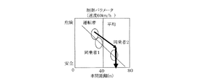
ここで、図15〜図17を参照して、不安を低減するように運転制御を設定する例について説明する。まず、図15は、車間距離を例にして、運転者の危険運転を、安全運転側に変える際の手順を示す。尚、図15〜図17において、横軸は車間距離を示し、縦軸は危険運転の度合(危険度)を示す。図15に示す運転者は、通常の運転においては、車間距離が平均よりも短めで、危険度が高いレベルである。コントローラ12は、データベースからこの運転者のデータを読み込むことで、運転者の危険度を把握する。そして、ユーザ設定が「安全最優先」に設定されている場合には、コントローラ12は、運転者の安全を高めるために車間距離を平均レベル(例えば50m)に増加させるようにする(図7のステップS1060参照)。そのために、コントローラ12は、車間制御ECU8及び第1走行制御ECU9に、車速が例えば60km/hの走行にて、車間距離を例えば50mに設定する指示データ(走行制御パラメータ)を送信する(図7のステップS1070参照)。
Here, with reference to FIGS. 15-17, the example which sets driving control so that anxiety may be reduced is demonstrated. First, FIG. 15 illustrates a procedure for changing the dangerous driving of the driver to the safe driving side, taking the inter-vehicle distance as an example. In FIGS. 15 to 17, the horizontal axis indicates the inter-vehicle distance, and the vertical axis indicates the degree of dangerous driving (risk degree). In the case of the driver shown in FIG. 15, in normal driving, the inter-vehicle distance is shorter than the average, and the danger level is high. The
また、図16は、車間距離を例にして、運転者と同乗者の両方について、車間距離に関する不安を除くための手順を示す。この図16に示す例では、運転者は、車間距離が短くても不安を感じないが、同乗者は車間距離が平均以上ないと不安を感じていることを示している。ここで、ユーザ設定が「安全最優先」に設定されていると、同乗者が不安を持たない車間距離を車間距離の設定値として用いる(図7のステップS1060参照)。そして、コントローラ12は、車間制御ECU8及び第1走行制御ECU9に、車速が例えば60km/hの走行にて、車間距離を例えば50mに設定する指示データ(走行制御パラメータ)を送信する(図7のステップS1070参照)。
Further, FIG. 16 illustrates a procedure for removing anxiety about the inter-vehicle distance for both the driver and the passenger, taking the inter-vehicle distance as an example. In the example shown in FIG. 16, the driver does not feel anxious even if the inter-vehicle distance is short, but shows that the passenger feels anxious if the inter-vehicle distance is not longer than the average. Here, if the user setting is set to “safety first”, the inter-vehicle distance at which the passenger does not have anxiety is used as the set value of the inter-vehicle distance (see step S1060 in FIG. 7). Then, the
また、図17は、運転者と2人の同乗者がいる場合、即ち、合計3人の搭乗者が存在する場合について、車間距離に関する不安を除くための手順を示す。この図17に示す例では、運転者及び同乗者のうちの一人は、車間距離が短くても不安を感じないが、同乗者のうちの他の一人は、車間距離が平均以上ないと不安を感じていることを示している。ここで、ユーザ設定が「安全最優先」に設定されていると、上記他の一人の同乗者が不安を持たない車間距離を車間距離の設定値として用いる。即ち、同乗者が2人いる場合、もっとも車間距離の大きい値を好む同乗者の車間距離の値が選択される(図7のステップS1060参照)。そして、コントローラ12は、車間制御ECU8及び第1走行制御ECU9に、車速が例えば60km/hの走行にて、車間距離を例えば60mに設定する指示データ(走行制御パラメータ)を送信する(図7のステップS1070参照)。
Further, FIG. 17 shows a procedure for removing the anxiety about the distance between the vehicle and the case where there are a total of three passengers when there are a driver and two fellow passengers. In the example shown in FIG. 17, one of the driver and the passenger does not feel anxious even if the distance between the vehicles is short, but the other one of the passengers feels uneasy if the distance between the vehicles is not more than the average. Indicates that you are feeling. Here, when the user setting is set to “safety first”, the inter-vehicle distance with which the other fellow passenger does not have anxiety is used as the set value of the inter-vehicle distance. That is, when there are two passengers, the value of the inter-vehicle distance of the passenger who prefers the largest value of the inter-vehicle distance is selected (see step S1060 in FIG. 7). Then, the
一方、図7のステップS1040において、ユーザ設定が安全最優先でない場合には、「NO」へ進み、ステップS1080へ進み、ユーザ設定が到着時刻優先であるか否かを判断する。ここで、ユーザ設定が到着時刻優先である場合には、「YES」へ進み、ステップS1090へ進み、到着時刻優先の場合でも、安全走行条件を確保して、短時間で目的地に到着する走行条件を選ぶ。尚、到着時刻優先の場合には、高速走行車両に追随して走行することを選択設定できるとしている。 On the other hand, if it is determined in step S1040 in FIG. 7 that the user setting is not the safety top priority, the process proceeds to "NO" and proceeds to step S1080 to determine whether the user setting is arrival time priority. Here, if the user setting is arrival time priority, the process proceeds to "YES", proceeds to step S1090, and secure travel conditions are secured even in the case of arrival time priority, and travel to arrive at the destination in a short time Choose the condition. In the case of prioritizing the arrival time, it is possible to select and set traveling according to the high-speed traveling vehicle.
次に、図18及び図19を参照して、安全最優先でない場合において不安を低減するように運転制御を設定する例について説明する。尚、図18、図19において、横軸は車間距離を示し、縦軸は危険運転の度合(危険度)を示す。図18は、運転者及び同乗者がともに、車間距離が平均以下でも不安を感じない場合の例である。このような場合でも、コントローラ12は、ユーザの安全を確保できる最短車間距離距離を設定する(図7のステップS1090参照)。この車間距離は、平均的な運転者の車間距離よりは短い。この場合、ユーザの不安が起きない限度まで車間距離を短縮するような設定はしない。
Next, with reference to FIGS. 18 and 19, an example will be described in which the operation control is set to reduce anxiety in the case where safety is not the first priority. In FIG. 18 and FIG. 19, the horizontal axis indicates the inter-vehicle distance, and the vertical axis indicates the degree of dangerous driving (risk degree). FIG. 18 shows an example in which both the driver and the passenger do not feel uneasy even if the inter-vehicle distance is less than the average. Even in such a case, the
また、図19は、運転者は車間距離が短くても不安を感じないが、同乗者は車間距離が平均距離以上確保されていないと不安を感じる場合の例である。このように到着時刻優先の場合(特に緊急時の場合など)には、運転者が不安を感じなければ、同乗者の不安が起きることをある程度認めて、走行制御を行うことが可能である(図7のステップS1090参照)。その場合、同乗車が不安を感じる車間距離を安全確保車間距離に設定して、走行制御することが好ましい。このように走行制御した場合には、同乗者から検知される不安感情の計測値は、走行制御に反映されないようにする。この場合、コントローラ12は、車間制御ECU8及び第1走行制御ECU9に、車速が例えば60km/hの走行にて、車間距離を例えば50mに設定する指示データ(走行制御パラメータ)を送信する(図7のステップS1060及びステップS1070参照)。そして、同乗者の不安データは車間距離制御に反映しないように制御する。
Further, FIG. 19 is an example of a case where the driver does not feel anxiety even if the inter-vehicle distance is short, but the passenger feels uneasy that the inter-vehicle distance is not secured more than the average distance. As described above, when priority is given to the arrival time (in particular, in the case of an emergency, etc.), if the driver does not feel anxiety, it is possible to perform traveling control while recognizing that anxiety of the passenger occurs to some extent Refer to step S1090 in FIG. In such a case, it is preferable to control travel by setting the inter-vehicle distance where the same vehicle feels uneasy as the inter-vehicle distance. When travel control is performed in this manner, the measured value of anxiety detected from the passenger is not reflected in travel control. In this case, the
一方、ステップS1080において、その他のユーザ設定条件が設定されている場合には、「NO」へ進み、ステップS1100へ進み、その他のユーザ設定条件を考慮して走行条件を決定するようになっている。 On the other hand, if another user setting condition is set in step S1080, the process proceeds to "NO", proceeds to step S1100, and the driving condition is determined in consideration of the other user setting condition. .
ここで、図13及び図14は、運転者及び同乗者の特性データ(感情データ)の一例を示す図である。まず、運転者の特性データについて、図13を参照して説明する。運転者の特性データとして、まず、運転者のプロパティ(運転の傾向、受容できる範囲など)が記憶されている。この運転者のプロパティには、運転者の氏名と、運転時の特性値とがある。運転時の特性値としては、車間距離において、例えば60km/h走行時の前方車間距離が例えば40m(平均値よりも20m短い)、側方(左右)車間距離が例えば1.0m(通常は0.8mで不安を感じる)、例えば40km/h走行時の前方車間距離が例えば10m(平均値よりも10m短い)、側方(左右)車間距離が例えば1m(通常は0.8m間隔で不安を感じる)というデータが記憶されている。また、曲線道路の走り方において、運転者は、右カーブでは車線中央を走行し、左カーブでは車線中央から左より例えば50cm(内側走行)を走行する、などの運転者の特性値が記憶されている。更に、その他の特性データとして、ふらつき、振動、音などに対し、運転者がどのような状態で不安を感じるかのデータが記憶されている。 Here, FIG. 13 and FIG. 14 are diagrams showing an example of the characteristic data (emotion data) of the driver and the passenger. First, the characteristic data of the driver will be described with reference to FIG. As the characteristic data of the driver, first, the driver's properties (driving tendency, acceptable range, etc.) are stored. The driver's properties include the driver's name and a characteristic value at the time of driving. As the characteristic value at the time of driving, for example, in the inter-vehicle distance, the front inter-vehicle distance at the time of 60 km / h traveling is, for example, 40 m (20 m shorter than the average value), and the side (left and right) inter-vehicle distance is Anxiety at 8m)) For example, the distance between vehicles at the time of 40km / h traveling is 10m (10m shorter than the average value), and the distance between side (left and right) is for example 1m (usually 0.8m) Data is stored. In addition, the driver's characteristic value such as traveling 50 cm (inward traveling) from the left of the lane center from the center of the lane is stored in the left curve when the driver travels along the curved road. ing. Furthermore, as other characteristic data, there are stored data on how the driver feels anxious with respect to wandering, vibration, sound and the like.
また、図14は、同乗者の特性データの一例を示しており、上記した運転者の特性データとほぼ同様のデータが記憶されている。尚、図13及び図14に示すデータは、説明の都合上、テキストが多く含まれるデータであるが、実際はデータフォーマットを決めて、データをコンパクトにして記憶することが望ましい。 FIG. 14 shows an example of the characteristic data of the passenger, and data substantially similar to the above-mentioned characteristic data of the driver is stored. Although the data shown in FIGS. 13 and 14 is data containing a large amount of text for convenience of explanation, it is desirable to determine the data format and store the data in a compact form.
次に、図8のフローチャートを参照して、運転者と同乗者の両方に不安を与えない走行制御の一例について説明する。まず、ステップS1210においては、リアルタイムのユーザの不安を計測する。この処理は、図2のステップS60、即ち、図5に示すサブルーチンを用いて実行する。 Next, with reference to a flowchart of FIG. 8, an example of travel control that does not give anxiety to both the driver and the passenger will be described. First, in step S1210, the user's anxiety in real time is measured. This process is performed using step S60 of FIG. 2, that is, the subroutine shown in FIG.
続いて、ステップS1220へ進み、前記統計値(即ち、図2のステップS50で得られる道路情報からの不安予測データ(学習値)とユーザの走り方に対する不安予測データ(学習値))と、上記ステップS1210で計測された実測値とに基づいて、ユーザの不安あり、あるいは、不安が起きそう、と判定する(図2のステップS70参照)。 Subsequently, the process proceeds to step S1220, and the statistical value (i.e., anxiety prediction data (learning value) from the road information obtained in step S50 of FIG. 2 and anxiety prediction data (learning value) for how the user runs) Based on the measured values measured in step S1210, it is determined that the user is anxious or that anxiety is likely to occur (see step S70 in FIG. 2).
次いで、ステップS1230へ進み、視覚、縦g(gは加速度)、横g、ふらつき(走行位置)、振動、音等に対して、ユーザの不安要素の抽出を行う。この場合、運転者の特性データと同乗者の特性データを比較して解析する。そして、ステップS1240へ進み、運転制御目標値(走行条件)を選択・設定する。続いて、ステップS1250へ進み、運転制御目標値を達成するための運転制御パラメータを選択・設定する処理を行う。この処理は、図7のステップS1060の処理とほぼ同様にして実行する。 Next, proceeding to step S1230, the user's anxiety factor is extracted with respect to vision, vertical g (g is acceleration), horizontal g, wobble (traveling position), vibration, sound and the like. In this case, the driver's characteristic data and the passenger's characteristic data are compared and analyzed. Then, the process proceeds to step S1240, and the operation control target value (traveling condition) is selected and set. Subsequently, the process proceeds to step S1250, and a process of selecting and setting operation control parameters for achieving the operation control target value is performed. This process is executed substantially in the same manner as the process of step S1060 of FIG.
この後、ステップS1260へ進み、運転制御パラメータ(制御範囲と制御目標)を関連するECU(車間制御ECU8、第1走行制御ECU9、第2走行制御ECU10、第3走行制御ECU15等)へ送信する。これにより、送信された運転制御パラメータを使って車両の運転制御が実行される。その後、ステップS1270へ進み、リアルタイムのユーザ不安の計測が行われる。この処理は、図2のステップS60(図4のサブルーチン)の処理を用いて実行することができる。
Thereafter, the process proceeds to step S1260, and the driving control parameter (control range and control target) is transmitted to the associated ECU (for example,
次いで、ステップS1280へ進み、不安計測の結果、ユーザの不安低減効果が有るか否かを判断する。ここで、不安低減効果があれば、「YES」へ進み、ステップS1270へ戻り、運転制御を継続する。一方、ステップS1280にて、不安低減効果が無い場合には、「NO」へ進み、ステップS1250へ進み、運転制御パラメータの変更を行なう。 Next, the process proceeds to step S1280, and as a result of anxiety measurement, it is determined whether there is an anxiety reduction effect of the user. Here, if there is an anxiety reduction effect, the process proceeds to "YES", returns to step S1270, and continues the operation control. On the other hand, if there is no anxiety reduction effect at step S1280, the process proceeds to "NO" and proceeds to step S1250 to change the operation control parameter.
次に、脳活性域計測器23の具体的構成について、図11及び図12を参照して説明する。脳活性域計測器23は、脳内領域状況計測器を構成するものであり、不安を感じたときに活性化する脳の部位の状況を複数の脳波センサ24を用いて計測する。図12は、人が不安(恐怖)を感じた場合に、脳のどの領域が活性化するかを示した図であり、斜線領域が活性化した領域を示す。図12(a)は脳の左半球側を示し、図12(b)は脳の右半球側を示す。
Next, a specific configuration of the brain active
本実施形態では、ユーザが車両に乗ったときに、種々の状況で感ずる不安を計測することを目的にしている。通常の脳波計測では頭部全体にセンサを配置する方法が一般的である。この方法では、多くのセンサが必要になり、トータルの価格が高額になる。そこで、本実施形態では、不安時に活性化する活性域に密着した地点のみに脳波センサ24を配置してセンサ数を減らすと共に、その脳波センサ24の計測値の大小のみで、不安度を計測するように構成した。
In the present embodiment, it is an object to measure anxiety felt in various situations when the user gets on the vehicle. In ordinary electroencephalogram measurement, a method of disposing a sensor on the entire head is common. In this method, many sensors are required, and the total price is high. Therefore, in the present embodiment, the
図12に示すように、不安によって活性化する脳の領域がおおよそわかっているため、その領域の状況を測定するために該当する領域(位置)に密着するように脳波センサ24を複数個、配置するように構成した。脳の活性域に個人差がある場合に備えて、脳波センサ24の配置位置を調整することが可能な構造とした。また、脳波センサ24を取り外して、別の位置に取り付け位置を変更可能なように構成しても良い。
As shown in FIG. 12, since the region of the brain activated by anxiety is roughly known, a plurality of
図11に、脳活性域計測器23の概略構成(イメージ)を示す。図11(a)は脳活性域計測器23を側面から見た図、図11(b)は脳活性域計測器23をほぼ正面から見た図である。脳活性域計測器23は、メッシュ素材からなる半球状部材26と、半球状部材26の内部に脳の活性域に対応した位置に固定された複数の脳波センサ24と、半球状部材26の端部に設けられた頭部装着用の複数の固定用パッド27とを備えている。半球状部材26のメッシュ素材としては、例えば適度な伸び縮みが可能な材料(ゴム材)を用いることが好ましい。また、脳波センサ24の上下左右の位置が容易に移動しないように、半球状部材26の頭頂部にも固定用の固定用パッド27を設けることが好ましい。
FIG. 11 shows a schematic configuration (image) of the brain active
ここで、複数(例えば3個)の脳波センサ24のブロック図を図10に示す。図10に示すように、各脳波センサ24は、活性度検出器30と、記憶手段31と、送受信機32とを備えている。活性度検出器30は、脳が不安を感じたときの血管内の血中酸素濃度の変動、あるいは、脳細胞のイオン授受により発生する微弱電流などを測定することにより、脳の活性域の活性度を検出し、検出した活性度検出信号を送受信機32へ出力する。記憶手段31には、計測する位置情報が記憶されている。送受信機32は、活性度検出器30からの活性度検出信号と、記憶手段31に記憶されている位置情報とを、無線通信機能を用いて車両の走行制御システム1へ送信する。
Here, a block diagram of a plurality of (for example, three)
本実施形態では、脳波センサ24(送受信機32)は、無線通信機能を用いて車両の走行制御システム1からの起動信号を受信すると、活性度検出器30により脳の活性域の状態(活性度)の計測を開始する。計測結果は、即時、送受信機32により車両の走行制御システム1へ送信されるようになっている。また、脳波センサ24は、車両の走行制御システム1から計測の停止命令を受けると、動作を停止し待機状態になる。
In the present embodiment, when the brain wave sensor 24 (transceiver 32) receives the activation signal from the traveling control system 1 of the vehicle using the wireless communication function, the state of the active area of the brain by the activity detector 30 (activity Start the measurement of). The measurement result is immediately transmitted by the
次に、本実施形態の車両の走行制御システム1の動作中のイメージを、図20〜図22に示す。図20は、車両が自動運転中で、これから、不安解消モードが動作する地点に近づくことを示した表示イメージ(表示装置17の表示画面の例)である。図20において、三角形が車両の現在位置を示し、「自動運転中」と「不安解消モード作動予定地点」のメッセージが表示されている。 Next, the image in process of the traveling control system 1 of the vehicle of this embodiment is shown in FIGS. 20-22. FIG. 20 is a display image (an example of a display screen of the display device 17) showing that the vehicle is in automatic driving and the point at which the anxiety resolution mode operates is now approached. In FIG. 20, a triangle indicates the current position of the vehicle, and the messages of "during automatic driving" and "anxiety cancellation mode operation scheduled point" are displayed.
図21は、不安解消モードが動作中であることを示した表示イメージである。図21において、三角形が車両の現在位置を示し、「不安解消モードシステム動作中」と「不安解消モード 左急カーブ用走行制御 動作中」のメッセージが表示されている。図22は、手動運転の場合において、ユーザの不安状態を報知することを示した表示イメージである。図22において、三角形が車両の現在位置を示し、「不安状態報知」と「同乗者が不安を感じています」のメッセージが表示されている。これらの表示イメージは、車両の走行制御システム1の動作をユーザに確認させるためになされる表示である。ユーザが、これらの表示を不要であると思えば、走行制御システム1の動作に関する表示を行わないようにする設定も可能なように構成されている。 FIG. 21 is a display image showing that the anxiety cancellation mode is in operation. In FIG. 21, triangles indicate the current position of the vehicle, and the messages “during anxiety cancellation mode system in operation” and “anxiety cancellation mode in running control for left sharp curve operation in operation” are displayed. FIG. 22 is a display image showing notification of the user's anxiety state in the case of manual operation. In FIG. 22, a triangle indicates the current position of the vehicle, and the messages “anxiety state notification” and “the passenger is feeling anxious” are displayed. These display images are displays made to make the user confirm the operation of the travel control system 1 of the vehicle. If the user thinks that these displays are unnecessary, it is configured to be able to set so as not to display the operation control of the traveling control system 1.
次に、図23〜図26を参照して、図4のステップS660の処理(乗員の過去データ(記憶されている平常時データ)と計測データとの比較処理の例について説明する。図23〜図26は、脳の活性度の変化を測定した例であり、図23は脳の右半球の後部(R-Rear)の例であり、図24は脳の右半球の底の部分(R-Bottom)の例であり、図25は脳の左半球の前方部(L-Front)の例であり、図26は脳の左半球の後部(L-Rear)の例である。各図において、縦軸は活性度計測値(脳波センサ24から出力される計測信号)の電圧Eを示し、横軸は時間を示す。平常時レベルでは、活性度レベルが低いため、活性度の測定電圧は低い。何かの不安を励起する刺激が時刻0にて起きると、その刺激により脳の該当部位の電圧が上昇する。時刻0から設定時間Δtが経過したときに、脳の活性度を示す電圧Eを測定する。この計測により、外部刺激に対して脳活動の活性化の度合いが判定できる。本実施形態では、脳の活性基準値を設定しており、図27(a)に示すように、設定時間Δt(秒)の間にΔEa(V)以上上昇したとき、活性基準値を超えたと判定する。尚、この判定処理は、電圧Eの立ち上り及び立下り時に実施する。
Next, an example of the process of comparing the process of step S660 of FIG. 4 (the occupant's past data (stored normal data) and the measurement data) will be described with reference to FIGS. FIG. 26 shows an example of measurement of changes in brain activity, FIG. 23 shows an example of the rear (R-Rear) of the right hemisphere of the brain, and FIG. 24 shows the bottom of the right hemisphere of the brain (R- Fig. 25 shows an example of the bottom (L-Front) of the left hemisphere of the brain and Fig. 26 shows an example of the rear (L-Rear) of the left hemisphere of the brain. The vertical axis shows the voltage E of the activity measurement value (measurement signal output from the electroencephalogram sensor 24) and the horizontal axis shows time In the normal level, since the activity level is low, the measurement voltage of the activity is low. When a stimulus that excites anxiety occurs at
また、スパイク状のパルスノイズを除くために、図27(b)に示すように、脳の活性度を示す電圧Eが最大になってから平常時レベルに戻る時間(立下り時間)Δt2を測定し、Δt2がΔtよりも小さい場合、活性基準値を超えたとは判断しない。図27(b)において、計測信号A1は、電圧の立ち上がりの高さは活性基準値の高さΔEaを超えているが、立下り時間Δt2がΔtよりも短いため、活性基準値を超えたとは判断しない。
In addition, as shown in FIG. 27 (b), in order to remove spiked pulse noise, the time (falling time) Δt2 at which the voltage E indicating the activity of the brain returns to the normal level after reaching the maximum is measured. If
ここで、脳波センサ24から出力される計測信号の電圧Eの平常時レベル(図23ないし図27参照)について、説明する。まず、ユーザが車両に搭乗した直後に計測した脳活性度(計測信号の電圧)Eの測定値の平均値を、平常時レベルとすることが好ましい。このように平常時レベルを定義すると、平常時レベルは、車両搭乗時の脳活性度の状態が統計的に把握されたデータになる。
Here, the normal level (see FIGS. 23 to 27) of the voltage E of the measurement signal output from the
尚、車両以外の家や病院などのユーザの脳波計測が可能な場所において、ユーザが安定した条件で計測した脳活性度Eの測定値の平均値を、安静時平常時レベルと定義することも好ましい。この場合、車両に搭乗するまでに起きるユーザの不安感、わくわく感などによりユーザの脳活性度が変化するため、その影響を別途計測して、把握する必要がある。このため、平常時レベルは、安静時平常時レベルに搭乗時感情レベルを加算したデータになる。 In addition, it is also possible to define the average value of the measurement values of brain activity E measured under stable conditions by the user as the resting normal level in places where brain waves of the user other than the vehicle can be measured. preferable. In this case, since the brain activity of the user changes due to the user's feeling of anxiety or excitement occurring before getting on the vehicle, it is necessary to separately measure and grasp the influence. Therefore, the normal level is data obtained by adding the emotion level upon boarding to the resting normal level.
さて、車両において、適切な安全走行制御が行われないと、運転者または同乗者に継続的に不安を起こす刺激が与えられる(図23ないし図26において太い実線参照)。刺激が継続すると、脳の該当部位の活性度(脳の活性度を示す電圧E)が、ユーザが不安を感じたことを判定するために設定した閾値(不安基準値)を超えることから、ユーザは望まない不安を感じたと判定される。図23において、閾値と書かれている電圧値は、不安判定に使われる電圧(不安基準値)である。この場合、その不安によって、さまざまな身体ストレス反応が誘起される。 Now, in the vehicle, if appropriate safe travel control is not performed, the driver or the passenger is continuously stimulated to cause anxiety (see thick solid lines in FIGS. 23 to 26). If the stimulation continues, the activity of the corresponding part of the brain (voltage E indicating the activity of the brain) exceeds the threshold (anxiety reference value) set to determine that the user felt anxiety. Is judged to have felt anxious anxiety. In FIG. 23, a voltage value written as a threshold is a voltage (anxiety reference value) used for anxiety determination. In this case, the anxiety induces various physical stress responses.
本実施形態では、脳の不安を感ずる各部位の活性度を、種々の走行条件で測定しておき、不安が誘起される走行条件を学習して、次回、同様な不安を励起する走行条件になりそうな場合、事前に走行パラメータを調整して、不安がおきない走行条件に制御する。これにより、時刻0から単位時間Δtにおける活性度電圧の立ち上がりから、脳の各部位の活性度を予測する。例えば、走行条件1で、単位時間あたり立ち上がり電圧ΔE1が得られ、走行条件2で、単位時間あたり立ち上がり電圧ΔE2が得られたとすると、走行条件2の方が、不安を励起しやすいという結果が得られる。その学習値に基づいて、次に走行条件2が起きると予想できると、走行条件2の走行にならないようにする走行制御を確実に実行することで、ユーザの不安を抑制することができる。
In this embodiment, the activity of each part that feels anxiety in the brain is measured under various running conditions, and the running conditions under which anxiety is induced are learned, and the running conditions under which the same anxiety is excited next time. If it is likely to occur, adjust the driving parameters in advance to control the driving conditions so that you do not feel uneasy. Thus, the activity of each part of the brain is predicted from the rise of the activity voltage from
図23〜図26は、脳の不安を感じる4つの部位について、速度が例えば60km/h、左カーブ(例えばR=100m))の走行条件において、走行制御を行った場合と走行制御を行わない場合のシミュレーション結果を示す。脳の不安を感ずる各部位において、立ち上がり電圧のパターンが異なる。脳の活性域を測定する複数の脳波センサ24のうちのいずれかが不調(故障)であっても、各部位の活性特性を記録しておけば、いずれか1つの脳波センサ24の測定結果より、ユーザの不安を計測することができる。
23 to FIG. 26 show the case where the running control is performed and the running control is not performed under the running conditions of, for example, the speed of 60 km / h and the left curve (for example, R = 100 m) for four parts that feel anxiety in the brain. The simulation results of the case are shown. The pattern of the rising voltage is different in each part that feels anxiety of the brain. Even if any of the plurality of
上記した構成の本実施形態によれば、運転者生体情報検知器3により測定したユーザの不安度の測定結果によりユーザが不安であると判定されたときに、その不安の元になる不安要因を、車両の走行状況に対するユーザの特性データに基づいて判定し、この判定された不安要因に基づいて車両の走行制御の制御度合い(制御パラメータ)を調整することにより、ユーザの不安が小さくなるように車両の走行制御を変更するように構成したので、自動運転による走行制御を行っても、ユーザが不安を感じることを極力防止できる。
According to the above-described embodiment, when it is determined that the user is anxious by the measurement result of the user's anxiety measured by the driver
また、本実施形態では、運転者生体情報検知器3の脳活性域計測器23により、ユーザの感情の変化を示す複数の脳内領域の状況として例えば活性度を直接計測するように構成したので、ユーザの感情、特には不安の有無を正確に判定することができる。更に、運転者生体情報検知器3は、ユーザの心拍数や血圧を計測するセンサを備え、心拍数や血圧の計測結果によってユーザの感情(不安)を判定するように構成したので、ユーザの感情の変化を素早く判定することができる。
Further, in the present embodiment, the brain activity
また、本実施形態では、車両の走行制御を変更する前に、運転者に報知を行うように構成したので、車両の走行制御が変更されることを運転者は明確に認識することができる。そして、本実施形態では、車両の走行制御を変更した後、ユーザの不安度を計測し、計測結果に基づいてユーザの不安度の変化を求めると共に、ユーザの不安が解消していないときには、その不安の元になる不安要因を判定し、この判定された不安要因に基づいて車両の走行制御の制御度合いを再調整してから、車両の走行制御を実行するように構成したので、ユーザが不安を感じることをより一層防止できる。 Further, in the present embodiment, the driver is notified before the travel control of the vehicle is changed, so that the driver can clearly recognize that the travel control of the vehicle is changed. Then, in the present embodiment, after changing the traveling control of the vehicle, the user's anxiety is measured, and a change in the user's anxiety is obtained based on the measurement result, and when the user's anxiety is not resolved, An anxiety factor that is the source of anxiety is determined, and the degree of control of the traveling control of the vehicle is readjusted based on the determined anxiety factor, and then the traveling control of the vehicle is executed, so that the user is anxious. Can be further prevented.
また、本実施形態では、カメラ5により撮影した車両の周辺画像情報に基づいて道路上の車幅方向の走行位置を検知し、レーダ7により前方の車両との車間距離を検知し、ユーザが不安を感じる範囲における車両の有無を判定し、ユーザが周辺車両との距離に不安を感じていると判定した場合、ユーザの不安が低減されるように車両の位置を調整するように構成したので、ユーザが不安を感じることをより一層防止できる。
Further, in the present embodiment, the traveling position in the vehicle width direction on the road is detected based on the peripheral image information of the vehicle captured by the
また、本実施形態では、曲線道路に進入する際において、車両の走行速度による遠心力がユーザの不安を引き起こすと判定した場合、減速して曲線道路に進入するように走行制御するように構成したので、曲線道路を自動運転により走行する場合に、ユーザが不安を感じることを極力防止できる。 Further, in the present embodiment, when it is determined that the centrifugal force due to the traveling speed of the vehicle causes the user's anxiety when entering a curved road, the traveling control is performed so as to decelerate and enter the curved road. Therefore, when traveling on a curved road by automatic driving, it is possible to prevent the user from feeling uneasy as much as possible.
また、本実施形態では、運転者が手動運転中に、同乗者が不安を感じていることを車両が検知した場合に、同乗者が不安を感じていることを運転者に報知するように構成したので、同乗者が不安を感じないように運転者は手動運転を補正する(運転者の運転技量を向上させる)ことが可能になる。これにより、同乗者の運転者に対する不安を低減することができる。 Further, in the present embodiment, when the vehicle detects that the passenger feels anxiety while driving manually, the driver is notified that the passenger feels anxiety Thus, the driver can correct the manual driving (improve the driver's driving skill) so that the passenger does not feel anxious. This can reduce the anxiety of the passenger on the driver.
尚、本実施形態では、脳活性域計測器23の固定用パッド27を頭部装着用部材として用いたが、これに代えて、マジックテープ(登録商標)や、ヘアピン状のものや、小型の櫛状のものなどを用いても良い。また、脳波を計測する別の方法として、三角測量的な計測を行う構成の場合には、脳波センサ24を脳の活性域へ密着させる必要はなく、活性域の情報が得やすい位置に脳波センサ24を配置するように構成すれば良い。このように構成した場合、前記した密着タイプに比べると、測定精度が低下する。尚、本実施形態では、脳波センサ24を脳の活性域に対応した位置に配設するように構成したが、これに代えて、脳波センサ24の配設個数は多くなるが、脳の全領域に均一に配設するように構成しても良い。
In the present embodiment, the fixing
また、本実施形態では、脳内領域の状況として、脳波を検知するように構成したが、これに代えて、脳血流を検知するように構成しても良い。脳血流の計測は、例えば人の頭に接触するウェアラブルな近赤外分光計測装置を用いることが可能である。また、ユーザの上部(車両の天井部)に、脳で生成される微弱な電磁波を計測できるセンサ(例えばパラボラアンテナ)を設けて、脳波の代わりに脳磁場を計測するように構成しても良い。この構成の場合、脳で生成する微弱な電磁波を正確に計測するために、脳以外から頭の部分へ到達する電磁波ノイズを遮蔽する遮蔽体を設けるように構成しても良い。例えば、車室内と車両の電源コントロール用ECUや高周波の通信ラインを分離したり、脳波検知タイミングに同期して、車室内の無線通信機器を一時的に停止させたりするように制御しても良い。 Further, in the present embodiment, an electroencephalogram is detected as a condition of the in-brain region, but instead, it may be configured to detect a cerebral blood flow. For measurement of cerebral blood flow, it is possible to use, for example, a wearable near-infrared spectrometer which contacts a human head. In addition, a sensor (for example, a parabolic antenna) capable of measuring weak electromagnetic waves generated by the brain may be provided on the upper part of the user (the ceiling of the vehicle) to measure the brain magnetic field instead of the brain waves. . In the case of this configuration, in order to accurately measure the weak electromagnetic waves generated by the brain, a shield may be provided to shield electromagnetic wave noise that reaches the head part from other than the brain. For example, control may be performed to separate a power supply control ECU for a vehicle interior and a vehicle and a high-frequency communication line, or to temporarily stop wireless communication devices in the vehicle compartment in synchronization with brain wave detection timing. .
図28ないし図32は、本発明の第2実施形態を示すものであり、第1実施形態と同一構成には、同一符号を付している。上記第1実施形態では、ユーザ(運転者や搭乗者)が不安であるか否かを判定する場合、脳活性域計測器23の脳波センサ24により測定された計測値が所定の閾値(不安基準値)よりも大きくなったときに、ユーザが不安であると判定するようにしている。
FIGS. 28 to 32 show a second embodiment of the present invention, in which the same reference numerals as in the first embodiment denote the same parts as in the first embodiment. In the first embodiment, when it is determined whether or not the user (driver or passenger) is uneasy, the measured value measured by the
これに対して、第2実施形態では、ユーザが車両に搭乗したときに、脳活性域計測器23(脳波センサ24)によりユーザの不安度を測定し、この測定結果を搭乗時平常値として記憶する。また、車両の走行開始後、ユーザに力(加速度)のかからない状態のときに、脳活性域計測器23(脳波センサ24)によりユーザの不安度を測定し、この測定結果を走行時平常値として記憶する。そして、車両の走行中において、ユーザに力(加速度)が加わったときに、脳活性域計測器23によりユーザの不安度測定を行う際には、脳活性域計測器23(脳波センサ24)によりユーザの不安度を測定し、この測定結果を、走行時平常値(搭乗時平常値)と比べて、予め設定した設定値以上の違い(差)がある場合に、ユーザが不安であると判定する。以下、第2実施形態について具体的に説明する。
On the other hand, in the second embodiment, when the user gets on the vehicle, the degree of anxiety of the user is measured by the brain activity area measuring device 23 (brain wave sensor 24), and the measurement result is stored as a boarding normal value. Do. In addition, after starting the running of the vehicle, when the user does not apply force (acceleration), the user's anxiety is measured by the brain activity area measuring instrument 23 (brain wave sensor 24), and this measurement result is taken as the running normal value. Remember. Then, when a force (acceleration) is applied to the user while the vehicle is traveling, when the user's anxiety is measured by the brain active
図28は、第1実施形態の図2のフローチャートに代わるものであり、第2実施形態の走行制御システムのメイン制御のフローチャートである。この図28の制御は、例えば車両のイグニッションスイッチがオンされると、スタートする。まず、ステップS02において、システムが起動される。続いて、ステップS04へ進み、脳活性域計測器23(脳波センサ24)によりユーザが車両に搭乗したときのユーザの不安度(の平常値)を測定し、この測定結果を搭乗時平常値として記憶する。この不安測定処理の具体的内容については、図29に示すサブルーチンのフローチャートを参照して、説明する。尚、図29のフローチャートは、第1実施形態の図5のフローチャートを流用して作成されている。図29(a)のフローチャートは、走行制御システム1のユーザの不安測定処理の制御内容を示す。図29(b)のフローチャートは、脳活性域計測器23の脳波センサ24の制御内容を示す。
FIG. 28 is a flowchart of the main control of the traveling control system of the second embodiment, replacing the flowchart of FIG. 2 of the first embodiment. The control of FIG. 28 starts, for example, when the ignition switch of the vehicle is turned on. First, in step S02, the system is activated. Subsequently, the process proceeds to step S04, and the user's anxiety level (normal value) when the user gets on the vehicle is measured by the brain activity area measuring device 23 (brain wave sensor 24), and this measurement result is taken as the normal value at boarding time. Remember. The specific content of the anxiety measurement process will be described with reference to the flowchart of the subroutine shown in FIG. The flowchart of FIG. 29 is created using the flowchart of FIG. 5 of the first embodiment. The flowchart of FIG. 29A shows the control contents of the user's anxiety measurement process of the traveling control system 1. The flowchart of FIG. 29 (b) shows the control contents of the
まず、図29(a)のステップS810では、車両の走行制御システム1は、不安度合いの測定を開始し、脳活性域計測器23の脳波センサ24に電力供給し、計測開始命令を出力して、脳波センサ24を起動させる。これを受けて脳波センサ24は、図29(b)のステップS910において、起動する。そして、脳波センサ24は、起動すると、起動応答を走行制御システム1へ送信する。続いて、ステップS920へ進み、脳波センサ24は、計測を開始する。次いで、ステップS930へ進み、脳波センサ24は、計測結果を走行制御システム1(運転者状況判定器4)へ送信する。そして、脳波センサ24は、ステップS940へ進み、待機状態となる、または、動作を停止する。
First, at step S810 in FIG. 29A, the traveling control system 1 of the vehicle starts measurement of the degree of anxiety, supplies power to the
一方、走行制御システム1側では、図29(a)のステップS820へ進み、脳活性域計測器23の各設置位置の複数の脳波センサ24の計測値を取得する。続いて、ステップS822へ進み、ユーザが車両に搭乗したときであるか否か(即ち、車両が走行開始していないか否か)を判断する。ここで、搭乗時であるときには(ステップS822にて「YES」)、ステップS824へ進み、上記計測値を搭乗時平常値として記憶手段13に記憶する。尚、図28のステップS04で本サブルーチンが呼び出されたときには、上記ステップS824の処理が実行される。
On the other hand, on the traveling control system 1 side, the process proceeds to step S820 in FIG. 29A, and measurement values of the plurality of
また、上記ステップS822において、搭乗時でないとき、即ち、車両が走行開始した後であるときには(「NO」)、ステップS826へ進み、上記計測値を走行時平常値として記憶手段13に記憶する。尚、図28のステップS34(後述する)で本サブルーチンが呼び出されたときには、上記ステップS826の処理が実行される。
In step S822, when it is not boarding, that is, after the vehicle has started traveling ("NO"), the process proceeds to step S826, and the measured value is stored in the
この後、図28のステップS10へ進み、車両が走行中であるか否かを判断する。ここで、走行中でないときには(ステップS10にて「NO」)、ステップS10の判断処理を繰り返す。上記ステップS10において、車両が走行中であると判断されると(「YES」)、ステップS30へ進み、ユーザ(運転者または同乗者)の認識処理が実行される。このユーザの認識処理は、第1実施形態(図3に示すサブルーチンにより)と同様にして実行される。 Thereafter, the process proceeds to step S10 in FIG. 28 to determine whether the vehicle is traveling. Here, when the vehicle is not traveling ("NO" in step S10), the determination process of step S10 is repeated. If it is determined in step S10 that the vehicle is traveling ("YES"), the process proceeds to step S30, and recognition processing of the user (driver or passenger) is performed. This user recognition process is performed in the same manner as in the first embodiment (by the subroutine shown in FIG. 3).
次いで、ステップS32へ進み、車両の走行開始後、車両(ユーザ)に作用する加速度が予め設定された設定値よりも小さいか否かを判断する。ここで、加速度が予め設定された設定値よりも小さいとき、即ち、ユーザに対して力(加速度)のかからない状態であるときには(ステップS32にて「YES」)、ステップS34へ進む。このステップS34では、車両の走行中において、脳活性域計測器23(脳波センサ24)によりユーザに対して力のかからない状態である場合のユーザの不安度(の平常値)を測定し、この測定結果を走行時平常値として記憶する。この不安測定処理は、上述した図29に示すサブルーチンによって実行される。この場合、上述したように、図29のステップS822にて「NO」へ進み、ステップS826が実行されるようになっている。 Next, the process proceeds to step S32, and after the start of traveling of the vehicle, it is determined whether the acceleration acting on the vehicle (user) is smaller than a preset setting value. Here, when the acceleration is smaller than the preset set value, that is, when the force (acceleration) is not applied to the user ("YES" in step S32), the process proceeds to step S34. In this step S34, while the vehicle is traveling, the brain active area measuring device 23 (electroencephalogram sensor 24) measures the user's anxiety (normal value) when no force is applied to the user, and this measurement is performed. The result is stored as a driving normal value. This anxiety measurement process is executed by the subroutine shown in FIG. 29 described above. In this case, as described above, the process proceeds to "NO" in step S822 in FIG. 29, and step S826 is performed.
この後は、第1実施形態と同様にして、ステップS40およびステップS50が実行される。次いで、ステップS65へ進み、車両の走行制御を行っている間に、ユーザの不安検知と不安判定を行う。この不安検知/不安判定の処理については、図30に示すサブルーチンのフローチャートを参照して、説明する。尚、図30のフローチャートは、第1実施形態の図5のフローチャートを流用して作成されている。図30(a)のフローチャートは、走行制御システム1のユーザの不安度合いの判定処理の制御内容を示す。図30(b)のフローチャートは、脳活性域計測器23の脳波センサ24の制御内容を示す。
After this, steps S40 and S50 are executed as in the first embodiment. Next, the process proceeds to step S65, and while the travel control of the vehicle is being performed, the user's anxiety detection and anxiety determination are performed. The process of the anxiety detection / anxiety determination will be described with reference to the flowchart of the subroutine shown in FIG. The flowchart of FIG. 30 is created by diverting the flowchart of FIG. 5 of the first embodiment. The flowchart of FIG. 30A shows the control contents of the process of determining the degree of anxiety of the user of the traveling control system 1. The flow chart of FIG. 30 (b) shows the control contents of the
第2実施形態においても、図30(a)のステップS810からステップS850までの処理、並びに、図30(b)のステップS910からステップS940までの処理は、第1実施形態と同様にして、実行する。 Also in the second embodiment, the processing from step S810 to step S850 in FIG. 30A and the processing from step S910 to step S940 in FIG. 30B are performed in the same manner as in the first embodiment. Do.
そして、走行制御システム1側において、活性センサ数を記録する(ステップS840)と共に、各脳波センサ24の計測値を読み取り、記憶した(ステップS850)後は、ステップS865へ進む。このステップS865においては、複数の脳波センサ24の計測値を、記憶している走行時平常値と比べて、予め設定した設定値以上の違い(差)があるか否かを判断すると共に、設定値以上の差がある脳波センサ24の数が第2設定数を超えているか否かを判断する。ここで、脳波センサ24の計測値を走行時平常値と比べて、設定値以上の違い(差)があるか否かを判断するに際しては、例えば、第1実施形態で用いた閾値(不安基準値)を走行時平常値に基づいてシフトさせる制御を実行する。
Then, on the traveling control system 1 side, the number of active sensors is recorded (step S 840), and the measurement values of each
具体的には、図31に示すように、第1実施形態で用いた閾値を閾値Et1とし、第2実施形態で用いるシフトさせた閾値を閾値Et2とする。ここで、平常時レベルをE0とし、脳活性度の増分(閾値設定用)をΔEtとし、走行時平常値をErとし、走行時平常値Erと平常時レベルE0との差をバイアスΔEbとすると、
Et1=E0+ΔEt
Et2=E0+ΔEb+ΔEt
となる。即ち、第2実施形態で用いる閾値Et2は、第1実施形態で用いた閾値Et1よりもバイアスΔEbだけシフトされている。上記ステップS865では、閾値Et2を上述したようにして計算した後、この閾値Et2を超えている脳波センサ24の数が第2設定数を超えているか否かを判断する。尚、閾値Et2の式において、ΔEt(脳活性度の増分)について、第1実施形態と同じ値を使用したが、これに代えて、バイアスΔEbの値に応じて変動する変数αを上記ΔEtに乗じたもの、即ち、αΔEtを上記ΔEtに代えて使用することも好ましい。
Specifically, as shown in FIG. 31, the threshold used in the first embodiment is a threshold Et1, and the shifted threshold used in the second embodiment is a threshold Et2. Here, it is assumed that the normal level is E0, the increment of brain activity (for threshold setting) is ΔEt, the running normal value is Er, and the difference between the running normal value Er and the normal level E0 is bias ΔEb. ,
Et1 = E0 + ΔEt
Et2 = E0 + ΔEb + ΔEt
It becomes. That is, the threshold Et2 used in the second embodiment is shifted by the bias ΔEb more than the threshold Et1 used in the first embodiment. In step S865 described above, after the threshold Et2 is calculated as described above, it is determined whether the number of
そして、ステップS865において、閾値Et2を超えている脳波センサ24の数が第2設定数を超えたときには(「YES」)、ステップS870へ進み、ユーザ(計測対象者)は不安状態であると判定する。一方、上記ステップS865において、第2の設定値以上の差がある脳波センサ24の数が第2設定数を超えていないときには(「NO」)、ステップS880へ進み、ユーザ(計測対象者)は不安状態に達していないと判定する。
Then, in step S865, when the number of
この後は、図28のステップS70へ進み、ユーザが不安を感じているか否かを判断する。ここで、ユーザの不安ありと判定されると(ステップS70にて「YES」)、ステップS80へ進み、第1実施形態と同様にして、ユーザの不安を低減するための車両の走行制御が行われる。そして、ステップS90へ進み、第1実施形態と同様にして、制御の変更に付随して制御状況の報知が必要な場合、制御状況報知を行う。 After this, the process proceeds to step S70 of FIG. 28, and it is determined whether the user feels anxiety. Here, if it is determined that the user's anxiety is present ("YES" in step S70), the process proceeds to step S80, and, similar to the first embodiment, vehicle travel control for reducing the user's anxiety is performed. It will be. Then, the process proceeds to step S90, and in the same manner as in the first embodiment, when notification of the control condition is required accompanying the change of control, the control condition is notified.
次に、ステップS105へ進み、車両のイグニッションスイッチがオンであるか否かを判断する。ここで、イグニッションスイッチがオンであれば(ステップS105にて「YES」)、ステップS32へ戻り、上述した処理を繰り返す。この場合、車両の走行中において、ユーザに対して力のかからない状態であるときには、ステップS34の処理が設定時間毎に実行されて、走行時平常値が逐次(設定時間毎に)記憶されて蓄積されていく。ここで、図32は、脳波センサ24の計測値と、走行時平常値(搭乗時平常値)との関係を説明する図である。
Next, the process proceeds to step S105, and it is determined whether the ignition switch of the vehicle is on. Here, if the ignition switch is on ("YES" in step S105), the process returns to step S32 to repeat the above-described processing. In this case, when the vehicle is in a traveling state, when the user is not in a state of applying a force, the process of step S34 is executed every set time, and the running time normal value is sequentially stored (every set time) and stored. It will be done. Here, FIG. 32 is a view for explaining the relationship between the measurement value of the
図32において、時刻t1でユーザが車両に搭乗すると、脳波センサ24の計測値m1が搭乗時平常値(走行時平常値)として記憶される。その後、車両の走行中において、車両に作用する加速度が小さいときに、設定時間毎に、例えば時刻t2、t3、t4において、脳波センサ24の計測値m2、m3、m4が走行時平常値として記憶されていく。尚、走行時平常値の走行開始初期の値は、搭乗時平常値にほぼ等しい。この後、時刻t5で、車両に作用する加速度が大きくなると、脳波センサ24の計測値m5と走行時平常値(例えばm4)との差が設定値(例えば図32中の値d)以上になると、ユーザが不安であると判定し、不安を解消するように走行制御が実施されることから、時刻t6では、脳波センサ24の計測値m6が少し小さくなり、更に、時刻t7では、脳波センサ24の計測値m7がより一層小さくなり、該計測値m7と走行時平常値(例えばm4)との差が設定値よりも小さくなる。
In FIG. 32, when the user gets into the vehicle at time t1, the measurement value m1 of the
また、上記ステップS105において、ユーザによりイグニッションスイッチがオフされると(「NO」)、ステップS110へ進み、走行制御システム1が停止されるように構成されている。 In step S105, when the ignition switch is turned off by the user ("NO"), the process proceeds to step S110, and the traveling control system 1 is configured to be stopped.
尚、上記ステップS70において、ユーザが不安を感じていないときには(「NO」)、ステップS105へ進み、それ以降、上述した制御を繰り返し実行するようになっている。 In step S70, when the user does not feel anxious ("NO"), the process proceeds to step S105, and thereafter, the above-described control is repeatedly executed.
上述した以外の第2実施形態の構成は、第1実施形態の構成と同じ構成となっている。従って、第2実施形態においても、第1実施形態とほぼ同じ作用効果を得ることができる。特に、第2実施形態によれば、次の通りの作用効果を得ることができる。例えば、ユーザが車両に乗った時点で、ユーザの精神状態がすでに他の要因(搭乗前に不安なことや悲しいことなどがあったような場合)で不安状態になっている場合が考えられる。このような場合、不安に関連する脳の活性度が上昇しているので、脳活性域計測器23(脳波センサ24)によりユーザの不安度を測定すると、脳波センサ24の計測値(電圧)は平常値よりもかなり高くなっている(図31中の実線参照)。このため、前記第1実施形態の場合、車両の走行中に、ユーザ(車両)に対して小さな力(加速度)がかかるだけで、脳波センサ24の計測値が閾値Et1(不安基準値)を超えることから、ユーザの不安を小さくするための車両走行制御が頻繁に実施されるおそれがある。このような事態になると、ユーザが大して不安を感じていないのに、車両走行制御が行われるので、ユーザが煩わしいと感じるおそれがある。
The configuration of the second embodiment other than that described above is the same as the configuration of the first embodiment. Therefore, also in the second embodiment, substantially the same effect as that of the first embodiment can be obtained. In particular, according to the second embodiment, the following effects can be obtained. For example, when the user gets on the vehicle, there may be a case in which the user's mental state is already in an anxious state due to other factors (such as when there were anxiety or sadness before boarding). In such a case, since the activity of the brain related to anxiety is rising, when the user's anxiety is measured by the brain active area measuring device 23 (brain wave sensor 24), the measurement value (voltage) of the
これに対して、第2実施形態においては、ユーザが車両に搭乗したときに、脳波センサ24によりユーザの不安度を測定し、この測定結果を搭乗時平常値として記憶する。また、車両の走行開始後、ユーザに力のかからない状態のときに、脳波センサ24によりユーザの不安度を測定し、この測定結果を走行時平常値として記憶する。そして、車両の走行中において、ユーザに力(加速度)が加わったときに、脳活性域計測器23によりユーザの不安度測定を行う際には、脳波センサ24によりユーザの不安度を測定し、この測定結果を、走行時平常値と比べて、設定値以上の違い(差)がある場合に、即ち、脳波センサ24の計測値がシフトさせた閾値Et2を超えたときに、ユーザが不安であると判定するように構成した。この構成によれば、ユーザが車両に乗った時点で、ユーザの精神状態がすでに他の要因で不安状態になっていて、脳波センサ24の計測値が平常値よりもかなり高くなっていたとしても(図31の実線参照)、シフトさせた閾値Et2を超えていないので、ユーザは不安ではないと判定する。これにより、不安判定が頻発することを防止でき、ひいては車両走行制御が頻繁に実施されることを防止できる。
On the other hand, in the second embodiment, when the user gets on the vehicle, the degree of anxiety of the user is measured by the
尚、搭乗前に不安なことや悲しいことなどがあって、ユーザが不安状態になっている場合には、ユーザの不安に関連する脳の活性度が上昇しているので、上述したように閾値Et2を、バイアスΔEbだけ加算方向にシフトさせる。一方、ユーザに特別にうれしいことがあったような場合には、ユーザの不安に関連する脳の活性度が低下するので、閾値Et2を、バイアスだけ減算方向にシフトさせることも好ましい。 When the user is in an anxious state due to anxiety or sadness before boarding, the brain activity related to the user's anxiety is rising, so the threshold value as described above Et2 is shifted in the addition direction by the bias ΔEb. On the other hand, it is also preferable to shift the threshold Et2 in the subtraction direction by the bias, since the degree of brain activity related to the user's anxiety decreases when the user is particularly happy.
尚、上記第2実施形態では、搭乗時平常値と走行時平常値を検出し、不安判定用の閾値(不安基準値)を走行時平常値に基づいてシフトさせるように構成したが、これに限られるものではなく、脳波センサ24から出力される計測値と走行時平常値との差(電圧差)を算出し、この算出した差が設定値(不安判定値)よりも大きいか否かで不安を判定するように構成しても良い。
In the second embodiment, the boarding normal value and the traveling normal value are detected, and the threshold for anxiety determination (anxiety reference value) is shifted based on the traveling normal value. The difference (voltage difference) between the measured value output from the
また、第1実施形態における不安判定用の閾値(不安基準値)を固定する制御と、第2実施形態における不安判定用の閾値(不安基準値)を走行時平常値に基づいてシフトさせる制御とを、ユーザの状況に応じて、切り替えて実行するように構成しても良い。例えば、バイアス値ΔEb(図31参照)が小さい場合(設定値以下のとき)には、第1実施形態の閾値を固定する制御を実行し、バイアス値ΔEbが設定値を超えたら、第2実施形態の閾値をシフトさせる制御を実行するように切り替えることが好ましい。 Further, control for fixing the threshold for anxiety determination (anxiety reference value) in the first embodiment, and control for shifting the threshold for anxiety determination (anxiety reference value) in the second embodiment based on the driving normal value May be switched and executed according to the situation of the user. For example, when the bias value ΔEb (see FIG. 31) is small (below the set value), the control for fixing the threshold in the first embodiment is executed, and the second implementation is performed when the bias value ΔEb exceeds the set value. It is preferable to switch to execute control to shift the form threshold.
図面中、1は車両の走行制御システム、2は運転者運転動作検知器(運転者動作計測器)、3は運転者生体情報検知器、4は運転者状況判定器(ユーザ不安度測定器)、5はカメラ、6は周辺監視ECU(車幅方向走行位置検知装置)、7はレーダ(車間距離検知装置)、8は車間制御ECU、9は第1走行制御ECU、10は第2走行制御ECU、11は自車位置計測手段、12はコントローラ(走行制御装置)、13は記憶手段、17は表示装置、18は運転者選択手段、20はセンターサーバ、21は携帯機器、23は脳活性域計測器(脳内領域状況計測器)、24は脳波センサである。
In the drawings, 1 is a travel control system of a vehicle, 2 is a driver's driving operation detector (driver's operation measuring device), 3 is a driver's biometric information detector, 4 is a driver situation determination device (user's anxiety measuring device) , 5 is a camera, 6 is a surrounding area monitoring ECU (vehicle width direction traveling position detecting device), 7 is a radar (inter-vehicle distance detecting device), 8 is an inter-vehicle control ECU, 9 is a first traveling control ECU, and 10 is a second
Claims (7)
運転者の運転動作を計測する運転者動作計測器(2)と、
ユーザの不安の度合いの大小を測定するユーザ不安度測定器(4)と、
前記運転者動作計測器(2)により計測した運転者の普段行っている運転動作を含む運転動作のデータと前記ユーザ不安度測定器(4)により測定したユーザの不安の度合いの感情データとを有し、ユーザが不安を感じる条件を記録したユーザの特性データを記憶する記録手段(13)と、
前記ユーザ不安度測定器(4)により測定したユーザの不安度の測定結果によりユーザが不安であると判定されたときに、その不安の元になる不安要因を、前記記録手段(13)に記憶され車両の走行状況に対するユーザが不安を感じる条件を記録したユーザの特性データに基づいて判定し、この判定された不安要因に基づいて車両の走行制御の制御度合いを調整することにより、ユーザの不安が小さくなるように車両の走行制御を変更する走行制御装置(12)とを備え、
前記走行制御装置(12)は、車両の走行制御を変更する前に、運転者に報知を行うように構成され、更に、
前記走行制御装置(12)は、ユーザの不安が小さくなるように車両の走行制御を変更した後、前記ユーザ不安度測定器(4)によりユーザの不安度を計測し、計測結果に基づいてユーザの不安度の変化を求めると共に、ユーザの不安が解消していないときには、その不安の元になる不安要因を判定し、この判定された不安要因に基づいて車両の走行制御の制御度合いを再調整するように構成された車両の走行制御システム。 A travel control system of a vehicle configured to execute travel control of the vehicle by automatic driving or driving assistance,
A driver operation measuring instrument (2) for measuring the driving operation of the driver;
A user anxiety degree measuring instrument (4) for measuring the magnitude of the user's anxiety degree,
Data of driving operation including driving operation which the driver usually performs measured by the driver movement measuring device (2) and emotion data of the degree of anxiety of the user measured by the user anxiety degree measuring device (4) Yes, and recording means for storing characteristic data of the user who recorded the condition that the user feels uneasy and (13),
When the user is determined to be anxious by the measurement result of the user's anxiety measured by the user anxiety measurer (4), the anxious factor which is the source of the anxiety is stored in the recording means (13) is determined based on the user characteristic data recorded by a user of the condition to feel uneasy with respect to the running condition of the vehicle, by adjusting the control degree of the running control of the vehicle based on the determination has been uncertainties, anxiety user And a travel control device (12) that changes travel control of the vehicle so that
The travel control device (12) is configured to notify the driver before changing travel control of the vehicle, and further,
The travel control device (12) changes travel control of the vehicle so as to reduce the user's anxiety, and then measures the user's anxiety with the user anxiety degree measuring instrument (4), and the user based on the measurement result In addition to the change in the degree of anxiety, when the user's anxiety has not been resolved, the anxiety factor that is the source of the anxiety is determined, and the degree of control of vehicle travel control is readjusted based on the determined anxiety factor. A travel control system for a vehicle configured to:
前記脳内領域状況計測器(23)は、不安を感じたときに活性化する脳の部位に配置されたセンサを有し、前記センサは、脳が不安を感じたときの血管内の血中酸素濃度の変動、あるいは、脳細胞のイオン授受により発生する微弱電流などを測定することにより、脳の活性域の活性度を検出するように構成されていることを特徴とする請求項1記載の車両の走行制御システム。 The user anxiety level measuring instrument (4) includes an in- brain region situation measuring instrument (23) for measuring the situation of a region of the brain which is activated when feeling anxiety .
The in-brain region situation measuring instrument (23) has a sensor disposed at a site of the brain which is activated when feeling anxiety, and the sensor detects blood in a blood vessel when the brain feels anxiety 2. The apparatus according to claim 1, wherein the activity of the active area of the brain is detected by measuring a change in oxygen concentration or a weak current generated by ion exchange of brain cells . Vehicle travel control system.
前方の車両との車間距離を検知する車間距離検知装置(7)とを備え、
前記走行制御装置(12)は、ユーザが不安を感じる範囲における車両の有無を判定し、ユーザが周辺車両との距離に不安を感じていると判定した場合、ユーザの不安が低減されるように車両の位置を調整することを特徴とする請求項1記載の車両の走行制御システム。 A vehicle width direction traveling position detection device (6) for detecting a traveling position in the vehicle width direction on the road;
An inter-vehicle distance detection device (7) for detecting an inter-vehicle distance to a vehicle ahead of the vehicle;
The travel control device (12) determines the presence or absence of the vehicle in the range in which the user feels anxiety, and when it is determined that the user feels anxiety in the distance to the surrounding vehicle, the user's anxiety is reduced The travel control system of a vehicle according to claim 1, wherein the position of the vehicle is adjusted.
前記走行制御装置(12)は、前記脳波センサ(24)により計測された計測値に基づいてユーザの不安を判定するように構成されていることを特徴とする請求項2記載の車両の走行制御システム。 The in-brain region situation measuring instrument (23) has an electroencephalogram sensor (24) arranged to correspond to an active area activated during anxiety in the head,
The vehicle travel control according to claim 2, wherein the travel control device (12) is configured to determine the user's anxiety based on the measurement value measured by the brain wave sensor (24). system.
Priority Applications (2)
| Application Number | Priority Date | Filing Date | Title |
|---|---|---|---|
| PCT/JP2015/004110 WO2016035268A1 (en) | 2014-09-03 | 2015-08-19 | Travel control system for vehicle |
| US15/502,559 US10252713B2 (en) | 2014-09-03 | 2015-08-19 | Vehicular driving control system |
Applications Claiming Priority (2)
| Application Number | Priority Date | Filing Date | Title |
|---|---|---|---|
| JP2014179069 | 2014-09-03 | ||
| JP2014179069 | 2014-09-03 |
Publications (3)
| Publication Number | Publication Date |
|---|---|
| JP2016052881A JP2016052881A (en) | 2016-04-14 |
| JP2016052881A5 JP2016052881A5 (en) | 2016-08-12 |
| JP6520506B2 true JP6520506B2 (en) | 2019-05-29 |
Family
ID=55744697
Family Applications (1)
| Application Number | Title | Priority Date | Filing Date |
|---|---|---|---|
| JP2015140427A Expired - Fee Related JP6520506B2 (en) | 2014-09-03 | 2015-07-14 | Vehicle travel control system |
Country Status (2)
| Country | Link |
|---|---|
| US (1) | US10252713B2 (en) |
| JP (1) | JP6520506B2 (en) |
Families Citing this family (56)
| Publication number | Priority date | Publication date | Assignee | Title |
|---|---|---|---|---|
| EP3279052B1 (en) * | 2015-03-31 | 2024-08-07 | Hitachi Astemo, Ltd. | Automatic driving control device |
| KR102135088B1 (en) * | 2015-07-20 | 2020-07-17 | 엘지전자 주식회사 | Autonomous Driving Vehicle |
| JP6371271B2 (en) * | 2015-11-27 | 2018-08-08 | 株式会社アドヴィックス | Braking device for vehicle |
| US10803145B2 (en) * | 2016-02-05 | 2020-10-13 | The Intellectual Property Network, Inc. | Triggered responses based on real-time electroencephalography |
| JP2017197011A (en) * | 2016-04-27 | 2017-11-02 | 本田技研工業株式会社 | Vehicle control system, vehicle control method, and vehicle control program |
| RU2699205C1 (en) * | 2016-05-27 | 2019-09-03 | Ниссан Мотор Ко., Лтд. | Driving control method and driving control device |
| JP2017213984A (en) * | 2016-05-31 | 2017-12-07 | 株式会社東芝 | Autonomous control system, server device, and autonomous control method |
| US11068918B2 (en) * | 2016-09-22 | 2021-07-20 | Magna Electronics Inc. | Vehicle communication system |
| JP2018052160A (en) * | 2016-09-26 | 2018-04-05 | 三菱自動車工業株式会社 | Drive support apparatus |
| WO2018087862A1 (en) * | 2016-11-10 | 2018-05-17 | 本田技研工業株式会社 | Vehicle control system, vehicle control method, and vehicle control program |
| JP6867785B2 (en) * | 2016-11-14 | 2021-05-12 | 浜松ホトニクス株式会社 | Spectral measuring device and spectroscopic measuring system |
| JP6849404B2 (en) * | 2016-11-14 | 2021-03-24 | 浜松ホトニクス株式会社 | Spectral measuring device and spectroscopic measuring system |
| JP6849405B2 (en) | 2016-11-14 | 2021-03-24 | 浜松ホトニクス株式会社 | Spectral measuring device and spectroscopic measuring system |
| JP6880673B2 (en) * | 2016-11-24 | 2021-06-02 | 日産自動車株式会社 | Travel control method and travel control device |
| CN109996713B (en) * | 2016-11-28 | 2022-04-15 | 本田技研工业株式会社 | Driving assistance device, driving assistance system, and method for controlling driving assistance device |
| US11186297B2 (en) | 2016-11-29 | 2021-11-30 | Honda Motor Co., Ltd. | Vehicle control system, vehicle control method, and vehicle control program |
| CN106725454A (en) * | 2016-12-22 | 2017-05-31 | 蓝色传感(北京)科技有限公司 | The assessment system and method for anxiety degree are assessed using EEG signals |
| JP6513069B2 (en) * | 2016-12-27 | 2019-05-15 | 本田技研工業株式会社 | Driving support device and driving support method |
| JP6969093B2 (en) * | 2016-12-27 | 2021-11-24 | 日産自動車株式会社 | Voice guidance method and voice guidance device |
| US11702066B2 (en) * | 2017-03-01 | 2023-07-18 | Qualcomm Incorporated | Systems and methods for operating a vehicle based on sensor data |
| JP6946728B2 (en) * | 2017-05-11 | 2021-10-06 | いすゞ自動車株式会社 | Vehicle operation control system and vehicle operation control method |
| JP6922494B2 (en) * | 2017-07-11 | 2021-08-18 | 日産自動車株式会社 | Driving support method and driving support device |
| DE102017211931B4 (en) * | 2017-07-12 | 2022-12-29 | Volkswagen Aktiengesellschaft | Method for adjusting at least one operating parameter of a motor vehicle, system for adjusting at least one operating parameter of a motor vehicle and motor vehicle |
| DE102017213766A1 (en) * | 2017-08-08 | 2019-02-14 | Siemens Aktiengesellschaft | Device and method for automatic presence control in a passenger compartment |
| DE102017214823B4 (en) * | 2017-08-24 | 2019-10-10 | Robert Bosch Gmbh | Method and device for creating and providing a map for operating an automated vehicle |
| JP6930303B2 (en) * | 2017-09-04 | 2021-09-01 | 日産自動車株式会社 | Driving support method and driving support device |
| JP2019043495A (en) * | 2017-09-07 | 2019-03-22 | 株式会社デンソー | Device, system and method for adjusting automatic operation |
| WO2019112501A1 (en) * | 2017-12-08 | 2019-06-13 | Telefonaktiebolaget Lm Ericsson (Publ) | Determining an undesired action of a vehicle |
| US11130497B2 (en) | 2017-12-18 | 2021-09-28 | Plusai Limited | Method and system for ensemble vehicle control prediction in autonomous driving vehicles |
| US11273836B2 (en) | 2017-12-18 | 2022-03-15 | Plusai, Inc. | Method and system for human-like driving lane planning in autonomous driving vehicles |
| US20190185012A1 (en) | 2017-12-18 | 2019-06-20 | PlusAI Corp | Method and system for personalized motion planning in autonomous driving vehicles |
| EP3730054B1 (en) * | 2017-12-19 | 2024-03-27 | Panasonic Intellectual Property Management Co., Ltd. | Biological measurement apparatus |
| JP6642889B2 (en) * | 2018-02-02 | 2020-02-12 | 本田技研工業株式会社 | Control device |
| JP6933179B2 (en) * | 2018-03-29 | 2021-09-08 | トヨタ自動車株式会社 | Automatic driving system |
| CN110641429B (en) * | 2018-06-25 | 2021-09-21 | 比亚迪股份有限公司 | Vehicle control method and system and vehicle |
| JP6645543B1 (en) * | 2018-08-23 | 2020-02-14 | オムロン株式会社 | Operation control adjustment device and operation control adjustment method |
| JP7032341B2 (en) * | 2019-02-07 | 2022-03-08 | トヨタ自動車株式会社 | Information processing equipment, information processing methods, and information processing programs |
| US11238497B2 (en) * | 2019-02-15 | 2022-02-01 | Ford Global Technologies, Llc | Local business access using geofence |
| JP7232094B2 (en) | 2019-03-25 | 2023-03-02 | 株式会社Subaru | VEHICLE CONTROL DEVICE, VEHICLE CONTROL METHOD AND PROGRAM |
| IT201900007965A1 (en) * | 2019-06-04 | 2020-12-04 | Francesco Zanazzi | DRIVING METHOD OF AN AUTONOMOUS DRIVING VEHICLE AND ITS APPARATUS |
| JP7310424B2 (en) * | 2019-08-06 | 2023-07-19 | トヨタ自動車株式会社 | vehicle running system |
| WO2021028012A1 (en) * | 2019-08-09 | 2021-02-18 | Toyota Motor Europe | Computer-implemented method for maintaining a driver's perceived trust level in an at least partially automated vehicule |
| JP7254346B2 (en) * | 2019-08-26 | 2023-04-10 | 株式会社Agama-X | Information processing device and program |
| KR20210074601A (en) * | 2019-12-12 | 2021-06-22 | 현대자동차주식회사 | Apparatus and method for controlling emergency driving situation using brain wave |
| JP6865896B1 (en) * | 2020-01-22 | 2021-04-28 | 三菱電機株式会社 | Anxiety factor identification device, program and anxiety factor identification method |
| DE112020006916T5 (en) * | 2020-03-18 | 2023-01-19 | Mitsubishi Electric Corporation | Movement road determination device and movement road determination method |
| JP7544502B2 (en) * | 2020-04-02 | 2024-09-03 | 株式会社Subaru | Driving assistance device and data collection system |
| JP7413981B2 (en) * | 2020-11-10 | 2024-01-16 | トヨタ自動車株式会社 | Vehicle display control device, acceleration display method and program |
| US11524692B2 (en) | 2021-01-12 | 2022-12-13 | Ford Global Technologies, Llc | Ridesharing and autonomous vehicle systems with mitigation of ride-related phobias |
| US20220277852A1 (en) * | 2021-02-26 | 2022-09-01 | Hi Llc | Optimizing autonomous self using non-invasive measurement systems and methods |
| JP2022159872A (en) * | 2021-04-05 | 2022-10-18 | ウーブン・プラネット・ホールディングス株式会社 | Remote operator recommendation system, recommendation method, and program |
| US12112851B2 (en) | 2021-08-18 | 2024-10-08 | Toyota Motor North America, Inc. | Linking personal environment and transport operation |
| EP4177125A1 (en) * | 2021-11-08 | 2023-05-10 | Volvo Car Corporation | Driver controlling system for a vehicle |
| CN114148338B (en) * | 2021-11-30 | 2024-09-20 | 支付宝(杭州)信息技术有限公司 | Driving correction processing method and device |
| CN114103998B (en) * | 2021-12-03 | 2024-03-19 | 智己汽车科技有限公司 | Intelligent driving vehicle control method, system and device based on driver sight line |
| CN114658837A (en) * | 2022-03-25 | 2022-06-24 | 浙江吉利控股集团有限公司 | Gear shifting control method, vehicle and storage medium |
Family Cites Families (9)
| Publication number | Priority date | Publication date | Assignee | Title |
|---|---|---|---|---|
| JP4148179B2 (en) * | 2004-04-23 | 2008-09-10 | 日産自動車株式会社 | Lane maintenance support device |
| JP4929839B2 (en) * | 2006-05-22 | 2012-05-09 | トヨタ自動車株式会社 | Charge / discharge control device for power storage device |
| JP4654173B2 (en) * | 2006-11-16 | 2011-03-16 | 日立オートモティブシステムズ株式会社 | Vehicle control device |
| JP2009101830A (en) * | 2007-10-23 | 2009-05-14 | Toyota Motor Corp | Control device for vehicle |
| JP4957528B2 (en) * | 2007-12-03 | 2012-06-20 | 日産自動車株式会社 | High response start control device for vehicle equipped with transmission with capacity controlled start clutch |
| JP5640511B2 (en) * | 2010-07-12 | 2014-12-17 | マツダ株式会社 | Driving skill training device for vehicles |
| JP2012173803A (en) * | 2011-02-17 | 2012-09-10 | Panasonic Corp | Safe driving support device and safe driving support method |
| WO2013080250A1 (en) * | 2011-11-29 | 2013-06-06 | 三菱電機株式会社 | Information apparatus for mobile body and navigation device |
| JP2014151838A (en) * | 2013-02-12 | 2014-08-25 | Toyota Motor Corp | Drive control device and drive control method |
-
2015
- 2015-07-14 JP JP2015140427A patent/JP6520506B2/en not_active Expired - Fee Related
- 2015-08-19 US US15/502,559 patent/US10252713B2/en not_active Expired - Fee Related
Also Published As
| Publication number | Publication date |
|---|---|
| JP2016052881A (en) | 2016-04-14 |
| US20170225677A1 (en) | 2017-08-10 |
| US10252713B2 (en) | 2019-04-09 |
Similar Documents
| Publication | Publication Date | Title |
|---|---|---|
| JP6520506B2 (en) | Vehicle travel control system | |
| WO2016035268A1 (en) | Travel control system for vehicle | |
| JP6287728B2 (en) | In-vehicle system, vehicle control device, and program for vehicle control device | |
| JP7155122B2 (en) | Vehicle control device and vehicle control method | |
| JP6733535B2 (en) | Driving support device | |
| JP7080598B2 (en) | Vehicle control device and vehicle control method | |
| JP7352566B2 (en) | Information processing device, mobile device, method, and program | |
| WO2020054458A1 (en) | Information processing device, transport device and method, and program | |
| JP6575934B2 (en) | Vehicle driving support system and vehicle driving support method | |
| JP6558719B2 (en) | Vehicle driving support system and vehicle driving support method | |
| KR102669020B1 (en) | Information processing devices, mobile devices, and methods, and programs | |
| JPWO2019202881A1 (en) | Information processing equipment, mobile devices, information processing systems, and methods, and programs | |
| JP7560486B2 (en) | Information processing device, information processing system, information processing method, and information processing program | |
| JP6575932B2 (en) | Vehicle driving support system | |
| CN110895738A (en) | Driving evaluation device, driving evaluation system, driving evaluation method, and storage medium | |
| JP2018169706A (en) | Vehicle driving support system | |
| WO2019208014A1 (en) | Information processing device, information processing system, information processing method, and program | |
| JP2010067164A (en) | Emergency vehicle recognition support device | |
| JP6579493B2 (en) | Vehicle driving support system | |
| JP6579495B2 (en) | Vehicle driving support system | |
| KR20140044036A (en) | Apparatus and method for providing automobile driving environment based on the driver sensibility and operation mode | |
| WO2022123998A1 (en) | Vehicle assistance device and vehicle assistance method | |
| JP7238193B2 (en) | Vehicle control device and vehicle control method | |
| JP2018169701A (en) | Vehicle driving support system |
Legal Events
| Date | Code | Title | Description |
|---|---|---|---|
| A521 | Request for written amendment filed |
Free format text: JAPANESE INTERMEDIATE CODE: A523 Effective date: 20160623 |
|
| A621 | Written request for application examination |
Free format text: JAPANESE INTERMEDIATE CODE: A621 Effective date: 20171117 |
|
| A131 | Notification of reasons for refusal |
Free format text: JAPANESE INTERMEDIATE CODE: A131 Effective date: 20180710 |
|
| A521 | Request for written amendment filed |
Free format text: JAPANESE INTERMEDIATE CODE: A523 Effective date: 20180810 |
|
| A131 | Notification of reasons for refusal |
Free format text: JAPANESE INTERMEDIATE CODE: A131 Effective date: 20181204 |
|
| A521 | Request for written amendment filed |
Free format text: JAPANESE INTERMEDIATE CODE: A523 Effective date: 20190122 |
|
| TRDD | Decision of grant or rejection written | ||
| A01 | Written decision to grant a patent or to grant a registration (utility model) |
Free format text: JAPANESE INTERMEDIATE CODE: A01 Effective date: 20190402 |
|
| A61 | First payment of annual fees (during grant procedure) |
Free format text: JAPANESE INTERMEDIATE CODE: A61 Effective date: 20190415 |
|
| R151 | Written notification of patent or utility model registration |
Ref document number: 6520506 Country of ref document: JP Free format text: JAPANESE INTERMEDIATE CODE: R151 |
|
| R250 | Receipt of annual fees |
Free format text: JAPANESE INTERMEDIATE CODE: R250 |
|
| LAPS | Cancellation because of no payment of annual fees |