EP3540380A1 - Dispositif de surveillance pour une installation - Google Patents
Dispositif de surveillance pour une installation Download PDFInfo
- Publication number
- EP3540380A1 EP3540380A1 EP18161345.6A EP18161345A EP3540380A1 EP 3540380 A1 EP3540380 A1 EP 3540380A1 EP 18161345 A EP18161345 A EP 18161345A EP 3540380 A1 EP3540380 A1 EP 3540380A1
- Authority
- EP
- European Patent Office
- Prior art keywords
- optical sensor
- controller
- sensor
- monitoring arrangement
- monitoring
- Prior art date
- Legal status (The legal status is an assumption and is not a legal conclusion. Google has not performed a legal analysis and makes no representation as to the accuracy of the status listed.)
- Granted
Links
- 238000012544 monitoring process Methods 0.000 title claims abstract description 69
- 230000003287 optical effect Effects 0.000 claims abstract description 100
- 238000011156 evaluation Methods 0.000 claims abstract description 53
- 230000036961 partial effect Effects 0.000 claims abstract description 41
- 238000007781 pre-processing Methods 0.000 claims abstract description 29
- 230000005540 biological transmission Effects 0.000 claims abstract description 19
- 238000012545 processing Methods 0.000 claims abstract description 13
- 238000001514 detection method Methods 0.000 claims description 9
- 238000000034 method Methods 0.000 claims description 3
- 230000001681 protective effect Effects 0.000 description 7
- 238000005516 engineering process Methods 0.000 description 5
- 230000006978 adaptation Effects 0.000 description 3
- 230000004888 barrier function Effects 0.000 description 3
- 238000009434 installation Methods 0.000 description 3
- 238000012806 monitoring device Methods 0.000 description 3
- 230000008901 benefit Effects 0.000 description 2
- 238000013144 data compression Methods 0.000 description 2
- 231100001261 hazardous Toxicity 0.000 description 2
- 230000004044 response Effects 0.000 description 2
- 238000005070 sampling Methods 0.000 description 2
- 230000036962 time dependent Effects 0.000 description 2
- 230000001364 causal effect Effects 0.000 description 1
- 230000001427 coherent effect Effects 0.000 description 1
- 230000001934 delay Effects 0.000 description 1
- 230000001419 dependent effect Effects 0.000 description 1
- 238000011161 development Methods 0.000 description 1
- 230000018109 developmental process Effects 0.000 description 1
- 238000007726 management method Methods 0.000 description 1
- 238000005259 measurement Methods 0.000 description 1
- 230000005855 radiation Effects 0.000 description 1
- 230000035484 reaction time Effects 0.000 description 1
- 239000000523 sample Substances 0.000 description 1
- 230000002123 temporal effect Effects 0.000 description 1
- 230000007704 transition Effects 0.000 description 1
Images

Classifications
-
- G—PHYSICS
- G01—MEASURING; TESTING
- G01D—MEASURING NOT SPECIALLY ADAPTED FOR A SPECIFIC VARIABLE; ARRANGEMENTS FOR MEASURING TWO OR MORE VARIABLES NOT COVERED IN A SINGLE OTHER SUBCLASS; TARIFF METERING APPARATUS; MEASURING OR TESTING NOT OTHERWISE PROVIDED FOR
- G01D18/00—Testing or calibrating apparatus or arrangements provided for in groups G01D1/00 - G01D15/00
-
- G—PHYSICS
- G01—MEASURING; TESTING
- G01V—GEOPHYSICS; GRAVITATIONAL MEASUREMENTS; DETECTING MASSES OR OBJECTS; TAGS
- G01V8/00—Prospecting or detecting by optical means
- G01V8/10—Detecting, e.g. by using light barriers
- G01V8/20—Detecting, e.g. by using light barriers using multiple transmitters or receivers
Definitions
- the monitoring arrangement is used in particular for applications in the field of security technology.
- a monitoring area which is formed by a danger area on the installation, is monitored with the optical sensor. If a dangerous intervention in the monitoring area, for example by a person, is registered with the optical sensor, the optical sensor generates an output signal which is transmitted to the controller so that it switches off the system for safety reasons.
- the sensor signals of the optical sensor could be output to the controller unprocessed, where an evaluation adapted to the respective requirements would then be possible.
- this is not possible because the serial transmission link can not transmit large amounts of data, so that the response times for the evaluation of sensor signals in the control would be undesirably high.
- control is advantageously designed as a secure control and the optical sensor as a secure optical sensor.
- the serial transmission path is advantageously formed by a bus system, in particular a field bus, the controller and the optical sensor having suitable interfaces here.
- a bus system in particular a field bus
- the controller and the optical sensor having suitable interfaces here.
- An example of such a bus system is IO-Link Safety.
- the optical sensor as a sensor component on a light beam emitting transmitter and a light beam receiving receiver.
- the transmitter emits the light rays in a predetermined direction, so that only a narrow spatial area can be monitored with such optical sensors.
- a group of sensor components is combined in the optical sensor for individual preprocessing.
- the signal evaluation can be optimized such that not all sensor components are constantly used for signal evaluation, but in each case only the sensor components relevant to a monitoring function.
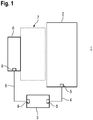
- the controller 3 and the optical sensor 6 are connected via a serial transmission path 8, which is formed by a bus system.
- the controller 3 and the optical sensor 6 each have a serial interface 9.
- the light curtain has eight beam axes.
- the light curtain may also have a different number of beam axes.
- edges of the box 15 can be detected by a predetermined number of interrupted beam axes is detected, wherein the marginal rays, ie the first and last interrupted beam axis have a certain distance.
- the monitoring area 7 is subdivided into three subareas a, b, c, for which different evaluation rules are specified by the controller 3, so that different preprocessing operations are performed for these subareas.
- the protective fields in the subareas a, b and also the warning field can generally be activated via the controller 3 at different times.
Landscapes
- Physics & Mathematics (AREA)
- General Physics & Mathematics (AREA)
- Life Sciences & Earth Sciences (AREA)
- General Life Sciences & Earth Sciences (AREA)
- Geophysics (AREA)
- Arrangements For Transmission Of Measured Signals (AREA)
- Geophysics And Detection Of Objects (AREA)
Priority Applications (1)
| Application Number | Priority Date | Filing Date | Title |
|---|---|---|---|
| EP18161345.6A EP3540380B1 (fr) | 2018-03-13 | 2018-03-13 | Dispositif de surveillance pour une installation |
Applications Claiming Priority (1)
| Application Number | Priority Date | Filing Date | Title |
|---|---|---|---|
| EP18161345.6A EP3540380B1 (fr) | 2018-03-13 | 2018-03-13 | Dispositif de surveillance pour une installation |
Publications (2)
| Publication Number | Publication Date |
|---|---|
| EP3540380A1 true EP3540380A1 (fr) | 2019-09-18 |
| EP3540380B1 EP3540380B1 (fr) | 2021-06-23 |
Family
ID=61628141
Family Applications (1)
| Application Number | Title | Priority Date | Filing Date |
|---|---|---|---|
| EP18161345.6A Active EP3540380B1 (fr) | 2018-03-13 | 2018-03-13 | Dispositif de surveillance pour une installation |
Country Status (1)
| Country | Link |
|---|---|
| EP (1) | EP3540380B1 (fr) |
Cited By (1)
| Publication number | Priority date | Publication date | Assignee | Title |
|---|---|---|---|---|
| DE202022103538U1 (de) | 2022-06-27 | 2023-03-01 | Leuze Electronic Gmbh + Co. Kg | Überwachungsvorrichtung |
Citations (4)
| Publication number | Priority date | Publication date | Assignee | Title |
|---|---|---|---|---|
| WO2008135495A1 (fr) * | 2007-05-03 | 2008-11-13 | Siemens Aktiengesellschaft | Dispositif de mesure doté d'une unité de mesure surveillée et d'une unité de commande pour commander une machine |
| DE102009040384A1 (de) * | 2009-09-07 | 2011-03-10 | Schaeffler Technologies Gmbh & Co. Kg | Sensor und Anordnung zur Zustands- und Prozessüberwachung sowie Verfahren hierfür |
| EP2631682A2 (fr) * | 2012-02-23 | 2013-08-28 | Leuze electronic GmbH + Co KG | Dispositif de détection |
| EP2631681A2 (fr) * | 2012-02-21 | 2013-08-28 | Leuze electronic GmbH + Co KG | Rideau lumineux |
-
2018
- 2018-03-13 EP EP18161345.6A patent/EP3540380B1/fr active Active
Patent Citations (4)
| Publication number | Priority date | Publication date | Assignee | Title |
|---|---|---|---|---|
| WO2008135495A1 (fr) * | 2007-05-03 | 2008-11-13 | Siemens Aktiengesellschaft | Dispositif de mesure doté d'une unité de mesure surveillée et d'une unité de commande pour commander une machine |
| DE102009040384A1 (de) * | 2009-09-07 | 2011-03-10 | Schaeffler Technologies Gmbh & Co. Kg | Sensor und Anordnung zur Zustands- und Prozessüberwachung sowie Verfahren hierfür |
| EP2631681A2 (fr) * | 2012-02-21 | 2013-08-28 | Leuze electronic GmbH + Co KG | Rideau lumineux |
| EP2631682A2 (fr) * | 2012-02-23 | 2013-08-28 | Leuze electronic GmbH + Co KG | Dispositif de détection |
Cited By (1)
| Publication number | Priority date | Publication date | Assignee | Title |
|---|---|---|---|---|
| DE202022103538U1 (de) | 2022-06-27 | 2023-03-01 | Leuze Electronic Gmbh + Co. Kg | Überwachungsvorrichtung |
Also Published As
| Publication number | Publication date |
|---|---|
| EP3540380B1 (fr) | 2021-06-23 |
Similar Documents
| Publication | Publication Date | Title |
|---|---|---|
| EP2053538B1 (fr) | Protection d'une zone de surveillance et support visuel d'un usinage automatisé | |
| EP3220164B1 (fr) | Procédé de fonctionnement d'un capteur écartométrique de surveillance et capteur écartométrique de surveillance | |
| EP1443343B1 (fr) | Détecteur optique avec plusiers sorties de commutation | |
| EP3587894B1 (fr) | Agencement de capteurs et procédé de fonctionnement d'un agencement de capteurs | |
| EP3910230B1 (fr) | Dispositif de surveillance | |
| DE10312972B3 (de) | Optischer Sensor | |
| EP3217195B1 (fr) | Capteur optique | |
| EP3150898B2 (fr) | Procede de commande automatisee d'un composant de machine | |
| EP3415804B1 (fr) | Dispositif de sécurité | |
| EP3540380A1 (fr) | Dispositif de surveillance pour une installation | |
| EP3640522B1 (fr) | Dispositif de surveillance | |
| EP3640521B1 (fr) | Dispositif de surveillance | |
| EP3578867B1 (fr) | Système de détecteurs pourvu de détecteurs de distance optoélectroniques | |
| DE202020103157U1 (de) | Überwachungseinrichtung | |
| EP3249476A1 (fr) | Capteur | |
| EP3955022A1 (fr) | Agencement de capteurs et son procédé de fonctionnement | |
| EP3882505A1 (fr) | Dispositif de surveillance et procédé de fonctionnement d'un dispositif de surveillance | |
| EP3594553A1 (fr) | Dispositif de surveillance d'une zone de danger | |
| EP4119982B1 (fr) | Dispositif de surveillance et procédé de fonctionnement d'un dispositif de surveillance | |
| EP3699634B1 (fr) | Module de capteur | |
| EP3671289B1 (fr) | Système de détection | |
| EP3869240A1 (fr) | Agencement de capteurs et procédé de fonctionnement d'un agencement de capteurs | |
| DE202022103538U1 (de) | Überwachungsvorrichtung | |
| DE102018116264B4 (de) | Lichtgitter | |
| EP4166992A1 (fr) | Capteur optique |
Legal Events
| Date | Code | Title | Description |
|---|---|---|---|
| PUAI | Public reference made under article 153(3) epc to a published international application that has entered the european phase |
Free format text: ORIGINAL CODE: 0009012 |
|
| STAA | Information on the status of an ep patent application or granted ep patent |
Free format text: STATUS: REQUEST FOR EXAMINATION WAS MADE |
|
| 17P | Request for examination filed |
Effective date: 20181010 |
|
| AK | Designated contracting states |
Kind code of ref document: A1 Designated state(s): AL AT BE BG CH CY CZ DE DK EE ES FI FR GB GR HR HU IE IS IT LI LT LU LV MC MK MT NL NO PL PT RO RS SE SI SK SM TR |
|
| AX | Request for extension of the european patent |
Extension state: BA ME |
|
| GRAP | Despatch of communication of intention to grant a patent |
Free format text: ORIGINAL CODE: EPIDOSNIGR1 |
|
| STAA | Information on the status of an ep patent application or granted ep patent |
Free format text: STATUS: GRANT OF PATENT IS INTENDED |
|
| INTG | Intention to grant announced |
Effective date: 20210315 |
|
| GRAS | Grant fee paid |
Free format text: ORIGINAL CODE: EPIDOSNIGR3 |
|
| GRAA | (expected) grant |
Free format text: ORIGINAL CODE: 0009210 |
|
| STAA | Information on the status of an ep patent application or granted ep patent |
Free format text: STATUS: THE PATENT HAS BEEN GRANTED |
|
| AK | Designated contracting states |
Kind code of ref document: B1 Designated state(s): DE |
|
| RBV | Designated contracting states (corrected) |
Designated state(s): DE |
|
| REG | Reference to a national code |
Ref country code: DE Ref legal event code: R096 Ref document number: 502018005782 Country of ref document: DE |
|
| REG | Reference to a national code |
Ref country code: DE Ref legal event code: R097 Ref document number: 502018005782 Country of ref document: DE |
|
| PLBE | No opposition filed within time limit |
Free format text: ORIGINAL CODE: 0009261 |
|
| STAA | Information on the status of an ep patent application or granted ep patent |
Free format text: STATUS: NO OPPOSITION FILED WITHIN TIME LIMIT |
|
| 26N | No opposition filed |
Effective date: 20220324 |
|
| PGFP | Annual fee paid to national office [announced via postgrant information from national office to epo] |
Ref country code: DE Payment date: 20240307 Year of fee payment: 7 |