EP3587894B1 - Agencement de capteurs et procédé de fonctionnement d'un agencement de capteurs - Google Patents
Agencement de capteurs et procédé de fonctionnement d'un agencement de capteurs Download PDFInfo
- Publication number
- EP3587894B1 EP3587894B1 EP18180530.0A EP18180530A EP3587894B1 EP 3587894 B1 EP3587894 B1 EP 3587894B1 EP 18180530 A EP18180530 A EP 18180530A EP 3587894 B1 EP3587894 B1 EP 3587894B1
- Authority
- EP
- European Patent Office
- Prior art keywords
- protective
- fields
- optical sensor
- sensor assembly
- activated
- Prior art date
- Legal status (The legal status is an assumption and is not a legal conclusion. Google has not performed a legal analysis and makes no representation as to the accuracy of the status listed.)
- Active
Links
- 238000000034 method Methods 0.000 title claims description 11
- 230000001681 protective effect Effects 0.000 claims description 155
- 230000003287 optical effect Effects 0.000 claims description 57
- 238000001514 detection method Methods 0.000 claims description 15
- 238000012544 monitoring process Methods 0.000 claims description 14
- 238000011156 evaluation Methods 0.000 claims description 9
- 230000001419 dependent effect Effects 0.000 claims description 4
- 238000013461 design Methods 0.000 description 2
- 238000005259 measurement Methods 0.000 description 2
- 238000005096 rolling process Methods 0.000 description 2
- 208000027418 Wounds and injury Diseases 0.000 description 1
- 230000006978 adaptation Effects 0.000 description 1
- 230000005540 biological transmission Effects 0.000 description 1
- 230000006378 damage Effects 0.000 description 1
- 238000011161 development Methods 0.000 description 1
- 230000018109 developmental process Effects 0.000 description 1
- 230000007613 environmental effect Effects 0.000 description 1
- 208000014674 injury Diseases 0.000 description 1
- 230000005693 optoelectronics Effects 0.000 description 1
- 230000000149 penetrating effect Effects 0.000 description 1
- 238000011144 upstream manufacturing Methods 0.000 description 1
Images


Classifications
-
- F—MECHANICAL ENGINEERING; LIGHTING; HEATING; WEAPONS; BLASTING
- F16—ENGINEERING ELEMENTS AND UNITS; GENERAL MEASURES FOR PRODUCING AND MAINTAINING EFFECTIVE FUNCTIONING OF MACHINES OR INSTALLATIONS; THERMAL INSULATION IN GENERAL
- F16P—SAFETY DEVICES IN GENERAL; SAFETY DEVICES FOR PRESSES
- F16P3/00—Safety devices acting in conjunction with the control or operation of a machine; Control arrangements requiring the simultaneous use of two or more parts of the body
- F16P3/12—Safety devices acting in conjunction with the control or operation of a machine; Control arrangements requiring the simultaneous use of two or more parts of the body with means, e.g. feelers, which in case of the presence of a body part of a person in or near the danger zone influence the control or operation of the machine
- F16P3/14—Safety devices acting in conjunction with the control or operation of a machine; Control arrangements requiring the simultaneous use of two or more parts of the body with means, e.g. feelers, which in case of the presence of a body part of a person in or near the danger zone influence the control or operation of the machine the means being photocells or other devices sensitive without mechanical contact
- F16P3/144—Safety devices acting in conjunction with the control or operation of a machine; Control arrangements requiring the simultaneous use of two or more parts of the body with means, e.g. feelers, which in case of the presence of a body part of a person in or near the danger zone influence the control or operation of the machine the means being photocells or other devices sensitive without mechanical contact using light grids
-
- B—PERFORMING OPERATIONS; TRANSPORTING
- B66—HOISTING; LIFTING; HAULING
- B66F—HOISTING, LIFTING, HAULING OR PUSHING, NOT OTHERWISE PROVIDED FOR, e.g. DEVICES WHICH APPLY A LIFTING OR PUSHING FORCE DIRECTLY TO THE SURFACE OF A LOAD
- B66F9/00—Devices for lifting or lowering bulky or heavy goods for loading or unloading purposes
- B66F9/06—Devices for lifting or lowering bulky or heavy goods for loading or unloading purposes movable, with their loads, on wheels or the like, e.g. fork-lift trucks
- B66F9/063—Automatically guided
-
- B—PERFORMING OPERATIONS; TRANSPORTING
- B66—HOISTING; LIFTING; HAULING
- B66F—HOISTING, LIFTING, HAULING OR PUSHING, NOT OTHERWISE PROVIDED FOR, e.g. DEVICES WHICH APPLY A LIFTING OR PUSHING FORCE DIRECTLY TO THE SURFACE OF A LOAD
- B66F9/00—Devices for lifting or lowering bulky or heavy goods for loading or unloading purposes
- B66F9/06—Devices for lifting or lowering bulky or heavy goods for loading or unloading purposes movable, with their loads, on wheels or the like, e.g. fork-lift trucks
- B66F9/075—Constructional features or details
- B66F9/0755—Position control; Position detectors
-
- G—PHYSICS
- G01—MEASURING; TESTING
- G01S—RADIO DIRECTION-FINDING; RADIO NAVIGATION; DETERMINING DISTANCE OR VELOCITY BY USE OF RADIO WAVES; LOCATING OR PRESENCE-DETECTING BY USE OF THE REFLECTION OR RERADIATION OF RADIO WAVES; ANALOGOUS ARRANGEMENTS USING OTHER WAVES
- G01S17/00—Systems using the reflection or reradiation of electromagnetic waves other than radio waves, e.g. lidar systems
- G01S17/02—Systems using the reflection of electromagnetic waves other than radio waves
- G01S17/04—Systems determining the presence of a target
-
- G—PHYSICS
- G01—MEASURING; TESTING
- G01S—RADIO DIRECTION-FINDING; RADIO NAVIGATION; DETERMINING DISTANCE OR VELOCITY BY USE OF RADIO WAVES; LOCATING OR PRESENCE-DETECTING BY USE OF THE REFLECTION OR RERADIATION OF RADIO WAVES; ANALOGOUS ARRANGEMENTS USING OTHER WAVES
- G01S17/00—Systems using the reflection or reradiation of electromagnetic waves other than radio waves, e.g. lidar systems
- G01S17/02—Systems using the reflection of electromagnetic waves other than radio waves
- G01S17/06—Systems determining position data of a target
- G01S17/08—Systems determining position data of a target for measuring distance only
- G01S17/10—Systems determining position data of a target for measuring distance only using transmission of interrupted, pulse-modulated waves
-
- G—PHYSICS
- G01—MEASURING; TESTING
- G01S—RADIO DIRECTION-FINDING; RADIO NAVIGATION; DETERMINING DISTANCE OR VELOCITY BY USE OF RADIO WAVES; LOCATING OR PRESENCE-DETECTING BY USE OF THE REFLECTION OR RERADIATION OF RADIO WAVES; ANALOGOUS ARRANGEMENTS USING OTHER WAVES
- G01S17/00—Systems using the reflection or reradiation of electromagnetic waves other than radio waves, e.g. lidar systems
- G01S17/02—Systems using the reflection of electromagnetic waves other than radio waves
- G01S17/06—Systems determining position data of a target
- G01S17/42—Simultaneous measurement of distance and other co-ordinates
-
- G—PHYSICS
- G01—MEASURING; TESTING
- G01S—RADIO DIRECTION-FINDING; RADIO NAVIGATION; DETERMINING DISTANCE OR VELOCITY BY USE OF RADIO WAVES; LOCATING OR PRESENCE-DETECTING BY USE OF THE REFLECTION OR RERADIATION OF RADIO WAVES; ANALOGOUS ARRANGEMENTS USING OTHER WAVES
- G01S17/00—Systems using the reflection or reradiation of electromagnetic waves other than radio waves, e.g. lidar systems
- G01S17/88—Lidar systems specially adapted for specific applications
- G01S17/93—Lidar systems specially adapted for specific applications for anti-collision purposes
- G01S17/931—Lidar systems specially adapted for specific applications for anti-collision purposes of land vehicles
-
- G—PHYSICS
- G01—MEASURING; TESTING
- G01S—RADIO DIRECTION-FINDING; RADIO NAVIGATION; DETERMINING DISTANCE OR VELOCITY BY USE OF RADIO WAVES; LOCATING OR PRESENCE-DETECTING BY USE OF THE REFLECTION OR RERADIATION OF RADIO WAVES; ANALOGOUS ARRANGEMENTS USING OTHER WAVES
- G01S7/00—Details of systems according to groups G01S13/00, G01S15/00, G01S17/00
- G01S7/48—Details of systems according to groups G01S13/00, G01S15/00, G01S17/00 of systems according to group G01S17/00
- G01S7/481—Constructional features, e.g. arrangements of optical elements
- G01S7/4811—Constructional features, e.g. arrangements of optical elements common to transmitter and receiver
- G01S7/4812—Constructional features, e.g. arrangements of optical elements common to transmitter and receiver transmitted and received beams following a coaxial path
-
- G—PHYSICS
- G01—MEASURING; TESTING
- G01V—GEOPHYSICS; GRAVITATIONAL MEASUREMENTS; DETECTING MASSES OR OBJECTS; TAGS
- G01V8/00—Prospecting or detecting by optical means
- G01V8/10—Detecting, e.g. by using light barriers
- G01V8/12—Detecting, e.g. by using light barriers using one transmitter and one receiver
Definitions
- the invention relates to a sensor arrangement according to the preamble of claim 1 and a method for operating such a sensor arrangement.
- Such sensor arrangements are used to protect dangerous areas on vehicles.
- the sensor arrangement advantageously meets the safety requirements for use in the field of safety technology.
- the vehicles secured with the sensor arrangement can in particular be in the form of driverless transport systems which are generally used to transport goods.
- a danger zone is secured with the sensor arrangement, in particular in advance, by using the sensor arrangement to monitor a protective field that at least partially covers this danger zone.
- the sensor arrangement advantageously has an optical sensor which can be designed in the form of a surface distance sensor, ie a scanning distance sensor.
- the optical sensor Depending on object detections in the protective field, the optical sensor generates a binary switching signal, the first switching state of which is a safety signal and the second switching state of which is a release signal. If no object is detected in the protective field with the optical sensor, it generates a release signal so that the vehicle can continue to move unhindered. However, if an object intervention in the protective field is generated with the optical sensor, the optical sensor generates a safety signal, which is in particular a stop signal or a braking signal for the vehicle.
- a safety function is thus implemented in such a way that if, for example, a person enters the danger area monitored by the protective field, the vehicle stops immediately or at least brakes, thereby excluding any danger to the person.
- the roadway of the vehicle is usually delimited by roadway boundaries, for example by machines or systems.
- roadway boundaries for example by machines or systems.
- the optical sensor evaluates this as an object intrusion, which generates the safety signal.
- the resulting stopping or braking of the vehicle is unnecessary, since this lane delimitation does not represent a dangerous intervention.
- This method reaches its limits in particular when the roadway consists of a narrow aisle that is bordered on both sides by roadway boundaries and is only slightly wider than the vehicle itself.
- a protective field adapted to the dimensions, in particular the width of the aisle is provided to monitor the danger zone.
- the U.S. 2011/0153139 A1 relates to an optoelectronic sensor, in particular a laser scanner, for a vehicle that is moving on a lane that is delimited on both sides.
- the sensor has a light receiver for converting received light into electrical signals and an evaluation unit which is designed to determine the position of objects in a monitoring area of the sensor from the electrical signals and to detect whether an impermissible object is within a location and/or expansion of a dynamically changing protective field, with a safe output being provided via which the evaluation unit can output a stopping or braking signal to the vehicle when an intrusion into the protective field is detected.
- the evaluation unit is also designed to determine boundaries of the roadway from the electrical signals to recognize and dynamically fit the protective field into the boundaries.
- the protective field has a longitudinal extent that is dependent on the speed of the vehicle, approximately in the direction of travel, and a predefined transverse extent that is adapted to the vehicle and/or the roadway. From the EP 3 312 131 A a generic sensor is also known.
- the invention is based on the object of providing a sensor arrangement and a method by means of which reliable monitoring of a danger zone of a vehicle is ensured with high availability of the vehicle.
- the invention relates to a sensor arrangement with an optical sensor for monitoring a danger area on a vehicle, which is moving along a roadway delimited on both sides by a roadway boundary.
- the optical sensor is designed to detect objects in at least one protective field and, depending on this, to generate a binary switching signal whose switching states are on the one hand a safety signal and on the other hand a release signal for the vehicle.
- Several protective fields activated at the same time are provided. An object is detected in each activated protective field by means of the optical sensor.
- a selection logic is provided in an evaluation unit of the optical sensor, in which at least one activated protective field is selected. Only depending on an object detection in the safety signal is generated in the at least one selected protective field.
- the invention further relates to a corresponding method.
- the safety function is implemented in such a way that an intrusion of the person or the object into the danger area is reliably detected, as a result of which the optical sensor generates a safety signal that is designed in particular as a stop signal or brake signal.
- the optical sensor used for this purpose is preferably designed as a safety sensor, ie it has a fail-safe design that meets the requirements of the relevant safety standards.
- An essential advantage of the invention is that detections of the lane boundary by the optical sensor do not result in the generation of a safety signal and thus in the vehicle not being stopped or braked unnecessarily, so that the availability of the vehicle is not unnecessarily restricted.
- This advantage is also achieved in particular when the roadway is a narrow aisle bounded on both sides, which is bounded on both sides by roadway boundaries and whose width is only slightly greater than the width of the vehicle.
- the method according to the invention appears to be more complicated than the known monitoring of the danger area with only one protective field, the contour of which is continuously adapted to the roadway boundary.
- an adaptation of the protective field is extremely complex and problematic, particularly in the case of rapidly changing environmental conditions. This applies in particular when the vehicle is being moved along a lane formed by a narrow passage between two lane boundaries. The unavoidable rolling movements of the vehicle then lead to the edge areas of the lane boundary protruding into the protective field.
- the protective fields are then selected and extracted that are relevant for the danger zone monitoring.
- appropriate logic operations in particular object detections in selected protective fields, the influence of the roadway boundaries can then be safely eliminated when detecting objects.
- object detection can only be carried out in the danger area and thus without the disturbing influences of the roadway boundaries.
- one or more activated protective fields are adapted to the roadway.
- the optical sensor can be used to obtain measured values from the lane boundaries, with the activated protective fields depending on the measured values.
- the activated protective fields can depend on the load status and/or the speed of the vehicle.
- the activated protective fields can be specified by an external unit, for example the vehicle controller.
- the activated protective fields do not have to be adapted exactly and in particular not continuously to the current driving situation of the vehicle.
- the individually activated protective fields only have to be roughly adapted to the lane boundary and thus to the danger area on the vehicle.
- Various geometries and arrangements of activated protective fields are possible.
- Activated protective fields can also partially overlap.
- one or more activated protective fields are designed as partial protective fields that only extend over a partial angular range of the roadway.
- the optical sensor generates a release signal if there is no object intervention in at least one selected protective field.
- the activated protective fields are adapted to the possible vehicle movements in such a way that at least one activated protective field is present for every possible state of movement, into which no road boundary protrudes, so that only the danger area is covered with this.
- the straight-line transport movement of the vehicle can at most be superimposed by a rolling movement, ie a pendulum movement with respect to its longitudinal axis.
- the only requirement for generating the release signal is that no object is detected in the at least one selected protective field. With this selection, all protective fields in which object intrusions originating from the roadway boundaries are possibly registered are discarded. Conversely, if object intrusions are registered in all activated protective fields, the safety signal is generated, which represents a safe and reliable response to an intrusion of an object or person into the danger zone. This is based on the fact that the protective fields are selected in such a way that, for each vehicle position, a protective field only covers the danger area. In this way, measured values originating from the lane boundary can be reliably eliminated without having to continuously adapt the contour of protective fields to the recess of the lane boundary, which enables danger area monitoring without the disruptive influences of the lane boundary.
- a number of activated protective fields are linked to form a number of logic protective fields in that object detections in these activated protective fields are linked to one another, with the logical links being used to determine whether or not there is an object intervention in one or more logic protective fields .
- the optical sensor If there is no object intervention for the or at least one logic protective field, the optical sensor generates a release signal.
- At least one logic protective field of several logic protective fields is again dimensioned in such a way that only the danger area but not the lane boundary is detected in this field, regardless of the current vehicle position.
- the selection logic is then again such that the release signal is only generated by the optical sensor if no object is detected in at least one logic protective field.
- the safety signal is only generated if an object intervention is registered in all logic protective fields.
- the optical sensor is a surface distance sensor.
- a surface distance sensor of this type has a distance sensor which emits light beams which periodically sweep over a surface monitoring area. With such a surface distance sensor, the position of an object can be determined in a protective field.
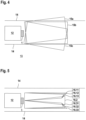
- FIG 1 shows a first exemplary embodiment of an optical sensor 1 according to the invention in the form of a surface distance sensor.
- the components of the optical sensor 1 are integrated in a fixed housing 2 .
- the optical sensor 1 has a transmitter 4 emitting transmitted light beams 3 and a receiver 6 receiving received light beams 5, which form a distance sensor.
- the distance measurements are advantageously carried out using a pulse transit time method.
- the transmitter 4, the receiver 6 and a receiving optics 7 arranged upstream of them are assigned to a deflection unit 8 rotating about an axis of rotation D.
- the transmitted light beams 3 are periodically deflected within a scanning area in order to detect objects 9 present there.
- the positions of the object 9 are determined by the distance measurements and by detecting the deflection position of the deflection unit 8 .
- FIG figure 2 1 shows a variant of the optical sensor 1 according to FIG figure 1 .
- the transmitter 4 and receiver 6 are mounted in a measuring head 10 which rotates about an axis of rotation D and is seated on a stationary base 11 .
- the optical sensor 1 according to figure 1 respectively figure 2 has an evaluation unit for evaluating the received signals generated in the receiver 6 .
- the optical sensor 1 is designed as a safety sensor and therefore has a fail-safe design.
- the evaluation unit has a redundant structure, in particular in the form of two computer units that monitor each other cyclically.
- FIG. 1 shows a vehicle 12, such as a VNA truck, moving along a straight path in an aisle as illustrated by the arrow 13 moves, which is bounded on both sides by a lane boundary 14.
- the aisle 13 is formed as a narrow aisle in a warehouse or the like, the width of the aisle 13 being only slightly larger than the vehicle width.
- the lane boundaries 14 are formed by storage areas for goods, in particular by shelves.
- the optical sensor 1 At the front of the vehicle 12 is the optical sensor 1 according to FIG figure 1 respectively figure 2 assembled.
- the signals generated by the optical sensor 1 are fed to a controller (not shown).
- the area in front of the vehicle 12, ie the area of the aisle 13 in front of the vehicle 12 is monitored as a danger area.
- the optical sensor 1 leads as shown in FIG Figures 4 and 5 illustrated, a protective field monitoring.
- the optical sensor 1 generates a binary switching signal as the output signal, which has two switching states.
- a first switching state is a safety signal, which is embodied as a stop signal or braking signal for vehicle 12 .
- a second switching state is an enable signal. If the controller of the vehicle 12 receives the release signal, the vehicle 12 continues driving without restrictions.
- a safety signal should only be generated if a person or an object enters the danger area or the area of the aisle 13 in front of the vehicle 12 . However, detections of the lane boundary 14 with the optical sensor 1 should not lead to the generation of the safety signal. This is achieved with the protective field monitoring according to the invention in the Figures 4 and 5 is illustrated.
- the optical sensor 1 simultaneously detects an object in three activated protective fields 15a, 15b, 15c.
- three protective fields 15a, 15b, 15c are provided, although a different number of protective fields is of course also possible.
- the protective fields 15a, 15b, 15c all have the same rectangular shape and are arranged in a fan shape, partially overlapping.
- the activated protective fields 15a, 15b, 15c are adapted to the geometry of the aisle 13 and the roadway boundary 14, in particular by determining the contours of the roadway boundary 14.
- the activated protective fields 15a, 15b, 15c can also be specified as a function of the load status or the speed.
- the activated protective fields 15a, 15b, 15c can be specified by external control signals, which can be generated in the controller of the vehicle 12, for example.
- the vehicle 12 is moving in aisle 13 along a straight path.
- snaking movements ie pendulum movements of the vehicle 12 with respect to its longitudinal axis
- the fan-shaped protective fields 15a, 15b, 15c are selected in such a way that, regardless of whether the vehicle 12 is swinging towards the right or left lane boundary 14, at least one activated protective field always encompasses the danger area, i.e. aisle 13, but not lane boundary 14.
- a selection logic is integrated in the evaluation unit of the optical sensor 1, in which, depending on the object detections in the protective fields 15a, 15b, 15c, at least one activated protective field 15a, 15b, 15c is selected, in order then only depending on this selected protective field 15a, 15b, 15c to generate the switching signal.
- the selection logic is designed such that if no object is detected in at least one protective field 15a, 15b, 15c, the enable signal is generated as a switching signal, since this ensures that there is no object in the danger zone. This is based on the fact that protective fields 15a, 15b, 15c, which may intrude on objects due to the lane delimitation 14 have, are not taken into account by the selection logic from the outset. Conversely, the selection logic is designed such that if object intrusions are registered for all activated protective fields 15a, 15b, 15c, the safety signal is output as a switching signal, since in this case an object must be present in the danger area.
- the partial protective fields 16.11, 16.12, 16.13, 16.2, 16.31, 16.32, 16.33 only extend over partial angular areas of the aisle 13.
- the central partial protective field 16.2 extends over a partial angular area of about 30°.
- the partial protective fields 16.11, 16.12, 16.13 are located on the left edge of the vehicle 12 (seen in its direction of travel).
- the partial protective fields 16.31, 16.32, 16.33 are located on the right edge of the vehicle 12.
- the selection logic of the optical sensor 1 works in such a way that several logic protective fields L 1 , L 2 , L 3 are formed by logical combinations of partial protective fields 16.11, 16.12, 16.13, 16.2, 16.31, 16.32, 16.33.
- a first logic protective field L 1 is formed by linking the partial protective fields 16.11, 16.2 and 16.31.
- a violation of the logic protective field L 1 ie an object intrusion in the logic protective field L 1 is present if there is an object intrusion either in the partial protective field 16.11 or in the partial protective field 16.2 or in the partial protective field 16.31.
- a second logic protective field L 2 is formed by linking the partial protective fields 16.12, 16.2 and 16.32.
- the logic protective field L 2 is violated if there is an object intervention either in the partial protective field 16.12 or in the partial protective field 16.2 or in the partial protective field 16.32.
- a third logic protective field L 3 is formed by linking the partial protective fields 16.13, 16.2 and 16.33.
- a violation of the logic protective field L 3 is present if there is an object intervention either in the partial protective field 16.13 or in the partial protective field 16.2 or in the partial protective field 16.33.
- optical sensor 1 An object penetrating into the danger area is only considered to be recognized if an injury is registered for all three logic protective fields L 1 , L 2 , L 3 . Then the optical sensor 1 outputs the safety signal as a switching signal. In all other cases, the optical sensor 1 outputs the release signal as a switching signal.
Landscapes
- Engineering & Computer Science (AREA)
- Physics & Mathematics (AREA)
- Electromagnetism (AREA)
- General Physics & Mathematics (AREA)
- Computer Networks & Wireless Communication (AREA)
- Radar, Positioning & Navigation (AREA)
- Remote Sensing (AREA)
- Transportation (AREA)
- Structural Engineering (AREA)
- Mechanical Engineering (AREA)
- Life Sciences & Earth Sciences (AREA)
- General Engineering & Computer Science (AREA)
- Civil Engineering (AREA)
- Geology (AREA)
- General Life Sciences & Earth Sciences (AREA)
- Geophysics (AREA)
- Traffic Control Systems (AREA)
Claims (15)
- Agencement de capteurs comportant un capteur optique (1) pour la surveillance d'une zone dangereuse sur un véhicule (12) se déplaçant sur une chaussée délimitée des deux côtés par une limite de chaussée (14), le capteur optique (1) étant conçu pour détecter des objets dans au moins un champ de protection (15a, 15b, 15c) et pour générer en conséquence un signal de commutation binaire dont les états de commutation sont d'une part un signal de sécurité et d'autre part un signal de libération du véhicule (12), caractérisé en ce que plusieurs champs de protection activés simultanément (15a, 15b, 15c) sont prévus, la détection d'objets ayant lieu dans chaque champ de protection activé (15a, 15b, 15c) au moyen du capteur optique (1), et en ce qu'une logique de sélection est prévue dans une unité d'évaluation du capteur optique (1), logique de sélection dans laquelle au moins un champ de protection activé (15a, 15b, 15c) est sélectionné, dans laquelle tous les champs de protection activés sont contrôlés simultanément quant à une éventuelle interférence d'objets, mais le signal de sécurité n'est généré qu'en fonction de la détection d'objets dans au moins un champ de protection sélectionné (15a, 15b, 15c).
- Agencement de capteurs selon la revendication 1, caractérisé par le fait que les champs de protection activés (15a, 15b, 15c) ne sont pas conçus en permanence à la situation routière courante.
- Agencement de capteurs selon la revendication 2, caractérisé par le fait que les valeurs mesurées des limites de la chaussée (14) sont obtenues à l'aide du capteur optique (1), les champs de protection activés (15a, 15b, 15c) dépendant des valeurs mesurées.
- Agencement de capteurs selon l'une des revendications 1 à 3, caractérisé par le fait que les champs de protection activés (15a, 15b, 15c) dépendent de l'état de charge et/ou de la vitesse du véhicule (12).
- Agencement de capteurs selon l'une des revendications 1 à 4, caractérisé par le fait qu'un ou plusieurs champs de protection activés (15a, 15b, 15c) sont formés en tant que champs de protection partiels (16.11, 16.12, 16.13, 16.2, 16.31, 16.32, 16.33) qui ne s'étendent que sur une plage angulaire partielle de la chaussée.
- Agencement de capteurs selon l'une des revendications 1 à 5, caractérisé par le fait que les champs de protection activés (15a, 15b, 15c) se chevauchent partiellement.
- Agencement de capteurs selon l'une des revendications 1 à 6, caractérisé par le fait que le capteur optique (1) génère un signal de libération si aucun objet n'est engagé dans au moins un champ de protection sélectionné (15a, 15b, 15c).
- Agencement de capteurs selon l'une des revendications 1 à 7, caractérisé en ce que plusieurs champs de protection activés (15a, 15b, 15c) sont reliés pour former plusieurs champs de protection logiques en reliant les détections d'objets dans ces champs de protection activés (15a, 15b, 15c) les uns aux autres.
- Agencement de capteurs selon la revendication 8, caractérisé en ce que les opérations logiques sont utilisées pour déterminer si une intervention d'objet est présente ou non dans un ou plusieurs champs de protection logique.
- Agencement de capteurs selon l'une des revendications 8 ou 9, caractérisé en ce que les champs de protection activés (15a, 15b, 15c) sont conçus comme des champs de protection partiels (16.11, 16.12, 16.13, 16.2, 16.31, 16.32, 16.33).
- Agencement de capteurs selon l'une des revendications 9 ou 10, caractérisé par le fait que le capteur optique (1) ne génère un signal de validation que s'il n'y a pas d'interférence d'objet pour le champ de protection logique ou au moins un champ de protection logique.
- Agencement de capteurs selon l'une des revendications 1 à 11, caractérisé par le fait que le signal de sécurité est un signal d'arrêt ou un signal de freinage pour le véhicule (12).
- Agencement de capteurs selon l'une des revendications 1 à 12, caractérisé par le fait que le capteur optique (1) est un capteur de sécurité.
- Agencement de capteurs selon l'une des revendications 1 à 13, caractérisé par le fait que le capteur optique (1) est un capteur de distance.
- Procédé de fonctionnement d'un ensemble de capteurs avec un capteur optique (1) pour la surveillance d'une zone dangereuse sur un véhicule (12) qui se déplace le long d'une route délimitée des deux côtés par une limite de route (14), dans lequel les objets dans au moins un champ de protection (15a, 15b, 15c) sont détectés par le capteur optique, 15c) sont détectés par le capteur optique (1) et un signal de commutation binaire est généré en fonction de celui-ci, dont les états de commutation sont d'une part un signal de sécurité et d'autre part un signal de libération du véhicule (12), caractérisé par le fait qu'une pluralité de champs de protection activés simultanément (15a, 15b, 15c) sont prévus, la détection d'objet ayant lieu dans chaque champ de protection activé (15a, 15b, 15c) au moyen du capteur optique (1), et en ce qu'une logique de sélection est prévue dans une unité d'évaluation du capteur optique (1), dans laquelle au moins un champ de protection activé (15a, 15b, 15c) est sélectionné, dans lequel tous les champs de protection activés sont contrôlés simultanément pour d'éventuelles interventions d'objets, mais le signal de sécurité n'est généré qu'en fonction d'une détection d'objet dans au moins un champ de protection sélectionné (15a, 15b, 15c).
Priority Applications (1)
| Application Number | Priority Date | Filing Date | Title |
|---|---|---|---|
| EP18180530.0A EP3587894B1 (fr) | 2018-06-28 | 2018-06-28 | Agencement de capteurs et procédé de fonctionnement d'un agencement de capteurs |
Applications Claiming Priority (1)
| Application Number | Priority Date | Filing Date | Title |
|---|---|---|---|
| EP18180530.0A EP3587894B1 (fr) | 2018-06-28 | 2018-06-28 | Agencement de capteurs et procédé de fonctionnement d'un agencement de capteurs |
Publications (2)
| Publication Number | Publication Date |
|---|---|
| EP3587894A1 EP3587894A1 (fr) | 2020-01-01 |
| EP3587894B1 true EP3587894B1 (fr) | 2023-08-09 |
Family
ID=62841853
Family Applications (1)
| Application Number | Title | Priority Date | Filing Date |
|---|---|---|---|
| EP18180530.0A Active EP3587894B1 (fr) | 2018-06-28 | 2018-06-28 | Agencement de capteurs et procédé de fonctionnement d'un agencement de capteurs |
Country Status (1)
| Country | Link |
|---|---|
| EP (1) | EP3587894B1 (fr) |
Families Citing this family (3)
| Publication number | Priority date | Publication date | Assignee | Title |
|---|---|---|---|---|
| DE202020103157U1 (de) * | 2020-06-02 | 2021-02-09 | Leuze Electronic Gmbh + Co. Kg | Überwachungseinrichtung |
| EP3945238B8 (fr) * | 2020-07-30 | 2023-01-25 | Leuze electronic GmbH + Co. KG | Dispositif de surveillance et procédé de fonctionnement d'un dispositif de surveillance |
| DE102020122204A1 (de) | 2020-08-25 | 2022-03-03 | Jungheinrich Aktiengesellschaft | System mit einem Regalshuttlefahrzeug und einem Lagerregal |
Family Cites Families (3)
| Publication number | Priority date | Publication date | Assignee | Title |
|---|---|---|---|---|
| US6121872A (en) * | 1989-04-15 | 2000-09-19 | Bayerische Motoren Werke Ag | Object sensing device for motor vehicles |
| EP2339376B1 (fr) * | 2009-12-17 | 2012-02-08 | Sick Ag | Capteur optoélectronique |
| DE102016120117A1 (de) * | 2016-10-21 | 2018-04-26 | Linde Material Handling Gmbh | Flurförderzeug mit einer Sensoreinrichtung zur Überwachung eines Umgebungsbereiches |
-
2018
- 2018-06-28 EP EP18180530.0A patent/EP3587894B1/fr active Active
Also Published As
| Publication number | Publication date |
|---|---|
| EP3587894A1 (fr) | 2020-01-01 |
Similar Documents
| Publication | Publication Date | Title |
|---|---|---|
| EP2339376B1 (fr) | Capteur optoélectronique | |
| EP1046925B1 (fr) | Dispositif optoélectronique | |
| EP3339715B1 (fr) | Système de protection d'accès | |
| EP1494048B1 (fr) | Rideau de lumière | |
| EP3587894B1 (fr) | Agencement de capteurs et procédé de fonctionnement d'un agencement de capteurs | |
| EP2428862B1 (fr) | Dispositif et procédé destinés à la commande de sécurité d'un véhicule | |
| EP3330740B1 (fr) | Procédé de détection d'objets dans une zone de détection | |
| EP3455153B1 (fr) | Procédé et système pour éviter des collisions par des grues | |
| EP2306063B1 (fr) | Capteur de sécurité | |
| EP1788467A2 (fr) | Dispositif de protection | |
| EP2302416A1 (fr) | Scanner de sécurité | |
| EP3401702B1 (fr) | Système de capteur | |
| WO2020104454A1 (fr) | Procédé de surveillance fiable du fonctionnement d'un dispositif de transport électromagnétique | |
| EP3415804B1 (fr) | Dispositif de sécurité | |
| WO2003019233A1 (fr) | Dispositif de detection d'obstacles | |
| EP3287809B1 (fr) | Procédé de fonctionnement d'un dispositif de baleyage et dispositif de baleyage | |
| EP3640522B1 (fr) | Dispositif de surveillance | |
| EP3882505B1 (fr) | Dispositif de surveillance et procédé de fonctionnement d'un dispositif de surveillance | |
| EP3249476B1 (fr) | Capteur | |
| EP3919801A1 (fr) | Dispositif de surveillance | |
| EP3671289B1 (fr) | Système de détection | |
| EP4119982B1 (fr) | Dispositif de surveillance et procédé de fonctionnement d'un dispositif de surveillance | |
| EP3705368A1 (fr) | Dispositif de surveillance | |
| DE19739110A1 (de) | Verkehrs-Warndetektor | |
| EP3872526B1 (fr) | Dispositif de surveillance d'une zone protégée |
Legal Events
| Date | Code | Title | Description |
|---|---|---|---|
| PUAI | Public reference made under article 153(3) epc to a published international application that has entered the european phase |
Free format text: ORIGINAL CODE: 0009012 |
|
| STAA | Information on the status of an ep patent application or granted ep patent |
Free format text: STATUS: REQUEST FOR EXAMINATION WAS MADE |
|
| 17P | Request for examination filed |
Effective date: 20190222 |
|
| AK | Designated contracting states |
Kind code of ref document: A1 Designated state(s): AL AT BE BG CH CY CZ DE DK EE ES FI FR GB GR HR HU IE IS IT LI LT LU LV MC MK MT NL NO PL PT RO RS SE SI SK SM TR |
|
| AX | Request for extension of the european patent |
Extension state: BA ME |
|
| STAA | Information on the status of an ep patent application or granted ep patent |
Free format text: STATUS: EXAMINATION IS IN PROGRESS |
|
| 17Q | First examination report despatched |
Effective date: 20210817 |
|
| STAA | Information on the status of an ep patent application or granted ep patent |
Free format text: STATUS: EXAMINATION IS IN PROGRESS |
|
| GRAP | Despatch of communication of intention to grant a patent |
Free format text: ORIGINAL CODE: EPIDOSNIGR1 |
|
| STAA | Information on the status of an ep patent application or granted ep patent |
Free format text: STATUS: GRANT OF PATENT IS INTENDED |
|
| INTG | Intention to grant announced |
Effective date: 20230224 |
|
| GRAS | Grant fee paid |
Free format text: ORIGINAL CODE: EPIDOSNIGR3 |
|
| RBV | Designated contracting states (corrected) |
Designated state(s): DE |
|
| GRAA | (expected) grant |
Free format text: ORIGINAL CODE: 0009210 |
|
| STAA | Information on the status of an ep patent application or granted ep patent |
Free format text: STATUS: THE PATENT HAS BEEN GRANTED |
|
| P01 | Opt-out of the competence of the unified patent court (upc) registered |
Effective date: 20230623 |
|
| AK | Designated contracting states |
Kind code of ref document: B1 Designated state(s): DE |
|
| REG | Reference to a national code |
Ref country code: DE Ref legal event code: R096 Ref document number: 502018012911 Country of ref document: DE |
|
| PLBI | Opposition filed |
Free format text: ORIGINAL CODE: 0009260 |