EP3540356B1 - Radiant body - Google Patents
Radiant body Download PDFInfo
- Publication number
- EP3540356B1 EP3540356B1 EP19162139.0A EP19162139A EP3540356B1 EP 3540356 B1 EP3540356 B1 EP 3540356B1 EP 19162139 A EP19162139 A EP 19162139A EP 3540356 B1 EP3540356 B1 EP 3540356B1
- Authority
- EP
- European Patent Office
- Prior art keywords
- tubular conduit
- main tubular
- bushing
- radiant body
- opening
- Prior art date
- Legal status (The legal status is an assumption and is not a legal conclusion. Google has not performed a legal analysis and makes no representation as to the accuracy of the status listed.)
- Active
Links
Images


Classifications
-
- F—MECHANICAL ENGINEERING; LIGHTING; HEATING; WEAPONS; BLASTING
- F28—HEAT EXCHANGE IN GENERAL
- F28F—DETAILS OF HEAT-EXCHANGE AND HEAT-TRANSFER APPARATUS, OF GENERAL APPLICATION
- F28F9/00—Casings; Header boxes; Auxiliary supports for elements; Auxiliary members within casings
- F28F9/02—Header boxes; End plates
- F28F9/0246—Arrangements for connecting header boxes with flow lines
- F28F9/0248—Arrangements for sealing connectors to header boxes
-
- B—PERFORMING OPERATIONS; TRANSPORTING
- B21—MECHANICAL METAL-WORKING WITHOUT ESSENTIALLY REMOVING MATERIAL; PUNCHING METAL
- B21C—MANUFACTURE OF METAL SHEETS, WIRE, RODS, TUBES, PROFILES OR LIKE SEMI-MANUFACTURED PRODUCTS OTHERWISE THAN BY ROLLING; AUXILIARY OPERATIONS USED IN CONNECTION WITH METAL-WORKING WITHOUT ESSENTIALLY REMOVING MATERIAL
- B21C37/00—Manufacture of metal sheets, rods, wire, tubes, profiles or like semi-manufactured products, not otherwise provided for; Manufacture of tubes of special shape
- B21C37/06—Manufacture of metal sheets, rods, wire, tubes, profiles or like semi-manufactured products, not otherwise provided for; Manufacture of tubes of special shape of tubes or metal hoses; Combined procedures for making tubes, e.g. for making multi-wall tubes
- B21C37/15—Making tubes of special shape; Making tube fittings
- B21C37/28—Making tube fittings for connecting pipes, e.g. U-pieces
- B21C37/29—Making branched pieces, e.g. T-pieces
- B21C37/296—Making branched pieces starting from strip material; Making branched tubes by securing a secondary tube in an opening in the undeformed wall of a principal tube
-
- F—MECHANICAL ENGINEERING; LIGHTING; HEATING; WEAPONS; BLASTING
- F16—ENGINEERING ELEMENTS AND UNITS; GENERAL MEASURES FOR PRODUCING AND MAINTAINING EFFECTIVE FUNCTIONING OF MACHINES OR INSTALLATIONS; THERMAL INSULATION IN GENERAL
- F16L—PIPES; JOINTS OR FITTINGS FOR PIPES; SUPPORTS FOR PIPES, CABLES OR PROTECTIVE TUBING; MEANS FOR THERMAL INSULATION IN GENERAL
- F16L15/00—Screw-threaded joints; Forms of screw-threads for such joints
- F16L15/006—Screw-threaded joints; Forms of screw-threads for such joints with straight threads
- F16L15/008—Screw-threaded joints; Forms of screw-threads for such joints with straight threads with sealing rings
-
- F—MECHANICAL ENGINEERING; LIGHTING; HEATING; WEAPONS; BLASTING
- F16—ENGINEERING ELEMENTS AND UNITS; GENERAL MEASURES FOR PRODUCING AND MAINTAINING EFFECTIVE FUNCTIONING OF MACHINES OR INSTALLATIONS; THERMAL INSULATION IN GENERAL
- F16L—PIPES; JOINTS OR FITTINGS FOR PIPES; SUPPORTS FOR PIPES, CABLES OR PROTECTIVE TUBING; MEANS FOR THERMAL INSULATION IN GENERAL
- F16L41/00—Branching pipes; Joining pipes to walls
- F16L41/08—Joining pipes to walls or pipes, the joined pipe axis being perpendicular to the plane of a wall or to the axis of another pipe
- F16L41/082—Non-disconnectable joints, e.g. soldered, adhesive or caulked joints
-
- F—MECHANICAL ENGINEERING; LIGHTING; HEATING; WEAPONS; BLASTING
- F28—HEAT EXCHANGE IN GENERAL
- F28D—HEAT-EXCHANGE APPARATUS, NOT PROVIDED FOR IN ANOTHER SUBCLASS, IN WHICH THE HEAT-EXCHANGE MEDIA DO NOT COME INTO DIRECT CONTACT
- F28D1/00—Heat-exchange apparatus having stationary conduit assemblies for one heat-exchange medium only, the media being in contact with different sides of the conduit wall, in which the other heat-exchange medium is a large body of fluid, e.g. domestic or motor car radiators
- F28D1/02—Heat-exchange apparatus having stationary conduit assemblies for one heat-exchange medium only, the media being in contact with different sides of the conduit wall, in which the other heat-exchange medium is a large body of fluid, e.g. domestic or motor car radiators with heat-exchange conduits immersed in the body of fluid
- F28D1/04—Heat-exchange apparatus having stationary conduit assemblies for one heat-exchange medium only, the media being in contact with different sides of the conduit wall, in which the other heat-exchange medium is a large body of fluid, e.g. domestic or motor car radiators with heat-exchange conduits immersed in the body of fluid with tubular conduits
- F28D1/053—Heat-exchange apparatus having stationary conduit assemblies for one heat-exchange medium only, the media being in contact with different sides of the conduit wall, in which the other heat-exchange medium is a large body of fluid, e.g. domestic or motor car radiators with heat-exchange conduits immersed in the body of fluid with tubular conduits the conduits being straight
-
- F—MECHANICAL ENGINEERING; LIGHTING; HEATING; WEAPONS; BLASTING
- F28—HEAT EXCHANGE IN GENERAL
- F28F—DETAILS OF HEAT-EXCHANGE AND HEAT-TRANSFER APPARATUS, OF GENERAL APPLICATION
- F28F9/00—Casings; Header boxes; Auxiliary supports for elements; Auxiliary members within casings
- F28F9/02—Header boxes; End plates
- F28F9/04—Arrangements for sealing elements into header boxes or end plates
- F28F9/16—Arrangements for sealing elements into header boxes or end plates by permanent joints, e.g. by rolling
- F28F9/18—Arrangements for sealing elements into header boxes or end plates by permanent joints, e.g. by rolling by welding
- F28F9/182—Arrangements for sealing elements into header boxes or end plates by permanent joints, e.g. by rolling by welding the heat-exchange conduits having ends with a particular shape, e.g. deformed; the heat-exchange conduits or end plates having supplementary joining means, e.g. abutments
-
- F—MECHANICAL ENGINEERING; LIGHTING; HEATING; WEAPONS; BLASTING
- F28—HEAT EXCHANGE IN GENERAL
- F28F—DETAILS OF HEAT-EXCHANGE AND HEAT-TRANSFER APPARATUS, OF GENERAL APPLICATION
- F28F9/00—Casings; Header boxes; Auxiliary supports for elements; Auxiliary members within casings
- F28F9/26—Arrangements for connecting different sections of heat-exchange elements, e.g. of radiators
- F28F9/262—Arrangements for connecting different sections of heat-exchange elements, e.g. of radiators for radiators
- F28F9/268—Arrangements for connecting different sections of heat-exchange elements, e.g. of radiators for radiators by permanent joints, e.g. by welding
-
- F—MECHANICAL ENGINEERING; LIGHTING; HEATING; WEAPONS; BLASTING
- F24—HEATING; RANGES; VENTILATING
- F24D—DOMESTIC- OR SPACE-HEATING SYSTEMS, e.g. CENTRAL HEATING SYSTEMS; DOMESTIC HOT-WATER SUPPLY SYSTEMS; ELEMENTS OR COMPONENTS THEREFOR
- F24D19/00—Details
- F24D19/0002—Means for connecting central heating radiators to circulation pipes
-
- F—MECHANICAL ENGINEERING; LIGHTING; HEATING; WEAPONS; BLASTING
- F28—HEAT EXCHANGE IN GENERAL
- F28D—HEAT-EXCHANGE APPARATUS, NOT PROVIDED FOR IN ANOTHER SUBCLASS, IN WHICH THE HEAT-EXCHANGE MEDIA DO NOT COME INTO DIRECT CONTACT
- F28D21/00—Heat-exchange apparatus not covered by any of the groups F28D1/00 - F28D20/00
- F28D2021/0019—Other heat exchangers for particular applications; Heat exchange systems not otherwise provided for
- F28D2021/0035—Other heat exchangers for particular applications; Heat exchange systems not otherwise provided for for domestic or space heating, e.g. heating radiators
-
- F—MECHANICAL ENGINEERING; LIGHTING; HEATING; WEAPONS; BLASTING
- F28—HEAT EXCHANGE IN GENERAL
- F28F—DETAILS OF HEAT-EXCHANGE AND HEAT-TRANSFER APPARATUS, OF GENERAL APPLICATION
- F28F2230/00—Sealing means
-
- Y—GENERAL TAGGING OF NEW TECHNOLOGICAL DEVELOPMENTS; GENERAL TAGGING OF CROSS-SECTIONAL TECHNOLOGIES SPANNING OVER SEVERAL SECTIONS OF THE IPC; TECHNICAL SUBJECTS COVERED BY FORMER USPC CROSS-REFERENCE ART COLLECTIONS [XRACs] AND DIGESTS
- Y02—TECHNOLOGIES OR APPLICATIONS FOR MITIGATION OR ADAPTATION AGAINST CLIMATE CHANGE
- Y02B—CLIMATE CHANGE MITIGATION TECHNOLOGIES RELATED TO BUILDINGS, e.g. HOUSING, HOUSE APPLIANCES OR RELATED END-USER APPLICATIONS
- Y02B30/00—Energy efficient heating, ventilation or air conditioning [HVAC]
Definitions
- This invention relates to a radiant body.
- a radiant body is a known apparatus which, positioned inside a confined space or inside room, is designed to increase or maintain a predetermined temperature in the room.
- Radiant bodies according to the preamble of claim 1 are known from GB 1 451 869 A and DE 24 34 482 A1 .
- the radiant bodies comprise, usually, a plurality of modules side by side (the number depending on the total size of the radiant body and the desired operating capacity) and connected to each other in a sealed fashion.
- a heat carrier fluid heated to a predetermined temperature by a thermal energy source, such as, for example, a boiler, flows inside the modules of the radiant body.
- the radiant body therefore forms part of a water circuit in which the heat carrier fluid circulates.
- the current hydraulic circuits comprise a thermal energy source, such as, for example a boiler, which heats the heat carrier fluid, which is then made to circulate in the radiant body.
- a thermal energy source such as, for example a boiler
- the heat carrier fluid is water and the circulation of the heat carrier fluid is actuated thanks to the use of a pump.
- prior art radiant bodies consisting of several modules, coupled with each other in such a way as to provide a suitable heat exchange surface as a function of the volume of the room to be heated.
- the modules can be connected permanently, by welding, or coupled to each other during assembly through a connection element and a plurality of seals.
- the connecting elements are tubular conduits which also act as conduits for supplying and discharging the heat carrier fluid.
- a type of radiant body consists of two heads, a lower and an upper, and a plurality of conduits which connect the two heads.
- the radiant body comprises a first head and a second head, each composed of a main tubular conduit T with longitudinal axis of extension and positioned parallel to each other.
- Each tubular conduit T is provided with a plurality of radial holes FR positioned at preset distances on which is associated a corresponding connecting sleeve or bush B for closing the hole FR.
- Each bushing joint B with a tubular cross-section, is provided with an inner thread to allow the joining of secondary tubular conduits T1 which join the main tubular conduits T for the passage of the heating fluid.
- Each secondary tubular conduit T1 has the two threaded ends and a seal is interposed between the ends and the bushing joint B.
- each bushing B is composed of a first cylindrical portion B1 and a second portion B2 shaped to match and rest on the hemispherical surface of the main tubular conduit T and wrap around the area surrounding the hole FR.
- the second portion B2 shaped to match is formed by a curved end central recess which forms two outer flaps for the resting on the outer surface of the main tubular conduit T.
- the outer perimeter area is welded on the outer surface of the main tubular conduit T to guarantee the joining between the bushing B and the main tubular conduits.
- the first drawback is due to the high cost and time necessary for making the bushing.
- each bushing must be made by mechanical processing on machines for the removal of material with a good precision, so the unit cost of each bushing is affected by this factor.
- a second drawback is due to the difficult positioning and centring of the bushing relative to the hole of the tubular conduit which determines a slowing down in the assembly step, in particular in the presence of a large number of bushes to be applied. This slowness in the assembly therefore results in both a slowing down of production and an increase in the overall costs of the radiant body.
- a third drawback is due to the reduced guarantee of sealing over time of the weld on the perimeter of the bushing and the surface of the tubular conduit due to the effect of the step with a thickness defined by the second portion of the bushing.
- a further drawback is due to the expense of forming precision holes on the tubular conduits which, in fact, has an impact, together with the high cost of the bushes, on the total cost of the radiant body.
- the aim of the invention is to provide a a radiant body.
- the aim of the invention is to provide a radiant body which is able to guarantee a fast and rapid assembly of each tubular body forming the radiant body.
- a further aim of the invention is to provide a radiant body which is able to guarantee a reliability over time of the joints on the tubular bodies, reducing the unit costs both of the bushing and of the radiant body as a whole.
- a bushing joint labelled 3 is used for the formation of radiant bodies, according to the invention, designed to increase or maintain a predetermined temperature in an environment by the passage of hot fluid.
- the accompanying drawings illustrate only a part of the radiant body, since the parts making up the radiant body are specular.
- the radiant body comprises a first head and a second head, each composed of a main tubular conduit 1 (here, as stated, only one of the conduits is visible) having a corresponding longitudinal axis X of extension.
- the two main tubular conduits 1 are positioned parallel to each other.
- Each main tubular conduit 1 has at least one radial hole or opening 2.
- the radiant body comprises a bushing 3 for joining each main tubular conduit 1.
- Each bushing 3 is associated with the corresponding main tubular conduit 1 at the radial opening 2.
- Each bushing 3 having an extension axis placed transversally to the longitudinal axis X of extension of the main tubular conduit ( Figure 6 ).
- the radiant body also comprises a secondary tubular conduit 4 (illustrated with a dashed line) associated, in a sealed fashion and at its ends, with the corresponding bushing joints 3 so as to be positioned transversely with respect to the main tubular conduits 1 for the passage, in both directions, of a fluid between the two main tubular conduits 1.
- a secondary tubular conduit 4 illustrated with a dashed line
- the accompanying drawings illustrate a single main tubular conduit 1, a radial hole or opening 2, a single bushing joint 3 and a single secondary tubular conduit 4, since the upper parts of the radiant body are equal and the number of openings (and thus also the bushings used and relative secondary conduits) are obtained and positioned at regular intervals on each main tubular conduit 1 in a variable number as a function of the extension of the radiant body.
- each bushing joint 3 has a first portion 5, external, having a cylindrical shape and a second portion 6, internal, having a partly semi-spherical shape.
- the second portion 6 is configured for housing, at least partly, inside the corresponding main tubular conduit 1 through the corresponding opening 2 in such a way as to form also a part of the outer surface of the main tubular conduit 1.
- the bush is applied inside the radial opening and forms a part of the outer surface of the main tubular conduit.
- This geometrical architecture achieves a greater seal over time and a reduction both in the time for forming the radiant body and the overall final costs.
- each bushing 3 has a first hemispherical stretch interrupted by a ring-shaped cut configured for interrupting the spherical shape of the second portion 6 and defining the free end forming the lower opening of the bushing 3 positioned, in use, completely inside the corresponding main tubular conduit 1.
- each main tubular conduit 1 has an opening 2 having the shape of a cradle.
- the partly hemispherical portion 6 is coupled in an interlocking fashion in such a way as to define the external surface of the main tubular conduit 1 at least in the curved lateral stretches of the cradle-shaped opening 2.
- each bushing joint 3 has an annular inner seat 7 defined on its inner edge in a zone constituting the margin of separation between the cylindrical portion 5 and the partly hemispherical portion 6, and defining also a part of the annular edge of a relative internal through hole 8.
- a seal gasket 9 is positioned, in use, in the annular seat 7.
- Each bushing joint 3 has the cylindrical portion 5 equipped with an inner thread for coupling with the corresponding secondary tubular conduit 4.
- the partly hemispherical portion 6 is housed, in use, in the corresponding main tubular conduit 1 for at least a third of the inside diameter of the main tubular conduit 1.
- the partly hemispherical portion 6 is inserted inside the main tubular conduit 1 and penetrates for at least a third of the diameter, preferably at least half of the diameter of the main tubular conduit.
- edge of the radial opening 2 and the bushing 3 are associated stably by means of an outer perimeter welding.
- the invention provides a radiant body comprising at least:
- the radiant body comprises each bushing joint 3 having the features described above.
- the present aims are achieved with a bushing joint structured in this way.
- the hemispherical portion makes it possible to house in a precise, fast and secure manner the bushing joint on the tubular conduit without the need for mutual coaxial control operations.
- Each opening on the tubular conduit is obtained in a practical and fast manner and with reduced costs compared to traditional machining operations.
Landscapes
- Engineering & Computer Science (AREA)
- General Engineering & Computer Science (AREA)
- Mechanical Engineering (AREA)
- Physics & Mathematics (AREA)
- Thermal Sciences (AREA)
- Steam Or Hot-Water Central Heating Systems (AREA)
Description
- This invention relates to a radiant body.
- A radiant body is a known apparatus which, positioned inside a confined space or inside room, is designed to increase or maintain a predetermined temperature in the room. Radiant bodies according to the preamble of
claim 1 are known fromGB 1 451 869 ADE 24 34 482 A1 . - More specifically, the radiant bodies comprise, usually, a plurality of modules side by side (the number depending on the total size of the radiant body and the desired operating capacity) and connected to each other in a sealed fashion.
- A heat carrier fluid, heated to a predetermined temperature by a thermal energy source, such as, for example, a boiler, flows inside the modules of the radiant body.
- The radiant body therefore forms part of a water circuit in which the heat carrier fluid circulates.
- The current hydraulic circuits comprise a thermal energy source, such as, for example a boiler, which heats the heat carrier fluid, which is then made to circulate in the radiant body.
- In the majority of the applications, the heat carrier fluid is water and the circulation of the heat carrier fluid is actuated thanks to the use of a pump. As already mentioned, in the technical field in question, there are prior art radiant bodies consisting of several modules, coupled with each other in such a way as to provide a suitable heat exchange surface as a function of the volume of the room to be heated.
- More specifically, the modules can be connected permanently, by welding, or coupled to each other during assembly through a connection element and a plurality of seals. In the latter case, the connecting elements are tubular conduits which also act as conduits for supplying and discharging the heat carrier fluid.
- A type of radiant body consists of two heads, a lower and an upper, and a plurality of conduits which connect the two heads.
- In a prior art solution (see
Figures 1 to 5 ), of particular interest in this specification, the radiant body comprises a first head and a second head, each composed of a main tubular conduit T with longitudinal axis of extension and positioned parallel to each other. - Each tubular conduit T is provided with a plurality of radial holes FR positioned at preset distances on which is associated a corresponding connecting sleeve or bush B for closing the hole FR.
- Each bushing joint B, with a tubular cross-section, is provided with an inner thread to allow the joining of secondary tubular conduits T1 which join the main tubular conduits T for the passage of the heating fluid.
- Each secondary tubular conduit T1 has the two threaded ends and a seal is interposed between the ends and the bushing joint B.
- As shown in
Figures 3 to 5 , each bushing B is composed of a first cylindrical portion B1 and a second portion B2 shaped to match and rest on the hemispherical surface of the main tubular conduit T and wrap around the area surrounding the hole FR. - In particular, the second portion B2 shaped to match is formed by a curved end central recess which forms two outer flaps for the resting on the outer surface of the main tubular conduit T.
- Once the second portion is rested on the main tubular conduit T, the outer perimeter area is welded on the outer surface of the main tubular conduit T to guarantee the joining between the bushing B and the main tubular conduits.
- However, this type of solution has several drawbacks.
- The first drawback is due to the high cost and time necessary for making the bushing.
- Each bushing must be made by mechanical processing on machines for the removal of material with a good precision, so the unit cost of each bushing is affected by this factor.
- A second drawback is due to the difficult positioning and centring of the bushing relative to the hole of the tubular conduit which determines a slowing down in the assembly step, in particular in the presence of a large number of bushes to be applied. This slowness in the assembly therefore results in both a slowing down of production and an increase in the overall costs of the radiant body.
- A third drawback is due to the reduced guarantee of sealing over time of the weld on the perimeter of the bushing and the surface of the tubular conduit due to the effect of the step with a thickness defined by the second portion of the bushing.
- A further drawback is due to the expense of forming precision holes on the tubular conduits which, in fact, has an impact, together with the high cost of the bushes, on the total cost of the radiant body.
- The aim of the invention is to provide a a radiant body.
- In particular, the aim of the invention is to provide a radiant body which is able to guarantee a fast and rapid assembly of each tubular body forming the radiant body.
- A further aim of the invention is to provide a radiant body which is able to guarantee a reliability over time of the joints on the tubular bodies, reducing the unit costs both of the bushing and of the radiant body as a whole.
- The aims are fully achieved by the radiant body according to the invention, as characterised in the appended claims.
- These and other features will become more apparent from the following detailed description of a preferred embodiment, illustrated by way of nonlimiting example in the accompanying drawings, in which:
-
Figure 1 illustrates a perspective view from below, with some parts cut away, of a part of a radiant body of known type; -
Figure 2 illustrates a perspective view from above, with some parts in cross section, of the part of the radiant body of known type ofFigure 1 ; -
Figures 3 and 4 illustrate a bushing joint of known type and applied on the part of the radiant body of known type ofFigures 1 and 2 ; The views are, respectively, perspective views from below and above; -
Figure 5 illustrates a front view of the part of the radiant body of known type ofFigures 1 and 2 ; -
Figure 6 illustrates an exploded perspective view of a part of a radiant body according to the invention; -
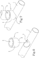
Figure 7 illustrates an assembled perspective view of a part of a radiant body according to the invention; -
Figure 8 illustrates a perspective view from below, with some parts in cross section, of the part of the radiant body ofFigures 6 and 7 ; -
Figures 9 and 10 illustrate, respectively, a side view in cross section and a top plan view of the part of the radiant body ofFigures 6 to 8 ; -
Figure 11 illustrates a perspective view from below of the bushing joint of the radiant body according to the invention. - As illustrated in the accompanying drawings, in particular
Figures 6 and 7 , a bushing joint, labelled 3, is used for the formation of radiant bodies, according to the invention, designed to increase or maintain a predetermined temperature in an environment by the passage of hot fluid. The accompanying drawings illustrate only a part of the radiant body, since the parts making up the radiant body are specular. - The radiant body comprises a first head and a second head, each composed of a main tubular conduit 1 (here, as stated, only one of the conduits is visible) having a corresponding longitudinal axis X of extension. The two main
tubular conduits 1 are positioned parallel to each other. - Each main
tubular conduit 1 has at least one radial hole or opening 2. - The radiant body comprises a
bushing 3 for joining each maintubular conduit 1. - Each
bushing 3 is associated with the corresponding maintubular conduit 1 at theradial opening 2. - Each
bushing 3 having an extension axis placed transversally to the longitudinal axis X of extension of the main tubular conduit (Figure 6 ). - The radiant body also comprises a secondary tubular conduit 4 (illustrated with a dashed line) associated, in a sealed fashion and at its ends, with the
corresponding bushing joints 3 so as to be positioned transversely with respect to the maintubular conduits 1 for the passage, in both directions, of a fluid between the two maintubular conduits 1. - The accompanying drawings illustrate a single main
tubular conduit 1, a radial hole or opening 2, a singlebushing joint 3 and a single secondarytubular conduit 4, since the upper parts of the radiant body are equal and the number of openings (and thus also the bushings used and relative secondary conduits) are obtained and positioned at regular intervals on each maintubular conduit 1 in a variable number as a function of the extension of the radiant body. - As illustrated (see
Figures 6 to 11 ), eachbushing joint 3 has afirst portion 5, external, having a cylindrical shape and asecond portion 6, internal, having a partly semi-spherical shape. - The
second portion 6 is configured for housing, at least partly, inside the corresponding maintubular conduit 1 through thecorresponding opening 2 in such a way as to form also a part of the outer surface of the maintubular conduit 1. - In other words, the bush is applied inside the radial opening and forms a part of the outer surface of the main tubular conduit.
- This geometrical architecture achieves a greater seal over time and a reduction both in the time for forming the radiant body and the overall final costs.
- Preferably, the
second portion 6 of eachbushing 3 has a first hemispherical stretch interrupted by a ring-shaped cut configured for interrupting the spherical shape of thesecond portion 6 and defining the free end forming the lower opening of thebushing 3 positioned, in use, completely inside the corresponding maintubular conduit 1. - Again preferably, each main
tubular conduit 1 has anopening 2 having the shape of a cradle. - In light of this, the partly
hemispherical portion 6 is coupled in an interlocking fashion in such a way as to define the external surface of the maintubular conduit 1 at least in the curved lateral stretches of the cradle-shaped opening 2. - It should be noted that each
bushing joint 3 has an annularinner seat 7 defined on its inner edge in a zone constituting the margin of separation between thecylindrical portion 5 and the partlyhemispherical portion 6, and defining also a part of the annular edge of a relative internal throughhole 8. - In light of this, a
seal gasket 9 is positioned, in use, in theannular seat 7. Eachbushing joint 3 has thecylindrical portion 5 equipped with an inner thread for coupling with the corresponding secondarytubular conduit 4. Preferably, the partlyhemispherical portion 6 is housed, in use, in the corresponding maintubular conduit 1 for at least a third of the inside diameter of the maintubular conduit 1. - In other words, the partly
hemispherical portion 6 is inserted inside the maintubular conduit 1 and penetrates for at least a third of the diameter, preferably at least half of the diameter of the main tubular conduit. - It should be noted that the edge of the
radial opening 2 and thebushing 3 are associated stably by means of an outer perimeter welding. - This type of welding is more secure and precise thanks to the outer undercut formed by the edge of the opening and by the portion of bushing housed therein.
- The invention provides a radiant body comprising at least:
- a first head and a second head, each composed of a main
tubular conduit 1 having a corresponding axis X of longitudinal extension; the maintubular conduits 1 are positioned parallel to each other; each maintubular conduit 1 has at least one radial hole oropening 2; - a
bushing joint 3 for each maintubular conduit 1; eachbushing 3 is associated with the corresponding maintubular conduit 1 at theradial opening 2; - a secondary
tubular conduit 4 associated, in a sealed fashion and at its ends, with the correspondingbushing joints 3 so as to be positioned transversely with respect to the maintubular conduits 1 for the passage, in both directions, of a fluid between the two maintubular conduits 1. - The radiant body comprises each bushing joint 3 having the features described above.
- The present aims are achieved with a bushing joint structured in this way. The hemispherical portion makes it possible to house in a precise, fast and secure manner the bushing joint on the tubular conduit without the need for mutual coaxial control operations.
- Each opening on the tubular conduit is obtained in a practical and fast manner and with reduced costs compared to traditional machining operations.
- The association by welding, with the hemispherical portion of the bushing which defines a part of the outer surface of the main tubular conduit guarantees a high level of security and duration over time.
Claims (6)
- A radiant body comprising at least:- a first head and a second head, each composed of a main tubular conduit (1) having a corresponding axis (X) of longitudinal extension; the main tubular conduits (1) being positioned parallel to each other; each main tubular conduit (1) having at least one radial hole or opening (2);- a bushing joint (3) for each main tubular conduit (1); each bushing (3) being associated with the corresponding main tubular conduit (1) at the radial opening (2); each bushing (3) having an extension axis placed transversally to the longitudinal axis (X) of extension of the main tubular conduit (1);- a secondary tubular conduit (4) associated, in a sealed fashion and at its ends, with the corresponding bushing joints (3) so as to be positioned transversely with respect to the main tubular conduits (1) for the passage, in both directions, of a fluid between the two main tubular conduits (1),characterised in that each bushing joint (3) has a first portion (5), external, having a cylindrical shape and a second portion (6), internal, having a partly semi-spherical shape; and the second portion (6) being configured for housing, at least partly, inside the corresponding main tubular conduit (1) through the corresponding opening (2) in such a way as to form also a part of the outer surface of the main tubular conduit (1).
- The radiant body according to claim 1, wherein the second portion (6) of each bushing (3) has a first hemispherical stretch interrupted by a ring-shaped cut configured for interrupting the spherical shape of the second portion (6) and defining the free end forming the lower opening of the bushing (3) positioned, in use, completely inside the corresponding main tubular conduit (1).
- The radiant body according to claim 1 or 2, wherein each main tubular conduit (1) has an opening (2) having the shape of a cradle wherein the partly hemispherical portion (6) is coupled in an interlocking fashion in such a way as to define the external surface of the main tubular conduit (1) at least in the curved lateral stretches of the cradle-shaped opening (2).
- The radiant body according to any one of the preceding claims, wherein each bushing joint (3) has an annular inner seat (7) defined on its inner edge in a zone constituting the margin of separation between the cylindrical portion (5) and the partly hemispherical portion (6), and defining also a part of the annular edge of a relative internal through hole (8); the annular seat (7) housing, in use, a seal gasket (9).
- The radiant body according to any one of the preceding claims, wherein each bushing joint (3) has the cylindrical portion (5) equipped with an inner thread for coupling with the corresponding secondary tubular conduit (4).
- The radiant body according to any one of the preceding claims, wherein the partly hemispherical portion (6) is housed, in use, in the corresponding main tubular conduit (1) for at least a third of the inside diameter of the main tubular conduit (1).
Priority Applications (3)
| Application Number | Priority Date | Filing Date | Title |
|---|---|---|---|
| SM20220029T SMT202200029T1 (en) | 2018-03-14 | 2019-03-12 | Radiant body |
| PL19162139T PL3540356T3 (en) | 2018-03-14 | 2019-03-12 | RADIATING BODY |
| SI201930157T SI3540356T1 (en) | 2018-03-14 | 2019-03-12 | Radiant body |
Applications Claiming Priority (1)
| Application Number | Priority Date | Filing Date | Title |
|---|---|---|---|
| IT102018000003546A IT201800003546A1 (en) | 2018-03-14 | 2018-03-14 | JUNCTION BUSH FOR THE FORMATION OF A RADIANT BODY. |
Publications (2)
| Publication Number | Publication Date |
|---|---|
| EP3540356A1 EP3540356A1 (en) | 2019-09-18 |
| EP3540356B1 true EP3540356B1 (en) | 2021-11-17 |
Family
ID=62530373
Family Applications (1)
| Application Number | Title | Priority Date | Filing Date |
|---|---|---|---|
| EP19162139.0A Active EP3540356B1 (en) | 2018-03-14 | 2019-03-12 | Radiant body |
Country Status (6)
| Country | Link |
|---|---|
| EP (1) | EP3540356B1 (en) |
| HU (1) | HUE057887T2 (en) |
| IT (1) | IT201800003546A1 (en) |
| PL (1) | PL3540356T3 (en) |
| SI (1) | SI3540356T1 (en) |
| SM (1) | SMT202200029T1 (en) |
Families Citing this family (1)
| Publication number | Priority date | Publication date | Assignee | Title |
|---|---|---|---|---|
| US12460761B1 (en) * | 2023-11-21 | 2025-11-04 | Ronald Drummer | Pipe-tapping system |
Family Cites Families (5)
| Publication number | Priority date | Publication date | Assignee | Title |
|---|---|---|---|---|
| US3064707A (en) * | 1959-09-30 | 1962-11-20 | Carrier Corp | Joining of tubular members |
| DE2434482C3 (en) * | 1974-07-18 | 1981-01-08 | Hans Berg Verwaltungs-Gmbh Und Co, Kg, 5226 Reichshof | Process for the production of a connection element for inlet and outlet pipes of plate radiators |
| GB1451869A (en) * | 1974-05-16 | 1976-10-06 | Berg Kg | Connector element' |
| DE3113207C2 (en) * | 1981-04-02 | 1986-01-02 | Harry 6472 Altenstadt König | Process for the manufacture of a connection part for the inlet and outlet line of panel heating elements |
| US5056704A (en) * | 1988-02-22 | 1991-10-15 | Tube Forming, Inc. | Tube fitting having a saddle bead with conforming pilot |
-
2018
- 2018-03-14 IT IT102018000003546A patent/IT201800003546A1/en unknown
-
2019
- 2019-03-12 HU HUE19162139A patent/HUE057887T2/en unknown
- 2019-03-12 PL PL19162139T patent/PL3540356T3/en unknown
- 2019-03-12 SM SM20220029T patent/SMT202200029T1/en unknown
- 2019-03-12 EP EP19162139.0A patent/EP3540356B1/en active Active
- 2019-03-12 SI SI201930157T patent/SI3540356T1/en unknown
Also Published As
| Publication number | Publication date |
|---|---|
| PL3540356T3 (en) | 2022-02-28 |
| HUE057887T2 (en) | 2022-06-28 |
| SI3540356T1 (en) | 2022-04-29 |
| EP3540356A1 (en) | 2019-09-18 |
| IT201800003546A1 (en) | 2019-09-14 |
| SMT202200029T1 (en) | 2022-03-21 |
Similar Documents
| Publication | Publication Date | Title |
|---|---|---|
| EP3296645B1 (en) | Fiberwound tanks | |
| RU2453434C2 (en) | Compensating element to connect structural parts | |
| US9080702B2 (en) | Method for the highly-thick thermal coating of joints by using electrofusion in pipes used for conducting fluids, made of steel tubes externally coated with polyolefins | |
| EP3030876B1 (en) | Pipe fittings allowing non-destructive pressure testing of integrity of seals | |
| US3727678A (en) | Heat transfer device useful for extruders | |
| KR101837909B1 (en) | Structure and method of pipe joint for dispensing fluid | |
| KR101550176B1 (en) | Shell and tube heat exchanger | |
| EP3540356A1 (en) | Bushing joint for forming a radiant body | |
| US10465942B2 (en) | Integrated water heater | |
| AU683987B2 (en) | Tank connector construction | |
| KR101550175B1 (en) | Welding method for shell and tube | |
| US3959058A (en) | Method and apparatus for butt-welding tubular plastic members to each other | |
| US10139128B2 (en) | Pressure tank for a water heater in stainless steel, and also a method for manufacture of a pressure tank | |
| CN112378085B (en) | Water storage device, water heater, and manufacturing method thereof | |
| US4365404A (en) | Making jacketed lined pipe | |
| US7188417B2 (en) | Advanced L-channel welded nozzle design | |
| CN105114724A (en) | Jacket flange | |
| CN215258474U (en) | Electric melting saddle type pipe fitting for gas pipeline | |
| CN215258473U (en) | Electric smelting saddle type pipe fitting | |
| AU683986B2 (en) | Method of fabricating a tank and method of fabricating a tank connector therefore | |
| JP6899900B2 (en) | Resin tube members, manufacturing methods for resin tube members, resin pipe fittings, and resin piping | |
| CN221525790U (en) | Electric smelting double socket welding combined pipe fitting | |
| JP7024956B2 (en) | Branch joints, branch construction methods, and branch joint manufacturing methods | |
| US4318441A (en) | Counterflow heat exchanger | |
| KR200487120Y1 (en) | heat exchanger |
Legal Events
| Date | Code | Title | Description |
|---|---|---|---|
| PUAI | Public reference made under article 153(3) epc to a published international application that has entered the european phase |
Free format text: ORIGINAL CODE: 0009012 |
|
| STAA | Information on the status of an ep patent application or granted ep patent |
Free format text: STATUS: THE APPLICATION HAS BEEN PUBLISHED |
|
| AK | Designated contracting states |
Kind code of ref document: A1 Designated state(s): AL AT BE BG CH CY CZ DE DK EE ES FI FR GB GR HR HU IE IS IT LI LT LU LV MC MK MT NL NO PL PT RO RS SE SI SK SM TR |
|
| AX | Request for extension of the european patent |
Extension state: BA ME |
|
| STAA | Information on the status of an ep patent application or granted ep patent |
Free format text: STATUS: REQUEST FOR EXAMINATION WAS MADE |
|
| 17P | Request for examination filed |
Effective date: 20200306 |
|
| RAV | Requested validation state of the european patent: fee paid |
Extension state: MD Effective date: 20200306 |
|
| RAX | Requested extension states of the european patent have changed |
Extension state: ME Payment date: 20200306 Extension state: BA Payment date: 20200306 |
|
| RBV | Designated contracting states (corrected) |
Designated state(s): AL AT BE BG CH CY CZ DE DK EE ES FI FR GB GR HR HU IE IS IT LI LT LU LV MC MK MT NL NO PL PT RO RS SE SI SK SM TR |
|
| GRAP | Despatch of communication of intention to grant a patent |
Free format text: ORIGINAL CODE: EPIDOSNIGR1 |
|
| STAA | Information on the status of an ep patent application or granted ep patent |
Free format text: STATUS: GRANT OF PATENT IS INTENDED |
|
| RIC1 | Information provided on ipc code assigned before grant |
Ipc: F28F 9/02 20060101AFI20210521BHEP Ipc: F16L 15/00 20060101ALI20210521BHEP Ipc: F28D 21/00 20060101ALI20210521BHEP Ipc: F28D 1/053 20060101ALI20210521BHEP Ipc: B21C 37/29 20060101ALI20210521BHEP Ipc: F28F 9/26 20060101ALI20210521BHEP Ipc: F28F 9/18 20060101ALI20210521BHEP Ipc: F24D 19/00 20060101ALI20210521BHEP Ipc: F16L 13/02 20060101ALI20210521BHEP Ipc: F16L 5/10 20060101ALI20210521BHEP Ipc: F16L 1/00 20060101ALI20210521BHEP Ipc: F16L 41/08 20060101ALI20210521BHEP |
|
| INTG | Intention to grant announced |
Effective date: 20210617 |
|
| RIN1 | Information on inventor provided before grant (corrected) |
Inventor name: LOLLI, VALTER |
|
| GRAS | Grant fee paid |
Free format text: ORIGINAL CODE: EPIDOSNIGR3 |
|
| GRAA | (expected) grant |
Free format text: ORIGINAL CODE: 0009210 |
|
| STAA | Information on the status of an ep patent application or granted ep patent |
Free format text: STATUS: THE PATENT HAS BEEN GRANTED |
|
| AK | Designated contracting states |
Kind code of ref document: B1 Designated state(s): AL AT BE BG CH CY CZ DE DK EE ES FI FR GB GR HR HU IE IS IT LI LT LU LV MC MK MT NL NO PL PT RO RS SE SI SK SM TR |
|
| REG | Reference to a national code |
Ref country code: GB Ref legal event code: FG4D |
|
| REG | Reference to a national code |
Ref country code: DE Ref legal event code: R096 Ref document number: 602019009259 Country of ref document: DE |
|
| REG | Reference to a national code |
Ref country code: IE Ref legal event code: FG4D |
|
| REG | Reference to a national code |
Ref country code: AT Ref legal event code: REF Ref document number: 1448389 Country of ref document: AT Kind code of ref document: T Effective date: 20211215 |
|
| REG | Reference to a national code |
Ref country code: RO Ref legal event code: EPE |
|
| REG | Reference to a national code |
Ref country code: LT Ref legal event code: MG9D |
|
| REG | Reference to a national code |
Ref country code: NL Ref legal event code: MP Effective date: 20211117 |
|
| REG | Reference to a national code |
Ref country code: AT Ref legal event code: MK05 Ref document number: 1448389 Country of ref document: AT Kind code of ref document: T Effective date: 20211117 |
|
| PG25 | Lapsed in a contracting state [announced via postgrant information from national office to epo] |
Ref country code: RS Free format text: LAPSE BECAUSE OF FAILURE TO SUBMIT A TRANSLATION OF THE DESCRIPTION OR TO PAY THE FEE WITHIN THE PRESCRIBED TIME-LIMIT Effective date: 20211117 Ref country code: LT Free format text: LAPSE BECAUSE OF FAILURE TO SUBMIT A TRANSLATION OF THE DESCRIPTION OR TO PAY THE FEE WITHIN THE PRESCRIBED TIME-LIMIT Effective date: 20211117 Ref country code: FI Free format text: LAPSE BECAUSE OF FAILURE TO SUBMIT A TRANSLATION OF THE DESCRIPTION OR TO PAY THE FEE WITHIN THE PRESCRIBED TIME-LIMIT Effective date: 20211117 Ref country code: AT Free format text: LAPSE BECAUSE OF FAILURE TO SUBMIT A TRANSLATION OF THE DESCRIPTION OR TO PAY THE FEE WITHIN THE PRESCRIBED TIME-LIMIT Effective date: 20211117 |
|
| REG | Reference to a national code |
Ref country code: SK Ref legal event code: T3 Ref document number: E 39141 Country of ref document: SK |
|
| PG25 | Lapsed in a contracting state [announced via postgrant information from national office to epo] |
Ref country code: IS Free format text: LAPSE BECAUSE OF FAILURE TO SUBMIT A TRANSLATION OF THE DESCRIPTION OR TO PAY THE FEE WITHIN THE PRESCRIBED TIME-LIMIT Effective date: 20220317 Ref country code: SE Free format text: LAPSE BECAUSE OF FAILURE TO SUBMIT A TRANSLATION OF THE DESCRIPTION OR TO PAY THE FEE WITHIN THE PRESCRIBED TIME-LIMIT Effective date: 20211117 Ref country code: PT Free format text: LAPSE BECAUSE OF FAILURE TO SUBMIT A TRANSLATION OF THE DESCRIPTION OR TO PAY THE FEE WITHIN THE PRESCRIBED TIME-LIMIT Effective date: 20220317 Ref country code: NO Free format text: LAPSE BECAUSE OF FAILURE TO SUBMIT A TRANSLATION OF THE DESCRIPTION OR TO PAY THE FEE WITHIN THE PRESCRIBED TIME-LIMIT Effective date: 20220217 Ref country code: NL Free format text: LAPSE BECAUSE OF FAILURE TO SUBMIT A TRANSLATION OF THE DESCRIPTION OR TO PAY THE FEE WITHIN THE PRESCRIBED TIME-LIMIT Effective date: 20211117 Ref country code: LV Free format text: LAPSE BECAUSE OF FAILURE TO SUBMIT A TRANSLATION OF THE DESCRIPTION OR TO PAY THE FEE WITHIN THE PRESCRIBED TIME-LIMIT Effective date: 20211117 Ref country code: HR Free format text: LAPSE BECAUSE OF FAILURE TO SUBMIT A TRANSLATION OF THE DESCRIPTION OR TO PAY THE FEE WITHIN THE PRESCRIBED TIME-LIMIT Effective date: 20211117 Ref country code: GR Free format text: LAPSE BECAUSE OF FAILURE TO SUBMIT A TRANSLATION OF THE DESCRIPTION OR TO PAY THE FEE WITHIN THE PRESCRIBED TIME-LIMIT Effective date: 20220218 Ref country code: ES Free format text: LAPSE BECAUSE OF FAILURE TO SUBMIT A TRANSLATION OF THE DESCRIPTION OR TO PAY THE FEE WITHIN THE PRESCRIBED TIME-LIMIT Effective date: 20211117 |
|
| REG | Reference to a national code |
Ref country code: HU Ref legal event code: AG4A Ref document number: E057887 Country of ref document: HU |
|
| PG25 | Lapsed in a contracting state [announced via postgrant information from national office to epo] |
Ref country code: EE Free format text: LAPSE BECAUSE OF FAILURE TO SUBMIT A TRANSLATION OF THE DESCRIPTION OR TO PAY THE FEE WITHIN THE PRESCRIBED TIME-LIMIT Effective date: 20211117 Ref country code: DK Free format text: LAPSE BECAUSE OF FAILURE TO SUBMIT A TRANSLATION OF THE DESCRIPTION OR TO PAY THE FEE WITHIN THE PRESCRIBED TIME-LIMIT Effective date: 20211117 |
|
| VS25 | Lapsed in a validation state [announced via postgrant information from nat. office to epo] |
Ref country code: MD Free format text: LAPSE BECAUSE OF FAILURE TO SUBMIT A TRANSLATION OF THE DESCRIPTION OR TO PAY THE FEE WITHIN THE PRESCRIBED TIME-LIMIT Effective date: 20211117 |
|
| REG | Reference to a national code |
Ref country code: DE Ref legal event code: R097 Ref document number: 602019009259 Country of ref document: DE |
|
| PLBE | No opposition filed within time limit |
Free format text: ORIGINAL CODE: 0009261 |
|
| STAA | Information on the status of an ep patent application or granted ep patent |
Free format text: STATUS: NO OPPOSITION FILED WITHIN TIME LIMIT |
|
| 26N | No opposition filed |
Effective date: 20220818 |
|
| PG25 | Lapsed in a contracting state [announced via postgrant information from national office to epo] |
Ref country code: MC Free format text: LAPSE BECAUSE OF FAILURE TO SUBMIT A TRANSLATION OF THE DESCRIPTION OR TO PAY THE FEE WITHIN THE PRESCRIBED TIME-LIMIT Effective date: 20211117 |
|
| REG | Reference to a national code |
Ref country code: CH Ref legal event code: PL |
|
| REG | Reference to a national code |
Ref country code: BE Ref legal event code: MM Effective date: 20220331 |
|
| PG25 | Lapsed in a contracting state [announced via postgrant information from national office to epo] |
Ref country code: LU Free format text: LAPSE BECAUSE OF NON-PAYMENT OF DUE FEES Effective date: 20220312 Ref country code: LI Free format text: LAPSE BECAUSE OF NON-PAYMENT OF DUE FEES Effective date: 20220331 Ref country code: IE Free format text: LAPSE BECAUSE OF NON-PAYMENT OF DUE FEES Effective date: 20220312 Ref country code: CH Free format text: LAPSE BECAUSE OF NON-PAYMENT OF DUE FEES Effective date: 20220331 |
|
| PG25 | Lapsed in a contracting state [announced via postgrant information from national office to epo] |
Ref country code: BE Free format text: LAPSE BECAUSE OF NON-PAYMENT OF DUE FEES Effective date: 20220331 |
|
| P01 | Opt-out of the competence of the unified patent court (upc) registered |
Effective date: 20230519 |
|
| PG25 | Lapsed in a contracting state [announced via postgrant information from national office to epo] |
Ref country code: MK Free format text: LAPSE BECAUSE OF FAILURE TO SUBMIT A TRANSLATION OF THE DESCRIPTION OR TO PAY THE FEE WITHIN THE PRESCRIBED TIME-LIMIT Effective date: 20211117 Ref country code: CY Free format text: LAPSE BECAUSE OF FAILURE TO SUBMIT A TRANSLATION OF THE DESCRIPTION OR TO PAY THE FEE WITHIN THE PRESCRIBED TIME-LIMIT Effective date: 20211117 |
|
| PG25 | Lapsed in a contracting state [announced via postgrant information from national office to epo] |
Ref country code: MT Free format text: LAPSE BECAUSE OF FAILURE TO SUBMIT A TRANSLATION OF THE DESCRIPTION OR TO PAY THE FEE WITHIN THE PRESCRIBED TIME-LIMIT Effective date: 20211117 |
|
| PGFP | Annual fee paid to national office [announced via postgrant information from national office to epo] |
Ref country code: AL Payment date: 20250327 Year of fee payment: 7 |
|
| PGFP | Annual fee paid to national office [announced via postgrant information from national office to epo] |
Ref country code: SM Payment date: 20260212 Year of fee payment: 8 |
|
| PGFP | Annual fee paid to national office [announced via postgrant information from national office to epo] |
Ref country code: GB Payment date: 20260304 Year of fee payment: 8 |
|
| PGFP | Annual fee paid to national office [announced via postgrant information from national office to epo] |
Ref country code: DE Payment date: 20260320 Year of fee payment: 8 |
|
| PGFP | Annual fee paid to national office [announced via postgrant information from national office to epo] |
Ref country code: RO Payment date: 20260220 Year of fee payment: 8 Ref country code: IT Payment date: 20260319 Year of fee payment: 8 |
|
| PGFP | Annual fee paid to national office [announced via postgrant information from national office to epo] |
Ref country code: HU Payment date: 20260226 Year of fee payment: 8 |
|
| PGFP | Annual fee paid to national office [announced via postgrant information from national office to epo] |
Ref country code: FR Payment date: 20260323 Year of fee payment: 8 |
|
| PGFP | Annual fee paid to national office [announced via postgrant information from national office to epo] |
Ref country code: TR Payment date: 20260223 Year of fee payment: 8 |
|
| PGFP | Annual fee paid to national office [announced via postgrant information from national office to epo] |
Ref country code: CZ Payment date: 20260226 Year of fee payment: 8 |
|
| PGFP | Annual fee paid to national office [announced via postgrant information from national office to epo] |
Ref country code: PL Payment date: 20260219 Year of fee payment: 8 |
|
| PGFP | Annual fee paid to national office [announced via postgrant information from national office to epo] |
Ref country code: SK Payment date: 20260213 Year of fee payment: 8 |
|
| PGFP | Annual fee paid to national office [announced via postgrant information from national office to epo] |
Ref country code: SI Payment date: 20260219 Year of fee payment: 8 |
|
| PGFP | Annual fee paid to national office [announced via postgrant information from national office to epo] |
Ref country code: BG Payment date: 20260323 Year of fee payment: 8 |