EP3540326A1 - Electric heater - Google Patents
Electric heater Download PDFInfo
- Publication number
- EP3540326A1 EP3540326A1 EP18161958.6A EP18161958A EP3540326A1 EP 3540326 A1 EP3540326 A1 EP 3540326A1 EP 18161958 A EP18161958 A EP 18161958A EP 3540326 A1 EP3540326 A1 EP 3540326A1
- Authority
- EP
- European Patent Office
- Prior art keywords
- elements
- heating
- contact sheet
- metallic contact
- electric
- Prior art date
- Legal status (The legal status is an assumption and is not a legal conclusion. Google has not performed a legal analysis and makes no representation as to the accuracy of the status listed.)
- Withdrawn
Links
Images

Classifications
-
- F—MECHANICAL ENGINEERING; LIGHTING; HEATING; WEAPONS; BLASTING
- F24—HEATING; RANGES; VENTILATING
- F24H—FLUID HEATERS, e.g. WATER OR AIR HEATERS, HAVING HEAT-GENERATING MEANS, e.g. HEAT PUMPS, IN GENERAL
- F24H3/00—Air heaters
- F24H3/02—Air heaters with forced circulation
- F24H3/04—Air heaters with forced circulation the air being in direct contact with the heating medium, e.g. electric heating element
- F24H3/0405—Air heaters with forced circulation the air being in direct contact with the heating medium, e.g. electric heating element using electric energy supply, e.g. the heating medium being a resistive element; Heating by direct contact, i.e. with resistive elements, electrodes and fins being bonded together without additional element in-between
- F24H3/0429—For vehicles
- F24H3/0441—Interfaces between the electrodes of a resistive heating element and the power supply means
-
- B—PERFORMING OPERATIONS; TRANSPORTING
- B60—VEHICLES IN GENERAL
- B60H—ARRANGEMENTS OF HEATING, COOLING, VENTILATING OR OTHER AIR-TREATING DEVICES SPECIALLY ADAPTED FOR PASSENGER OR GOODS SPACES OF VEHICLES
- B60H1/00—Heating, cooling or ventilating [HVAC] devices
- B60H1/22—Heating, cooling or ventilating [HVAC] devices the heat being derived otherwise than from the propulsion plant
- B60H1/2215—Heating, cooling or ventilating [HVAC] devices the heat being derived otherwise than from the propulsion plant the heat being derived from electric heaters
- B60H1/2225—Heating, cooling or ventilating [HVAC] devices the heat being derived otherwise than from the propulsion plant the heat being derived from electric heaters arrangements of electric heaters for heating air
-
- F—MECHANICAL ENGINEERING; LIGHTING; HEATING; WEAPONS; BLASTING
- F24—HEATING; RANGES; VENTILATING
- F24H—FLUID HEATERS, e.g. WATER OR AIR HEATERS, HAVING HEAT-GENERATING MEANS, e.g. HEAT PUMPS, IN GENERAL
- F24H9/00—Details
- F24H9/18—Arrangement or mounting of grates or heating means
- F24H9/1854—Arrangement or mounting of grates or heating means for air heaters
- F24H9/1863—Arrangement or mounting of electric heating means
-
- H—ELECTRICITY
- H05—ELECTRIC TECHNIQUES NOT OTHERWISE PROVIDED FOR
- H05B—ELECTRIC HEATING; ELECTRIC LIGHT SOURCES NOT OTHERWISE PROVIDED FOR; CIRCUIT ARRANGEMENTS FOR ELECTRIC LIGHT SOURCES, IN GENERAL
- H05B3/00—Ohmic-resistance heating
- H05B3/20—Heating elements having extended surface area substantially in a two-dimensional plane, e.g. plate-heater
- H05B3/22—Heating elements having extended surface area substantially in a two-dimensional plane, e.g. plate-heater non-flexible
- H05B3/24—Heating elements having extended surface area substantially in a two-dimensional plane, e.g. plate-heater non-flexible heating conductor being self-supporting
-
- H—ELECTRICITY
- H05—ELECTRIC TECHNIQUES NOT OTHERWISE PROVIDED FOR
- H05B—ELECTRIC HEATING; ELECTRIC LIGHT SOURCES NOT OTHERWISE PROVIDED FOR; CIRCUIT ARRANGEMENTS FOR ELECTRIC LIGHT SOURCES, IN GENERAL
- H05B2203/00—Aspects relating to Ohmic resistive heating covered by group H05B3/00
- H05B2203/022—Heaters specially adapted for heating gaseous material
- H05B2203/023—Heaters of the type used for electrically heating the air blown in a vehicle compartment by the vehicle heating system
Definitions
- the invention relates to an electric heater, in particular for a heating or an air-conditioning system of a motor vehicle, comprising a heater core having a plurality of heating units, said heating units having at least one electric heating element arranged between metallic contact sheet elements, wherein the metallic contact sheet elements are electrically contacting the at least one electric heating element to allow an electric current flow through the heating elements.
- Electric heaters are well known in the art especially for the use in a heating or an air-conditioning system of a motor vehicle.
- the electric heater is used for example to heat up an air flow generated by a fan of the heating or the air-conditioning system.
- Such an electric heater often comprises a plurality of heating units which respectively contain at least one electric heating element.
- the heating units are located in an arrangement together with heat dissipating fins and metallic contact sheet elements contacting the electric heating elements.
- the metallic sheet elements are connected to the heating elements and furthermore they are connected to a power source to provide the electric current to heat the heating elements due to the electric current. This leads to a great number of electric contacts between each of the metallic contact sheet elements and the power source leading to a number of electric transition resistances decreasing the performance of the electric heater.
- an electric heater in particular for a heating or an air-conditioning system of a motor vehicle, comprising a heater core having a plurality of heating units, said heating units having at least one electric heating element arranged between metallic contact sheet elements, wherein the metallic contact sheet elements are electrically contacting the at least one electric heating element to allow an electric current flow through the heating elements, wherein at least two contact rails are provided such that each of the metallic contact sheet elements is mechanically and electrically connected to one of the contact rails, which both have a contact means to contact the contact rails to a power source. Therefore, a secure and stable electrical and mechanical contact is provided without the high number of contact means to contact the power source.
- the metallic contact sheet elements are mechanically connected to the respective contact rail by means of clinching. This allows a durable and secure mechanical connection realized by an easy connection process.
- Another embodiment shows that a plurality of heating units is provided which comprise metallic contact sheet elements wherein the metallic contact sheet elements of the plurality of heating units are arranged parallel to each other. Therefore, a structure is provided which is light and doesn't need to much space.
- each of the heating units having a first metallic contact sheet element and a second metallic contact sheet element, wherein the first metallic contact sheet elements are connected to a first contact rail and the second metallic contact sheet elements are connected to the second contact rail. Therefore, a clear structure is provided allowing a stable and durable mechanical structure.
- first metallic contact sheet elements are arranged in a first plane and the second metallic contact sheet elements are located in a second plane, the second plane is spaced apart from the first plane and arranged parallel to the first plane. This allows a small packaging of the heating units.
- the contact means are aligned perpendicular to the metallic contact sheet elements. Therefore, an easy connection process is possible by connecting the contact means to respective counter contact means of a power source.
- the contact means are aligned parallel to the contact rails. Therefore, the contact direction in which the contact means are pushed against the counter contact means is in the direction of the length direction of the contact rails.
- the object is furthermore achieved by the features of claim 8.
- an electric heater in particular for a heating or an air-conditioning system of a motor vehicle, comprising a heater core having at least one or a plurality of heating units, said heating unit has a plurality of electric heating elements arranged between metallic contact sheet elements, wherein the metallic contact sheet elements are electrically contacting the at least one electric heating element to allow an electric current flow through the heating elements, characterised in that the heating elements are arranged in a two-dimensional pattern, wherein the metallic contact sheet elements are contacting all the heating elements of a heating unit, wherein the metallic contact sheet elements have a contact means to contact a power source.
- This allows a structure with only a small number of electrical contacts. Therefore, the contact resistance is small due to the reduced number of such contacts.
- the metallic contact sheet elements are mechanically connected to the respective contact means by means of clinching. This allows a durable mechanical connection and a good electrical connection.
- the heating elements are arranged in a rectangular pattern having rows and columns of heating elements. This allows an effective arrangement of the heating elements.
- a plurality of heating elements arranged in a two-dimensional pattern is contacted on both sides by a contact sheet respectively.
- a plurality of heating units which comprise metallic contact sheet elements wherein the metallic contact sheet elements of the plurality of heating units are arranged parallel to each other. This allows a compact arrangement of the unit.
- a first metallic contact sheet element is arranged in a first plane and a second metallic contact sheet element is located in a second plane, the second plane is spaced apart from the first plane and arranged parallel to the first plane.
- the contact means are aligned perpendicular to rows of heating elements. This allows a small unit which is easy to connect.
- Figure 1 shows a side view of a heating unit 3 of a heater core 2 of an electric heater 1, according to an embodiment of the present invention.
- Figure 2 shows a plan view of the heating unit 3 according to Figure 1 .
- the inventive electric heater 1 might be for example utilised in a heating or an air-conditioning system of a motor vehicle, In this case the electric heater 1 heats up air, which passes the heat transfer surface of the electric heater 1 in order to supply warm air to the passenger compartment of the motor vehicle. In an alternative embodiment the electric heater may heat a liquid or another gas.
- the electric heater 1 is typically arranged in an air duct of the housing of the heating or the air-conditioning system. Structurally, the electric heater 1 comprises a heater core 2.
- the heater core 2 features a plurality of heating units 3. The number and size of the heating units 3 can vary in different embodiments.
- the Figures 1 and 2 show a heating unit 3 having at least one electric heating element 4 arranged between metallic contact sheet elements 5.
- the metallic contact sheet elements 5 are electrically contacting the at least one electric heating element 4 to allow an electric current flow through the heating elements in order to heat the electric heating elements 4.
- the electric heating elements 4 are arranged in one row having four electric heating elements 4.
- the metallic contact sheet elements 5 are located on adjacent side faces of the electric heating elements 4 to connect adjacent side faces of the respective electric heating element allowing a current flow through the heating element 4.
- the metallic contact sheet elements 5 are arranged such that each metallic contact sheet elements 5 projects on one side of the heating unit 3 from the electric heating elements 4 such that it generates a free end 6 to create an area to connect the heating unit 3 to a contact rail or to a power source.
- Figure 3 shows a side view of an embodiment of a heating unit 3 of a heater core 2 of an electric heater 1, according to an embodiment of the present invention.
- Figure 4 shows a plan view of the heating unit 3 according to Figure 3 .
- the inventive electric heater 1 might be for example utilised in a heating or an air-conditioning system of a motor vehicle. In this case the electric heater 1 heats up air, which passes the heat transfer surface of the electric heater 1 in order to supply warm air to the passenger compartment of the motor vehicle. In an alternative embodiment the electric heater 1 may heat a liquid or another gas.
- the electric heater 1 is typically arranged in an air duct of the housing of the heating or the air-conditioning system. Structurally, the electric heater 1 comprises a heater core 2.
- the heater core 2 features a plurality of heating units 3. The number and size of the heating units 3 can vary in different embodiments.
- the Figures 3 and 4 show a unit having four heating units 3 each having four electric heating elements 4 arranged between metallic contact sheet elements 5.
- the metallic contact sheet elements 5 are electrically contacting the at least one electric heating element 4 to allow an electric current flow through the heating elements in order to heat the electric heating elements 4.
- the electric heating elements 4 of a heating unit 3 are arranged in one row having four electric heating elements 4.
- the metallic contact sheet elements 5 are located on adjacent side faces of the electric heating elements 4 to connect adjacent side faces of the respective electric heating element 4 allowing a current flow through the electric heating element 4.
- the metallic contact sheet elements 5 are arranged such that each metallic contact sheet element 5 projects on one side of the heating unit 3 from the electric heating elements 4 such that it generates a free end 6 to create an area to connect the heating unit 3 to a contact rail 7 or to a power source.
- each of the heating units 3 is connected on one side to one contact rail 7 and on the other side to the other contact rail 7.
- each of the metallic contact sheet elements 5 is mechanically and electrically connected to one of the contact rails 7, which both have a contact means 8 to contact the contact rails 7 to a power source.
- the contact means 8 are arranged as plug or connector.
- the metallic contact sheet elements 5 are mechanically and electrically connected to the respective contact rail 7 by means of clinching. Additionally, the contact means 8 are possibly connected to the contact rails 7 by clinching.
- FIG. 3 and 4 shows that a plurality of heating units 3 is provided which comprise metallic contact sheet elements 5 to contact the electric heating elements 4 wherein the metallic contact sheet elements 5 of the plurality of heating units 3 are arranged parallel to each other.
- Each of the heating units 3 have a first metallic contact sheet element 5 and a second metallic contact sheet element 5, wherein the first metallic contact sheet elements 5 are connected to a first contact rail 7 and the second metallic contact sheet elements 5 are connected to a second contact rail 7 adjacent to the first contact rail 7.
- the first metallic contact sheet elements 5 are arranged in a first plane and the second metallic contact sheet elements 5 are located in a second plane, the second plane is spaced apart from the first plane by the electric heating elements 4 and they are arranged parallel to the first plane. Therefore, the unit shows a flat structure.
- the contact means 8 are aligned perpendicular to the metallic contact sheet elements 5 i.e. the length direction of the metallic contact sheet elements 5. This means that the length direction of the contact means 8 are aligned perpendicular to the length direction of the metallic contact sheet elements 5.
- the contact means 8 are aligned parallel to the contact rails 7. This means that the length direction of the contact means 8 are aligned parallel to the length direction of the contact rails 7.
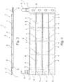
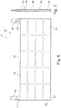
- Figure 5 shows a side view of another embodiment of a heating unit 23 of a heater core 22 of an electric heater 21, according to an embodiment of the present invention.
- Figure 6 shows a plan view of the heating unit 23 according to Figure 5 .
- Figures 5 and 6 show an electric heater 21, in particular for a heating or an air-conditioning system of a motor vehicle, comprising a heater core 22 having at least one or a plurality of heating units 23.
- the heating unit 23 has a plurality of electric heating elements 24 arranged between metallic contact sheet elements 25, wherein the metallic contact sheet elements 25 are electrically contacting the at least one electric heating element 24 or the heating elements 24 to allow an electric current flow through the electric heating elements 24.
- the electric heating elements 24 are arranged in a two-dimensional pattern. Especially the electric heating elements 24 are arranged in a rectangular pattern having rows 26 and columns 27 of electric heating elements 24. Therefore, the number of electric heating elements 24 may vary to create a respective heating unit 23.
- the metallic contact sheet elements 25 are contacting all the electric heating elements 24 of a heating unit 23, wherein the metallic contact sheet elements 25 have a contact means 28 to contact a power source. Therefore, the metallic contact sheet elements 25 are contacting the heating elements 23 as they are arranged in the two-dimensional pattern.
- An electric heater 21 according to the invention may have a plurality of heating units 23 which comprise metallic contact sheet elements 25 wherein the metallic contact sheet elements 25 of the plurality of heating units 23 are arranged parallel to each other.
- a first metallic contact sheet element 25 is arranged in a first plane and a second metallic contact sheet element 25 is located in a second plane, the second plane is spaced apart from the first plane due to the electric heating elements 24 and arranged parallel to the first plane.
- the contact means 28 are aligned perpendicular to rows 26 of electric heating elements 24. This means that the length direction of the contact means 28 is arranged perpendicular to a row 26 of electric heating elements 24 which is parallel to a length direction of the metallic contact sheet element 25.
Landscapes
- Engineering & Computer Science (AREA)
- Physics & Mathematics (AREA)
- Thermal Sciences (AREA)
- Mechanical Engineering (AREA)
- Chemical & Material Sciences (AREA)
- Combustion & Propulsion (AREA)
- General Engineering & Computer Science (AREA)
- Air-Conditioning For Vehicles (AREA)
Abstract
Description
- The invention relates to an electric heater, in particular for a heating or an air-conditioning system of a motor vehicle, comprising a heater core having a plurality of heating units, said heating units having at least one electric heating element arranged between metallic contact sheet elements, wherein the metallic contact sheet elements are electrically contacting the at least one electric heating element to allow an electric current flow through the heating elements.
- Electric heaters are well known in the art especially for the use in a heating or an air-conditioning system of a motor vehicle. The electric heater is used for example to heat up an air flow generated by a fan of the heating or the air-conditioning system. Such an electric heater often comprises a plurality of heating units which respectively contain at least one electric heating element. The heating units are located in an arrangement together with heat dissipating fins and metallic contact sheet elements contacting the electric heating elements.
- The metallic sheet elements are connected to the heating elements and furthermore they are connected to a power source to provide the electric current to heat the heating elements due to the electric current. This leads to a great number of electric contacts between each of the metallic contact sheet elements and the power source leading to a number of electric transition resistances decreasing the performance of the electric heater.
- Therefore, it is the object of the invention to provide an electric heater which is improved with respect to transitional resistances.
- The object is achieved by the features of claim 1.
- According to an embodiment an electric heater is provided, in particular for a heating or an air-conditioning system of a motor vehicle, comprising a heater core having a plurality of heating units, said heating units having at least one electric heating element arranged between metallic contact sheet elements, wherein the metallic contact sheet elements are electrically contacting the at least one electric heating element to allow an electric current flow through the heating elements, wherein at least two contact rails are provided such that each of the metallic contact sheet elements is mechanically and electrically connected to one of the contact rails, which both have a contact means to contact the contact rails to a power source. Therefore, a secure and stable electrical and mechanical contact is provided without the high number of contact means to contact the power source.
- According to an embodiment, it is of advantage that the metallic contact sheet elements are mechanically connected to the respective contact rail by means of clinching. This allows a durable and secure mechanical connection realized by an easy connection process.
- Another embodiment shows that a plurality of heating units is provided which comprise metallic contact sheet elements wherein the metallic contact sheet elements of the plurality of heating units are arranged parallel to each other. Therefore, a structure is provided which is light and doesn't need to much space.
- Furthermore, it is of advantage that each of the heating units having a first metallic contact sheet element and a second metallic contact sheet element, wherein the first metallic contact sheet elements are connected to a first contact rail and the second metallic contact sheet elements are connected to the second contact rail. Therefore, a clear structure is provided allowing a stable and durable mechanical structure.
- Another embodiment shows that the first metallic contact sheet elements are arranged in a first plane and the second metallic contact sheet elements are located in a second plane, the second plane is spaced apart from the first plane and arranged parallel to the first plane. This allows a small packaging of the heating units.
- Furthermore, it is of advantage that the contact means are aligned perpendicular to the metallic contact sheet elements. Therefore, an easy connection process is possible by connecting the contact means to respective counter contact means of a power source.
- In order to achieve an easy connectable heating unit the contact means are aligned parallel to the contact rails. Therefore, the contact direction in which the contact means are pushed against the counter contact means is in the direction of the length direction of the contact rails.
- The object is furthermore achieved by the features of
claim 8. - According to an embodiment an electric heater is provided, in particular for a heating or an air-conditioning system of a motor vehicle, comprising a heater core having at least one or a plurality of heating units, said heating unit has a plurality of electric heating elements arranged between metallic contact sheet elements, wherein the metallic contact sheet elements are electrically contacting the at least one electric heating element to allow an electric current flow through the heating elements, characterised in that the heating elements are arranged in a two-dimensional pattern, wherein the metallic contact sheet elements are contacting all the heating elements of a heating unit, wherein the metallic contact sheet elements have a contact means to contact a power source. This allows a structure with only a small number of electrical contacts. Therefore, the contact resistance is small due to the reduced number of such contacts.
- It is of advantage that the metallic contact sheet elements are mechanically connected to the respective contact means by means of clinching. This allows a durable mechanical connection and a good electrical connection.
- It is of advantage that the heating elements are arranged in a rectangular pattern having rows and columns of heating elements. This allows an effective arrangement of the heating elements. A plurality of heating elements arranged in a two-dimensional pattern is contacted on both sides by a contact sheet respectively.
- Furthermore, it is of advantage that a plurality of heating units is provided which comprise metallic contact sheet elements wherein the metallic contact sheet elements of the plurality of heating units are arranged parallel to each other. This allows a compact arrangement of the unit.
- Furthermore, it is of advantage that a first metallic contact sheet element is arranged in a first plane and a second metallic contact sheet element is located in a second plane, the second plane is spaced apart from the first plane and arranged parallel to the first plane.
- According to another embodiment of the invention it is of advantage that the contact means are aligned perpendicular to rows of heating elements. This allows a small unit which is easy to connect.
- Further preferable features and embodiments of the invention are described in the claims and the following description of the drawings.
- The invention is explained in detail below by means of an exemplary embodiment and with reference to the drawings, in which:
- Figure 1
- shows a side view of a heating unit of an electrical heater,
- Figure 2
- shows a plan view of the heating unit according to
Figure 1 , - Figure 3
- shows a side view of a heating unit of an electrical heater,
- Figure 4
- shows a plan view of the heating unit according to
Figure 3 , - Figure 5
- shows a side view of a heating unit of an electrical heater, and
- Figure 6
- shows a plan view of the heating unit according to
Figure 5 . -
Figure 1 shows a side view of aheating unit 3 of aheater core 2 of an electric heater 1, according to an embodiment of the present invention.Figure 2 shows a plan view of theheating unit 3 according toFigure 1 . - The inventive electric heater 1 might be for example utilised in a heating or an air-conditioning system of a motor vehicle, In this case the electric heater 1 heats up air, which passes the heat transfer surface of the electric heater 1 in order to supply warm air to the passenger compartment of the motor vehicle. In an alternative embodiment the electric heater may heat a liquid or another gas.
- The electric heater 1 is typically arranged in an air duct of the housing of the heating or the air-conditioning system. Structurally, the electric heater 1 comprises a
heater core 2. Theheater core 2 features a plurality ofheating units 3. The number and size of theheating units 3 can vary in different embodiments. - The
Figures 1 and 2 show aheating unit 3 having at least oneelectric heating element 4 arranged between metalliccontact sheet elements 5. The metalliccontact sheet elements 5 are electrically contacting the at least oneelectric heating element 4 to allow an electric current flow through the heating elements in order to heat theelectric heating elements 4. - As can be seen in
Figures 1 and 2 theelectric heating elements 4 are arranged in one row having fourelectric heating elements 4. The metalliccontact sheet elements 5 are located on adjacent side faces of theelectric heating elements 4 to connect adjacent side faces of the respective electric heating element allowing a current flow through theheating element 4. As can be seen inFigure 1 the metalliccontact sheet elements 5 are arranged such that each metalliccontact sheet elements 5 projects on one side of theheating unit 3 from theelectric heating elements 4 such that it generates afree end 6 to create an area to connect theheating unit 3 to a contact rail or to a power source. -
Figure 3 shows a side view of an embodiment of aheating unit 3 of aheater core 2 of an electric heater 1, according to an embodiment of the present invention.Figure 4 shows a plan view of theheating unit 3 according toFigure 3 . - The inventive electric heater 1 might be for example utilised in a heating or an air-conditioning system of a motor vehicle. In this case the electric heater 1 heats up air, which passes the heat transfer surface of the electric heater 1 in order to supply warm air to the passenger compartment of the motor vehicle. In an alternative embodiment the electric heater 1 may heat a liquid or another gas.
- The electric heater 1 is typically arranged in an air duct of the housing of the heating or the air-conditioning system. Structurally, the electric heater 1 comprises a
heater core 2. Theheater core 2 features a plurality ofheating units 3. The number and size of theheating units 3 can vary in different embodiments. - The
Figures 3 and 4 show a unit having fourheating units 3 each having fourelectric heating elements 4 arranged between metalliccontact sheet elements 5. The metalliccontact sheet elements 5 are electrically contacting the at least oneelectric heating element 4 to allow an electric current flow through the heating elements in order to heat theelectric heating elements 4. - As can be seen in
Figures 3 and 4 theelectric heating elements 4 of aheating unit 3 are arranged in one row having fourelectric heating elements 4. The metalliccontact sheet elements 5 are located on adjacent side faces of theelectric heating elements 4 to connect adjacent side faces of the respectiveelectric heating element 4 allowing a current flow through theelectric heating element 4. As can be seen inFigure 3 the metalliccontact sheet elements 5 are arranged such that each metalliccontact sheet element 5 projects on one side of theheating unit 3 from theelectric heating elements 4 such that it generates afree end 6 to create an area to connect theheating unit 3 to acontact rail 7 or to a power source. - On both sides of the unit contact rails 7 are provided being arranged perpendicular to the length direction of the
heating unit 3. Therefore, each of theheating units 3 is connected on one side to onecontact rail 7 and on the other side to theother contact rail 7. - Accordingly, at least two
contact rails 7 are provided such that each of the metalliccontact sheet elements 5 is mechanically and electrically connected to one of the contact rails 7, which both have a contact means 8 to contact the contact rails 7 to a power source. The contact means 8 are arranged as plug or connector. - As can be seen from
Figures 3 and 4 the metalliccontact sheet elements 5 are mechanically and electrically connected to therespective contact rail 7 by means of clinching. Additionally, the contact means 8 are possibly connected to the contact rails 7 by clinching. - The embodiment of
Figures 3 and 4 shows that a plurality ofheating units 3 is provided which comprise metalliccontact sheet elements 5 to contact theelectric heating elements 4 wherein the metalliccontact sheet elements 5 of the plurality ofheating units 3 are arranged parallel to each other. - Each of the
heating units 3 have a first metalliccontact sheet element 5 and a second metalliccontact sheet element 5, wherein the first metalliccontact sheet elements 5 are connected to afirst contact rail 7 and the second metalliccontact sheet elements 5 are connected to asecond contact rail 7 adjacent to thefirst contact rail 7. - As can be seen from
Figures 3 and 4 the first metalliccontact sheet elements 5 are arranged in a first plane and the second metalliccontact sheet elements 5 are located in a second plane, the second plane is spaced apart from the first plane by theelectric heating elements 4 and they are arranged parallel to the first plane. Therefore, the unit shows a flat structure. - Furthermore, the contact means 8 are aligned perpendicular to the metallic
contact sheet elements 5 i.e. the length direction of the metalliccontact sheet elements 5. This means that the length direction of the contact means 8 are aligned perpendicular to the length direction of the metalliccontact sheet elements 5. - Accordingly, the contact means 8 are aligned parallel to the contact rails 7. This means that the length direction of the contact means 8 are aligned parallel to the length direction of the contact rails 7.
-
Figure 5 shows a side view of another embodiment of aheating unit 23 of aheater core 22 of anelectric heater 21, according to an embodiment of the present invention.Figure 6 shows a plan view of theheating unit 23 according toFigure 5 . -
Figures 5 and 6 show anelectric heater 21, in particular for a heating or an air-conditioning system of a motor vehicle, comprising aheater core 22 having at least one or a plurality ofheating units 23. Theheating unit 23 has a plurality ofelectric heating elements 24 arranged between metalliccontact sheet elements 25, wherein the metalliccontact sheet elements 25 are electrically contacting the at least oneelectric heating element 24 or theheating elements 24 to allow an electric current flow through theelectric heating elements 24. - As can be seen in
Figures 5 and 6 theelectric heating elements 24 are arranged in a two-dimensional pattern. Especially theelectric heating elements 24 are arranged in a rectangularpattern having rows 26 and columns 27 ofelectric heating elements 24. Therefore, the number ofelectric heating elements 24 may vary to create arespective heating unit 23. - Accordingly, the metallic
contact sheet elements 25 are contacting all theelectric heating elements 24 of aheating unit 23, wherein the metalliccontact sheet elements 25 have a contact means 28 to contact a power source. Therefore, the metalliccontact sheet elements 25 are contacting theheating elements 23 as they are arranged in the two-dimensional pattern. - From
Figures 5 and 6 it is visible that the metalliccontact sheet elements 25 are mechanically connected to the respective contact means 28 by means of clinching. This allows a durable mechanical and electrical connection. - An
electric heater 21 according to the invention may have a plurality ofheating units 23 which comprise metalliccontact sheet elements 25 wherein the metalliccontact sheet elements 25 of the plurality ofheating units 23 are arranged parallel to each other. - Accordingly, a first metallic
contact sheet element 25 is arranged in a first plane and a second metalliccontact sheet element 25 is located in a second plane, the second plane is spaced apart from the first plane due to theelectric heating elements 24 and arranged parallel to the first plane. - As can be seen from
Figures 5 and 6 the contact means 28 are aligned perpendicular torows 26 ofelectric heating elements 24. This means that the length direction of the contact means 28 is arranged perpendicular to arow 26 ofelectric heating elements 24 which is parallel to a length direction of the metalliccontact sheet element 25.
Claims (13)
- Electric heater (1, 21), in particular for a heating or an air-conditioning system of a motor vehicle, comprising a heater core (2, 22) having a plurality of heating units (3, 23), said heating units (3, 23) having at least one electric heating element (4, 24) arranged between metallic contact sheet elements (5,25), wherein the metallic contact sheet elements (5, 25) are electrically contacting the at least one electric heating element (4, 24) to allow an electric current flow through the electric heating elements (4, 24), characterised in that at least two contact rails (7) are provided such that each of the metallic contact sheet elements (5, 25) is mechanically and electrically connected to one of the contact rails (7), which both have a contact means (8, 28) to contact the contact rails (7) to a power source.
- Electric heater (1, 21) according to claim 1, characterised in that the metallic contact sheet elements (5, 25) are mechanically connected to the respective contact rail (7) by means of clinching.
- Electric heater (1, 21) according to claim 1 or 2, characterised in that a plurality of heating units (3, 23) is provided which comprise metallic contact sheet elements (5, 25) wherein the metallic contact sheet elements (5, 25) of the plurality of heating units (3, 23) are arranged parallel to each other.
- Electric heater (1, 21) according to claim 1, 2 or 3, characterised in that each of the heating units (3, 23) having a first metallic contact sheet element (5, 25) and a second metallic contact sheet element (5, 25), wherein the first metallic contact sheet elements (5, 25) are connected to a first contact rail (7) and the second metallic contact sheet elements (5, 25) are connected to the second contact rail (7).
- Electric heater (1, 21) according to claim 4, characterised in that the first metallic contact sheet elements (5, 25) are arranged in a first plane and the second metallic contact sheet elements (5, 25) are located in a second plane, the second plane is spaced apart from the first plane and arranged parallel to the first plane.
- Electric heater (1, 21) according to one of the claims 1 to 5, characterised in that the contact means (8, 28) are aligned perpendicular to the metallic contact sheet elements (5, 25).
- Electric heater (1, 21) according to one of the claims 1 to 6, characterised in that the contact means (8, 28) are aligned parallel to the contact rails (7).
- Electric heater (21), in particular for a heating or an air-conditioning system of a motor vehicle, comprising a heater core (22) having at least one or a plurality of heating units (23), said heating unit (23) has a plurality of electric heating elements (24) arranged between metallic contact sheet elements (25), wherein the metallic contact sheet elements (25) are electrically contacting the at least one electric heating element (24) to allow an electric current flow through the electric heating elements (24), characterised in that the electric heating elements (24) are arranged in a two-dimensional pattern, wherein the metallic contact sheet elements (25) are contacting all the electric heating elements (24) of a heating unit (23), wherein the metallic contact sheet elements (25) have a contact means (28) to contact a power source.
- Electric heater (21) according to claim 8, characterised in that the metallic contact sheet elements (25) are mechanically connected to the respective contact means (28) by means of clinching.
- Electric heater (21) according to claim 8 or 9, characterised in that the electric heating elements (24) are arranged ion a rectangular pattern having rows (26) and columns (27) of electric heating elements (24).
- Electric heater (21) according to claim 8, 9 or 10, characterised in that a plurality of heating units (23) is provided which comprise metallic contact sheet elements (25) wherein the metallic contact sheet elements (25) of the plurality of heating units (23) are arranged parallel to each other.
- Electric heater (21) according to claim 8, 9, 10 or 11, characterised in that a first metallic contact sheet element (25) is arranged in a first plane and a second metallic contact sheet element (25) is located in a second plane, the second plane is spaced apart from the first plane and arranged parallel to the first plane.
- Electric heater (21) according to one of the claims 8 to 12, characterised in that the contact means (28) are aligned perpendicular to rows of electric heating elements (24).
Priority Applications (1)
| Application Number | Priority Date | Filing Date | Title |
|---|---|---|---|
| EP18161958.6A EP3540326A1 (en) | 2018-03-15 | 2018-03-15 | Electric heater |
Applications Claiming Priority (1)
| Application Number | Priority Date | Filing Date | Title |
|---|---|---|---|
| EP18161958.6A EP3540326A1 (en) | 2018-03-15 | 2018-03-15 | Electric heater |
Publications (1)
| Publication Number | Publication Date |
|---|---|
| EP3540326A1 true EP3540326A1 (en) | 2019-09-18 |
Family
ID=61691263
Family Applications (1)
| Application Number | Title | Priority Date | Filing Date |
|---|---|---|---|
| EP18161958.6A Withdrawn EP3540326A1 (en) | 2018-03-15 | 2018-03-15 | Electric heater |
Country Status (1)
| Country | Link |
|---|---|
| EP (1) | EP3540326A1 (en) |
Citations (4)
| Publication number | Priority date | Publication date | Assignee | Title |
|---|---|---|---|---|
| EP0707434A2 (en) * | 1994-10-14 | 1996-04-17 | Behr GmbH & Co. | Radiator for motor vehicle heating system |
| US6178292B1 (en) * | 1997-02-06 | 2001-01-23 | Denso Corporation | Core unit of heat exchanger having electric heater |
| EP2607808A1 (en) * | 2011-12-22 | 2013-06-26 | Eberspächer catem GmbH & Co. KG | Heating element |
| DE202014103928U1 (en) * | 2014-01-29 | 2015-04-30 | Leoni Bordnetz-Systeme Gmbh | Heating arrangement for a motor vehicle and heating element for such a heating arrangement |
-
2018
- 2018-03-15 EP EP18161958.6A patent/EP3540326A1/en not_active Withdrawn
Patent Citations (4)
| Publication number | Priority date | Publication date | Assignee | Title |
|---|---|---|---|---|
| EP0707434A2 (en) * | 1994-10-14 | 1996-04-17 | Behr GmbH & Co. | Radiator for motor vehicle heating system |
| US6178292B1 (en) * | 1997-02-06 | 2001-01-23 | Denso Corporation | Core unit of heat exchanger having electric heater |
| EP2607808A1 (en) * | 2011-12-22 | 2013-06-26 | Eberspächer catem GmbH & Co. KG | Heating element |
| DE202014103928U1 (en) * | 2014-01-29 | 2015-04-30 | Leoni Bordnetz-Systeme Gmbh | Heating arrangement for a motor vehicle and heating element for such a heating arrangement |
Similar Documents
| Publication | Publication Date | Title |
|---|---|---|
| CN109449358B (en) | Bus bar for battery pack | |
| WO2008032662A1 (en) | Electric heater and its manufacturing method | |
| US7860381B2 (en) | Heating device for diesel fuel and heatable diesel filter system | |
| US9693394B2 (en) | Electrical heating device | |
| JP6301836B2 (en) | Insulating heating module for auxiliary heating device | |
| CN111742183B (en) | Electric heating device with electrode receiving station | |
| US9252408B2 (en) | Heater module wire connection structure for battery pack | |
| EP1130337A2 (en) | Electric radiator | |
| US9555690B2 (en) | Heating device composed of heating modules, and heating module for same | |
| JP6951413B2 (en) | Connection element | |
| US8642926B2 (en) | Electric heating system, in particular for use as an auxiliary heating system for automobiles | |
| US10363797B2 (en) | Vehicle heater | |
| CN104868423A (en) | Current carrying systems and methods of assembling the same | |
| EP3540326A1 (en) | Electric heater | |
| US1233183A (en) | Electrical heating unit and method of making the same. | |
| US20110052161A1 (en) | Heating Device | |
| US20140178054A1 (en) | Vehicle heater and method for producing a vehicle heater | |
| US20180160483A1 (en) | Heating module and electric heating device comprising such a heating module | |
| CN109075470B (en) | Electrical connection device, heating device and ventilation, heating and/or air conditioning unit | |
| EP3530503A1 (en) | Electric heater | |
| EP3296660A1 (en) | Electric heater | |
| EP3930423A1 (en) | Heating module for a heating device | |
| US20240276604A1 (en) | Electric Heating Device and Method for its Production | |
| EP3291640A1 (en) | Electric heater | |
| US20220146148A1 (en) | Ptc heater |
Legal Events
| Date | Code | Title | Description |
|---|---|---|---|
| PUAI | Public reference made under article 153(3) epc to a published international application that has entered the european phase |
Free format text: ORIGINAL CODE: 0009012 |
|
| STAA | Information on the status of an ep patent application or granted ep patent |
Free format text: STATUS: THE APPLICATION HAS BEEN PUBLISHED |
|
| AK | Designated contracting states |
Kind code of ref document: A1 Designated state(s): AL AT BE BG CH CY CZ DE DK EE ES FI FR GB GR HR HU IE IS IT LI LT LU LV MC MK MT NL NO PL PT RO RS SE SI SK SM TR |
|
| AX | Request for extension of the european patent |
Extension state: BA ME |
|
| STAA | Information on the status of an ep patent application or granted ep patent |
Free format text: STATUS: REQUEST FOR EXAMINATION WAS MADE |
|
| 17P | Request for examination filed |
Effective date: 20200318 |
|
| RBV | Designated contracting states (corrected) |
Designated state(s): AL AT BE BG CH CY CZ DE DK EE ES FI FR GB GR HR HU IE IS IT LI LT LU LV MC MK MT NL NO PL PT RO RS SE SI SK SM TR |
|
| STAA | Information on the status of an ep patent application or granted ep patent |
Free format text: STATUS: EXAMINATION IS IN PROGRESS |
|
| 17Q | First examination report despatched |
Effective date: 20200504 |
|
| STAA | Information on the status of an ep patent application or granted ep patent |
Free format text: STATUS: EXAMINATION IS IN PROGRESS |
|
| STAA | Information on the status of an ep patent application or granted ep patent |
Free format text: STATUS: THE APPLICATION IS DEEMED TO BE WITHDRAWN |
|
| 18D | Application deemed to be withdrawn |
Effective date: 20230225 |