EP3540249A1 - Arbre creux de rotor de machine électrique rotative, rotor et procédé associés - Google Patents
Arbre creux de rotor de machine électrique rotative, rotor et procédé associés Download PDFInfo
- Publication number
- EP3540249A1 EP3540249A1 EP19162673.8A EP19162673A EP3540249A1 EP 3540249 A1 EP3540249 A1 EP 3540249A1 EP 19162673 A EP19162673 A EP 19162673A EP 3540249 A1 EP3540249 A1 EP 3540249A1
- Authority
- EP
- European Patent Office
- Prior art keywords
- hollow cylindrical
- hollow
- ring
- bosses
- shaft
- Prior art date
- Legal status (The legal status is an assumption and is not a legal conclusion. Google has not performed a legal analysis and makes no representation as to the accuracy of the status listed.)
- Granted
Links
- 238000000034 method Methods 0.000 title claims description 9
- 238000004804 winding Methods 0.000 claims description 19
- 238000004519 manufacturing process Methods 0.000 description 5
- 125000006850 spacer group Chemical group 0.000 description 4
- 239000012212 insulator Substances 0.000 description 2
- 230000004044 response Effects 0.000 description 2
- 230000006978 adaptation Effects 0.000 description 1
- 230000001010 compromised effect Effects 0.000 description 1
- 238000007796 conventional method Methods 0.000 description 1
- 238000005470 impregnation Methods 0.000 description 1
- 238000003754 machining Methods 0.000 description 1
- 239000000463 material Substances 0.000 description 1
- 230000004048 modification Effects 0.000 description 1
- 238000012986 modification Methods 0.000 description 1
- 230000008520 organization Effects 0.000 description 1
- 238000006116 polymerization reaction Methods 0.000 description 1
- 238000003825 pressing Methods 0.000 description 1
- 239000007787 solid Substances 0.000 description 1
- 238000005303 weighing Methods 0.000 description 1
- 239000013585 weight reducing agent Substances 0.000 description 1
Images


Classifications
-
- H—ELECTRICITY
- H02—GENERATION; CONVERSION OR DISTRIBUTION OF ELECTRIC POWER
- H02K—DYNAMO-ELECTRIC MACHINES
- H02K7/00—Arrangements for handling mechanical energy structurally associated with dynamo-electric machines, e.g. structural association with mechanical driving motors or auxiliary dynamo-electric machines
- H02K7/003—Couplings; Details of shafts
-
- F—MECHANICAL ENGINEERING; LIGHTING; HEATING; WEAPONS; BLASTING
- F16—ENGINEERING ELEMENTS AND UNITS; GENERAL MEASURES FOR PRODUCING AND MAINTAINING EFFECTIVE FUNCTIONING OF MACHINES OR INSTALLATIONS; THERMAL INSULATION IN GENERAL
- F16C—SHAFTS; FLEXIBLE SHAFTS; ELEMENTS OR CRANKSHAFT MECHANISMS; ROTARY BODIES OTHER THAN GEARING ELEMENTS; BEARINGS
- F16C3/00—Shafts; Axles; Cranks; Eccentrics
- F16C3/02—Shafts; Axles
- F16C3/023—Shafts; Axles made of several parts, e.g. by welding
-
- F—MECHANICAL ENGINEERING; LIGHTING; HEATING; WEAPONS; BLASTING
- F16—ENGINEERING ELEMENTS AND UNITS; GENERAL MEASURES FOR PRODUCING AND MAINTAINING EFFECTIVE FUNCTIONING OF MACHINES OR INSTALLATIONS; THERMAL INSULATION IN GENERAL
- F16C—SHAFTS; FLEXIBLE SHAFTS; ELEMENTS OR CRANKSHAFT MECHANISMS; ROTARY BODIES OTHER THAN GEARING ELEMENTS; BEARINGS
- F16C2380/00—Electrical apparatus
- F16C2380/26—Dynamo-electric machines or combinations therewith, e.g. electro-motors and generators
-
- H—ELECTRICITY
- H02—GENERATION; CONVERSION OR DISTRIBUTION OF ELECTRIC POWER
- H02K—DYNAMO-ELECTRIC MACHINES
- H02K11/00—Structural association of dynamo-electric machines with electric components or with devices for shielding, monitoring or protection
- H02K11/04—Structural association of dynamo-electric machines with electric components or with devices for shielding, monitoring or protection for rectification
- H02K11/042—Rectifiers associated with rotating parts, e.g. rotor cores or rotary shafts
-
- H—ELECTRICITY
- H02—GENERATION; CONVERSION OR DISTRIBUTION OF ELECTRIC POWER
- H02K—DYNAMO-ELECTRIC MACHINES
- H02K19/00—Synchronous motors or generators
- H02K19/16—Synchronous generators
- H02K19/38—Structural association of synchronous generators with exciting machines
Definitions
- This invention relates to a shaft for a rotating electrical machine.
- This invention also relates to a rotor for a rotating electrical machine comprising such a shaft and a method for producing such a shaft.
- a rotating electric machine for example without a brush known as a brushless motor, comprises a stator in which is inserted a rotor, and can weigh several hundred kilograms.
- the rotor of such a machine may comprise a winding and diode bridges.
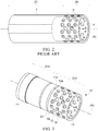
- Fig. 1 shows an exemplary rotor 1 known from the prior art comprising an axis (A) of revolution.
- the rotor 1 comprises a solid shaft 2 extending along the axis (A) and comprising two zones Z1 and Z2 and threads 6.
- Zone Z1 comprises rotor windings 3 wound on the shaft 2 and zone Z2 comprises diode plates 4 fixed by screws 5 screwed into the threads 6.
- the obtaining of the rotor 1 comprises winding operations of the windings 3 on the shaft 2, impregnation of the windings with an insulator, polymerization of the insulator and fixation of the diode plates 4 by means of the screws 5.
- a rotor shaft can, for example, weigh several hundred kilograms, the operations described can be complex to implement.
- this weight influences the dynamics of the rotor by increasing its inertia.
- One method of reducing the weight of the rotor shaft is to ream a portion of the interior of the shaft.
- Fig. 2 shows a partially hollow rotor shaft 7 comprising two zones Z3 and Z4.
- Zone Z3 is intended to accommodate rotor windings and zone Z4 comprises threads 9 intended to accommodate screws for fixing the diode plates.
- Material 8 has been removed from the shaft in zone Z4.
- a first part comprises a first hollow cylindrical element and a second part comprises a second hollow cylindrical element, whereby sections of a first end of the first and second elements are in contact and secured by securing means.
- the securing means comprise bosses regularly distributed over an internal periphery of the first end of the second hollow cylindrical element forming a second ring of bosses, each boss comprising a thread, said means comprising a fixation part and threaded elements each passing through a different thread and cooperating with the fixation part such that each threaded element is parallel to an axis of revolution of the shaft and hold the two sections and the bosses of the first and second hollow cylindrical elements in contact.
- the shaft further comprises guiding means configured such that the hollow cylindrical elements fit together.
- the guiding means comprise a smooth open crown comprising a section merged with the first section of the first hollow cylindrical element followed by a first shoulder and a ring of bosses comprising a free section followed by a second shoulder merged with the first section of the second hollow cylindrical element, an internal diameter of the smooth ring, an external diameter of the ring of bosses and the first and second shoulders being configured such that the internal surface of the smooth ring is in contact with the internal surface of the ring of bosses and the surface of a first shoulder and the surface of a second shoulder are in contact with each other.
- the first hollow cylindrical element comprises a hollow tube intended to accommodate rotor windings on its external perimeter.
- the second hollow cylindrical element comprises a hollow tube comprising perforated holes, through holes and a fixation part configured to accommodate fixation means configured to hold the diode plates on the second hollow cylindrical element.
- a rotor is proposed for a rotating electrical machine comprising a hollow rotor shaft according to one of the preceding claims.
- a method for obtaining a hollow rotor shaft for a rotating electrical machine comprising two parts, each part comprising a hollow cylindrical element.
- the internal surface of a smooth ring incorporated into the first end of a first cylindrical hollow element is brought into contact with the internal surface of a ring of bosses incorporated into the first end of a second cylindrical hollow element and the surface of a first shoulder is brought into contact with the surface of a second shoulder.
- a first hollow cylindrical element is incorporated that comprises a smooth ring configured to accommodate a closing piece and smooth guiding holes configured to guide threaded elements with a second hollow cylindrical element comprising a ring of bosses comprising threads configured to cooperate with the threaded elements by inserting the threaded elements each passing through a different thread and a smooth guide hole such that each threaded element is parallel to an axis of revolution of the shaft and hold the first two sections of the first and second hollow cylindrical elements in contact with each other.
- the shaft 10 comprises a first part Z11 comprising a first hollow cylindrical element 11 and a second part Z12 comprising a second hollow cylindrical element 12.
- a first section S1 of a first end of the cylindrical element 11 is in contact with a first section S2 of a first end facing the second cylindrical element 12.
- the shaft 10 further comprises threaded elements 13 and a closing piece 14.
- the closing piece 14 is embedded in a second end 11b of the first cylindrical element 11 and comprises smooth holes 15 and a central recess 16 allowing the passage of wiring.
- a first end of the threaded elements 13 is fixed in the first end 12a of the second cylindrical element 12, and a second end of the threaded elements 13 is fixed in the closing piece 14, such that the first section S1 of the first end 11a of the first cylindrical element 11 and the first section S2 of the first end 12a of the second cylindrical element 12 are held in contact with each other.
- the first element 11 comprises a hollow tube configured to accommodate, on its external perimeter, rotor windings (not shown).
- the second element 12 comprises a hollow tube comprising perforated through holes 17 and through holes 18 each comprising a counterbore.
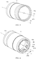
- Figures 5 and 6 show an embodiment of the first hollow cylindrical element 11.
- the first cylindrical element 11 comprises an axis of revolution (A1), the first end 11a, and the second end 11b.
- the first end 11a comprises a first smooth ring 19 comprising a section merged with the first section S1 followed by a first shoulder 20 adapted to accommodate the first end 12a of the second cylindrical element 12.
- the second end 11b comprises a second smooth ring 21 comprising a free section followed by a first ring of bosses 22.
- the bosses 23 incorporated into the first ring of bosses 22 are distributed regularly over an internal periphery of the second end 11b of the element 11 and each comprise a smooth guide hole 24 configured to guide the threaded elements 13.
- the first ring of bosses 22 comprises a section 22a intended to be in contact with the closing piece 14.
- the bosses 23 are configured such that the section 23a of the first ring of bosses 22 is sufficiently large to hold the closing piece 14 in abutment, and such that the bosses 23 are sufficiently rigid to hold the first sections S1 and S2 in contact with each other when the closing piece 14 is embedded in the second smooth ring 21 and the threaded elements 13 are fixed in the first end 12a of the second cylindrical element 12 and cooperate with the closing piece 14 such that the threaded elements are immobilized in the piece 14.
- Each hole 24 is directed along a second axis parallel to the axis of revolution (A1) of the first element 11, for example along a second axis (A2) parallel to the axis (A1).
- the cylindrical element 12 comprises an axis of revolution (B1), the first end 12a, the perforated through holes 17 and the through holes 18 each comprising a counterbore.
- the end 12a comprises a second ring of bosses 25 comprising a free section followed by a second shoulder 26 merged with the first section S2 of the element 12.
- the second ring of bosses 25 comprises bosses 27 each comprising a thread 28 cooperating with the threaded elements 13.
- Each thread 28 is directed along a thread axis parallel to the axis (B1).
- the bosses 27 are distributed regularly over an internal periphery of the first end of the element 12 such as to form the second ring of bosses 25.
- the first and second ring of bosses 22 and 25 of the cylindrical elements 11 and 12 comprise the same number of bosses arranged such that, when the first sections S1 and S2 of the elements 11 and 12 are in contact, the axes of the holes 24 and threads 28 are merged.
- the first and second elements 11 and 12 are secured by securing means comprising the threaded elements 13, the closing piece 14 and the threads 28 in the second ring of bosses 25.
- the threaded element 13 comprises, for example, a screw or a threaded rod and a nut as shown here.
- the threaded element 13 is configured such that its first end is screwed into the thread 28 and its second end cooperates with the closing piece 14, such that, when the sections of the elements 11 and 12 are in contact with each other, the threaded element 13 is parallel to an axis (R) of revolution of the shaft and holds the two sections S1 and S2 of the first ends 11a and 12a in contact with each other.
- the first smooth ring 19, the first and second shoulders 20 and 26 and the second ring of bosses 25 are incorporated into guide means.
- An internal diameter of the first smooth ring 19, an external diameter of the second ring of bosses 25 and the first and second shoulders 20 and 26 are configured such that the internal surface of the first smooth ring 19 is in contact with the internal surface of the second ring of bosses 25 and the surface of a first shoulder 20 and the surface of a second shoulder 26 are in contact with each other.
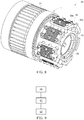
- Figure 8 shows schematically an embodiment of a rotor 29 comprising the elements 11 and 12, diode plates 30, rotor windings 31 and a fixation part 32 for the diode plates 30.
- the fixation part 32 is inserted into the second cylindrical element 12 and comprises threads.
- Each diode plate 30 is fixed on the element 12 by fixation means configured to hold the diode plate on the element 12.
- the fixation means may, for example, comprise hollow spacers 30a and screws 30b.
- a diode plate 30 is connected via the spacers to the element 12 and held by the screws 30b passing through the spacers and the holes 18 each comprising a counterbore and pressing the plate 30 on the spacers 20a.
- the screws 30b are screwed into the threads of the fixation part 32 configured to accommodate the screws 30b.
- the through holes 17 are arranged such that the diode plates 30 can be fixed on the element 12 and the mechanical rigidity of the shaft 10 is not compromised when a rotor comprising the shaft is in motion.
- the perforated holes 17 reduce the weight of the shaft 10. Therefore, the dynamic response of a rotor incorporating the shaft 10 to a stator magnetic field is improved: the response time of the rotor to a magnetic request is reduced.
- the weight reduction is on the order of 75 kg.
- the external diameter of the elements 11 and 12 may be the same as shown here, or may be different.
- a rectifier comprises the hollow cylindrical element 12, the support part 21 and the diode plates 20.
- the rectifier and an assembly comprising the element 11 and the rotor windings 31 may be pre-assembled independently of one another, i.e. the elements 11 and 12 are made independently, the windings are integrated into the element 11 and the diode bridges are fixed to the element 12 independently, for example on two separate production lines, thus facilitating the logistics and organization of the rotor production system.
- the shaft 10 can advantageously be transported and handled in the disassembled state, i.e. when the rectifier R and the assembly comprising the element 11 and the rotor windings are uncoupled.
- the shaft 10 since the electrical and mechanical characteristics of a rotating electrical machine incorporating the shaft 10, in particular the torque generated at the output of the shaft 2, depend on the surface of the windings distributed over the element 11, for a range of rotating electrical machines of the same shaft diameter 2, it is sufficient to modify the assembly comprising the element 11 and the rotor windings to modify the electrical and mechanical characteristics of the range of machines.
- the rectifier R is identical for each of the machines comprising the range.
- the shaft 10 is modular and requires only the adaptation of the assembly comprising the element 11 and the rotor windings to modify the electrical and mechanical characteristics.
- Figure 7 shows an example of a method for obtaining the shaft 10.
- a step 40 the first section S1 of the first element 11 and the first section S2 of the second element 12 are brought into contact.
- the internal surface of the first smooth ring 19 is brought into contact with the internal surface of the second ring of bosses 25, and the surface of the first shoulder 20 is brought into contact with the surface of the second shoulder 26.
- a step 42 the closing piece 14 is inserted into the second end 11b of the element 11 and the threaded elements 13 are inserted and locked in the holes 15 of the piece 14, pass through the smooth guide holes 24 and are screwed into the threads 28.
- Each threaded element 13 passes through a hole 15 of the closing piece 14, a guide hole 24 and a different thread 28, such that each threaded element is parallel to an axis (R) of revolution of the shaft 10 and hold the first two sections (S1, S2) of the first and second hollow cylindrical elements (11, 12) in contact with each other.
- a rotor shaft for a rotating electrical machine may comprise cylindrical elements secured by the securing means and guide means as described above.
Landscapes
- Engineering & Computer Science (AREA)
- General Engineering & Computer Science (AREA)
- Power Engineering (AREA)
- Ocean & Marine Engineering (AREA)
- Mechanical Engineering (AREA)
- Iron Core Of Rotating Electric Machines (AREA)
- Manufacture Of Motors, Generators (AREA)
Applications Claiming Priority (1)
| Application Number | Priority Date | Filing Date | Title |
|---|---|---|---|
| FR1852140A FR3079086B1 (fr) | 2018-03-13 | 2018-03-13 | Arbre rotorique creux pour machine electrique tournante, rotor et procede associes |
Publications (2)
| Publication Number | Publication Date |
|---|---|
| EP3540249A1 true EP3540249A1 (fr) | 2019-09-18 |
| EP3540249B1 EP3540249B1 (fr) | 2021-05-05 |
Family
ID=62528628
Family Applications (1)
| Application Number | Title | Priority Date | Filing Date |
|---|---|---|---|
| EP19162673.8A Active EP3540249B1 (fr) | 2018-03-13 | 2019-03-13 | Arbre creux de rotor de machine électrique rotative, rotor et procédé associés |
Country Status (3)
| Country | Link |
|---|---|
| US (1) | US11095188B2 (fr) |
| EP (1) | EP3540249B1 (fr) |
| FR (1) | FR3079086B1 (fr) |
Citations (4)
| Publication number | Priority date | Publication date | Assignee | Title |
|---|---|---|---|---|
| US3359438A (en) * | 1965-10-01 | 1967-12-19 | Westinghouse Electric Corp | Cooling and shaft coupling arrangement |
| US20030228188A1 (en) * | 2002-06-06 | 2003-12-11 | General Electric Canada Inc. | Dual shaft and rotating machine coupling |
| US20090233721A1 (en) * | 2007-12-28 | 2009-09-17 | Hansen Transmissions International, Naamloze Vennootschap | Method for connecting a low speed main shaft of a wind turbine to an input shaft of a transmission gearbox of the wind turbine and a connection obtained by said method |
| US20110135511A1 (en) * | 2009-12-08 | 2011-06-09 | Olivier Philippart | Motor stand of a primary motor-driven pump unit of a pressurized water nuclear reactor |
Family Cites Families (8)
| Publication number | Priority date | Publication date | Assignee | Title |
|---|---|---|---|---|
| US3501659A (en) * | 1968-02-08 | 1970-03-17 | Rotax Ltd | Rectifying arrangement for dynamo electric machines |
| US4155019A (en) * | 1973-06-27 | 1979-05-15 | Kraftwerk Union Aktiengesellschaft | Coupling assembly for mutually coupling a generator rotor having a superconductive exciter winding and a shaft carrying exciter current leads |
| US4203044A (en) * | 1978-01-16 | 1980-05-13 | Sundstrand Corporation | Double-walled rotor for an oil-cooled electrical machine |
| FR2490422A1 (fr) * | 1980-09-15 | 1982-03-19 | Alsthom Atlantique | Dispositif de connexion entre bague collectrice et amenee de courant d'un rotor supraconducteur |
| DE19943038A1 (de) * | 1999-09-09 | 2001-03-15 | Mannesmann Sachs Ag | Antriebssystem |
| ITMI20112323A1 (it) * | 2011-12-20 | 2013-06-21 | Wilic Sarl | Impianto eolico per la generazione di energia elettrica |
| CN203488533U (zh) * | 2013-08-29 | 2014-03-19 | 中国农业大学 | 一种制粒机用空轴 |
| DE102016216027A1 (de) * | 2016-08-25 | 2018-03-01 | Continental Automotive Gmbh | Kurzschlussläufer für eine Asynchronmaschine |
-
2018
- 2018-03-13 FR FR1852140A patent/FR3079086B1/fr active Active
-
2019
- 2019-03-13 EP EP19162673.8A patent/EP3540249B1/fr active Active
- 2019-03-13 US US16/351,761 patent/US11095188B2/en active Active
Patent Citations (4)
| Publication number | Priority date | Publication date | Assignee | Title |
|---|---|---|---|---|
| US3359438A (en) * | 1965-10-01 | 1967-12-19 | Westinghouse Electric Corp | Cooling and shaft coupling arrangement |
| US20030228188A1 (en) * | 2002-06-06 | 2003-12-11 | General Electric Canada Inc. | Dual shaft and rotating machine coupling |
| US20090233721A1 (en) * | 2007-12-28 | 2009-09-17 | Hansen Transmissions International, Naamloze Vennootschap | Method for connecting a low speed main shaft of a wind turbine to an input shaft of a transmission gearbox of the wind turbine and a connection obtained by said method |
| US20110135511A1 (en) * | 2009-12-08 | 2011-06-09 | Olivier Philippart | Motor stand of a primary motor-driven pump unit of a pressurized water nuclear reactor |
Also Published As
| Publication number | Publication date |
|---|---|
| US11095188B2 (en) | 2021-08-17 |
| FR3079086A1 (fr) | 2019-09-20 |
| US20190288578A1 (en) | 2019-09-19 |
| FR3079086B1 (fr) | 2020-04-17 |
| EP3540249B1 (fr) | 2021-05-05 |
Similar Documents
| Publication | Publication Date | Title |
|---|---|---|
| US4810919A (en) | Low-torque nuts for stator core through-bolts | |
| US6737778B2 (en) | Pulley driving system | |
| US20130106251A1 (en) | Instrument for adjoining temperature detecting element | |
| US9496765B2 (en) | Motor and vibration reduction system for a motor | |
| US11283322B2 (en) | Cage for wound rotor of a synchronous electric machine | |
| EP3166212B1 (fr) | Moteur | |
| US8857225B2 (en) | Washing machine with a direct drive motor system | |
| JP6834479B2 (ja) | モータ | |
| US20190319500A1 (en) | Split core unit, rotary electric machine, method for manufacturing split core unit, and method for manufacturing rotary electric machine | |
| US10355551B2 (en) | Support element and stator assembly comprising the same | |
| US9973060B2 (en) | Motor, pump, and method for manufacturing motor | |
| US2199141A (en) | Dynamoelectric machine | |
| EP3540249A1 (fr) | Arbre creux de rotor de machine électrique rotative, rotor et procédé associés | |
| JP5734645B2 (ja) | モータ用ブラケット、および電動モータ | |
| US9923427B2 (en) | Stator with phase insulation for an electric machine and production method for such a stator | |
| US20020180305A1 (en) | Electrical machine | |
| KR20190043621A (ko) | 스테이터 적층 철심을 위한 세그먼트 시트, 스테이터 적층 철심, 그리고 이를 구비하는 발전기 및 풍력 발전 설비 | |
| US20210099037A1 (en) | Wound-type rotor for a synchronous electric machine | |
| US11139714B2 (en) | Axial gap rotary electric machine | |
| JP3227894U (ja) | 単一モータ駆動型スピンドルを有する繊維機械 | |
| EP4246773A1 (fr) | Stators pour machines électriques | |
| KR102241564B1 (ko) | 영점 고정 부재를 포함하는 모터 시스템 및 이의 제조 및 보수 방법 | |
| US20220209605A1 (en) | Stator design for electrical machine | |
| EP2811619A1 (fr) | Machine électrique rotative | |
| JP2005278333A (ja) | 永久磁石型モータ |
Legal Events
| Date | Code | Title | Description |
|---|---|---|---|
| PUAI | Public reference made under article 153(3) epc to a published international application that has entered the european phase |
Free format text: ORIGINAL CODE: 0009012 |
|
| STAA | Information on the status of an ep patent application or granted ep patent |
Free format text: STATUS: THE APPLICATION HAS BEEN PUBLISHED |
|
| AK | Designated contracting states |
Kind code of ref document: A1 Designated state(s): AL AT BE BG CH CY CZ DE DK EE ES FI FR GB GR HR HU IE IS IT LI LT LU LV MC MK MT NL NO PL PT RO RS SE SI SK SM TR |
|
| AX | Request for extension of the european patent |
Extension state: BA ME |
|
| STAA | Information on the status of an ep patent application or granted ep patent |
Free format text: STATUS: REQUEST FOR EXAMINATION WAS MADE |
|
| 17P | Request for examination filed |
Effective date: 20200317 |
|
| RBV | Designated contracting states (corrected) |
Designated state(s): AL AT BE BG CH CY CZ DE DK EE ES FI FR GB GR HR HU IE IS IT LI LT LU LV MC MK MT NL NO PL PT RO RS SE SI SK SM TR |
|
| STAA | Information on the status of an ep patent application or granted ep patent |
Free format text: STATUS: EXAMINATION IS IN PROGRESS |
|
| 17Q | First examination report despatched |
Effective date: 20200623 |
|
| GRAP | Despatch of communication of intention to grant a patent |
Free format text: ORIGINAL CODE: EPIDOSNIGR1 |
|
| STAA | Information on the status of an ep patent application or granted ep patent |
Free format text: STATUS: GRANT OF PATENT IS INTENDED |
|
| RIC1 | Information provided on ipc code assigned before grant |
Ipc: F16C 3/02 20060101AFI20201110BHEP Ipc: H02K 7/00 20060101ALI20201110BHEP Ipc: H02K 19/38 20060101ALN20201110BHEP |
|
| INTG | Intention to grant announced |
Effective date: 20201126 |
|
| GRAS | Grant fee paid |
Free format text: ORIGINAL CODE: EPIDOSNIGR3 |
|
| GRAA | (expected) grant |
Free format text: ORIGINAL CODE: 0009210 |
|
| STAA | Information on the status of an ep patent application or granted ep patent |
Free format text: STATUS: THE PATENT HAS BEEN GRANTED |
|
| AK | Designated contracting states |
Kind code of ref document: B1 Designated state(s): AL AT BE BG CH CY CZ DE DK EE ES FI FR GB GR HR HU IE IS IT LI LT LU LV MC MK MT NL NO PL PT RO RS SE SI SK SM TR |
|
| REG | Reference to a national code |
Ref country code: GB Ref legal event code: FG4D |
|
| REG | Reference to a national code |
Ref country code: CH Ref legal event code: EP |
|
| REG | Reference to a national code |
Ref country code: AT Ref legal event code: REF Ref document number: 1390167 Country of ref document: AT Kind code of ref document: T Effective date: 20210515 |
|
| REG | Reference to a national code |
Ref country code: DE Ref legal event code: R096 Ref document number: 602019004355 Country of ref document: DE |
|
| REG | Reference to a national code |
Ref country code: IE Ref legal event code: FG4D |
|
| REG | Reference to a national code |
Ref country code: LT Ref legal event code: MG9D |
|
| REG | Reference to a national code |
Ref country code: AT Ref legal event code: MK05 Ref document number: 1390167 Country of ref document: AT Kind code of ref document: T Effective date: 20210505 |
|
| PG25 | Lapsed in a contracting state [announced via postgrant information from national office to epo] |
Ref country code: LT Free format text: LAPSE BECAUSE OF FAILURE TO SUBMIT A TRANSLATION OF THE DESCRIPTION OR TO PAY THE FEE WITHIN THE PRESCRIBED TIME-LIMIT Effective date: 20210505 Ref country code: HR Free format text: LAPSE BECAUSE OF FAILURE TO SUBMIT A TRANSLATION OF THE DESCRIPTION OR TO PAY THE FEE WITHIN THE PRESCRIBED TIME-LIMIT Effective date: 20210505 Ref country code: FI Free format text: LAPSE BECAUSE OF FAILURE TO SUBMIT A TRANSLATION OF THE DESCRIPTION OR TO PAY THE FEE WITHIN THE PRESCRIBED TIME-LIMIT Effective date: 20210505 Ref country code: AT Free format text: LAPSE BECAUSE OF FAILURE TO SUBMIT A TRANSLATION OF THE DESCRIPTION OR TO PAY THE FEE WITHIN THE PRESCRIBED TIME-LIMIT Effective date: 20210505 Ref country code: BG Free format text: LAPSE BECAUSE OF FAILURE TO SUBMIT A TRANSLATION OF THE DESCRIPTION OR TO PAY THE FEE WITHIN THE PRESCRIBED TIME-LIMIT Effective date: 20210805 |
|
| PG25 | Lapsed in a contracting state [announced via postgrant information from national office to epo] |
Ref country code: PT Free format text: LAPSE BECAUSE OF FAILURE TO SUBMIT A TRANSLATION OF THE DESCRIPTION OR TO PAY THE FEE WITHIN THE PRESCRIBED TIME-LIMIT Effective date: 20210906 Ref country code: RS Free format text: LAPSE BECAUSE OF FAILURE TO SUBMIT A TRANSLATION OF THE DESCRIPTION OR TO PAY THE FEE WITHIN THE PRESCRIBED TIME-LIMIT Effective date: 20210505 Ref country code: SE Free format text: LAPSE BECAUSE OF FAILURE TO SUBMIT A TRANSLATION OF THE DESCRIPTION OR TO PAY THE FEE WITHIN THE PRESCRIBED TIME-LIMIT Effective date: 20210505 Ref country code: PL Free format text: LAPSE BECAUSE OF FAILURE TO SUBMIT A TRANSLATION OF THE DESCRIPTION OR TO PAY THE FEE WITHIN THE PRESCRIBED TIME-LIMIT Effective date: 20210505 Ref country code: NO Free format text: LAPSE BECAUSE OF FAILURE TO SUBMIT A TRANSLATION OF THE DESCRIPTION OR TO PAY THE FEE WITHIN THE PRESCRIBED TIME-LIMIT Effective date: 20210805 Ref country code: LV Free format text: LAPSE BECAUSE OF FAILURE TO SUBMIT A TRANSLATION OF THE DESCRIPTION OR TO PAY THE FEE WITHIN THE PRESCRIBED TIME-LIMIT Effective date: 20210505 Ref country code: GR Free format text: LAPSE BECAUSE OF FAILURE TO SUBMIT A TRANSLATION OF THE DESCRIPTION OR TO PAY THE FEE WITHIN THE PRESCRIBED TIME-LIMIT Effective date: 20210806 Ref country code: IS Free format text: LAPSE BECAUSE OF FAILURE TO SUBMIT A TRANSLATION OF THE DESCRIPTION OR TO PAY THE FEE WITHIN THE PRESCRIBED TIME-LIMIT Effective date: 20210905 |
|
| REG | Reference to a national code |
Ref country code: NL Ref legal event code: MP Effective date: 20210505 |
|
| PG25 | Lapsed in a contracting state [announced via postgrant information from national office to epo] |
Ref country code: NL Free format text: LAPSE BECAUSE OF FAILURE TO SUBMIT A TRANSLATION OF THE DESCRIPTION OR TO PAY THE FEE WITHIN THE PRESCRIBED TIME-LIMIT Effective date: 20210505 |
|
| PG25 | Lapsed in a contracting state [announced via postgrant information from national office to epo] |
Ref country code: CZ Free format text: LAPSE BECAUSE OF FAILURE TO SUBMIT A TRANSLATION OF THE DESCRIPTION OR TO PAY THE FEE WITHIN THE PRESCRIBED TIME-LIMIT Effective date: 20210505 Ref country code: DK Free format text: LAPSE BECAUSE OF FAILURE TO SUBMIT A TRANSLATION OF THE DESCRIPTION OR TO PAY THE FEE WITHIN THE PRESCRIBED TIME-LIMIT Effective date: 20210505 Ref country code: RO Free format text: LAPSE BECAUSE OF FAILURE TO SUBMIT A TRANSLATION OF THE DESCRIPTION OR TO PAY THE FEE WITHIN THE PRESCRIBED TIME-LIMIT Effective date: 20210505 Ref country code: SM Free format text: LAPSE BECAUSE OF FAILURE TO SUBMIT A TRANSLATION OF THE DESCRIPTION OR TO PAY THE FEE WITHIN THE PRESCRIBED TIME-LIMIT Effective date: 20210505 Ref country code: SK Free format text: LAPSE BECAUSE OF FAILURE TO SUBMIT A TRANSLATION OF THE DESCRIPTION OR TO PAY THE FEE WITHIN THE PRESCRIBED TIME-LIMIT Effective date: 20210505 Ref country code: EE Free format text: LAPSE BECAUSE OF FAILURE TO SUBMIT A TRANSLATION OF THE DESCRIPTION OR TO PAY THE FEE WITHIN THE PRESCRIBED TIME-LIMIT Effective date: 20210505 Ref country code: ES Free format text: LAPSE BECAUSE OF FAILURE TO SUBMIT A TRANSLATION OF THE DESCRIPTION OR TO PAY THE FEE WITHIN THE PRESCRIBED TIME-LIMIT Effective date: 20210505 |
|
| REG | Reference to a national code |
Ref country code: DE Ref legal event code: R097 Ref document number: 602019004355 Country of ref document: DE |
|
| PLBE | No opposition filed within time limit |
Free format text: ORIGINAL CODE: 0009261 |
|
| STAA | Information on the status of an ep patent application or granted ep patent |
Free format text: STATUS: NO OPPOSITION FILED WITHIN TIME LIMIT |
|
| 26N | No opposition filed |
Effective date: 20220208 |
|
| PG25 | Lapsed in a contracting state [announced via postgrant information from national office to epo] |
Ref country code: IS Free format text: LAPSE BECAUSE OF FAILURE TO SUBMIT A TRANSLATION OF THE DESCRIPTION OR TO PAY THE FEE WITHIN THE PRESCRIBED TIME-LIMIT Effective date: 20210905 Ref country code: AL Free format text: LAPSE BECAUSE OF FAILURE TO SUBMIT A TRANSLATION OF THE DESCRIPTION OR TO PAY THE FEE WITHIN THE PRESCRIBED TIME-LIMIT Effective date: 20210505 |
|
| PG25 | Lapsed in a contracting state [announced via postgrant information from national office to epo] |
Ref country code: IT Free format text: LAPSE BECAUSE OF FAILURE TO SUBMIT A TRANSLATION OF THE DESCRIPTION OR TO PAY THE FEE WITHIN THE PRESCRIBED TIME-LIMIT Effective date: 20210505 |
|
| PG25 | Lapsed in a contracting state [announced via postgrant information from national office to epo] |
Ref country code: MC Free format text: LAPSE BECAUSE OF FAILURE TO SUBMIT A TRANSLATION OF THE DESCRIPTION OR TO PAY THE FEE WITHIN THE PRESCRIBED TIME-LIMIT Effective date: 20210505 |
|
| REG | Reference to a national code |
Ref country code: CH Ref legal event code: PL |
|
| REG | Reference to a national code |
Ref country code: BE Ref legal event code: MM Effective date: 20220331 |
|
| PG25 | Lapsed in a contracting state [announced via postgrant information from national office to epo] |
Ref country code: LU Free format text: LAPSE BECAUSE OF NON-PAYMENT OF DUE FEES Effective date: 20220313 Ref country code: LI Free format text: LAPSE BECAUSE OF NON-PAYMENT OF DUE FEES Effective date: 20220331 Ref country code: IE Free format text: LAPSE BECAUSE OF NON-PAYMENT OF DUE FEES Effective date: 20220313 Ref country code: CH Free format text: LAPSE BECAUSE OF NON-PAYMENT OF DUE FEES Effective date: 20220331 |
|
| PG25 | Lapsed in a contracting state [announced via postgrant information from national office to epo] |
Ref country code: BE Free format text: LAPSE BECAUSE OF NON-PAYMENT OF DUE FEES Effective date: 20220331 |
|
| PGFP | Annual fee paid to national office [announced via postgrant information from national office to epo] |
Ref country code: FR Payment date: 20230222 Year of fee payment: 5 |
|
| PG25 | Lapsed in a contracting state [announced via postgrant information from national office to epo] |
Ref country code: MK Free format text: LAPSE BECAUSE OF FAILURE TO SUBMIT A TRANSLATION OF THE DESCRIPTION OR TO PAY THE FEE WITHIN THE PRESCRIBED TIME-LIMIT Effective date: 20210505 Ref country code: CY Free format text: LAPSE BECAUSE OF FAILURE TO SUBMIT A TRANSLATION OF THE DESCRIPTION OR TO PAY THE FEE WITHIN THE PRESCRIBED TIME-LIMIT Effective date: 20210505 |
|
| PGFP | Annual fee paid to national office [announced via postgrant information from national office to epo] |
Ref country code: DE Payment date: 20240220 Year of fee payment: 6 Ref country code: GB Payment date: 20240221 Year of fee payment: 6 |